EP2501437B1 - Flash x-ray irradiator - Google Patents
Flash x-ray irradiator Download PDFInfo
- Publication number
- EP2501437B1 EP2501437B1 EP09747778.0A EP09747778A EP2501437B1 EP 2501437 B1 EP2501437 B1 EP 2501437B1 EP 09747778 A EP09747778 A EP 09747778A EP 2501437 B1 EP2501437 B1 EP 2501437B1
- Authority
- EP
- European Patent Office
- Prior art keywords
- anode
- cathode
- ray
- flash
- grid
- Prior art date
- Legal status (The legal status is an assumption and is not a legal conclusion. Google has not performed a legal analysis and makes no representation as to the accuracy of the status listed.)
- Active
Links
- 239000000463 material Substances 0.000 claims description 51
- 239000003990 capacitor Substances 0.000 claims description 30
- 238000004146 energy storage Methods 0.000 claims description 13
- 238000011065 in-situ storage Methods 0.000 claims description 7
- 150000002894 organic compounds Chemical class 0.000 claims description 4
- 230000005484 gravity Effects 0.000 claims 1
- 230000005855 radiation Effects 0.000 description 30
- 230000001954 sterilising effect Effects 0.000 description 29
- 238000004659 sterilization and disinfection Methods 0.000 description 26
- 238000005202 decontamination Methods 0.000 description 20
- 230000003588 decontaminative effect Effects 0.000 description 17
- 238000005516 engineering process Methods 0.000 description 17
- 238000005067 remediation Methods 0.000 description 16
- 238000000034 method Methods 0.000 description 13
- XLYOFNOQVPJJNP-UHFFFAOYSA-N water Substances O XLYOFNOQVPJJNP-UHFFFAOYSA-N 0.000 description 13
- 150000002430 hydrocarbons Chemical class 0.000 description 12
- 238000004519 manufacturing process Methods 0.000 description 12
- 239000003921 oil Substances 0.000 description 12
- 230000007613 environmental effect Effects 0.000 description 11
- 239000000356 contaminant Substances 0.000 description 10
- 229930195733 hydrocarbon Natural products 0.000 description 10
- 239000002699 waste material Substances 0.000 description 10
- 239000010941 cobalt Substances 0.000 description 9
- 229910017052 cobalt Inorganic materials 0.000 description 9
- GUTLYIVDDKVIGB-UHFFFAOYSA-N cobalt atom Chemical compound [Co] GUTLYIVDDKVIGB-UHFFFAOYSA-N 0.000 description 9
- 238000011109 contamination Methods 0.000 description 9
- 150000001875 compounds Chemical class 0.000 description 8
- 230000008569 process Effects 0.000 description 8
- 238000003860 storage Methods 0.000 description 8
- 239000004215 Carbon black (E152) Substances 0.000 description 7
- 238000013461 design Methods 0.000 description 7
- 239000002828 fuel tank Substances 0.000 description 7
- 150000003071 polychlorinated biphenyls Chemical class 0.000 description 7
- 150000002013 dioxins Chemical class 0.000 description 6
- 241000193738 Bacillus anthracis Species 0.000 description 5
- 241000894006 Bacteria Species 0.000 description 5
- ZAMOUSCENKQFHK-UHFFFAOYSA-N Chlorine atom Chemical compound [Cl] ZAMOUSCENKQFHK-UHFFFAOYSA-N 0.000 description 5
- 239000000460 chlorine Substances 0.000 description 5
- 229910052801 chlorine Inorganic materials 0.000 description 5
- 238000000354 decomposition reaction Methods 0.000 description 5
- 235000013305 food Nutrition 0.000 description 5
- 239000007789 gas Substances 0.000 description 5
- 229940127554 medical product Drugs 0.000 description 5
- 239000000047 product Substances 0.000 description 5
- 239000010865 sewage Substances 0.000 description 5
- 241000894007 species Species 0.000 description 5
- 239000000126 substance Substances 0.000 description 5
- 230000009182 swimming Effects 0.000 description 5
- 239000012855 volatile organic compound Substances 0.000 description 5
- RAHZWNYVWXNFOC-UHFFFAOYSA-N Sulphur dioxide Chemical compound O=S=O RAHZWNYVWXNFOC-UHFFFAOYSA-N 0.000 description 4
- 235000012206 bottled water Nutrition 0.000 description 4
- 239000006227 byproduct Substances 0.000 description 4
- 239000003651 drinking water Substances 0.000 description 4
- 239000000975 dye Substances 0.000 description 4
- 238000012545 processing Methods 0.000 description 4
- 239000002689 soil Substances 0.000 description 4
- KVGZZAHHUNAVKZ-UHFFFAOYSA-N 1,4-Dioxin Chemical group O1C=COC=C1 KVGZZAHHUNAVKZ-UHFFFAOYSA-N 0.000 description 3
- 230000003466 anti-cipated effect Effects 0.000 description 3
- 238000010586 diagram Methods 0.000 description 3
- 239000002906 medical waste Substances 0.000 description 3
- 238000009372 pisciculture Methods 0.000 description 3
- 239000004033 plastic Substances 0.000 description 3
- 229920003023 plastic Polymers 0.000 description 3
- 241000251468 Actinopterygii Species 0.000 description 2
- 230000005461 Bremsstrahlung Effects 0.000 description 2
- 241001465754 Metazoa Species 0.000 description 2
- ZOKXTWBITQBERF-UHFFFAOYSA-N Molybdenum Chemical compound [Mo] ZOKXTWBITQBERF-UHFFFAOYSA-N 0.000 description 2
- 230000008901 benefit Effects 0.000 description 2
- 230000005540 biological transmission Effects 0.000 description 2
- 229910052797 bismuth Inorganic materials 0.000 description 2
- JCXGWMGPZLAOME-UHFFFAOYSA-N bismuth atom Chemical compound [Bi] JCXGWMGPZLAOME-UHFFFAOYSA-N 0.000 description 2
- 238000004364 calculation method Methods 0.000 description 2
- 239000003653 coastal water Substances 0.000 description 2
- 239000000567 combustion gas Substances 0.000 description 2
- 239000003814 drug Substances 0.000 description 2
- 229920001971 elastomer Polymers 0.000 description 2
- 239000000806 elastomer Substances 0.000 description 2
- 238000010894 electron beam technology Methods 0.000 description 2
- 235000019688 fish Nutrition 0.000 description 2
- 230000004907 flux Effects 0.000 description 2
- 239000010795 gaseous waste Substances 0.000 description 2
- 239000003502 gasoline Substances 0.000 description 2
- 239000003673 groundwater Substances 0.000 description 2
- 230000012447 hatching Effects 0.000 description 2
- -1 heterocyclic organic compound Chemical class 0.000 description 2
- 230000001939 inductive effect Effects 0.000 description 2
- 238000009413 insulation Methods 0.000 description 2
- 239000011133 lead Substances 0.000 description 2
- 238000012423 maintenance Methods 0.000 description 2
- 238000013508 migration Methods 0.000 description 2
- 230000005012 migration Effects 0.000 description 2
- 230000000116 mitigating effect Effects 0.000 description 2
- 229910052750 molybdenum Inorganic materials 0.000 description 2
- 239000011733 molybdenum Substances 0.000 description 2
- 235000019645 odor Nutrition 0.000 description 2
- 244000052769 pathogen Species 0.000 description 2
- 238000005086 pumping Methods 0.000 description 2
- 230000001105 regulatory effect Effects 0.000 description 2
- 238000011160 research Methods 0.000 description 2
- 239000010802 sludge Substances 0.000 description 2
- 125000002730 succinyl group Chemical group C(CCC(=O)*)(=O)* 0.000 description 2
- WFKWXMTUELFFGS-UHFFFAOYSA-N tungsten Chemical compound [W] WFKWXMTUELFFGS-UHFFFAOYSA-N 0.000 description 2
- 229910052721 tungsten Inorganic materials 0.000 description 2
- 239000010937 tungsten Substances 0.000 description 2
- 239000003643 water by type Substances 0.000 description 2
- 241000972773 Aulopiformes Species 0.000 description 1
- 206010073306 Exposure to radiation Diseases 0.000 description 1
- 241000238634 Libellulidae Species 0.000 description 1
- GQPLMRYTRLFLPF-UHFFFAOYSA-N Nitrous Oxide Chemical class [O-][N+]#N GQPLMRYTRLFLPF-UHFFFAOYSA-N 0.000 description 1
- 229910019142 PO4 Inorganic materials 0.000 description 1
- 241000282887 Suidae Species 0.000 description 1
- 230000002378 acidificating effect Effects 0.000 description 1
- 238000003915 air pollution Methods 0.000 description 1
- 238000013459 approach Methods 0.000 description 1
- 230000003190 augmentative effect Effects 0.000 description 1
- 229940065181 bacillus anthracis Drugs 0.000 description 1
- 238000003287 bathing Methods 0.000 description 1
- 231100000693 bioaccumulation Toxicity 0.000 description 1
- 239000008280 blood Substances 0.000 description 1
- 210000004369 blood Anatomy 0.000 description 1
- 210000001124 body fluid Anatomy 0.000 description 1
- 231100000357 carcinogen Toxicity 0.000 description 1
- 239000003183 carcinogenic agent Substances 0.000 description 1
- 239000003638 chemical reducing agent Substances 0.000 description 1
- 238000004040 coloring Methods 0.000 description 1
- 238000010276 construction Methods 0.000 description 1
- 230000006378 damage Effects 0.000 description 1
- 230000002498 deadly effect Effects 0.000 description 1
- 150000004827 dibenzo-1,4-dioxins Chemical class 0.000 description 1
- 230000009977 dual effect Effects 0.000 description 1
- 230000000694 effects Effects 0.000 description 1
- 230000005684 electric field Effects 0.000 description 1
- 230000008030 elimination Effects 0.000 description 1
- 238000003379 elimination reaction Methods 0.000 description 1
- 239000004744 fabric Substances 0.000 description 1
- 239000003925 fat Substances 0.000 description 1
- 210000003608 fece Anatomy 0.000 description 1
- 238000007667 floating Methods 0.000 description 1
- 238000009930 food irradiation Methods 0.000 description 1
- 239000013505 freshwater Substances 0.000 description 1
- 239000000446 fuel Substances 0.000 description 1
- 150000008282 halocarbons Chemical class 0.000 description 1
- 231100001261 hazardous Toxicity 0.000 description 1
- 230000036541 health Effects 0.000 description 1
- 208000015181 infectious disease Diseases 0.000 description 1
- 230000002458 infectious effect Effects 0.000 description 1
- 239000000976 ink Substances 0.000 description 1
- 238000009434 installation Methods 0.000 description 1
- 230000003993 interaction Effects 0.000 description 1
- 230000001678 irradiating effect Effects 0.000 description 1
- 230000007794 irritation Effects 0.000 description 1
- 150000002632 lipids Chemical class 0.000 description 1
- 230000014759 maintenance of location Effects 0.000 description 1
- 238000005259 measurement Methods 0.000 description 1
- 239000000203 mixture Substances 0.000 description 1
- 238000012986 modification Methods 0.000 description 1
- 230000004048 modification Effects 0.000 description 1
- 238000012544 monitoring process Methods 0.000 description 1
- 239000003471 mutagenic agent Substances 0.000 description 1
- 231100000707 mutagenic chemical Toxicity 0.000 description 1
- 239000012454 non-polar solvent Substances 0.000 description 1
- 230000001473 noxious effect Effects 0.000 description 1
- 239000003305 oil spill Substances 0.000 description 1
- 150000002896 organic halogen compounds Chemical class 0.000 description 1
- 235000021485 packed food Nutrition 0.000 description 1
- 230000035515 penetration Effects 0.000 description 1
- 239000000825 pharmaceutical preparation Substances 0.000 description 1
- 229940127557 pharmaceutical product Drugs 0.000 description 1
- NBIIXXVUZAFLBC-UHFFFAOYSA-K phosphate Chemical compound [O-]P([O-])([O-])=O NBIIXXVUZAFLBC-UHFFFAOYSA-K 0.000 description 1
- 239000010452 phosphate Substances 0.000 description 1
- 238000006116 polymerization reaction Methods 0.000 description 1
- 238000007639 printing Methods 0.000 description 1
- 239000010909 process residue Substances 0.000 description 1
- 230000009467 reduction Effects 0.000 description 1
- 238000005057 refrigeration Methods 0.000 description 1
- 235000019515 salmon Nutrition 0.000 description 1
- 239000013535 sea water Substances 0.000 description 1
- 230000000153 supplemental effect Effects 0.000 description 1
- 231100000462 teratogen Toxicity 0.000 description 1
- 239000003439 teratogenic agent Substances 0.000 description 1
- 231100000331 toxic Toxicity 0.000 description 1
- 231100000167 toxic agent Toxicity 0.000 description 1
- 230000002588 toxic effect Effects 0.000 description 1
- 231100000765 toxin Toxicity 0.000 description 1
- 230000001960 triggered effect Effects 0.000 description 1
- 210000002700 urine Anatomy 0.000 description 1
- 239000003981 vehicle Substances 0.000 description 1
Images


Classifications
-
- H—ELECTRICITY
- H01—ELECTRIC ELEMENTS
- H01J—ELECTRIC DISCHARGE TUBES OR DISCHARGE LAMPS
- H01J35/00—X-ray tubes
- H01J35/02—Details
- H01J35/04—Electrodes ; Mutual position thereof; Constructional adaptations therefor
- H01J35/06—Cathodes
- H01J35/065—Field emission, photo emission or secondary emission cathodes
-
- A—HUMAN NECESSITIES
- A23—FOODS OR FOODSTUFFS; TREATMENT THEREOF, NOT COVERED BY OTHER CLASSES
- A23L—FOODS, FOODSTUFFS, OR NON-ALCOHOLIC BEVERAGES, NOT COVERED BY SUBCLASSES A21D OR A23B-A23J; THEIR PREPARATION OR TREATMENT, e.g. COOKING, MODIFICATION OF NUTRITIVE QUALITIES, PHYSICAL TREATMENT; PRESERVATION OF FOODS OR FOODSTUFFS, IN GENERAL
- A23L3/00—Preservation of foods or foodstuffs, in general, e.g. pasteurising, sterilising, specially adapted for foods or foodstuffs
- A23L3/26—Preservation of foods or foodstuffs, in general, e.g. pasteurising, sterilising, specially adapted for foods or foodstuffs by irradiation without heating
- A23L3/263—Preservation of foods or foodstuffs, in general, e.g. pasteurising, sterilising, specially adapted for foods or foodstuffs by irradiation without heating with corpuscular or ionising radiation, i.e. X, alpha, beta or omega radiation
-
- A—HUMAN NECESSITIES
- A61—MEDICAL OR VETERINARY SCIENCE; HYGIENE
- A61L—METHODS OR APPARATUS FOR STERILISING MATERIALS OR OBJECTS IN GENERAL; DISINFECTION, STERILISATION OR DEODORISATION OF AIR; CHEMICAL ASPECTS OF BANDAGES, DRESSINGS, ABSORBENT PADS OR SURGICAL ARTICLES; MATERIALS FOR BANDAGES, DRESSINGS, ABSORBENT PADS OR SURGICAL ARTICLES
- A61L11/00—Methods specially adapted for refuse
-
- A—HUMAN NECESSITIES
- A61—MEDICAL OR VETERINARY SCIENCE; HYGIENE
- A61L—METHODS OR APPARATUS FOR STERILISING MATERIALS OR OBJECTS IN GENERAL; DISINFECTION, STERILISATION OR DEODORISATION OF AIR; CHEMICAL ASPECTS OF BANDAGES, DRESSINGS, ABSORBENT PADS OR SURGICAL ARTICLES; MATERIALS FOR BANDAGES, DRESSINGS, ABSORBENT PADS OR SURGICAL ARTICLES
- A61L2/00—Methods or apparatus for disinfecting or sterilising materials or objects other than foodstuffs or contact lenses; Accessories therefor
- A61L2/0005—Methods or apparatus for disinfecting or sterilising materials or objects other than foodstuffs or contact lenses; Accessories therefor for pharmaceuticals, biologicals or living parts
- A61L2/0011—Methods or apparatus for disinfecting or sterilising materials or objects other than foodstuffs or contact lenses; Accessories therefor for pharmaceuticals, biologicals or living parts using physical methods
-
- A—HUMAN NECESSITIES
- A61—MEDICAL OR VETERINARY SCIENCE; HYGIENE
- A61L—METHODS OR APPARATUS FOR STERILISING MATERIALS OR OBJECTS IN GENERAL; DISINFECTION, STERILISATION OR DEODORISATION OF AIR; CHEMICAL ASPECTS OF BANDAGES, DRESSINGS, ABSORBENT PADS OR SURGICAL ARTICLES; MATERIALS FOR BANDAGES, DRESSINGS, ABSORBENT PADS OR SURGICAL ARTICLES
- A61L2/00—Methods or apparatus for disinfecting or sterilising materials or objects other than foodstuffs or contact lenses; Accessories therefor
- A61L2/02—Methods or apparatus for disinfecting or sterilising materials or objects other than foodstuffs or contact lenses; Accessories therefor using physical phenomena
- A61L2/08—Radiation
- A61L2/082—X-rays
-
- B—PERFORMING OPERATIONS; TRANSPORTING
- B09—DISPOSAL OF SOLID WASTE; RECLAMATION OF CONTAMINATED SOIL
- B09C—RECLAMATION OF CONTAMINATED SOIL
- B09C1/00—Reclamation of contaminated soil
- B09C1/002—Reclamation of contaminated soil involving in-situ ground water treatment
-
- B—PERFORMING OPERATIONS; TRANSPORTING
- B09—DISPOSAL OF SOLID WASTE; RECLAMATION OF CONTAMINATED SOIL
- B09C—RECLAMATION OF CONTAMINATED SOIL
- B09C1/00—Reclamation of contaminated soil
- B09C1/08—Reclamation of contaminated soil chemically
-
- C—CHEMISTRY; METALLURGY
- C02—TREATMENT OF WATER, WASTE WATER, SEWAGE, OR SLUDGE
- C02F—TREATMENT OF WATER, WASTE WATER, SEWAGE, OR SLUDGE
- C02F1/00—Treatment of water, waste water, or sewage
- C02F1/008—Control or steering systems not provided for elsewhere in subclass C02F
-
- C—CHEMISTRY; METALLURGY
- C02—TREATMENT OF WATER, WASTE WATER, SEWAGE, OR SLUDGE
- C02F—TREATMENT OF WATER, WASTE WATER, SEWAGE, OR SLUDGE
- C02F1/00—Treatment of water, waste water, or sewage
- C02F1/30—Treatment of water, waste water, or sewage by irradiation
- C02F1/305—Treatment of water, waste water, or sewage by irradiation with electrons
-
- H—ELECTRICITY
- H01—ELECTRIC ELEMENTS
- H01J—ELECTRIC DISCHARGE TUBES OR DISCHARGE LAMPS
- H01J35/00—X-ray tubes
- H01J35/02—Details
- H01J35/04—Electrodes ; Mutual position thereof; Constructional adaptations therefor
- H01J35/045—Electrodes for controlling the current of the cathode ray, e.g. control grids
-
- H—ELECTRICITY
- H01—ELECTRIC ELEMENTS
- H01J—ELECTRIC DISCHARGE TUBES OR DISCHARGE LAMPS
- H01J35/00—X-ray tubes
- H01J35/02—Details
- H01J35/04—Electrodes ; Mutual position thereof; Constructional adaptations therefor
- H01J35/08—Anodes; Anti cathodes
- H01J35/112—Non-rotating anodes
-
- H—ELECTRICITY
- H01—ELECTRIC ELEMENTS
- H01J—ELECTRIC DISCHARGE TUBES OR DISCHARGE LAMPS
- H01J35/00—X-ray tubes
- H01J35/02—Details
- H01J35/16—Vessels; Containers; Shields associated therewith
-
- H—ELECTRICITY
- H01—ELECTRIC ELEMENTS
- H01J—ELECTRIC DISCHARGE TUBES OR DISCHARGE LAMPS
- H01J35/00—X-ray tubes
- H01J35/22—X-ray tubes specially designed for passing a very high current for a very short time, e.g. for flash operation
-
- H—ELECTRICITY
- H05—ELECTRIC TECHNIQUES NOT OTHERWISE PROVIDED FOR
- H05G—X-RAY TECHNIQUE
- H05G1/00—X-ray apparatus involving X-ray tubes; Circuits therefor
- H05G1/08—Electrical details
- H05G1/10—Power supply arrangements for feeding the X-ray tube
- H05G1/22—Power supply arrangements for feeding the X-ray tube with single pulses
- H05G1/24—Obtaining pulses by using energy storage devices
-
- C—CHEMISTRY; METALLURGY
- C02—TREATMENT OF WATER, WASTE WATER, SEWAGE, OR SLUDGE
- C02F—TREATMENT OF WATER, WASTE WATER, SEWAGE, OR SLUDGE
- C02F1/00—Treatment of water, waste water, or sewage
- C02F1/30—Treatment of water, waste water, or sewage by irradiation
- C02F1/307—Treatment of water, waste water, or sewage by irradiation with X-rays or gamma radiation
-
- C—CHEMISTRY; METALLURGY
- C02—TREATMENT OF WATER, WASTE WATER, SEWAGE, OR SLUDGE
- C02F—TREATMENT OF WATER, WASTE WATER, SEWAGE, OR SLUDGE
- C02F2201/00—Apparatus for treatment of water, waste water or sewage
- C02F2201/008—Mobile apparatus and plants, e.g. mounted on a vehicle
-
- C—CHEMISTRY; METALLURGY
- C02—TREATMENT OF WATER, WASTE WATER, SEWAGE, OR SLUDGE
- C02F—TREATMENT OF WATER, WASTE WATER, SEWAGE, OR SLUDGE
- C02F2201/00—Apparatus for treatment of water, waste water or sewage
- C02F2201/32—Details relating to UV-irradiation devices
- C02F2201/326—Lamp control systems
-
- C—CHEMISTRY; METALLURGY
- C02—TREATMENT OF WATER, WASTE WATER, SEWAGE, OR SLUDGE
- C02F—TREATMENT OF WATER, WASTE WATER, SEWAGE, OR SLUDGE
- C02F2303/00—Specific treatment goals
- C02F2303/04—Disinfection
-
- H—ELECTRICITY
- H01—ELECTRIC ELEMENTS
- H01J—ELECTRIC DISCHARGE TUBES OR DISCHARGE LAMPS
- H01J2235/00—X-ray tubes
- H01J2235/06—Cathode assembly
- H01J2235/062—Cold cathodes
-
- H—ELECTRICITY
- H01—ELECTRIC ELEMENTS
- H01J—ELECTRIC DISCHARGE TUBES OR DISCHARGE LAMPS
- H01J2235/00—X-ray tubes
- H01J2235/06—Cathode assembly
- H01J2235/068—Multi-cathode assembly
-
- H—ELECTRICITY
- H01—ELECTRIC ELEMENTS
- H01J—ELECTRIC DISCHARGE TUBES OR DISCHARGE LAMPS
- H01J2235/00—X-ray tubes
- H01J2235/08—Targets (anodes) and X-ray converters
- H01J2235/086—Target geometry
-
- H—ELECTRICITY
- H01—ELECTRIC ELEMENTS
- H01J—ELECTRIC DISCHARGE TUBES OR DISCHARGE LAMPS
- H01J35/00—X-ray tubes
- H01J35/02—Details
- H01J35/04—Electrodes ; Mutual position thereof; Constructional adaptations therefor
- H01J35/08—Anodes; Anti cathodes
- H01J35/112—Non-rotating anodes
- H01J35/116—Transmissive anodes
Definitions
- the present invention relates to apparatus for irradiation of materials.
- the invention relates more particularly to an apparatus that produces a high speed X-ray pulse or pulses for irradiation of materials.
- Sterilization of various materials by irradiation with high-energy radiation is a well-established technology.
- High-energy irradiation can break molecular bonds in various materials and decompose the toxic compounds into more benign compounds.
- Gamma sterilization has been considered the norm up until now because of the high energy and fluence (amount of radiation delivered per unit of time) of the source.
- Use of X-ray irradiation for manufacturing purposes such as the manufacture of heat-shrink tubing for electronics is also known.
- 60 Cobalt For sterilization with gamma radiation, 60 Cobalt has been the standard radioisotope of choice. 60 Cobalt emits gamma rays at energies of 1.17 MeV and 1.33 MeV. The efficacy of radiation at these energies has been long established for these applications.
- One of the drawbacks to the use of 60 Cobalt is that its higher energy line (1.33 MeV) is above the energy level at which radioactivity is induced.
- an irradiation apparatus whose maximum energy output is below the threshold of 60 Cobalt, so as to avoid the problem of inducing radioactivity in material being irradiated. It would further be desirable to provide an apparatus for irradiation that altogether avoids the use of radioisotopes, so as simplify operation and licensing, and eliminate the possibility of diversion of such radioisotopes for illegal purposes.
- Prior X-ray sources have not achieved a position of dominance due to the fact that although they can easily achieve higher energies, they have heretofore been unable to economically achieve the fluence of gamma sources.
- the invention provides an apparatus for Flash X-ray irradiation of material, referred to in this description as a Flash X-ray Irradiator r (FXI) as defined in claim 1.
- FXI Flash X-ray Irradiator r
- the Flash X-ray Irradiator has a maximum energy output below the threshold of 60 Cobalt, so as to avoid the problem of inducing radioactivity in material being irradiated.
- the Flash X-ray Irradiator also avoids the use of radioisotopes, as in the prior art use of 60 Cobalt for irradiation, so as simplify operation and licensing, and eliminate the possibility of diversion of such radioisotopes for illegal purposes.
- the Flash X-ray Irradiator can simultaneously achieve both the high energy and fluence necessary for practical sterilization, decontamination, and environmental remediation applications. It can also be used for various manufacturing processes.
- FIGS. 1 and 2 show two different embodiments of a Flash X-Ray Irradiator (FXI).
- An FXI is generally a transmission type X-ray tube. It is differentiated from the prior art by several features. The first is its electron gun, which, in FIG. 1 , comprises a cathode 111 and a grid 113, and in FIG. 2 comprises a cathode 112 and a grid 114. These electron guns can achieve current densities up to 80,000 Amps/cm 2 in the pulse mode, which ultimately result in high levels of irradiation.
- the FXI can achieve high energy of typically 0.1 - 5 MeV, a high beam current of typically 50 KiloAmp - 1 MegaAmp pulses, a high fluence of typically 16 KiloGrey/pulse, and a repetition rate typically up to 100 Hz.
- the Flash X-ray Irradiator 109 of FIG. 1 may advantageously include a supplementary energy storage capacitor 124a which would be coaxially wound around the cathode 111. This allows local storage of substantially greater amounts of energy without changing the physical size of the Flash X-ray Irradiator 109.
- a planar implementation of a supplementary energy storage capacitor may be advantageously incorporated in the planar Flash X-ray Irradiator 110.
- FIG. 2A which is modified to include a supplementary storage capacitor 124b between cathode support 144 and the cathode 112, for the same purpose as the supplementary storage capacitor 124a of FIG. 1 .
- the cathode 111 or 112 is charged by the power supply 130a or 130b or 130c of FIGS. 3 or 4A or 4B , respectively.
- a bias resistor (not shown) is connected between the cathode 111 or 112 and the grid 113 or 114 and is used to create a voltage on the grid so that the tube is normally in a standoff condition (not conducting).
- a control signal of ground potential is applied to the grid, it releases control of the cathode and the cathode discharges. Electrons then travel from the cathode to the anode 115 or 116. When they strike the anode, the create Bremsstrahlung X-radiation.
- Bremsstrahlung is German for "braking radiation” and is created when electrons 134 with a potential in excess of 23 kiloVolts are suddenly stopped, in this case by striking the anode. When they hit the anode, a mixture of X-radiation 136 and secondary electrons (not shown) are liberated from an X-ray emitting surface of the anode in an isotropic fashion. Since the anode is thin in comparison to the penetration depth of the incident electrons, there is a preponderance of X-radiation transmitted from an electron-receiving surface of the anode, through the anode, to an irradiation volume beyond.
- the thickness of the anode of the X-ray tube 109 or 110 is chosen to enable generation of a desired level of X-radiation.
- the thickness of the anode depends on a combination of factors, including the desired output voltage, the incident electron voltage, and the atomic number of the material from which it is fabricated, which number is typically over 50.
- the cathode and grid are fabricated to extremely tight tolerances, typically on the order of 25 microns on any dimension, even if the structure is meters long.
- the X-ray tube 109 or 110 is pumped to an extremely high vacuum, typically on the order of 1 x 10 -9 Torr ( i.e. 1.33 x 10 -7 Pa).
- X-ray tube 109 or 110 incorporate radiation shielding for protection of persons in the vicinity of the device.
- the material and thickness of the radiation shield is a function of the voltage applied to the tube.
- the anode 116 is preferably flat.
- the anode 116 can be formed in various shapes, such as arcuate in cross section as long as the X-ray emitting surface of the anode 116 is shaped so as to not enclose the irradiation volume.
- the anode is thin, by which is meant that one dimension is much smaller than the other two orthogonal dimensions, and receives electrons from the cathode on one main surface and emits X-rays from a second, oppositely facing main surface.
- FIG. 1 is particularly adapted to the first way (1)
- FIG. 2 is particularly adapted to the first (1) and second (2) ways.
- the X-ray emitting surface of the anode 116 is shaped so as to not enclose the irradiation volume.
- the irradiation volume is enclosed.
- FIG. 1A diagrammatically shows electrons 134 that strike anode 117 on an electron-receiving surface of the anode. This results in an opposite, main X-ray emitting surface of the anode 117 emitting X-radiation 136 within the cylindrical inner volume of the anode.
- electrons 134 that strike anode 116 cause a lower-shown, X-ray emitting surface of the anode to emit X-rays 136 that extend, typically below the depth shown, through an irradiation volume of material 148.
- the X-ray emitting surface of the anode 115 ( FIG. 1 ), 116 ( FIG. 2 ) preferably has orthogonally oriented first and second dimensions of greater than 2 millimeters each.
- first and second dimensions of greater than 2 millimeters each.
- the electron gun 111, 113 ( FIG. 1 ) or 112, 114 ( FIG. 2 ), anode 115 ( FIG. 1 ) or 116 ( FIG. 2 ) and high voltage pulse power supply 130 are so constructed as to create sufficient X-radiation in the irradiation volume mentioned above to achieve a desired level of irradiation of material 148 in that volume.
- vacuum-sealed insulated feedthroughs 118 and 120 are used.
- the anode 115 or 116 is connected to ground to complete the circuit.
- a cathode electrical lead (not shown) and a grid electrical lead (not shown) can be used to interconnect the vacuum-sealed insulated feedthroughs 118 and 120 to the cathode 111 or 112 and the grid 113 or 114, respectively.
- the material to be irradiated 148 has motion relative to the irradiation volume and constitutes flowing material 128 through the irradiation volume.
- the Cascade Voltage Amplifier 130a of FIG. 3 provides a novel way to obtain high voltage pulses for operating the Flash X-Ray Irradiators described herein, and is far more reliable and compact than the Marx generator circuit traditionally used for generating high voltage pulses.
- the circuit of 130a is the preferred embodiment for generating high voltage pulses for the FXI system.
- a negative high voltage power supply (not shown) is connected to input terminal 162 and is used to charge energy storage capacitor 152.
- Cold Cathode Field Emission Triode 150a in conjunction with inductor 156a, resistor 158a, capacitor 154a and variable resistor 160a has dual functions. They are used to both form the pulse and to amplify it by anywhere from 3dB to 10dB depending on the gain of the tube 150a as manufactured.
- the variable resistor 160a is used to set the standoff bias voltage of the tube 150a.
- the inductor 156a is used to block DC components from reaching the grid of tube 150a.
- the RC network of 158a and 154a is used to create a time constant to delay the conduction of the tube 150a.
- stages 135b, 135c and 135d are identical in function and operate as Class A amplifiers. The only differences are the voltage ratings. It is obvious that the voltage ratings of the components must be commensurate with the voltages anticipated in that stage of the circuit. Similarly, the tubes 150b, 150c and 150d are progressively larger in size to accommodate the increasing voltage.
- All stages of the circuit are connected to a common RF ground 164 in accordance with good RF design practice.
- a current shunt 168 makes possible a monitored ground return 164a.
- the inductor 156e is used to prevent reverse voltage from reaching the charging power supply. This may be augmented by a series diode (not shown) of appropriate voltage for additional protection.
- the current shunt 168 is an extremely low inductance low value resistor, typically in the 50 to 100 micro-Ohm range. It is necessary to apply a skin depth calculation to the output of this shunt present at the jack 171 a to obtain a corrected and accurate current reading.
- the jack 171a is of a type that supports the anticipated bandwidth of the signal generated by the current shunt 168 based on the rise time of such signal.
- the output signal of the current shunt 168 is typically matched to 50 Ohms impedance.
- Asynchronous Pulse Modulator 130b or 130c of FIGS. 4A and 4B An alternative to the Cascade Voltage Amplifier 130a of FIG. 3 is the Asynchronous Pulse Modulator 130b or 130c of FIGS. 4A and 4B .
- the following description of the Asynchronous Pulse Modulator refers to both FIGS. 4A and 4B .
- a negative high voltage power supply (not shown) is connected to terminal 162.
- This power supply charges energy storage capacitor 152.
- a voltage-monitoring circuit consisting of resistor 158e, capacitor 154e, resistor 158f, capacitor 154f, variable capacitor 172a and cold cathode field emission triode 150f is used to detect the charge state of energy storage capacitor 152.
- This measurement is made using a capacitive voltage divider consisting is 154e, 154f and 172a.
- a capacitive voltage divider consisting is 154e, 154f and 172a.
- Cold Cathode Field Emission Triode 150f conducts and pulls the grid of cold cathode field emission triode 150e to ground. This causes Cold Cathode Field Emission Triode 150e to go into conduction which, in turn, discharges energy storage capacitor 152 to discharge in to the primary of the pulse transformer 174a.
- the second stage starts at the secondary of the pulse transformer 174a, which typically has a turns ratio in excess of 1:10.
- This transformer steps the voltage up to a desired value.
- This is detected by a second capacitive voltage divider consisting of capacitor 154g and variable capacitor 172b.
- the network consisting of capacitor 154g, variable resistor 172b, resistor 158h, capacitor 154i, capacitor 154h, and Cold Cathode Field Emission Triode 150h reaches a predetermined voltage
- the tube 150h conducts, pulling the grid of Cold Cathode Field Emission Triode 150g to ground and causes this triode to go into conduction, allowing the pulse present from the secondary of the pulse transformer 174 to reach the output terminal.
- resistors 158e and 159g are bias resistors used to keep their respective Cold Cathode Field Emission Triodes 150e and 150g in a standoff state in until triggered by the Cold Cathode Field Emission Triodes 158f and 158h respectively.
- the current shunt 168c is a extremely low inductance low value resistor, typically in the 50 to 100 micro-Ohm range. It is necessary to apply a skin depth calculation to the output of this shunt(s) present at the jack(s) 171 b or 171 c to obtain a corrected and accurate current reading.
- stages are separated by pulse transformers 174a and 174b.
- the additional stage following transformer 174b is the same as the stage between transformers 174a and 174b other than voltage ratings of components. Care must be taken to ensure that the voltage ratings and insulation designs are commensurate with the voltages encountered. It is not uncommon to put a circuit of this type in an insulating oil tank for higher reliability.
- a practical configuration 176 of the Flash X-Ray Irradiator places a cylindrical FXI 109 in a standard shipping container 192 with all its support equipment integrated.
- a small turbo-jet engine 188 is mounted to the floor of the container 192.
- the rotating shaft of the engine 188 is connected to an electrical generator 190 having an internal gearbox speed reducer.
- This configuration is well-known in the electric utility industry as a means for generating power to compensate for peak power surges.
- the exhaust of turbo-jet engine 188 is connected to a Venturi vacuum pump 180, which is, in turn connected to the input port of the FXI 109.
- This configuration of engine 188, pump 180 and generator 190 makes use of both the motive power of the pump for running the generator and of the exhaust of the pump to power a Venturi vacuum pump.
- Fuel tanks 186 provide a local source of fuel to allow independent operation for some number of hours, which depends on the size of the jet engine and the fuel tanks.
- the material to be irradiated 148 is drawn by suction into the Venturi inlet port 182. This flowing material 128 passes through the device 109 and is exposed to high-intensity X-rays 136 in the interior space of the FXI 109 and then exhausted through the output port 194.
- the material 148 may be of any form which will flow through a pipe.
- a high voltage power supply 130a, 130b or 130c etc. provides the necessary operating energy for the FXI 109.
- the high voltage power supply is powered by the output of the electrical generator 190.
- the air inlet 198 draws in outside air and flows it over the generator 190 to cool said generator 190 prior to this air entering the air inlet 198 of the turbo-jet engine 188.
- This arrangement promotes energy efficiency in operating the FXI.
- the configuration 176 is mounted in a standard shipping container 192, it can be transported by tractor trailer, ship or air with great ease.
- a practical configuration 200 of the Flash X-Ray Irradiator places a FXI 110 of FIG. 2 in a mail-receiving device.
- a person opens door 226 as shown by dashed-line arrow 226a and places some mail or other items 137 in the inlet chute 204.
- the inlet door 226 closes, the upper door 208 to the irradiation chamber 205 opens as shown by dashed-line arrow 208a and the mail 137 drops into the irradiation chamber 205, and then the upper door 208 closes.
- the X-ray tube 110 turns on and saturates the mail 137 with high energy X-ray radiation such as that circled at 136.
- a dosage monitor 218 embedded in the rear wall of the chamber detects the irradiation 136, and when the irradiation has reached a satisfactory level, shuts off the X-ray tube 110.
- the lower door 210 to the irradiation chamber 205 then opens as shown by dashed-line arrow 210a and the sterilized mail 137 drops into the storage bin 220 below to await collection by the postal carrier.
- the lower door 210 then closes, and the configuration 200 resets for the next use.
- the upper door 208 is hinged and opens upward, while the lower door 210 is hinged and opens downward by actuators (not shown). There are seals on both the upper door 208 and the lower door 210 which ensure an air-tight seal when the door is closed, to prevent biological contaminants from entering the storage bin 220.
- the storage bin may optionally be under slight positive pressure provided by the pressurizer 224 to further prevent secondary contamination of the mail.
- the sterilized mail is removed from the large front-access door 222.
- a high voltage power supply 130a etc. provides the operating voltages for the X-ray tube 110.
- the X-ray tube 110 and the irradiation chamber 205 are surrounded with radiation shields front shield 212, rear shield 216, left and right shields (not shown) and upper door 208 and lower door 210, which contain shielding.
- the control circuitry will quarantine mail or other items 137 in the irradiation chamber 205 if a preset minimum dosage of X-rays 136 is not achieved, to prevent contamination of previously sterilized mail for any of several reasons.
- One such reason would be failure of the irradiation system, for any reason.
- Another reason is to prevent biotoxins contained in a shielded package from entering the storage bin.
- the entire system may be housed in an enclosure that resembles a standard postal mailbox, vertical mail chutes as found in office and residential buildings, or mail slots as found in post offices and other locations.
- a practical configuration 290 of the FXI is to mount it on the underside of a truck as shown in FIG. 7 .
- This configuration allows rapid decontamination of underground contamination in material 148 with X-rays 136. This is particularly useful for remediation of leaking gasoline and oil tanks at gasoline filling stations, refineries and storage yards.
- a preferably planar FXI 110 is mounted to the underside of a truck 292 of sufficient load-bearing capacity.
- the FXI 110 is mounted to allow sufficient ground clearance when the truck is driven.
- X-rays 136 from an X-ray emitting surface of the anode (not shown) extend, typically below the depth shown, through an irradiation volume of material 148.
- a flexible multi-layer radiation shield 234 may be mounted around the periphery of the FXI.
- This radiation shield is made from overlapping strips of a rubberized material that has a high content of lead, tungsten, molybdenum, or bismuth. There is a plurality of layers of such strips disposed in such a fashion that one layer covers the slight gaps between strips on the adjacent layer.
- a radiation shield of this design is sufficiently flexible to allow the shield to confirm to obstacles without compromising the radiation integrity of the system.
- the high voltage power supply 130, generator 190 and fuel tank 186 are mounted on the bed of the truck 292.
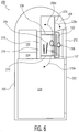
- FIG. 8 a practical implementation of the FXI is a waterproof configuration 240 designed for operation submerged in water. This version is particularly useful in decontamination and remediation of river bottoms and coastal waters by passing X-rays into material 148 to be irradiated.
- FIG. 8 shows X-rays 136 from an X-ray emitting surface of the anode (not shown) extend, typically below the depth shown, through an irradiation volume of material 148.
- the high intensity radiation degrades organic hydrocarbon contaminants into more benign compounds.
- a boat 242 contains a generator 190, a fuel tank 186, and a high voltage power supply 130. There is a crane and winch 246 mounted on the boat to allow raising and lowering the waterproof FXI 310.
- a cable 244 is connected between the winch and crane 246 and the FXI 310 to raise and lower the FXI 310, including raising it entirely out of the water.
- the winch and crane is capable of placing the FXI 310 on the deck of the boat 242.
- the waterproof FXI 310 may be nearly identical to the standard planar FXI 110, except that it is has fully waterproofed electrical connections (not shown).
- This radiation shield is made from overlapping strips of a rubberized material that has a high content of lead, tungsten, molybdenum, or bismuth. There is a plurality of layers of such strips disposed in such a fashion that one layer covers the slight gaps between strips on the adjacent layer.
- a radiation shield of this design is sufficiently flexible to allow the shield to conform to obstacles without compromising the radiation integrity of the system. The rubberized material is not damaged by exposure to water.
- FIG. 9 It is possible to build the FXI in a spherical geometry as shown in FIG. 9 . It is similar in construction to the cylindrical geometry version of the X-ray tube 109 of FIG. 1 except that it is curved in two dimensions instead of one. Operation is the same as the cylindrical FXI.
- the spherical FXI 250 is contained within a housing 252.
- a spherical cathode 258 which concentrically surrounds a spherical grid 256, which in turn concentrically surrounds a spherical anode 254.
- the interior volume of the spherical anode 254 is the irradiation volume 278.
- An electrical connection to the cathode 258 is provided via feedthrough 270 which contains the cathode terminal 272 that provides a connection to the cathode 258.
- An electrical connection is provided via feedthrough 266 for the grid 256 which contains the grid terminal 268 that provides a connection to the grid 256.
- An electrical connection is provided via feedthrough 262 for the anode 254 which contains the anode terminal 264 that provides a connection to the anode 254 via the internal anode lead 260.
- An inlet pipe 274 provides a means of introducing material 148 to be irradiated into the irradiation volume 278, and an outlet pipe 276 provides a means of egress for materials that have been irradiated.
- the cathode 258 is charged by an external high voltage power supply 130a, 130b or 130c, etc.
- the grid 256 is connected to the cathode 258 by a bias resistor (not shown) to establish a standoff condition.
- the grid terminal 264 is grounded, the electrons 134 flow to the anode 154.
- the electrons strike the anode 254, they produce an X-ray flux 136 in the irradiation volume 278..
- the anode 154 is connected to ground 164 by internal anode lead 260 and anode terminal 264 contained within anode feedthrough 262.
- the entire interior volume of the housing 252 is held at a vacuum 132 of typically 1 x 10⁻⁹ Torr (i.e., 1.33 x 10⁻⁷ pascals).
- the Flash X-ray Irradiator uses this principle in the decomposition of organic compounds. By breaking the bonds holding complex organics together, these compounds can be reduced to simpler, less hazardous and mostly benign compounds. An example of this is found in the decomposition of dioxin, which along with other higher organic compounds, cause pollution of the waterways. Dioxin is a heterocyclic organic compound with the chemical formula C 4 H 4 O 2 . Exposure to high energy radiation breaks this down to H 2 O, CO 2 and HCl.
- the Flash X-ray Irradiator can also be implemented in an underwater housing and used to decontaminate river bottoms in situ (without dredging). The quality of remediation is significantly higher as a result of the elimination of the release of plumes of contaminated material by the dredging process.
- the Flash X-Ray Irradiator in various configurations can be used in the areas of Decontamination and Remediation in applications such as sterilization of water, in-situ remediation of hydrocarbon contaminated soils (such as gas stations), safe decomposition of all known hydrocarbon compounds, volatile organic compounds (VOCs) polychlorinated biphenyls (PCBs), dioxins, sewage outfall treatment, stormwater runoff treatment, in-situ remediation of riverbed contamination, medical waste stream treatment, oil and chemical spill cleanup, organic dye contaminated runoff, biologically contaminated gaseous waste streams such as output air from biohazard research facilities and hospitals which may contain highly virulent species, decontamination of fish farming pens, decontamination of postal mail, decontamination of animal factory farm waste streams, sterilization of potable water, food processing waste treatment, sterilization of bilgewater of ocean-going vessels to prevent migration of alien biological species, sterilization of medical products, sterilization of pharmaceuticals, sterilization of large swimming pools, sterilization of food products, ir
- the applications can be further categorized into the four major sections of 1. Hydrocarbon Remediation, 2. Decontamination, 3. Sterilization and 4. Manufacturing.
- Hydrocarbon contaminated soils such as beneath gas stations and refineries:
- One of the largest environmental problems that he global community faces is contamination of the ground beneath gas stations, oil terminals, or any oil handling facility due to leaking tanks.
- Hundreds of millions of dollars are both spent and wasted in the U.S. due to the inefficient remediation techniques currently available.
- a portable system based on the Flash X-ray Irradiator technology is expected to be able to decompose all hydrocarbons in the soil either in situ or excavated from an average gas station in under one day. This compares favorably to the amount of time, often months to years, it currently takes to achieve the same end result.
- This reduction in remediation time leads to a dramatic savings in effective cost for the service stations, oil terminals or any oil handling facility.
- Volatile Organic Components Volatile Organic Components represent a large regulated class of environmental contaminants.
- the Flash X-ray Irradiator safely decomposes VOCs rapidly and economically. This class of environmental contaminants is very large as the U.S. Environmental Protection Agency has reported at least 487 contaminants.
- PCBs Polychlorinated Biphenyls
- PCBs Polychlorinated Biphenyls
- Dioxin is a heterocyclic organic compound with the chemical formula C 4 H 4 O 2 .
- Dioxins are a particularly noxious and toxic series of compounds. They are generally byproducts of other organic processes. Previous attempts to destroy dioxins by incineration have produced its own set of byproducts that are damaging the environment.
- Current scientific literature uses the name "dioxins” commonly for simplification to denote the chlorinated derivatives of dibenzo- p -dioxin, more precisely the polychlorinated dibenzodioxins (PCDDs).
- PCDDs polychlorinated dibenzodioxins
- the polychlorinated dibenzodioxins which can also be classified in the family of halogenated organic compounds (halocarbons), have been shown to bioaccumulate in humans and wildlife due to their lipophilic (the ability of a chemical compound to dissolve in fats, oils, lipids, and nonpolar solvents) properties, and are known teratogens, mutagens, and carcinogens.
- the Flash X-ray Irradiation process will efficiently decompose these dioxins into harmless compounds and gases.
- Sewage Treatment plants are not completely effective in the removal of organic and biological contaminants. Most sewage treatment plants have some form of treatment process at the end of the process cycle to address this problem. Many known technologies such as the commonly used ultraviolet treatment are energy-inefficient and maintenance-intensive and none achieve total decontamination. The sludge (sewage outfall) contaminates the area into which it is discharged. The Flash X-ray Irradiator has the capability to resolve these problems by completely sterilizing the sludge, thereby mitigating the issues associated with its disposal.
- Oil and Chemical Spill Cleanup Traditional approaches to oil spill cleanup are relatively crude. They consist of using floating booms to contain the spill and using slow-moving boats with specialized pickup systems (skimmers) to remove the oil from the surface of the water. However, these systems are only successful if promptly applied and used on calm water. With pumping velocities of 25,000 gallons per minute which allow for cleanup, the high volume processing capacity of the cylindrical Flash X-ray Irradiator changes the paradigm of oil and chemical spill mitigation.
- Organic Dye Contaminated Runoff Treatment Factories that either produce or use organic-based dyes represent another pollution source, which in some areas of the world constitutes the predominant source of pollution. Because these dyes (mostly used in fabric coloring and printing inks) are complex hydrocarbons, they can be readily decomposed into safe compounds for disposal.
- Flash X-ray Irradiator A novel application for the Flash X-ray Irradiator is in sterilizing the water in fish farming pens.
- the high throughput of the Flash X-ray Irradiator coupled with its high sterilizing efficiency offers a means to rescue this industry. Norway has had to cut down its production of farmed salmon due to contamination of the fish.
- the Flash X-ray Irradiator coupled with an efficient water pumping system will be effective in removing the biological contaminants, allowing farmers to produce a higher yield of healthy fish.
- the Flash X-ray Irradiation technology can sterilize water more effectively than currently-used chlorine and ultraviolet remediation technologies. Its ability to process large volumes of water and its low maintenance requirements make it the preferred technology for potable water treatment.
- the pipe that the water flows through during the irradiation cycle is a stainless shell thus complying with all regulatory requirements for potable water systems.
- the Flash X-ray Irradiator is available in standard sizes up to 1 meter internal diameter. Larger sizes can be accommodated.
- Flash X-ray Irradiator can effectively penetrate this market due to its lower operating cost and higher throughput.
- current systems using electron beams or X-rays can generate a beam current of about 2 Amperes.
- the similarly-sized Flash X-ray Irradiator system will produce a beam current in excess of 20,000 Amperes. This means that the time required to achieve the same level of processing is cut by a factor of 10,000. This factor, when combined with the significantly higher reliability, will solve the problem at a greatly reduced cost.
- Sterilization of Medical Products Surgical instruments, bandages, sutures, medical procedure kits and a wide array of other medical products which are routinely sterilized by exposure to 60 Cobalt can be treated with the Flash X-ray Irradiator.
- the systems for sterilization with 60 Cobalt are expensive and cumbersome.
- the Flash X-ray Irradiator can replace these systems with both lower installed and operating costs and with equal sterilization efficiency.
- Sterilization of Pharmaceuticals The same techniques for sterilization of medical products and other bio-decontamination applications can be applied to pharmaceutical production.
- a wide array of pharmaceutical products is currently sterilized using various radiation and electron-beam sources.
- the Flash X-ray Irradiator offers higher throughput and lower operating and installed costs than existing technologies.
- Sterilization of Food Products The same arguments for sterilization of medical products, and other bio-decontamination applications can be applied to the processing of food products. Irradiation has been shown to increase the shelf life of products, eliminate the need for refrigeration in some products (by killing the bacteria that cause spoilage), and increase the safety of packaged foods in general. The same set of advantages applies here as in other applications: higher throughput, lower operating and installed cost.
- the Flash X-ray Irradiator can combat air pollution caused by combustion gases from industrial plants. Typical byproducts of the decomposition of combustion gases are sulfur dioxide (SO 2 ) and nitrous oxides (NO x ).
- SO 2 sulfur dioxide
- NO x nitrous oxides
- the Flash X-ray Irradiator is capable of reformation of certain waste products, for instance cellulosic waste, a byproduct of paper-making, into higher order hydrocarbons.
- Asynchronous Pulse Modulator 130c ( Fig. 4B only) Input terminal 162 HV Output Terminal 170 Ground 164 Monitored ground 164a Energy Storage Capacitor 152 Circuit Capacitor 154 (a, b, c, d, etc.) Variable Capacitor 172a, 172b Resistor 158 (a, b, c, d, etc.) Current Measuring Shunt 168 Pulse Transformer 174 Cold Cathode Field Emission Triode 150 (a, b, c, d, etc.) Current Shunt Output Jacks 171 b, c, d Figure 5 Fig.
Landscapes
- Health & Medical Sciences (AREA)
- Life Sciences & Earth Sciences (AREA)
- Engineering & Computer Science (AREA)
- Environmental & Geological Engineering (AREA)
- Chemical & Material Sciences (AREA)
- Hydrology & Water Resources (AREA)
- General Health & Medical Sciences (AREA)
- Water Supply & Treatment (AREA)
- Veterinary Medicine (AREA)
- Public Health (AREA)
- Epidemiology (AREA)
- Animal Behavior & Ethology (AREA)
- Organic Chemistry (AREA)
- Toxicology (AREA)
- Soil Sciences (AREA)
- Biomedical Technology (AREA)
- Nutrition Science (AREA)
- Food Science & Technology (AREA)
- Optics & Photonics (AREA)
- Medicinal Chemistry (AREA)
- Molecular Biology (AREA)
- Physics & Mathematics (AREA)
- Polymers & Plastics (AREA)
- Plasma & Fusion (AREA)
- Apparatus For Disinfection Or Sterilisation (AREA)
- X-Ray Techniques (AREA)
- Amplifiers (AREA)
- Electron Sources, Ion Sources (AREA)
- Non-Silver Salt Photosensitive Materials And Non-Silver Salt Photography (AREA)
- Inks, Pencil-Leads, Or Crayons (AREA)
- Medicines Containing Antibodies Or Antigens For Use As Internal Diagnostic Agents (AREA)
Description
- The present invention relates to apparatus for irradiation of materials. The invention relates more particularly to an apparatus that produces a high speed X-ray pulse or pulses for irradiation of materials.
- Sterilization of various materials by irradiation with high-energy radiation (gamma and X-ray) is a well-established technology. High-energy irradiation can break molecular bonds in various materials and decompose the toxic compounds into more benign compounds. Gamma sterilization has been considered the norm up until now because of the high energy and fluence (amount of radiation delivered per unit of time) of the source. Use of X-ray irradiation for manufacturing purposes such as the manufacture of heat-shrink tubing for electronics is also known.
- For sterilization with gamma radiation, 60Cobalt has been the standard radioisotope of choice. 60Cobalt emits gamma rays at energies of 1.17 MeV and 1.33 MeV. The efficacy of radiation at these energies has been long established for these applications. One of the drawbacks to the use of 60Cobalt is that its higher energy line (1.33 MeV) is above the energy level at which radioactivity is induced. There is a need for an irradiation apparatus whose maximum energy output is below the threshold of 60Cobalt, so as to avoid the problem of inducing radioactivity in material being irradiated. It would further be desirable to provide an apparatus for irradiation that altogether avoids the use of radioisotopes, so as simplify operation and licensing, and eliminate the possibility of diversion of such radioisotopes for illegal purposes.
- Prior X-ray sources have not achieved a position of dominance due to the fact that although they can easily achieve higher energies, they have heretofore been unable to economically achieve the fluence of gamma sources. A need exists, therefore, for irradiation apparatus that can simultaneously achieve both the high energy and fluence necessary for practical sterilization, decontamination, and environmental remediation applications.
- The invention provides an apparatus for Flash X-ray irradiation of material, referred to in this description as a Flash X-ray Irradiator r (FXI) as defined in
claim 1. - The Flash X-ray Irradiator has a maximum energy output below the threshold of 60Cobalt, so as to avoid the problem of inducing radioactivity in material being irradiated. The Flash X-ray Irradiator also avoids the use of radioisotopes, as in the prior art use of 60Cobalt for irradiation, so as simplify operation and licensing, and eliminate the possibility of diversion of such radioisotopes for illegal purposes.
- Unlike conventional X-ray sources, the Flash X-ray Irradiator can simultaneously achieve both the high energy and fluence necessary for practical sterilization, decontamination, and environmental remediation applications. It can also be used for various manufacturing processes.
- In the drawing figures, in which like reference numerals refer to like parts:
-
FIG. 1 shows a cross-sectional view of the cylindrical version of the Flash X-Ray Irradiator, with cross hatching omitted for various parts such as the anode. -
FIG. 1A shows a detail view of thecircled region 117 inFIG. 1 showing the interaction of electrons with the anode to create X-rays in the transmission mode. -
FIG. 2 shows a cross-sectional view of the planar version of the Flash X-ray Irradiator. -
FIG. 2A shows a detail view of the circledregion 125 inFIG. 2 which is modified to include a supplementary energy storage capacitor. -
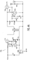
FIG. 3 shows a schematic diagram of a cascade voltage amplifier used a high voltage pulse power supply. -
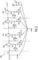
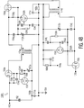
FIG. 4A shows a schematic diagram of a two-stage asynchronous pulse modulator used a high voltage pulse power supply. -
FIG. 4B shows a schematic diagram of a three-stage asynchronous pulse modulator used a high voltage pulse power supply. -
FIG. 5 shows an upper plan view in diagrammatic form of a cylindrical Flash X-ray Irradiator mounted in a standard shipping container and integrated with a turbo-jet engine powered generator and a high voltage power supply. -
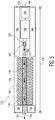
FIG. 6 shows a cross-sectional view from the left side of a planar Flash X-ray Irradiator integrated into a postal mailbox, with various thin parts shown as single lines and with cross-hatching omitted on various surfaces. -
FIG. 7 shows a side-plan view in diagrammatic form of a planar Flash X-ray Irradiator mounted on the underside of a truck, with associated equipment also mounted on the truck. -
FIG. 8 shows a side-plan view in diagrammatic form of an underwater version of the planar Flash X-Ray Irradiator suspended from a crane on a boat, with associated equipment also mounted on the boat. -
FIG. 9 shows a cross-sectional view of a spherical version of the Flash X-Ray Irradiator, with cross hatching omitted for various parts such as the anode. - For convenience, a list of drawing numbers and associated parts for
Figures 1-9 can be found near the end of this detailed description of the invention. -
FIGS. 1 and2 show two different embodiments of a Flash X-Ray Irradiator (FXI). An FXI is generally a transmission type X-ray tube. It is differentiated from the prior art by several features. The first is its electron gun, which, inFIG. 1 , comprises acathode 111 and agrid 113, and inFIG. 2 comprises acathode 112 and agrid 114. These electron guns can achieve current densities up to 80,000 Amps/cm2 in the pulse mode, which ultimately result in high levels of irradiation. For instance, the FXI can achieve high energy of typically 0.1 - 5 MeV, a high beam current of typically 50 KiloAmp - 1 MegaAmp pulses, a high fluence of typically 16 KiloGrey/pulse, and a repetition rate typically up to 100 Hz. - The Flash X-ray Irradiator 109 of
FIG. 1 may advantageously include a supplementaryenergy storage capacitor 124a which would be coaxially wound around thecathode 111. This allows local storage of substantially greater amounts of energy without changing the physical size of the Flash X-ray Irradiator 109. Similarly, a planar implementation of a supplementary energy storage capacitor may be advantageously incorporated in the planar Flash X-ray Irradiator 110. With reference toFIG. 2A , which is modified to include asupplementary storage capacitor 124b betweencathode support 144 and thecathode 112, for the same purpose as thesupplementary storage capacitor 124a ofFIG. 1 . - Referring to both
FIGS. 1 and2 , in operation, thecathode power supply FIGS. 3 or4A or 4B, respectively. A bias resistor (not shown) is connected between thecathode grid anode electrons 134 with a potential in excess of 23 kiloVolts are suddenly stopped, in this case by striking the anode. When they hit the anode, a mixture ofX-radiation 136 and secondary electrons (not shown) are liberated from an X-ray emitting surface of the anode in an isotropic fashion. Since the anode is thin in comparison to the penetration depth of the incident electrons, there is a preponderance of X-radiation transmitted from an electron-receiving surface of the anode, through the anode, to an irradiation volume beyond. - Referring to both
FIGS. 1 and2 , the thickness of the anode of theX-ray tube - Further, the cathode and grid are fabricated to extremely tight tolerances, typically on the order of 25 microns on any dimension, even if the structure is meters long. The
X-ray tube - Although not shown in
FIGS. 1 and2 ,X-ray tube - In
FIG. 2 , theanode 116 is preferably flat. However, theanode 116 can be formed in various shapes, such as arcuate in cross section as long as the X-ray emitting surface of theanode 116 is shaped so as to not enclose the irradiation volume. Preferably, the anode is thin, by which is meant that one dimension is much smaller than the other two orthogonal dimensions, and receives electrons from the cathode on one main surface and emits X-rays from a second, oppositely facing main surface. - For irradiating a
material 148, such material must pass through the irradiation volume mentioned above. This can occur in three general ways: (1) the material can be moved through a stationary irradiation volume; (2) the irradiation volume can be moved past stationary material; or (3) both the irradiation volume and material can move simultaneously. The embodiment ofFIG. 1 is particularly adapted to the first way (1), whereas the embodiment ofFIG. 2 is particularly adapted to the first (1) and second (2) ways. In this connection, as mentioned above, in the embodiment ofFIG. 2 , the X-ray emitting surface of theanode 116 is shaped so as to not enclose the irradiation volume. In contrast, in bothFIGS. 1 and9 , the irradiation volume is enclosed. -
FIG. 1A diagrammatically showselectrons 134 that strikeanode 117 on an electron-receiving surface of the anode. This results in an opposite, main X-ray emitting surface of theanode 117 emittingX-radiation 136 within the cylindrical inner volume of the anode. Similarly, inFIG. 2 ,electrons 134 that strikeanode 116 cause a lower-shown, X-ray emitting surface of the anode to emitX-rays 136 that extend, typically below the depth shown, through an irradiation volume ofmaterial 148. - The X-ray emitting surface of the anode 115 (
FIG. 1 ), 116 (FIG. 2 ) preferably has orthogonally oriented first and second dimensions of greater than 2 millimeters each. To achieve this, in the case ofFIG. 1 , the linear dimensions of the active portions of the cathode, grid and anode are the same; and in the case ofFIG. 2 , the length and width of the active portions of the cathode, grid and anode are the same. - The
electron gun 111, 113 (FIG. 1 ) or 112, 114 (FIG. 2 ), anode 115 (FIG. 1 ) or 116 (FIG. 2 ) and high voltagepulse power supply 130 are so constructed as to create sufficient X-radiation in the irradiation volume mentioned above to achieve a desired level of irradiation ofmaterial 148 in that volume. - Referring to both
FIGS. 1 and2 , to facilitate introduction of high voltage electrical signals through aconductive wall 137 to thecathode grid insulated feedthroughs anode insulated feedthroughs cathode grid - Referring to both
FIGS. 1 and2 as well to other figures herein showing FXI embodiments, the material to be irradiated 148 has motion relative to the irradiation volume and constitutes flowingmaterial 128 through the irradiation volume. - There are several critical conditions that must be met when designing a grid for a FXI. They are.
- (1) The grid-cathode spacing must be constant across the length of the grid. This is usually accomplished by placing the grid under high tension or building it with a rigid structure.
- (2) The number of elements in the grid must be high enough to ensure a constant and uniform electric field in the grid-cathode region.
- (3) There must be no sharp edges of burs anywhere in the grid structure, individual elements can be round, flat or high aspect-ratio elliptical shapes. All edges must be fully radiused. In this context, fully radiused means that the edge in question has a radius equal to half the thickness of the material.
- The actual implementation of these design rules is determined by the size of the grid being built.
- The
Cascade Voltage Amplifier 130a ofFIG. 3 provides a novel way to obtain high voltage pulses for operating the Flash X-Ray Irradiators described herein, and is far more reliable and compact than the Marx generator circuit traditionally used for generating high voltage pulses. The circuit of 130a is the preferred embodiment for generating high voltage pulses for the FXI system. - In the
first stage 135a, a negative high voltage power supply (not shown) is connected to input terminal 162 and is used to chargeenergy storage capacitor 152. Cold CathodeField Emission Triode 150a in conjunction withinductor 156a,resistor 158a,capacitor 154a andvariable resistor 160a has dual functions. They are used to both form the pulse and to amplify it by anywhere from 3dB to 10dB depending on the gain of thetube 150a as manufactured. Thevariable resistor 160a is used to set the standoff bias voltage of thetube 150a. Theinductor 156a is used to block DC components from reaching the grid oftube 150a. The RC network of 158a and 154a is used to create a time constant to delay the conduction of thetube 150a. -
Subsequent stages tubes - All stages of the circuit are connected to a
common RF ground 164 in accordance with good RF design practice. Acurrent shunt 168 makes possible a monitoredground return 164a. - The
inductor 156e is used to prevent reverse voltage from reaching the charging power supply. This may be augmented by a series diode (not shown) of appropriate voltage for additional protection. - The
current shunt 168 is an extremely low inductance low value resistor, typically in the 50 to 100 micro-Ohm range. It is necessary to apply a skin depth calculation to the output of this shunt present at thejack 171 a to obtain a corrected and accurate current reading. Thejack 171a is of a type that supports the anticipated bandwidth of the signal generated by thecurrent shunt 168 based on the rise time of such signal. The output signal of thecurrent shunt 168 is typically matched to 50 Ohms impedance. - It is noted that it is possible to reach higher voltage by adding additional stages in series with the main circuit. Care must be taken to ensure that the voltage ratings and insulation designs are commensurate with the voltages encountered. It is not uncommon to put a circuit of this type in an insulating oil tank for higher reliability.
- An alternative to the
Cascade Voltage Amplifier 130a ofFIG. 3 is theAsynchronous Pulse Modulator FIGS. 4A and4B . The following description of the Asynchronous Pulse Modulator refers to bothFIGS. 4A and4B . In these figures, in the first stage, a negative high voltage power supply (not shown) is connected toterminal 162. This power supply chargesenergy storage capacitor 152. A voltage-monitoring circuit consisting ofresistor 158e,capacitor 154e,resistor 158f,capacitor 154f,variable capacitor 172a and cold cathodefield emission triode 150f is used to detect the charge state ofenergy storage capacitor 152. This measurement is made using a capacitive voltage divider consisting is 154e, 154f and 172a. When the voltage across the divider reaches a preset limit (determined by the setting ofvariable capacitor 172a), Cold CathodeField Emission Triode 150f conducts and pulls the grid of cold cathodefield emission triode 150e to ground. This causes Cold CathodeField Emission Triode 150e to go into conduction which, in turn, dischargesenergy storage capacitor 152 to discharge in to the primary of thepulse transformer 174a. - The second stage starts at the secondary of the
pulse transformer 174a, which typically has a turns ratio in excess of 1:10. This transformer steps the voltage up to a desired value. This is detected by a second capacitive voltage divider consisting ofcapacitor 154g andvariable capacitor 172b. As is the case with the primary stage, when the network consisting ofcapacitor 154g,variable resistor 172b,resistor 158h,capacitor 154i,capacitor 154h, and Cold CathodeField Emission Triode 150h reaches a predetermined voltage, thetube 150h conducts, pulling the grid of Cold CathodeField Emission Triode 150g to ground and causes this triode to go into conduction, allowing the pulse present from the secondary of the pulse transformer 174 to reach the output terminal. - It is noted that
resistors 158e and 159g are bias resistors used to keep their respective Cold CathodeField Emission Triodes Field Emission Triodes - The
current shunt 168c is a extremely low inductance low value resistor, typically in the 50 to 100 micro-Ohm range. It is necessary to apply a skin depth calculation to the output of this shunt(s) present at the jack(s) 171 b or 171 c to obtain a corrected and accurate current reading. - It is possible to reach higher voltage by adding additional secondary stages in series with the main circuit as shown in
FIG. 4B . In the Asynchronous Pulse Modulator ofFIG. 4B , stages are separated bypulse transformers stage following transformer 174b is the same as the stage betweentransformers - As illustrated in
FIG. 5 , apractical configuration 176 of the Flash X-Ray Irradiator places acylindrical FXI 109 in astandard shipping container 192 with all its support equipment integrated. - In the preferred embodiment, a small turbo-
jet engine 188 is mounted to the floor of thecontainer 192. The rotating shaft of theengine 188 is connected to anelectrical generator 190 having an internal gearbox speed reducer. This configuration is well-known in the electric utility industry as a means for generating power to compensate for peak power surges. The exhaust of turbo-jet engine 188 is connected to aVenturi vacuum pump 180, which is, in turn connected to the input port of theFXI 109. This configuration ofengine 188, pump 180 andgenerator 190 makes use of both the motive power of the pump for running the generator and of the exhaust of the pump to power a Venturi vacuum pump.Fuel tanks 186 provide a local source of fuel to allow independent operation for some number of hours, which depends on the size of the jet engine and the fuel tanks. - The material to be irradiated 148 is drawn by suction into the
Venturi inlet port 182. This flowingmaterial 128 passes through thedevice 109 and is exposed to high-intensity X-rays 136 in the interior space of theFXI 109 and then exhausted through theoutput port 194. Thematerial 148 may be of any form which will flow through a pipe. A highvoltage power supply FXI 109. The high voltage power supply is powered by the output of theelectrical generator 190. - The
air inlet 198 draws in outside air and flows it over thegenerator 190 to cool saidgenerator 190 prior to this air entering theair inlet 198 of the turbo-jet engine 188. This arrangement promotes energy efficiency in operating the FXI. There is anair filter 199 located in theair inlet 198 to keep airborne dirt from entering the turbo-jet engine 188 andgenerator 190. - Because the
configuration 176 is mounted in astandard shipping container 192, it can be transported by tractor trailer, ship or air with great ease. - As illustrated in
FIG. 6 , apractical configuration 200 of the Flash X-Ray Irradiator places aFXI 110 ofFIG. 2 in a mail-receiving device. In use, a person opensdoor 226 as shown by dashed-line arrow 226a and places some mail orother items 137 in theinlet chute 204. When theinlet door 226 closes, theupper door 208 to theirradiation chamber 205 opens as shown by dashed-line arrow 208a and themail 137 drops into theirradiation chamber 205, and then theupper door 208 closes. TheX-ray tube 110 turns on and saturates themail 137 with high energy X-ray radiation such as that circled at 136. Adosage monitor 218 embedded in the rear wall of the chamber detects theirradiation 136, and when the irradiation has reached a satisfactory level, shuts off theX-ray tube 110. Thelower door 210 to theirradiation chamber 205 then opens as shown by dashed-line arrow 210a and the sterilizedmail 137 drops into thestorage bin 220 below to await collection by the postal carrier. Thelower door 210 then closes, and theconfiguration 200 resets for the next use. - The
upper door 208 is hinged and opens upward, while thelower door 210 is hinged and opens downward by actuators (not shown). There are seals on both theupper door 208 and thelower door 210 which ensure an air-tight seal when the door is closed, to prevent biological contaminants from entering thestorage bin 220. The storage bin may optionally be under slight positive pressure provided by thepressurizer 224 to further prevent secondary contamination of the mail. The sterilized mail is removed from the large front-access door 222. - A high
voltage power supply 130a etc. provides the operating voltages for theX-ray tube 110. TheX-ray tube 110 and theirradiation chamber 205 are surrounded with radiation shieldsfront shield 212,rear shield 216, left and right shields (not shown) andupper door 208 andlower door 210, which contain shielding. - The control circuitry will quarantine mail or
other items 137 in theirradiation chamber 205 if a preset minimum dosage ofX-rays 136 is not achieved, to prevent contamination of previously sterilized mail for any of several reasons. One such reason would be failure of the irradiation system, for any reason. Another reason is to prevent biotoxins contained in a shielded package from entering the storage bin. - The entire system may be housed in an enclosure that resembles a standard postal mailbox, vertical mail chutes as found in office and residential buildings, or mail slots as found in post offices and other locations.
- A
practical configuration 290 of the FXI is to mount it on the underside of a truck as shown inFIG. 7 . This configuration allows rapid decontamination of underground contamination inmaterial 148 withX-rays 136. This is particularly useful for remediation of leaking gasoline and oil tanks at gasoline filling stations, refineries and storage yards. - In
FIG. 7 , a preferablyplanar FXI 110, such as described in connection withFIG. 2 above, is mounted to the underside of atruck 292 of sufficient load-bearing capacity. TheFXI 110 is mounted to allow sufficient ground clearance when the truck is driven.X-rays 136 from an X-ray emitting surface of the anode (not shown) extend, typically below the depth shown, through an irradiation volume ofmaterial 148. - To prevent stray radiation from escaping from the
FXI 110, a flexiblemulti-layer radiation shield 234 may be mounted around the periphery of the FXI. This radiation shield is made from overlapping strips of a rubberized material that has a high content of lead, tungsten, molybdenum, or bismuth. There is a plurality of layers of such strips disposed in such a fashion that one layer covers the slight gaps between strips on the adjacent layer. A radiation shield of this design is sufficiently flexible to allow the shield to confirm to obstacles without compromising the radiation integrity of the system. The highvoltage power supply 130,generator 190 andfuel tank 186 are mounted on the bed of thetruck 292. - As shown in
FIG. 8 , a practical implementation of the FXI is awaterproof configuration 240 designed for operation submerged in water. This version is particularly useful in decontamination and remediation of river bottoms and coastal waters by passing X-rays intomaterial 148 to be irradiated.FIG. 8 shows X-rays 136 from an X-ray emitting surface of the anode (not shown) extend, typically below the depth shown, through an irradiation volume ofmaterial 148. - The high intensity radiation degrades organic hydrocarbon contaminants into more benign compounds.
- A
boat 242 contains agenerator 190, afuel tank 186, and a highvoltage power supply 130. There is a crane andwinch 246 mounted on the boat to allow raising and lowering thewaterproof FXI 310. Acable 244 is connected between the winch andcrane 246 and theFXI 310 to raise and lower theFXI 310, including raising it entirely out of the water. The winch and crane is capable of placing theFXI 310 on the deck of theboat 242. Thewaterproof FXI 310 may be nearly identical to the standardplanar FXI 110, except that it is has fully waterproofed electrical connections (not shown). - To prevent stray radiation from escaping, there is a flexible
multi-layer radiation shield 234 mounted around the periphery of the FXI. This radiation shield is made from overlapping strips of a rubberized material that has a high content of lead, tungsten, molybdenum, or bismuth. There is a plurality of layers of such strips disposed in such a fashion that one layer covers the slight gaps between strips on the adjacent layer. A radiation shield of this design is sufficiently flexible to allow the shield to conform to obstacles without compromising the radiation integrity of the system. The rubberized material is not damaged by exposure to water. - It is possible to build the FXI in a spherical geometry as shown in
FIG. 9 . It is similar in construction to the cylindrical geometry version of theX-ray tube 109 ofFIG. 1 except that it is curved in two dimensions instead of one. Operation is the same as the cylindrical FXI. - Referring to
FIG. 9 , thespherical FXI 250 is contained within ahousing 252. There is aspherical cathode 258 which concentrically surrounds aspherical grid 256, which in turn concentrically surrounds aspherical anode 254. The interior volume of thespherical anode 254 is theirradiation volume 278. An electrical connection to thecathode 258 is provided viafeedthrough 270 which contains thecathode terminal 272 that provides a connection to thecathode 258. An electrical connection is provided viafeedthrough 266 for thegrid 256 which contains thegrid terminal 268 that provides a connection to thegrid 256. An electrical connection is provided viafeedthrough 262 for theanode 254 which contains theanode terminal 264 that provides a connection to theanode 254 via theinternal anode lead 260. Aninlet pipe 274 provides a means of introducingmaterial 148 to be irradiated into theirradiation volume 278, and anoutlet pipe 276 provides a means of egress for materials that have been irradiated. - In operation, the
cathode 258 is charged by an external highvoltage power supply grid 256 is connected to thecathode 258 by a bias resistor (not shown) to establish a standoff condition. When thegrid terminal 264 is grounded, theelectrons 134 flow to the anode 154. When the electrons strike theanode 254, they produce anX-ray flux 136 in theirradiation volume 278.. The anode 154 is connected to ground 164 byinternal anode lead 260 andanode terminal 264 contained withinanode feedthrough 262. The entire interior volume of thehousing 252 is held at avacuum 132 of typically 1 x 10⁻⁹ Torr (i.e., 1.33 x 10⁻⁷ pascals). - In the case of bio-decontamination, no life-form can withstand exposure to radiation at the energies and fluences contemplated by the Flash X-ray Irradiator. An example of this is the Anthrax bacterium (Bacillus Anthracis). In recent years, as a result of the Anthrax attacks of 2001 in the United States, the use of high-energy radiation has become the standard for eradicating these bacteria. The Anthrax bacterium is killed with 100% reliability at a dosage of 16 KiloGreys. The high-energy radiation breaks bonds in the bacteria resulting in its destruction. These bacteria are regarded as the most resistant of all known bacteria, thus any treatment that is effective against them will also be effective against everything else.
- The Flash X-ray Irradiator uses this principle in the decomposition of organic compounds. By breaking the bonds holding complex organics together, these compounds can be reduced to simpler, less hazardous and mostly benign compounds. An example of this is found in the decomposition of dioxin, which along with other higher organic compounds, cause pollution of the waterways. Dioxin is a heterocyclic organic compound with the chemical formula C4H4O2. Exposure to high energy radiation breaks this down to H2O, CO2 and HCl. The Flash X-ray Irradiator can also be implemented in an underwater housing and used to decontaminate river bottoms in situ (without dredging). The quality of remediation is significantly higher as a result of the elimination of the release of plumes of contaminated material by the dredging process.
- The Flash X-Ray Irradiator in various configurations can be used in the areas of Decontamination and Remediation in applications such as sterilization of water, in-situ remediation of hydrocarbon contaminated soils (such as gas stations), safe decomposition of all known hydrocarbon compounds, volatile organic compounds (VOCs) polychlorinated biphenyls (PCBs), dioxins, sewage outfall treatment, stormwater runoff treatment, in-situ remediation of riverbed contamination, medical waste stream treatment, oil and chemical spill cleanup, organic dye contaminated runoff, biologically contaminated gaseous waste streams such as output air from biohazard research facilities and hospitals which may contain highly virulent species, decontamination of fish farming pens, decontamination of postal mail, decontamination of animal factory farm waste streams, sterilization of potable water, food processing waste treatment, sterilization of bilgewater of ocean-going vessels to prevent migration of alien biological species, sterilization of medical products, sterilization of pharmaceuticals, sterilization of large swimming pools, sterilization of food products, irradiation of plastics and elastomers for electronics, reformation of waste products.
- The applications can be further categorized into the four major sections of 1. Hydrocarbon Remediation, 2. Decontamination, 3. Sterilization and 4. Manufacturing.
- Hydrocarbon contaminated soils (such as beneath gas stations and refineries): One of the largest environmental problems that he global community faces is contamination of the ground beneath gas stations, oil terminals, or any oil handling facility due to leaking tanks. Hundreds of millions of dollars are both spent and wasted in the U.S. due to the inefficient remediation techniques currently available. A portable system based on the Flash X-ray Irradiator technology is expected to be able to decompose all hydrocarbons in the soil either in situ or excavated from an average gas station in under one day. This compares favorably to the amount of time, often months to years, it currently takes to achieve the same end result. This reduction in remediation time leads to a dramatic savings in effective cost for the service stations, oil terminals or any oil handling facility. A similar situation exists with in-situ remediation of contaminated riverbed, or sea bed or lake bed of coastal waters.
- Safe Decomposition of Hydrocarbon & Organic Compounds: The same technology and hardware used for hydrocarbon contaminated soils can be used to decompose all hydrocarbon compounds.
- Volatile Organic Components: Volatile Organic Compounds (VOCs) represent a large regulated class of environmental contaminants. The Flash X-ray Irradiator safely decomposes VOCs rapidly and economically. This class of environmental contaminants is very large as the U.S. Environmental Protection Agency has reported at least 487 contaminants.
- Polychlorinated Biphenyls: Polychlorinated Biphenyls (PCBs) are another environmental contaminant that is difficult to manage. While there has been a longstanding effort to remove these materials from the environment, the procedures are expensive and time-consuming. In many cases, the decision has been made to leave the PCBs in place as there has previously been no cost-effective method of removing and destroying them. In certain cases, Flash X-ray Irradiator technology can destroy the PCBs in situ, a capability which has never been available before.
- Dioxins: Dioxin is a heterocyclic organic compound with the chemical formula C4H4O2. Dioxins are a particularly noxious and toxic series of compounds. They are generally byproducts of other organic processes. Previous attempts to destroy dioxins by incineration have produced its own set of byproducts that are damaging the environment. Current scientific literature uses the name "dioxins" commonly for simplification to denote the chlorinated derivatives of dibenzo-p-dioxin, more precisely the polychlorinated dibenzodioxins (PCDDs). The polychlorinated dibenzodioxins, which can also be classified in the family of halogenated organic compounds (halocarbons), have been shown to bioaccumulate in humans and wildlife due to their lipophilic (the ability of a chemical compound to dissolve in fats, oils, lipids, and nonpolar solvents) properties, and are known teratogens, mutagens, and carcinogens. The Flash X-ray Irradiation process will efficiently decompose these dioxins into harmless compounds and gases.
- Sewage Outfall Treatment: Sewage treatment plants are not completely effective in the removal of organic and biological contaminants. Most sewage treatment plants have some form of treatment process at the end of the process cycle to address this problem. Many known technologies such as the commonly used ultraviolet treatment are energy-inefficient and maintenance-intensive and none achieve total decontamination. The sludge (sewage outfall) contaminates the area into which it is discharged. The Flash X-ray Irradiator has the capability to resolve these problems by completely sterilizing the sludge, thereby mitigating the issues associated with its disposal.
- Stormwater Runoff Treatment: The U.S. Environmental Protection Agency has recently mandated that all stormwater runoff be treated to remove all biological contamination. There is currently no technology available to efficiently perform this task. The Flash X-ray Irradiator can be produced in large quantities at sufficiently low cost to allow municipalities to install this technology to remediate this problem.
- Medical Waste Stream Treatment: Due to the ability of the Flash X-ray Irradiator to generate radiation fluxes in the range of 16 KiloGreys per pulse, it is practical to consider the use of this technology to sterilize waste streams from hospitals to completely eliminate any pathogens. It is anticipated that the use of this technology would eliminate the need for special handling and disposal of medical wastes.
- Oil and Chemical Spill Cleanup: Traditional approaches to oil spill cleanup are relatively crude. They consist of using floating booms to contain the spill and using slow-moving boats with specialized pickup systems (skimmers) to remove the oil from the surface of the water. However, these systems are only successful if promptly applied and used on calm water. With pumping velocities of 25,000 gallons per minute which allow for cleanup, the high volume processing capacity of the cylindrical Flash X-ray Irradiator changes the paradigm of oil and chemical spill mitigation.
- Organic Dye Contaminated Runoff Treatment: Factories that either produce or use organic-based dyes represent another pollution source, which in some areas of the world constitutes the predominant source of pollution. Because these dyes (mostly used in fabric coloring and printing inks) are complex hydrocarbons, they can be readily decomposed into safe compounds for disposal.
- Biologically Contaminated Gaseous Waste Stream Treatment: Output air from biohazard research facilities and infectious wards in hospitals contain highly virulent species which must be killed before the air is exhausted into the atmosphere. The cylindrical version of the Flash X-ray Irradiators when coupled with a high velocity air handling system is well suited for this application. The same system used for stormwater runoff treatment and similar applications can be effectively used for this application.
- Decontamination of Fish Farming Pens: A novel application for the Flash X-ray Irradiator is in sterilizing the water in fish farming pens. The high throughput of the Flash X-ray Irradiator coupled with its high sterilizing efficiency offers a means to rescue this industry. Norway has had to cut down its production of farmed salmon due to contamination of the fish. The Flash X-ray Irradiator coupled with an efficient water pumping system will be effective in removing the biological contaminants, allowing farmers to produce a higher yield of healthy fish.
- Decontamination of Postal Mail: Following the U.S. cases of Anthrax in 2001 and 2002, it was realized that postal mail was extremely vulnerable to bio-contamination. Many institutions in the U.S. have already installed irradiation systems to decontaminate their incoming postal mail. To achieve decontamination of mail, the planar Flash X-ray Irradiator configuration, a flat panel irradiator mounted over a conveyor belt, works best. The panel can be several meters wide and the belt speed is high. This application is similar to the food irradiation application, in that the significantly higher beam current of the Flash X-ray Irradiation technology will allow substantially higher throughput and lower operating costs. There are many more institutions that would benefit from adding this technology such as banks, credit card companies, insurance companies, or other organizations that handle large volumes of incoming mail.
- Decontamination of Animal Factory Farm Waste Streams: A single large pig farm with 500,000 pigs produces more waste on a daily basis than the population of 10 million on the entire island of Manhattan in New York. At one time, factory farms were located in remote areas and the waste was either stored in large retention ponds or injected into the ground. The expansion of urban areas has begun to encroach on the areas where factory farms are located. The odors associated with these farms are substantial and the health risks are enormous. The potential for groundwater contamination by deadly pathogens being introduced into the groundwater is an actual threat. Many phosphate contaminated waste streams can be treated using the Flash X-ray Irradiator. Both types of the Flash X-ray Irradiation system, cylindrical and planar, will be useful in this field. The cylindrical irradiator will be used in permanent and portable installations.
- Sterilization of Potable Water: Providing clean, fresh water is a critical issue in every country. The Flash X-ray Irradiation technology can sterilize water more effectively than currently-used chlorine and ultraviolet remediation technologies. Its ability to process large volumes of water and its low maintenance requirements make it the preferred technology for potable water treatment. The pipe that the water flows through during the irradiation cycle is a stainless shell thus complying with all regulatory requirements for potable water systems. The Flash X-ray Irradiator is available in standard sizes up to 1 meter internal diameter. Larger sizes can be accommodated.
- Food Processing: Commercial irradiation of food products is already a well-established process. The Flash X-ray Irradiator can effectively penetrate this market due to its lower operating cost and higher throughput. For example, current systems using electron beams or X-rays can generate a beam current of about 2 Amperes. By comparison, the similarly-sized Flash X-ray Irradiator system will produce a beam current in excess of 20,000 Amperes. This means that the time required to achieve the same level of processing is cut by a factor of 10,000. This factor, when combined with the significantly higher reliability, will solve the problem at a greatly reduced cost.
- Sterilization of Bilgewater of Ocean-going Vessels: In order to prevent and treat the effects of migration of foreign biological species into the territorial waters of any other country, the Flash X-ray Irradiator can be installed on cargo ships. This is an area that has received much attention in the environmental community. Cargo ships using seawater for ballast are required, in the U.S. and many other countries, to decontaminate ballast water prior to dumping at the destination port. Dumping of contaminated ballast has been proven to introduce harmful alien species of flora and fauna into destinations waters, with devastating results. So, there is a great need for the FXI technology.
- Sterilization of Medical Products: Surgical instruments, bandages, sutures, medical procedure kits and a wide array of other medical products which are routinely sterilized by exposure to 60Cobalt can be treated with the Flash X-ray Irradiator. The systems for sterilization with 60Cobalt are expensive and cumbersome. The Flash X-ray Irradiator can replace these systems with both lower installed and operating costs and with equal sterilization efficiency.
- Sterilization of Pharmaceuticals: The same techniques for sterilization of medical products and other bio-decontamination applications can be applied to pharmaceutical production. A wide array of pharmaceutical products is currently sterilized using various radiation and electron-beam sources. In this application, the Flash X-ray Irradiator offers higher throughput and lower operating and installed costs than existing technologies.
- Sterilization of Large Swimming Pools: Swimming pools are subject to a large number of bio-contaminants including by not limited to urine, feces, blood, other bodily fluids and other random contaminants. While chlorine is traditionally used for decontamination of swimming pools, it is expensive, emits an unpleasant odor and chlorine dispensing systems require constant maintenance. Swimmers frequently find the residual smell of chlorine offensive, and bathing suits can decompose due to the acidic nature of the swimming pool water. Further, the human eye is susceptible to extreme irritation from chlorine. All of these problems can be mitigated by the use of a high throughput Flash X-ray Irradiator.
- Sterilization of Food Products: The same arguments for sterilization of medical products, and other bio-decontamination applications can be applied to the processing of food products. Irradiation has been shown to increase the shelf life of products, eliminate the need for refrigeration in some products (by killing the bacteria that cause spoilage), and increase the safety of packaged foods in general. The same set of advantages applies here as in other applications: higher throughput, lower operating and installed cost.
- Irradiation of Plastics and Elastomers for Electronics: There are many applications of irradiated plastics in electronic manufacturing. The largest application is the production of "heat-shrink" tubing by X-ray radiation-induced cross-polymerization. The Flash X-ray Irradiator technology can allow significantly higher production rates while simultaneously reduce manufacturing costs.
- Reformation of Waste Products: The Flash X-ray Irradiator can combat air pollution caused by combustion gases from industrial plants. Typical byproducts of the decomposition of combustion gases are sulfur dioxide (SO2) and nitrous oxides (NOx). The Flash X-ray Irradiator is capable of reformation of certain waste products, for instance cellulosic waste, a byproduct of paper-making, into higher order hydrocarbons.
- Many of the foregoing applications of the X-Ray Irradiator relate to areas of long-felt and substantial need that lack a solution comparable to that of the X-Ray Irradiator. For instance, the problems associated with using the radioisotope 60Cobalt for irradiation, as mentioned above, persist; and conventional X-ray sources lack the fluence necessary for practical sterilization, decontamination, environmental remediation and manufacturing applications.
- The following is a list of drawing reference and associated parts for each figure, for convenience of reference:
Figures 1 and2 Fig. 1 Fig. 2 Flash X-ray Irradiator 109 110 Cathode 111 112 Grid 113 114 Grid electrical lead 114a Anode 115 116 Anode Thin Section Region 117 Cathode Feedthrough 118 Grid feedthrough 120 Radiation Shield 122 Supplementary Energy Storage Capacitor 124a 124b Circled region in Fig. 2 125 Pipe Flange 126 Flowing Material 128 128 Power Supply 130 Vacuum Region 132 Electrons 134 X-rays 136 Housing 137 138 Cathode Electrical Lead 140 Grid Electrical Lead 142 Cathode Support 144 Pipe 146 Material to Be Irradiated 148 Figure 1A Fig. 1A Anode 117 Electrons 134 X-rays 136 Figure 2A Fig. 2A Modification of circled region in Fig. 2 125 Cathode 112 Supplemental Energy Storage Capacitor 124b Electrons 134 Cathode support 144 Figure 3 Fig. 3 Cascade Voltage Amplifier 130a Cold Cathode Field Emission Triode 150 (a, b, c, d, etc.) Energy Storage Capacitor 152 Circuit Capacitor 154 (a, b, c, d, etc.) Inductor 156 Fixed Resistor 158 (a, b, c, d, etc.) Variable Resistor 160 (a, b, c, d, etc.) Input terminal 162 Ground 164 Monitored ground 164a Current Measuring Shunt 168 HV Output Terminal 170 Current Shunt Output Jack 171a Figures 4A and4B Figs. 4A &4B Asynchronous Pulse Modulator 130b ( Fig. 4A only)Asynchronous Pulse Modulator 130c ( Fig. 4B only)Input terminal 162 HV Output Terminal 170 Ground 164 Monitored ground 164a Energy Storage Capacitor 152 Circuit Capacitor 154 (a, b, c, d, etc.) Variable Capacitor 172a, 172b Resistor 158 (a, b, c, d, etc.) Current Measuring Shunt 168 Pulse Transformer 174 Cold Cathode Field Emission Triode 150 (a, b, c, d, etc.) Current Shunt Output Jacks 171 b, c, d Figure 5 Fig. 5 Vehicle-mounted configuration 176 Flash X-ray Irradiator 178 HV Power Supply 130 ("a" or "b") Venturi 180 Venturi Inlet 182 Venturi Outlet 184 Fuel Tank 186 Turbo-Jet Engine 188 Generator 190 Standard Shipping Container 192 System Output 194 Dimension 196 X-rays 136 Material Flowing through Device 128 Material to be Irradiated 148 Air Inlet 198 Air Filter 199 Figure 6 Fig. 6 Configuration 200 Housing 202 Mail Chute Inlet 204 Irradiation Chamber 205 FXI 206 Upper Door 208 Lower Door 210 Front Shield 212 Side Shield 214 Rear Shield 216 Dosage Monitor 218 Storage Bin 220 Access Door 222 Pressurizer 224 HVPS 130 X-rays 136 Mail Being Irradiated 137 Inlet Door 226 Figure 7 Fig. 7 Configuration 290 Truck or tracked vehicle 292 FXI 110 HVPS 130 X-rays 136 Flexible Radiation Shield 234 Generator 190 Fuel Tank 186 X-rays 136 Material to Be Irradiated 148 Figure 8 Fig. 8 Configuration 240 Boat 242 Flexible radiation shield 234 Generator 190 Fuel Tank 186 FXI in Underwater Housing 310 HVPS 130 Interconnecting Cable 244 Crane & Winch 246 GPS Positioning System 248 X-rays 136 Material to Be Irradiated 148 Figure 9 Fig. 9 Spherical FXI 250 Housing 252 Anode 254 Grid 256 Cathode 258 Internal Anode Lead 260 Anode Feedthrough 262 Anode Terminal 264 Grid Feedthrough 266 Grid Terminal 268 Cathode Feedthrough 270 Cathode Terminal 272 Material to be irradiated 148 Vacuum 132 Electrons 134 X-rays 136 Inlet Pipe 274 Outlet Pipe 276 Irradiation Volume 278 Radiation Shield 280 HVPS 130 Ground 164 - The scope of the claims should not be limited by the preferred embodiments and examples, but should be given the broadest interpretation consistent with the description as a whole.
Claims (16)
- An apparatus for Flash X-ray irradiation of material, comprising:a) a Flash X-ray source comprising an electron source (111,112) and an anode (115, 116);b) the electron source comprising a field-emission cold-cathode having an electron emitting surface, and a grid (113, 114) for controlling electron flow from the cathode to the anode; an electrical connection for biasing the grid;c) the anode having an electron-receiving main surface and an X-ray emitting, oppositely facing main surface; the X-ray emitting surface emitting X-radiation into an irradiation volume (128);d) the X-ray emitting surface of the anode having orthogonally oriented first and second dimensions of greater than 2 millimeters each;e) a high voltage pulse power supply for powering the Flash X-ray source; the high voltage pulse power supply including an input terminal (162) and an output terminal (170) and a circuit including one or more cold cathode field emission electron triodes (150a,150b,150c,150d;150e,150g) between the input terminal and the output terminal;f) the electron source, anode and high voltage pulse power supply creating X-radiation in said irradiation volume to irradiate material (148) in said volume, whereby said material is ionized and molecular bonds in organic compounds contained in said material are broken; andg) a vacuum housing for the cathode, grid and anode of the Flash X-ray source maintained at a vacuum (132).
- The apparatus of claim 1, further comprising means for causing said material to pass through said irradiation volume.
- The apparatus of claim 2, wherein:a) the anode has an elongated cylindrical shape with a cylindrical interior, with said irradiation volume being in the cylindrical interior of said anode; said anode being formed of a pipe having relatively thick first and second ends between which ends exists an integral, relatively thin central region containing the electron-receiving main surface;b) the cathode has an elongated cylindrical shape;c) the grid has a cylindrical shape and acts as a gate interposed between said cathode and said anode; andd) the cathode is axially symmetric to and encircles said anode and said grid.
- The apparatus of claim 3, wherein a supplementary energy storage capacitor is positioned on the side of the cathode facing away from the grid; said capacitor being located within the vacuum housing with the cathode.
- The apparatus of claim 3, wherein:a) the means for causing said material to pass through said irradiation volume comprises a vehicle-mounted vacuum pump; andb) the high voltage pulse power supply has means for connection to a vehicle-mounted electrical generator.
- The apparatus of claim 5, wherein:c) the generator and vacuum pump are powered by a turbo-jet engine; andd) the turbo-jet takes in air that flows over the generator so as to cool the generator.
- The apparatus of claim 6, wherein the vacuum pump is a Venturi pump.
- The apparatus of claim 2, wherein:a) the X-ray emitting surface of the anode is shaped without a closed loop and is shaped so as to avoid enclosing that portion of the irradiation volume normal to the X-ray emitting surface of the anode; andb) the means for causing said material to pass through said irradiation volume comprises a vehicle for transporting said Flash X-ray source in such a way as to cause said irradiation volume to pass through in-situ material.
- The apparatus of claim 8, wherein the anode, grid and cathode are flat.
- The apparatus of claim 8, wherein the Flash X-ray source is adapted for underwater use with said X-ray emitting surface predominantly facing downward.
- The apparatus of claim 10, wherein the means for causing said material to pass through said irradiation volume includes means for vertically and horizontally positioning said X-ray emitting surface above material to be irradiated.
- The apparatus of claim 2, wherein:a) the X-ray emitting surface of the anode is shaped without a closed loop and is shaped so as to avoid enclosing that portion of the irradiation volume normal to the X-ray emitting surface of the anode; andb) the means for causing said material to pass through said irradiation volume comprises a chute for receiving gravity-fed items; the chute containing said Flash X-ray source, having lateral sides and having alternately openable upper and lower doors for receiving the items within the irradiation volume; and the irradiation volume containing a dosage sensor for determining when a sufficient dosage of X-radiation has occurred within the irradiation volume.
- The apparatus of claim 1, wherein;a) the X-ray emitting surface of the anode is shaped without a closed loop and is shaped so as to avoid enclosing that portion of the irradiation volume normal to the X-ray emitting surface of the anode; andb) wherein a supplementary energy storage capacitor is positioned on the side of the cathode facing away from the grid; said capacitor being located within the vacuum housing with the cathode.
- The apparatus of claim 1, wherein the high voltage pulse power supply provides high voltage pulses in the range of 1 to 100 nanoseconds.
- The apparatus of claim 1, wherein the cold-cathode and grid of the electron source forms an electron gun that is constructed in such a way as to have the capability to achieve current densities of up to 80,000 Amps per square centimeter.
- The apparatus of any of the preceding claims, wherein said vacuum is on the order of 1.33 x 10⁻⁷ pascals.
Priority Applications (2)
| Application Number | Priority Date | Filing Date | Title |
|---|---|---|---|
| SI200931462A SI2501437T1 (en) | 2008-05-16 | 2009-05-18 | Flash x-ray irradiator |
| HRP20160861TT HRP20160861T1 (en) | 2008-05-16 | 2016-07-13 | Flash x-ray irradiator |
Applications Claiming Priority (2)
| Application Number | Priority Date | Filing Date | Title |
|---|---|---|---|
| US12784508P | 2008-05-16 | 2008-05-16 | |
| PCT/US2009/044410 WO2009140697A1 (en) | 2008-05-16 | 2009-05-18 | Flash x-ray irradiator |
Publications (3)
| Publication Number | Publication Date |
|---|---|
| EP2501437A1 EP2501437A1 (en) | 2012-09-26 |
| EP2501437A4 EP2501437A4 (en) | 2013-08-07 |
| EP2501437B1 true EP2501437B1 (en) | 2016-04-13 |
Family
ID=41316159
Family Applications (1)
| Application Number | Title | Priority Date | Filing Date |
|---|---|---|---|
| EP09747778.0A Active EP2501437B1 (en) | 2008-05-16 | 2009-05-18 | Flash x-ray irradiator |
Country Status (14)
| Country | Link |
|---|---|
| US (1) | US8019047B2 (en) |
| EP (1) | EP2501437B1 (en) |
| AU (1) | AU2009246084C1 (en) |
| BR (1) | BRPI0924249A2 (en) |
| CA (1) | CA2754622C (en) |
| DK (1) | DK2501437T3 (en) |
| ES (3) | ES2581390T3 (en) |
| HR (1) | HRP20160861T1 (en) |
| HU (1) | HUE030327T2 (en) |
| MX (1) | MX2011010276A (en) |
| PL (1) | PL2501437T3 (en) |
| PT (1) | PT2501437T (en) |
| SI (1) | SI2501437T1 (en) |
| WO (1) | WO2009140697A1 (en) |
Families Citing this family (15)
| Publication number | Priority date | Publication date | Assignee | Title |
|---|---|---|---|---|
| CA2799645C (en) * | 2010-07-01 | 2017-04-18 | Advanced Fusion Systems Llc | Method and system for inducing chemical reactions by x-ray irradiation |
| CA2809883C (en) | 2010-10-05 | 2016-10-04 | Advanced Fusion Systems Llc | High voltage high current regulator circuit |
| CN103503110A (en) * | 2011-06-08 | 2014-01-08 | 康姆艾德控股公司 | X-ray emitter |
| AT12862U1 (en) * | 2011-08-05 | 2013-01-15 | Plansee Se | ANODE WITH LINEAR MAIN CIRCUIT DIRECTION |
| GB201303517D0 (en) * | 2013-02-27 | 2013-04-10 | Enxray Ltd | Apparatus for the generation of low-energy x-rays |
| US20150343367A1 (en) * | 2014-05-27 | 2015-12-03 | Edward Allen Zdunek | CO2 modification |
| US20150343380A1 (en) * | 2014-05-28 | 2015-12-03 | Edward Allen Zdunek | CO2 modification |
| US9981056B2 (en) * | 2015-02-27 | 2018-05-29 | Mazra Incorporated | Air treatment system |
| WO2017207383A1 (en) * | 2016-05-31 | 2017-12-07 | Koninklijke Philips N.V. | Apparatus for generating x-rays |
| PL3527230T3 (en) * | 2018-02-20 | 2024-08-05 | Bühler AG | Device and method for pasteurising and/or sterilising particulate material |
| JP6637569B1 (en) * | 2018-10-17 | 2020-01-29 | 浜松ホトニクス株式会社 | Flash lamp and flash lamp manufacturing method |
| EP3933881A1 (en) | 2020-06-30 | 2022-01-05 | VEC Imaging GmbH & Co. KG | X-ray source with multiple grids |
| US11623196B1 (en) | 2021-10-22 | 2023-04-11 | Advanced Fusion Systems Llc | Universal chemical processor with radioisotope source |
| US20230129947A1 (en) | 2021-10-22 | 2023-04-27 | Advanced Fusion Systems Llc | Advanced Beneficiation Process for Beneficiation, Mobilization, Extraction, Separation, and Concentration of Mineralogical Resources |
| US11471848B1 (en) | 2021-10-22 | 2022-10-18 | Advanced Fusion Systems Llc | Universal chemical processor |
Family Cites Families (16)
| Publication number | Priority date | Publication date | Assignee | Title |
|---|---|---|---|---|
| US2984751A (en) | 1958-07-28 | 1961-05-16 | Thompson Ramo Wooldridge Inc | Integral turbine-generator unit |
| GB1166051A (en) * | 1966-06-22 | 1969-10-01 | Atomic Energy Authority Uk | Improvements in or relating to Flash X-Ray Generation Methods and Apparatus |
| US3527942A (en) | 1967-11-09 | 1970-09-08 | Atlantic Richfield Co | Automatic sample changer for positioning a plurality of pellets in an x-ray analyzer |
| US4151419A (en) | 1977-10-20 | 1979-04-24 | The United States Of America As Represented By The United States Department Of Energy | Solids irradiator |
| US4396580A (en) | 1981-03-18 | 1983-08-02 | Avco Everett Research Laboratory, Inc. | Fluid-dynamic means for efficaceous use of ionizing beams in treating process flows |
| US4670894A (en) * | 1985-05-20 | 1987-06-02 | Quantum Diagnostics Ltd. | X-ray source employing cold cathode gas discharge tube with collimated beam |
| US4723263A (en) | 1985-05-20 | 1988-02-02 | Quantum Diagnostics, Ltd. | X-ray source |
| US4950962A (en) | 1985-05-20 | 1990-08-21 | Quantum Diagnostics, Ltd. | High voltage switch tube |
| US5323442A (en) * | 1992-02-28 | 1994-06-21 | Ruxam, Inc. | Microwave X-ray source and methods of use |
| US5311566A (en) | 1992-09-22 | 1994-05-10 | The Titan Corporation | In-situ x-ray treatment of organically contaminated material |
| DE19532129A1 (en) * | 1995-08-31 | 1997-03-06 | Clouth Gummiwerke Ag | System for actively reducing rotational irregularities of a shaft, in particular the drive shaft of an internal combustion engine, and method therefor |
| US6320935B1 (en) | 2000-02-28 | 2001-11-20 | X-Technologies, Ltd. | Dosimeter for a miniature energy transducer for emitting X-ray radiation |
| US7447298B2 (en) | 2003-04-01 | 2008-11-04 | Cabot Microelectronics Corporation | Decontamination and sterilization system using large area x-ray source |
| JP4786533B2 (en) | 2003-06-17 | 2011-10-05 | エックス−レイ オプティカル システムズ インコーポレーテッド | Movable permeability barrier for X-ray analysis of pressurized samples |
| US7274772B2 (en) * | 2004-05-27 | 2007-09-25 | Cabot Microelectronics Corporation | X-ray source with nonparallel geometry |
| US9036765B2 (en) | 2006-05-30 | 2015-05-19 | Advanced Fusion Systems Llc | Method and system for inertial confinement fusion reactions |
-
2009
- 2009-05-18 ES ES09747778.0T patent/ES2581390T3/en active Active
- 2009-05-18 EP EP09747778.0A patent/EP2501437B1/en active Active
- 2009-05-18 CA CA2754622A patent/CA2754622C/en active Active
- 2009-05-18 AU AU2009246084A patent/AU2009246084C1/en active Active
- 2009-05-18 SI SI200931462A patent/SI2501437T1/en unknown
- 2009-05-18 PL PL09747778.0T patent/PL2501437T3/en unknown
- 2009-05-18 HU HUE09747778A patent/HUE030327T2/en unknown
- 2009-05-18 PT PT97477780T patent/PT2501437T/en unknown
- 2009-05-18 MX MX2011010276A patent/MX2011010276A/en active IP Right Grant
- 2009-05-18 DK DK09747778.0T patent/DK2501437T3/en active
- 2009-05-18 US US12/467,974 patent/US8019047B2/en active Active
- 2009-05-18 WO PCT/US2009/044410 patent/WO2009140697A1/en active Application Filing
- 2009-11-16 ES ES09845045.5T patent/ES2635295T3/en active Active
- 2009-11-16 ES ES16191333.0T patent/ES2692768T3/en active Active
- 2009-11-16 BR BRPI0924249A patent/BRPI0924249A2/en not_active Application Discontinuation
-
2016
- 2016-07-13 HR HRP20160861TT patent/HRP20160861T1/en unknown
Also Published As
| Publication number | Publication date |
|---|---|
| ES2635295T3 (en) | 2017-10-03 |
| HRP20160861T1 (en) | 2016-09-23 |
| PT2501437T (en) | 2016-07-13 |
| CA2754622A1 (en) | 2009-11-19 |
| AU2009246084A1 (en) | 2012-02-16 |
| EP2501437A1 (en) | 2012-09-26 |
| AU2009246084B2 (en) | 2012-11-15 |
| BRPI0924249A2 (en) | 2019-09-24 |
| PL2501437T3 (en) | 2016-10-31 |
| ES2692768T3 (en) | 2018-12-05 |
| MX2011010276A (en) | 2011-10-24 |
| US8019047B2 (en) | 2011-09-13 |
| SI2501437T1 (en) | 2016-08-31 |
| EP2501437A4 (en) | 2013-08-07 |
| AU2009246084C1 (en) | 2014-02-13 |
| US20090285362A1 (en) | 2009-11-19 |
| HUE030327T2 (en) | 2017-05-29 |
| CA2754622C (en) | 2013-11-19 |
| DK2501437T3 (en) | 2016-08-01 |
| ES2581390T3 (en) | 2016-09-05 |
| WO2009140697A1 (en) | 2009-11-19 |
| WO2009140697A8 (en) | 2009-12-23 |
Similar Documents
| Publication | Publication Date | Title |
|---|---|---|
| EP2501437B1 (en) | Flash x-ray irradiator | |
| US5457269A (en) | Oxidizing enhancement electron beam process and apparatus for contaminant treatment | |
| Borrely et al. | Radiation processing of sewage and sludge. A review | |
| EP0659297B1 (en) | Toxic remediation system and method | |
| CN112517599B (en) | Medical waste treatment device and treatment method thereof | |
| DE19619022C2 (en) | Water tank arrangement | |
| US20140339147A1 (en) | Compact biocidal water purification system | |
| KR100551715B1 (en) | Method for removal of polycyclic aromatic hydrocarbons(pahs) using irradiation | |
| KR100996382B1 (en) | A method of disinfection of pathogens and degradation of recalcitrant toxic organic chemicals by radiation with sulfate radicals | |
| KR102402357B1 (en) | Imported aquatic products quarantine facility with breeding water purification and filtration equipment | |
| Gray et al. | Environmental radiolysis for soil and sediment treatment: a review of chemistry, design, and economic issues | |
| RU3060U1 (en) | RADIATION-TECHNOLOGICAL COMPLEX | |
| Qadir et al. | Health Care Waste: Pollution Potential from Generation to Disposal, Management, and Treatment | |
| WO2003016222A1 (en) | Energy-based process for fluid treatment and system therefor | |
| Lubicki et al. | Removal of volatile organic compounds in water using low-energy electron beam | |
| Iacoboni et al. | A new semi-mobile plant for radiation processing of waste | |
| IACOBONI et al. | A NEW SEMI-MOBILE PLANT FOR XA9847735 RADIATION PROCESSING OF WASTE | |
| JP2001009480A (en) | Method for removing harmful substance in ground water | |
| KR100731802B1 (en) | Method of sterilization from wastewater disposal treatment using electron beam irradiation | |
| Pachan et al. | Use of accelerators for environmental protection | |
| JP2001087753A (en) | Device for making harmful chlorine-containing organic material harmless | |
| Curry et al. | Commercial applications of electron beam advanced oxidation technology | |
| Godio et al. | AquaConSoil 2013–List of Papers | |
| Lubicki et al. | Decomposition of chloroform and trichloroethylene in deionized water with the use of low voltage electron beam | |
| KR20040010902A (en) | Purification apparatus and method for flushing water/extracted gas of contaminated soil and/or contaminated groundwater by electron beam irradiation |
Legal Events
| Date | Code | Title | Description |
|---|---|---|---|
| PUAI | Public reference made under article 153(3) epc to a published international application that has entered the european phase |
Free format text: ORIGINAL CODE: 0009012 |
|
| 17P | Request for examination filed |
Effective date: 20111118 |
|
| AK | Designated contracting states |
Kind code of ref document: A1 Designated state(s): AT BE BG CH CY CZ DE DK EE ES FI FR GB GR HR HU IE IS IT LI LT LU LV MC MK MT NL NO PL PT RO SE SI SK TR |
|
| DAX | Request for extension of the european patent (deleted) | ||
| RAP1 | Party data changed (applicant data changed or rights of an application transferred) |
Owner name: ADVANCED FUSION SYSTEMS LLC |
|
| A4 | Supplementary search report drawn up and despatched |
Effective date: 20130705 |
|
| RIC1 | Information provided on ipc code assigned before grant |
Ipc: A61N 5/10 20060101AFI20130701BHEP Ipc: H01J 35/04 20060101ALI20130701BHEP Ipc: H01J 35/22 20060101ALI20130701BHEP Ipc: H05G 1/24 20060101ALI20130701BHEP |
|
| 17Q | First examination report despatched |
Effective date: 20140516 |
|
| REG | Reference to a national code |
Ref country code: DE Ref legal event code: R079 Ref document number: 602009037788 Country of ref document: DE Free format text: PREVIOUS MAIN CLASS: A61N0005100000 Ipc: A61L0002080000 |
|
| GRAP | Despatch of communication of intention to grant a patent |
Free format text: ORIGINAL CODE: EPIDOSNIGR1 |
|
| RIC1 | Information provided on ipc code assigned before grant |
Ipc: B09C 1/00 20060101ALI20151207BHEP Ipc: H01J 35/22 20060101ALI20151207BHEP Ipc: A61L 11/00 20060101ALI20151207BHEP Ipc: C02F 1/30 20060101ALI20151207BHEP Ipc: A23L 3/26 20060101ALI20151207BHEP Ipc: H05G 1/24 20060101ALI20151207BHEP Ipc: A61L 2/08 20060101AFI20151207BHEP |
|
| INTG | Intention to grant announced |
Effective date: 20160104 |
|
| GRAS | Grant fee paid |
Free format text: ORIGINAL CODE: EPIDOSNIGR3 |
|
| GRAA | (expected) grant |
Free format text: ORIGINAL CODE: 0009210 |
|
| AK | Designated contracting states |
Kind code of ref document: B1 Designated state(s): AT BE BG CH CY CZ DE DK EE ES FI FR GB GR HR HU IE IS IT LI LT LU LV MC MK MT NL NO PL PT RO SE SI SK TR |
|
| REG | Reference to a national code |
Ref country code: GB Ref legal event code: FG4D |
|
| REG | Reference to a national code |
Ref country code: AT Ref legal event code: REF Ref document number: 789393 Country of ref document: AT Kind code of ref document: T Effective date: 20160415 Ref country code: CH Ref legal event code: EP |
|
| REG | Reference to a national code |
Ref country code: IE Ref legal event code: FG4D |
|
| REG | Reference to a national code |
Ref country code: FR Ref legal event code: PLFP Year of fee payment: 8 |
|
| REG | Reference to a national code |
Ref country code: DE Ref legal event code: R096 Ref document number: 602009037788 Country of ref document: DE |
|
| REG | Reference to a national code |
Ref country code: HR Ref legal event code: TUEP Ref document number: P20160861 Country of ref document: HR Ref country code: PT Ref legal event code: SC4A Ref document number: 2501437 Country of ref document: PT Date of ref document: 20160713 Kind code of ref document: T Free format text: AVAILABILITY OF NATIONAL TRANSLATION Effective date: 20160704 Ref country code: RO Ref legal event code: EPE |
|
| REG | Reference to a national code |
Ref country code: DK Ref legal event code: T3 Effective date: 20160726 |
|
| REG | Reference to a national code |
Ref country code: NL Ref legal event code: FP |
|
| REG | Reference to a national code |
Ref country code: SE Ref legal event code: TRGR |
|
| REG | Reference to a national code |
Ref country code: NO Ref legal event code: T2 Effective date: 20160413 |
|
| REG | Reference to a national code |
Ref country code: ES Ref legal event code: FG2A Ref document number: 2581390 Country of ref document: ES Kind code of ref document: T3 Effective date: 20160905 |
|
| REG | Reference to a national code |
Ref country code: EE Ref legal event code: FG4A Ref document number: E012169 Country of ref document: EE Effective date: 20160712 |
|
| REG | Reference to a national code |
Ref country code: HR Ref legal event code: T1PR Ref document number: P20160861 Country of ref document: HR |
|
| REG | Reference to a national code |
Ref country code: GR Ref legal event code: EP Ref document number: 20160401345 Country of ref document: GR Effective date: 20160729 |
|
| REG | Reference to a national code |
Ref country code: SK Ref legal event code: T3 Ref document number: E 21429 Country of ref document: SK |
|
| REG | Reference to a national code |
Ref country code: DE Ref legal event code: R097 Ref document number: 602009037788 Country of ref document: DE |
|
| PG25 | Lapsed in a contracting state [announced via postgrant information from national office to epo] |
Ref country code: MC Free format text: LAPSE BECAUSE OF FAILURE TO SUBMIT A TRANSLATION OF THE DESCRIPTION OR TO PAY THE FEE WITHIN THE PRESCRIBED TIME-LIMIT Effective date: 20160413 |
|
| PLBE | No opposition filed within time limit |
Free format text: ORIGINAL CODE: 0009261 |
|
| STAA | Information on the status of an ep patent application or granted ep patent |
Free format text: STATUS: NO OPPOSITION FILED WITHIN TIME LIMIT |
|
| 26N | No opposition filed |
Effective date: 20170116 |
|
| REG | Reference to a national code |
Ref country code: FR Ref legal event code: PLFP Year of fee payment: 9 |
|
| REG | Reference to a national code |
Ref country code: HU Ref legal event code: AG4A Ref document number: E030327 Country of ref document: HU |
|
| REG | Reference to a national code |
Ref country code: FR Ref legal event code: PLFP Year of fee payment: 10 |
|
| PG25 | Lapsed in a contracting state [announced via postgrant information from national office to epo] |
Ref country code: CY Free format text: LAPSE BECAUSE OF FAILURE TO SUBMIT A TRANSLATION OF THE DESCRIPTION OR TO PAY THE FEE WITHIN THE PRESCRIBED TIME-LIMIT Effective date: 20160413 |
|
| PG25 | Lapsed in a contracting state [announced via postgrant information from national office to epo] |
Ref country code: MK Free format text: LAPSE BECAUSE OF FAILURE TO SUBMIT A TRANSLATION OF THE DESCRIPTION OR TO PAY THE FEE WITHIN THE PRESCRIBED TIME-LIMIT Effective date: 20160413 Ref country code: MT Free format text: LAPSE BECAUSE OF NON-PAYMENT OF DUE FEES Effective date: 20160531 |
|
| REG | Reference to a national code |
Ref country code: HR Ref legal event code: ODRP Ref document number: P20160861 Country of ref document: HR Payment date: 20190429 Year of fee payment: 11 |
|
| REG | Reference to a national code |
Ref country code: AT Ref legal event code: UEP Ref document number: 789393 Country of ref document: AT Kind code of ref document: T Effective date: 20160413 |
|
| REG | Reference to a national code |
Ref country code: HR Ref legal event code: ODRP Ref document number: P20160861 Country of ref document: HR Payment date: 20200512 Year of fee payment: 12 |
|
| REG | Reference to a national code |
Ref country code: HR Ref legal event code: ODRP Ref document number: P20160861 Country of ref document: HR Payment date: 20210513 Year of fee payment: 13 |
|
| REG | Reference to a national code |
Ref country code: HR Ref legal event code: ODRP Ref document number: P20160861 Country of ref document: HR Payment date: 20220513 Year of fee payment: 14 |
|
| REG | Reference to a national code |
Ref country code: HR Ref legal event code: ODRP Ref document number: P20160861 Country of ref document: HR Payment date: 20230510 Year of fee payment: 15 |
|
| P01 | Opt-out of the competence of the unified patent court (upc) registered |
Effective date: 20230606 |
|
| PGFP | Annual fee paid to national office [announced via postgrant information from national office to epo] |
Ref country code: IT Payment date: 20230526 Year of fee payment: 15 |
|
| REG | Reference to a national code |
Ref country code: HR Ref legal event code: ODRP Ref document number: P20160861 Country of ref document: HR Payment date: 20240510 Year of fee payment: 16 |
|
| PGFP | Annual fee paid to national office [announced via postgrant information from national office to epo] |
Ref country code: LU Payment date: 20240522 Year of fee payment: 16 |
|
| PGFP | Annual fee paid to national office [announced via postgrant information from national office to epo] |
Ref country code: NL Payment date: 20240521 Year of fee payment: 16 |
|
| PGFP | Annual fee paid to national office [announced via postgrant information from national office to epo] |
Ref country code: IS Payment date: 20240517 Year of fee payment: 16 |
|
| PGFP | Annual fee paid to national office [announced via postgrant information from national office to epo] |
Ref country code: IE Payment date: 20240524 Year of fee payment: 16 |
|
| PGFP | Annual fee paid to national office [announced via postgrant information from national office to epo] |
Ref country code: GB Payment date: 20240521 Year of fee payment: 16 |
|
| PGFP | Annual fee paid to national office [announced via postgrant information from national office to epo] |
Ref country code: LT Payment date: 20240422 Year of fee payment: 16 |
|
| PGFP | Annual fee paid to national office [announced via postgrant information from national office to epo] |
Ref country code: DE Payment date: 20240521 Year of fee payment: 16 |
|
| PGFP | Annual fee paid to national office [announced via postgrant information from national office to epo] |
Ref country code: DK Payment date: 20240527 Year of fee payment: 16 |
|
| PGFP | Annual fee paid to national office [announced via postgrant information from national office to epo] |
Ref country code: GR Payment date: 20240523 Year of fee payment: 16 |
|
| PGFP | Annual fee paid to national office [announced via postgrant information from national office to epo] |
Ref country code: CH Payment date: 20240602 Year of fee payment: 16 Ref country code: HR Payment date: 20240510 Year of fee payment: 16 |
|
| PGFP | Annual fee paid to national office [announced via postgrant information from national office to epo] |
Ref country code: ES Payment date: 20240626 Year of fee payment: 16 |
|
| PGFP | Annual fee paid to national office [announced via postgrant information from national office to epo] |
Ref country code: CZ Payment date: 20240514 Year of fee payment: 16 Ref country code: AT Payment date: 20240522 Year of fee payment: 16 |
|
| PGFP | Annual fee paid to national office [announced via postgrant information from national office to epo] |
Ref country code: SK Payment date: 20240515 Year of fee payment: 16 |
|
| PGFP | Annual fee paid to national office [announced via postgrant information from national office to epo] |
Ref country code: RO Payment date: 20240515 Year of fee payment: 16 Ref country code: NO Payment date: 20240528 Year of fee payment: 16 Ref country code: FR Payment date: 20240529 Year of fee payment: 16 Ref country code: FI Payment date: 20240527 Year of fee payment: 16 Ref country code: EE Payment date: 20240515 Year of fee payment: 16 Ref country code: BG Payment date: 20240521 Year of fee payment: 16 Ref country code: SI Payment date: 20240510 Year of fee payment: 16 |
|
| PGFP | Annual fee paid to national office [announced via postgrant information from national office to epo] |
Ref country code: PL Payment date: 20240513 Year of fee payment: 16 Ref country code: PT Payment date: 20240510 Year of fee payment: 16 |
|
| PGFP | Annual fee paid to national office [announced via postgrant information from national office to epo] |
Ref country code: TR Payment date: 20240514 Year of fee payment: 16 Ref country code: SE Payment date: 20240521 Year of fee payment: 16 Ref country code: LV Payment date: 20240517 Year of fee payment: 16 Ref country code: HU Payment date: 20240523 Year of fee payment: 16 Ref country code: BE Payment date: 20240521 Year of fee payment: 16 |