EP3153712B1 - Hydraulic cylinder and clamp device - Google Patents
Hydraulic cylinder and clamp device Download PDFInfo
- Publication number
- EP3153712B1 EP3153712B1 EP15803701.0A EP15803701A EP3153712B1 EP 3153712 B1 EP3153712 B1 EP 3153712B1 EP 15803701 A EP15803701 A EP 15803701A EP 3153712 B1 EP3153712 B1 EP 3153712B1
- Authority
- EP
- European Patent Office
- Prior art keywords
- rod
- hole
- piston
- side end
- end wall
- Prior art date
- Legal status (The legal status is an assumption and is not a legal conclusion. Google has not performed a legal analysis and makes no representation as to the accuracy of the status listed.)
- Active
Links
- 238000001514 detection method Methods 0.000 claims description 52
- 230000007246 mechanism Effects 0.000 claims description 41
- 238000003780 insertion Methods 0.000 claims description 32
- 230000037431 insertion Effects 0.000 claims description 32
- 238000009434 installation Methods 0.000 claims description 16
- 230000006835 compression Effects 0.000 claims description 10
- 238000007906 compression Methods 0.000 claims description 10
- 238000013459 approach Methods 0.000 claims description 5
- 239000012530 fluid Substances 0.000 description 10
- 230000009286 beneficial effect Effects 0.000 description 4
- 238000004891 communication Methods 0.000 description 3
- 238000010276 construction Methods 0.000 description 3
- 230000000694 effects Effects 0.000 description 3
- 238000003825 pressing Methods 0.000 description 3
- 229910000831 Steel Inorganic materials 0.000 description 2
- 238000007599 discharging Methods 0.000 description 2
- 238000003754 machining Methods 0.000 description 2
- 238000004519 manufacturing process Methods 0.000 description 2
- 230000002093 peripheral effect Effects 0.000 description 2
- 239000010959 steel Substances 0.000 description 2
- 239000002184 metal Substances 0.000 description 1
- 238000000034 method Methods 0.000 description 1
Images


Classifications
-
- F—MECHANICAL ENGINEERING; LIGHTING; HEATING; WEAPONS; BLASTING
- F15—FLUID-PRESSURE ACTUATORS; HYDRAULICS OR PNEUMATICS IN GENERAL
- F15B—SYSTEMS ACTING BY MEANS OF FLUIDS IN GENERAL; FLUID-PRESSURE ACTUATORS, e.g. SERVOMOTORS; DETAILS OF FLUID-PRESSURE SYSTEMS, NOT OTHERWISE PROVIDED FOR
- F15B15/00—Fluid-actuated devices for displacing a member from one position to another; Gearing associated therewith
- F15B15/20—Other details, e.g. assembly with regulating devices
- F15B15/28—Means for indicating the position, e.g. end of stroke
- F15B15/2807—Position switches, i.e. means for sensing of discrete positions only, e.g. limit switches
-
- F—MECHANICAL ENGINEERING; LIGHTING; HEATING; WEAPONS; BLASTING
- F15—FLUID-PRESSURE ACTUATORS; HYDRAULICS OR PNEUMATICS IN GENERAL
- F15B—SYSTEMS ACTING BY MEANS OF FLUIDS IN GENERAL; FLUID-PRESSURE ACTUATORS, e.g. SERVOMOTORS; DETAILS OF FLUID-PRESSURE SYSTEMS, NOT OTHERWISE PROVIDED FOR
- F15B15/00—Fluid-actuated devices for displacing a member from one position to another; Gearing associated therewith
- F15B15/08—Characterised by the construction of the motor unit
- F15B15/14—Characterised by the construction of the motor unit of the straight-cylinder type
- F15B15/1423—Component parts; Constructional details
-
- B—PERFORMING OPERATIONS; TRANSPORTING
- B23—MACHINE TOOLS; METAL-WORKING NOT OTHERWISE PROVIDED FOR
- B23Q—DETAILS, COMPONENTS, OR ACCESSORIES FOR MACHINE TOOLS, e.g. ARRANGEMENTS FOR COPYING OR CONTROLLING; MACHINE TOOLS IN GENERAL CHARACTERISED BY THE CONSTRUCTION OF PARTICULAR DETAILS OR COMPONENTS; COMBINATIONS OR ASSOCIATIONS OF METAL-WORKING MACHINES, NOT DIRECTED TO A PARTICULAR RESULT
- B23Q3/00—Devices holding, supporting, or positioning work or tools, of a kind normally removable from the machine
- B23Q3/02—Devices holding, supporting, or positioning work or tools, of a kind normally removable from the machine for mounting on a work-table, tool-slide, or analogous part
- B23Q3/06—Work-clamping means
- B23Q3/08—Work-clamping means other than mechanically-actuated
- B23Q3/082—Work-clamping means other than mechanically-actuated hydraulically actuated
-
- B—PERFORMING OPERATIONS; TRANSPORTING
- B23—MACHINE TOOLS; METAL-WORKING NOT OTHERWISE PROVIDED FOR
- B23Q—DETAILS, COMPONENTS, OR ACCESSORIES FOR MACHINE TOOLS, e.g. ARRANGEMENTS FOR COPYING OR CONTROLLING; MACHINE TOOLS IN GENERAL CHARACTERISED BY THE CONSTRUCTION OF PARTICULAR DETAILS OR COMPONENTS; COMBINATIONS OR ASSOCIATIONS OF METAL-WORKING MACHINES, NOT DIRECTED TO A PARTICULAR RESULT
- B23Q3/00—Devices holding, supporting, or positioning work or tools, of a kind normally removable from the machine
- B23Q3/02—Devices holding, supporting, or positioning work or tools, of a kind normally removable from the machine for mounting on a work-table, tool-slide, or analogous part
- B23Q3/10—Auxiliary devices, e.g. bolsters, extension members
- B23Q3/106—Auxiliary devices, e.g. bolsters, extension members extendable members, e.g. extension members
- B23Q3/108—Auxiliary devices, e.g. bolsters, extension members extendable members, e.g. extension members with non-positive adjustment means
-
- B—PERFORMING OPERATIONS; TRANSPORTING
- B25—HAND TOOLS; PORTABLE POWER-DRIVEN TOOLS; MANIPULATORS
- B25B—TOOLS OR BENCH DEVICES NOT OTHERWISE PROVIDED FOR, FOR FASTENING, CONNECTING, DISENGAGING OR HOLDING
- B25B5/00—Clamps
- B25B5/06—Arrangements for positively actuating jaws
- B25B5/061—Arrangements for positively actuating jaws with fluid drive
-
- F—MECHANICAL ENGINEERING; LIGHTING; HEATING; WEAPONS; BLASTING
- F15—FLUID-PRESSURE ACTUATORS; HYDRAULICS OR PNEUMATICS IN GENERAL
- F15B—SYSTEMS ACTING BY MEANS OF FLUIDS IN GENERAL; FLUID-PRESSURE ACTUATORS, e.g. SERVOMOTORS; DETAILS OF FLUID-PRESSURE SYSTEMS, NOT OTHERWISE PROVIDED FOR
- F15B15/00—Fluid-actuated devices for displacing a member from one position to another; Gearing associated therewith
- F15B15/08—Characterised by the construction of the motor unit
- F15B15/14—Characterised by the construction of the motor unit of the straight-cylinder type
-
- F—MECHANICAL ENGINEERING; LIGHTING; HEATING; WEAPONS; BLASTING
- F15—FLUID-PRESSURE ACTUATORS; HYDRAULICS OR PNEUMATICS IN GENERAL
- F15B—SYSTEMS ACTING BY MEANS OF FLUIDS IN GENERAL; FLUID-PRESSURE ACTUATORS, e.g. SERVOMOTORS; DETAILS OF FLUID-PRESSURE SYSTEMS, NOT OTHERWISE PROVIDED FOR
- F15B15/00—Fluid-actuated devices for displacing a member from one position to another; Gearing associated therewith
- F15B15/20—Other details, e.g. assembly with regulating devices
- F15B15/24—Other details, e.g. assembly with regulating devices for restricting the stroke
-
- F—MECHANICAL ENGINEERING; LIGHTING; HEATING; WEAPONS; BLASTING
- F15—FLUID-PRESSURE ACTUATORS; HYDRAULICS OR PNEUMATICS IN GENERAL
- F15B—SYSTEMS ACTING BY MEANS OF FLUIDS IN GENERAL; FLUID-PRESSURE ACTUATORS, e.g. SERVOMOTORS; DETAILS OF FLUID-PRESSURE SYSTEMS, NOT OTHERWISE PROVIDED FOR
- F15B15/00—Fluid-actuated devices for displacing a member from one position to another; Gearing associated therewith
- F15B15/20—Other details, e.g. assembly with regulating devices
- F15B15/28—Means for indicating the position, e.g. end of stroke
-
- B—PERFORMING OPERATIONS; TRANSPORTING
- B23—MACHINE TOOLS; METAL-WORKING NOT OTHERWISE PROVIDED FOR
- B23Q—DETAILS, COMPONENTS, OR ACCESSORIES FOR MACHINE TOOLS, e.g. ARRANGEMENTS FOR COPYING OR CONTROLLING; MACHINE TOOLS IN GENERAL CHARACTERISED BY THE CONSTRUCTION OF PARTICULAR DETAILS OR COMPONENTS; COMBINATIONS OR ASSOCIATIONS OF METAL-WORKING MACHINES, NOT DIRECTED TO A PARTICULAR RESULT
- B23Q2703/00—Work clamping
- B23Q2703/02—Work clamping means
- B23Q2703/04—Work clamping means using fluid means or a vacuum
-
- F—MECHANICAL ENGINEERING; LIGHTING; HEATING; WEAPONS; BLASTING
- F15—FLUID-PRESSURE ACTUATORS; HYDRAULICS OR PNEUMATICS IN GENERAL
- F15B—SYSTEMS ACTING BY MEANS OF FLUIDS IN GENERAL; FLUID-PRESSURE ACTUATORS, e.g. SERVOMOTORS; DETAILS OF FLUID-PRESSURE SYSTEMS, NOT OTHERWISE PROVIDED FOR
- F15B2211/00—Circuits for servomotor systems
- F15B2211/70—Output members, e.g. hydraulic motors or cylinders or control therefor
- F15B2211/705—Output members, e.g. hydraulic motors or cylinders or control therefor characterised by the type of output members or actuators
- F15B2211/7051—Linear output members
Definitions
- the present invention relates to a hydraulic cylinder and to a clamp device, and in particular relates to a technique for providing a detection mechanism with which the position of a piston member that is a object of detection can be freely set, with the detection mechanism having a compact structure.
- a hydraulic cylinder that is employed in a clamp device that clamps an object for clamping such as a workpiece or the like which is to be supplied to machining has comprised a cylinder main body, a piston member that is provided in the cylinder main body so as to move freely forward and backward therein, a hydraulic pressure operation chamber for driving the piston member in at least one of its advance direction and its retraction direction.
- various rod position detection techniques have been implemented for detecting a forward limit position of the piston member of the hydraulic cylinder in its axial direction, and a backward limit position thereof, an intermediate limit position and so on.
- a reciprocating type piston is received in a cylinder bore within a cylinder main body, auxiliary chambers and detection pistons are provided in the end walls at each end of the cylinder main body, and, when the piston arrives at an end of its stroke, along with the corresponding detection piston being pushed toward the exterior by the piston and the piston being slowly stopped via the detection piston and via a fluid passage that is formed therein, also the fact that the piston has arrived at the end of its stroke is detected by an external limit switch for detecting the end of the stroke.
- the position of the piston rod (i.e. the end of its stroke) is detected by a pressure sensor that detects the hydraulic pressure supplied to the hydraulic cylinder, and by a two-position sensor that detects an upper position and a lower position of a portion to be detected at the lower end portion of an operating rod that projects to the exterior from the piston member of the hydraulic cylinder.
- Patent Document #1 JP Laid-Open Utility Model Publication Showa 55 -84301 .
- Patent Document #2 JP Laid-Open Patent Publication 2001 - 87991 .
- WO 2014/077030 A1 discloses a fluid pressure cylinder and revolving clamp device according to the preamble of claims 1 and 10 respectively.
- the clamp device including a hydraulic cylinder of Patent Document #2
- the operating rod projects to the exterior from the piston member of the hydraulic cylinder, and an upper position and a lower position of the portion to be detected that is provided at the lower end of the operation rod are detected with the two position sensor, accordingly there is the problem that the clamp device is increased in size, because it becomes necessary to provide a detection space below the hydraulic cylinder for shifting of the portion to be detected, and for installing the position sensor.
- Objects of the present invention are, in a hydraulic cylinder and in a clamp device: to make it possible freely to set the position of the piston member that is to be the object of detection; to make it possible to change the position of the piston member that is to be the object of detection; to dispose within the hydraulic cylinder the major portion of a mechanism for detecting the position of the piston member; and so on.
- the movement restriction mechanism may comprise: a large diameter portion formed at a tip end portion of the movable rod and having a larger diameter than other portion thereof; a seal member that is installed on an external circumferential portion of the large diameter portion; a large diameter hole portion that is formed in a portion of the rod fitting hole and in which the large diameter portion is movable in the axial direction; an annular concave portion that is formed on the large diameter portion of the movable rod; a plurality of ball holding openings that are formed in a cylindrical circumferential wall of the large diameter hole portion of the auxiliary rod; a plurality of balls that are held in the plurality of ball holding openings so as each to be movable in a radial direction, and that can partially engage with the annular concave portion; and a small diameter hole formed in the rod insertion hole that causes the plurality of balls partially to engage in the annular concave portion when the lower end of the piston portion is in the first region, and a large diameter hole, also
- an fitting hole forming wall portion of the head side end wall that forms a portion of the rod fitting hole and the auxiliary rod may be constituted by a unitary auxiliary rod member, and the auxiliary rod member is detachably fixed to the cylinder main body in order to be possible to exchange of the auxiliary rod member for an auxiliary rod member having a different length.
- the hydraulic cylinder may comprise: a male screw portion formed on an external circumferential portion of the auxiliary rod member; a threaded hole formed in the head side end wall, and into which the auxiliary rod member is screwed; a lock nut that is screwed over and engaged with the auxiliary rod member at an exterior side of the head side end wall; and a seal washer that is fitted over the auxiliary rod member between the head side end wall and the lock nut.
- the hydraulic cylinder may comprise: a small diameter hole forming member that forms the small diameter hole of the piston member; a sliding hole that is formed in the piston member and in which the small diameter hole forming member is installed so as to slide freely in the axial direction, and that has a same diameter as the large diameter hole; a threaded hole that is formed in the output rod more to the end thereof than the sliding hole; a screw shaft, formed integrally with the small diameter hole forming member, and screwed into and engaged with the threaded hole; and a tool engagement hole formed at a tip end portion of the screw shaft.
- the hydraulic cylinder may comprise: a spring installation hole formed in the auxiliary rod so as to communicate with the large diameter hole portion; and a compression spring that is installed in a portion of the large diameter hole portion and in a spring installation hole, and that biases the movable rod toward an interior of the rod insertion hole.
- the piston portion when the lower end of the piston portion is in the second region, the piston portion may contact against or approaches a rod side end wall.
- the piston portion when the lower end of the piston portion is in the second region, the piston portion may be positioned at an intermediate portion of the cylinder bore in its length direction.
- Present second invention presents a hydraulic pressure driven type clamp device wherein a hydraulic cylinder according to present invention is installed thereto.
- Present third invention presents a hydraulic pressure driven type clamp device comprising; a cylinder main body in which a cylinder bore is formed, a piston member including a piston portion that is installed in the cylinder bore so as to be movable therein in its axial direction and an output rod, and at least a single hydraulic pressure operation chamber that is defined within the cylinder bore between the piston portion and a head side end wall of the cylinder main body, characterized by comprising: a rod insertion hole formed in portions of the piston portion and the output rod so as to communicate with the hydraulic pressure operation chamber; an auxiliary rod that is provided to the head side end wall so as to project into the cylinder bore, and that can be inserted into the rod insertion hole; a rod fitting hole that is formed so as to penetrate through the head side end wall and the auxiliary rod in an axial direction; a movable rod that is fitted in the rod fitting hole, and of which an end portion toward the head side end wall projects to the exterior from the rod fitting hole; a movement restriction mechanism that, along with prohibiting shifting of the
- the movable rod is shifted in the direction in which the amount of projection increases by the hydraulic pressure in at least the single hydraulic pressure operation chamber between the piston portion and the head side end wall, accordingly this is appropriate for detecting the position of the piston member when the piston member has shifted in the direction to advance the output rod by a predetermined amount, or to the maximum limit.
- the movement restriction mechanism comprises the large diameter portion, the seal member, the large diameter hole portion, the annular concave portion, the ball holding opening, the plurality of balls, and the small diameter hole and the large diameter hole that are formed in the rod insertion hole, accordingly, when the lower end of the piston portion is in the first region, the plurality of balls are engaged with the annular concave portion via the small diameter hole, and shifting of the movable rod is restrained; while, when the lower end of the piston portion is in the second region, the plurality of balls are allowed to escape from the annular concave portion via the large diameter hole, and the movable rod is shifted in the direction to increase its amount of projection by the hydraulic pressure in the hydraulic pressure operation chamber.
- This movement restriction mechanism has a simple structure and its durability is excellent, and it is possible to form its major portion within the hydraulic cylinder.
- the installation hole defining wall portion of the head side end wall that forms a portion of the rod fitting hole and the auxiliary rod are constituted by a unitary auxiliary rod member, and the auxiliary rod member is detachably fixed to the cylinder main body in order for it to be possible to exchange of the auxiliary rod member for an auxiliary rod member having a different length, accordingly it is possible to change the first and second regions and to change the position of the piston member which is the object of detection by exchanging of the auxiliary rod member for an auxiliary rod member having a different length, and it is possible to reduce the cost of production, as compared with a case in which the auxiliary rod is formed integrally with the head side end wall.
- the male screw portion is formed on the external circumferential portion of the auxiliary rod member, and this auxiliary rod member is screwed into the threaded hole formed in the head side end wall so as to be engaged thereto and is locked with the lock nut and sealed with the seal washer, accordingly it is possible to adjust the protrusion length of the auxiliary rod member toward the cylinder bore in an appropriate manner, and it is thereby possible to change the first and second regions, so that it is possible to change the position of the piston member that is to be the object to be detected.
- the small diameter hole forming member since the small diameter hole forming member, the sliding hole in which this small diameter hole forming member is installed so as to slide freely, the threaded hole more to the end thereof than the sliding hole, the screw shaft that is formed integrally with the small diameter hole forming member and that is screwed into and engaged with the threaded hole, and the tool engagement hole at the tip end portion of the screw shaft are provided, accordingly it is possible to change the first and second regions by adjusting the position of the small diameter hole forming member in the axial direction and thereby changing the length of the large diameter hole.
- the compression spring that biases the movable rod toward the interior of the rod insertion hole is provided, accordingly the movable rod does not shift even though the lower end of the piston portion is positioned in the second region, and, the movable rod only shifts when the hydraulic pressure in the hydraulic pressure operation chamber becomes greater than the predetermined pressure, at which time the hydraulic pressure that operates on the movable rod has become greater than the biasing force of the compression spring. It is only possible for detection to be performed by the detection switch when both the condition on the position of the piston member and also the condition on the hydraulic pressure in the hydraulic pressure operation chamber are satisfied.
- the piston portion when the lower end of the piston portion is in the second region, the piston portion contacts against or approaches the rod side end wall. Due to this, the movable rod shifts when the piston portion contacts against or approaches the rod side end wall, and this can be detected by the detection switch.
- the piston portion when the lower end of the piston portion is in the second region, the piston portion is positioned at an intermediate portion of the cylinder bore in its length direction. Due to this, the movable rod shifts when the piston member is positioned at the intermediate portion of the cylinder bore in its length direction, and this can be detected by the detection switch.
- the rod insertion hole, the auxiliary rod, the rod installation hole, the movable rod, and the major portion of the movement restriction mechanism since it is possible for the rod insertion hole, the auxiliary rod, the rod installation hole, the movable rod, and the major portion of the movement restriction mechanism to be provided within the hydraulic cylinder, accordingly it is possible to prevent increase in the size of the clamp device due to the various members and mechanisms for detection. Moreover, via the movement restriction mechanism, it is possible freely to set the unclamp position and the clamp position of the piston member.
- the movable rod is shifted in the direction in which the amount by which it projects increases by the hydraulic pressure in at least the single hydraulic pressure operation chamber between the piston portion and the head side end wall, accordingly this is appropriate for detecting the position of the piston member when the piston member has shifted in the direction to advance the output rod by a predetermined amount, or to the maximum limit.
- Embodiment #1 In the following, various forms for implementation of the present invention will be explained on the basis of various embodiments thereof.
- Embodiment #1
- a work pallet 1, first and second hydraulic pressure driven type clamp devices 2A, 2B provided to the work pallet 1 of a first embodiment will now be explained on the basis of Figs. 1 through 4 .
- the work pallet 1 is based on a thick rectangular plate made from steel, and this work pallet 1 is a device that conveys a workpiece W to a table of a machining center (not shown in the figures) in a fixed state, so that the workpiece W can be presented for machining.
- a stopping jig 4 for receiving and stopping the workpiece W is fixed to one edge portion of the upper surface of the work pallet 1, and push type first and second clamp devices 2A, 2B that are oriented toward the workpiece W in a horizontal attitude are provided at the other edge portion of the upper surface of the work pallet 1, with the first and second clamp devices 2A, 2B being fixed to a clamp installation member 3 that is fixed to the work pallet 1.
- a pair of workpiece reception units 4a are provided at a side portion of the stopping jig 4 with a gap between them. The workpiece W is pressed by the first and second clamp devices 2A, 2B against the workpiece reception units 4a of the stopping jig 4, and is thereby clamped.
- the first and second clamp devices 2A, 2B will now be explained in the following description, with an example being explained in which the first and second clamp devices 2A, 2B are oriented in a vertical attitude.
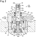
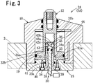
- the first clamp device 2A will be explained. Since, as shown in Figs. 2 and 3 , the first clamp device 2A principally comprises a hydraulic cylinder 5A, accordingly the following explanation will also include an explanation of this hydraulic cylinder 5A. While, in the case of this embodiment, the hydraulic cylinder 5A employs pressurized hydraulic fluid for its pressure fluid, it would also be acceptable to utilize an air cylinder that employs pressurized air, instead of pressurized hydraulic fluid. It should be understood that, in the following explanation, pressurized hydraulic fluid is sometimes referred to as pressurized oil.
- the first clamp device 2A comprises a cylinder main body 10, a cylinder bore 11 that is formed in the cylinder main body 10 in a vertical orientation, a piston member 12, and first and second hydraulic pressure operation chambers 13a, 13b.
- the cylinder main body 10 comprises an upper main body portion 10a and a lower main body portion 10b, with the lower main body portion 10b being fitted into a cylindrical holding hole 3a in the clamp installation member 3, an installation surface 10c at the lower end of the upper main body portion 10a being contacted against the upper surface of the clamp installation member 3, and the upper main body portion 10a being fixed to the clamp installation member 3 by a plurality of bolts (not shown in the figures).
- the lower main body portion 10b includes a cylindrical portion 14 and a plate shaped head side end wall member 15 that blocks the lower end of the cylinder bore 11, with a fitting portion 15a that is fitted into the lower end portion of the cylinder bore 11 being formed at the upper side portion of this head side end wall member 15, and the head side end wall member 15 being fixed to the lower end of the cylindrical portion 14 by a plurality of bolts (not shown in the figures).
- a seal member 15b is installed on the external periphery of a portion of the fitting portion 15a, near its lower end portion.
- the piston member 12 comprises a piston portion 12a that is installed in the cylinder bore 11 so as to be movable in its axial direction (i.e. so as to slide freely therein), and an output rod 12b that passes through a rod hole 17 formed in a rod side end wall 16 of the upper main body portion 10a and that extends upward from the piston portion 12a and projects to the exterior of the cylinder main body 10; and a threaded hole 12c is formed at the upper end portion of the output rod 12b so as to open to the upper end thereof, with a foot portion 18a of a pressing member 18 that presses on the workpiece W being screwed into and engaged with the threaded hole 12c, and a head portion 18b of the pressing member being exposed at the upper end of the output rod 12b.
- the upper surface of the head portion 18b of the pressing member 18 is shaped as a part spherical surface, or as a curved shape which is close to being a part spherical surface.
- a seal member 19 is installed on an external circumferential portion of the piston portion 12a, and a seal member 20 and a scraper 21 are installed in the inner peripheral portion of the rod hole 17. It should be understood that it would also be acceptable to make the piston member 12 with a plurality of members.
- the first hydraulic pressure operation chamber 13a is an operation chamber for clamping that is defined within the cylinder bore 11, between the piston portion 12a and the head side end wall member 15 (i.e. the head side end wall). It should be understood that the wall portion of the head side end wall member 15 that corresponds to the cylinder bore 11 is the "head side end wall”.
- the second hydraulic pressure operation chamber 13b is an operation chamber for unclamping that is defined within the cylinder bore 11, between the piston portion 12a and the rod side end wall 16.
- a first hydraulic conduit 22 for supplying pressurized hydraulic fluid to the first hydraulic pressure operation chamber 13a and discharging it therefrom and a second hydraulic conduit 23 for supplying pressurized hydraulic fluid to the second hydraulic pressure operation chamber 13b and discharging it therefrom are formed in the wall portion of the cylinder main body 10, and these first and second hydraulic conduits 22, 23 are connected to a hydraulic pressure supply source (not shown in the figures).
- the second hydraulic pressure operation chamber 13b can be omitted; it would also be acceptable to form a vent passage instead of the second hydraulic conduit 23, and, instead of the second hydraulic pressure operation chamber 13b, to install a compression spring that elastically biases the piston portion 12a downwards in a spring installation chamber.
- This operational state detection mechanism 30 comprises a rod insertion hole 31, an auxiliary rod member 33 that includes an auxiliary rod 32, a rod fitting hole 34, a movable rod 35, a movement restriction mechanism 36, a detection switch 37, and so on.
- the rod insertion hole 31 is formed in the piston portion 12a and a portion of the output rod 12b, so as to communicate with the first hydraulic pressure operation chamber 13a.
- the rod insertion hole 31 includes a large diameter hole 31a at its lower end portion and a small diameter hole 31b that is connected to the upper end of the large diameter hole 31a via a short tapered hole 31c.
- An auxiliary rod 32 is provided so as to project within the cylinder bore 11 on the head side end wall member 15 (i.e. the head side end wall), and moreover so as to be capable of being inserted into the rod insertion hole 31.
- an fitting hole forming wall portion 15c of the head side end wall member 15 that forms a portion of the rod fitting hole 34, and the auxiliary rod 32 are both constituted with a single integrally formed auxiliary rod member 33, and the auxiliary rod member 33 is detachably fixed to the cylinder main body 10, in order to make it possible to exchange of the auxiliary rod member 33 for another auxiliary rod member 33B whose length is different from that of this auxiliary rod member 33.
- the fitting hole forming wall portion 15c and the auxiliary rod 32 are formed to have equal external diameters, and the auxiliary rod 32 is formed over approximately the upper 2/3 portion of the auxiliary rod member 33.
- the upper end of the auxiliary rod 32 is positioned at an intermediate portion of the cylinder bore 11.
- a flange portion 33a is formed at the lower end portion of the auxiliary rod member 33, and a circular concave portion 38 into which the flange portion 33a is fitted and a vertically oriented communication hole 39, which can pass the auxiliary rod 32 and which communicates to the center portion of the circular concave portion 38, are formed in the head side end wall member 15.
- the flange portion 33a is fixed to the head side end wall member 15 by a plurality of bolts 40.
- a seal member 41 is installed to the internal circumferential portion of the communication hole 39.
- the auxiliary rod 32 projects from the upper surface of the head side end wall member 15 into the cylinder bore 11, and the auxiliary rod 32 can be inserted into the rod insertion hole 31.
- the flange portion 33a is not essential; it would also be acceptable to fix the auxiliary rod member 33 to the head side end wall member 15 with a fixing construction that is different from the fixing construction employing the flange portion 33a, described above.
- the rod fitting hole 34 is formed so as to penetrate the head side end wall member 15 and the auxiliary rod 32 in the axial direction.
- the lower end portion of the rod fitting hole 34 is formed in the fitting hole forming wall portion 15c, which is one portion of the head side end wall member 15.
- the movable rod 35 is installed in the rod fitting hole 34 so as to slide freely therein in the vertical direction, and moreover the end portion thereof on the side of the head side end wall member 15 projects to the exterior from the rod fitting hole 34.
- the movement restriction mechanism 36 prohibits shifting of the movable rod 35 in the axial direction in the state in which the lower end of the piston portion 12a is positioned at a first region within the cylinder bore 11, also, in the state in which the lower end of the piston portion 12a is positioned at a second region within the cylinder bore 11, the movement restriction mechanism 36 permits shifting of the movable rod 35 in the axial direction, so that, due to hydraulic pressure in the rod insertion hole 31, the movable rod 35 is caused to shift by a predetermined distance in the direction that increases an amount of projection by which it projects to the exterior from the rod fitting hole 34.
- the first region is the region a within the cylinder bore 11 shown in Fig.
- the piston portion 12a is positioned at an intermediate portion of the cylinder bore 11 in its lengthwise direction.
- the movement restriction mechanism 36 prohibits shifting of the movable rod 35 in the axial direction in the state in which the piston member 12 is in its unclamp position, also, in the state in which the piston member 12 is in its clamp position, the movement restriction mechanism 36 permits shifting of the movable rod 35 in the axial direction, so that, due to hydraulic pressure in the rod insertion hole 31, the movable rod 35 is caused to shift by a predetermined distance in the direction that increases the amount of projection by which it projects to the exterior from the rod installation hole 34. Due to the shape of the workpiece W that is fixed by the first and second clamp devices 2A, 2B, the first clamp device 2A goes into the clamped state in the state in which the piston portion 12a has shifted forward by about 1/2 of its full stroke. On the other hand, the second clamp device 2B goes into the clamped state in the state in which the piston member 21 has shifted forward to near its full stroke.
- the movement restriction mechanism 36 comprises: a large diameter portion 35a at the tip end portion of the movable rod 35 (i.e. at its upper end portion) that is formed to have a larger diameter than its other portion (i.e. a small diameter portion 35b); a seal member 42 that is installed over the external circumferential portion of the large diameter portion 35a; a large diameter hole portion 34a that is formed in a portion of the rod fitting hole 34 and that allows the large diameter portion 35a to be movable in the axial direction; an annular concave portion 43 that is formed around the external circumferential portion of the large diameter portion 35a of the movable rod 35; a plurality of ball holding openings 44 that are formed in the cylindrical circumferential wall 33b of the auxiliary rod 32 where its external peripheral surface fits into the large diameter hole portion 34a; a plurality of balls 45 (steel balls) that are received in the plurality of ball holding openings 44 so as to be individually movable in radial directions, and that are capable of being partially engaged with the annul
- the small diameter hole 31b is formed so that, when the lower end of the piston portion 12a is in the first region a, the plurality of balls 45 are partially engaged into the annular concave portion 43 (refer to Fig. 3 ).
- the large diameter hole 31a is formed so that, when the lower end of the piston portion 12a is in the second region b, the plurality of balls 45 are allowed to escape from the annular concave portion 43 (refer to Fig. 2 ).
- the short tapered hole 31c that extends along the axial direction is formed at the boundary portion between the small diameter hole 31b and the large diameter hole 31a.
- the half cross section of the annular concave portion 43 is an isosceles trapezoid: the annular concave portion 43 is defined by a small diameter cylindrical surface 43a, an upper part conical surface 43b that connects to the upper end of the cylindrical surface 43a, and a lower part conical surface 43c that connects to the lower end of the cylindrical surface 43a. Even when the plurality of balls 45 are contacted against the inner circumferential surface of the large diameter hole 31a, very small portions of the balls 45 are still projected into the annular concave portion 43.
- a detection switch 37 is provided that detects whether or not the movable rod 35 has shifted and outputs a detection signal; this detection switch 37 is built with a limit switch or a proximity switch or the like, and is attached to the outer surface of the head side end wall member 15.
- the detection signal of the detection switch 37 is set to go to ON, and the detection signal of the detection switch 37 is supplied to a control unit (not shown in the figures) that controls a hydraulic pressure supply source or the like.
- the second clamp device 2B shown in Fig. 4 (clamped state) includes a hydraulic cylinder 5B and fundamentally has a similar construction to that of the first clamp device 2A, but is built so as to go into the clamped state in the state in which the piston member 12 has shifted forward to near its full stroke; and, when the lower end of the piston portion 12a is in the second region, the piston portion 12a contacts against or is near to the rod side end wall 16. Due to this, the auxiliary rod 32B of the auxiliary rod member 33B is formed to be longer than the auxiliary rod 32 of the first clamp device 2A. To structural elements that are similar in structure to structural elements of the first clamp device 2A, the same reference numerals are appended, and description thereof is omitted.
- first and second clamp devices 2A, 2B operate in similar ways and provide similar advantageous effects, accordingly only the operation of the first clamp device 2A and its advantageous effects will be explained.
- the first clamp device 2A goes into its unclamped state shown in Fig. 3 . Since, in this state, the piston portion 12a of the piston member 12 is lowered down to its lower limit position, accordingly the plurality of balls 45 are positioned within the small diameter hole 31b and are engaged to the annular concave portion 43. Due to this, even though hydraulic pressure is acting on the upper end of the movable rod 35, the movable rod 35 is not shifted to project, and accordingly the detection signal of the detection switch 37 remains at OFF.
- the first clamp device 2A goes into the clamped state shown in Fig. 2 . Since, in this state, the piston portion 12a of the piston member 12 is positioned at an intermediate portion of the cylinder bore 11, the plurality of balls 45 are positioned within the large diameter hole 31a, and the hydraulic pressure within the rod insertion hole 31 acts on the upper end of the movable rod 35, accordingly the plurality of balls 45 are pressed by the upper part conical surface 43b of the annular concave portion 43 and move radially outward, so that they become in the state of being almost removed from the annular concave portion 43.
- the control unit understands that the first clamp device 2A has transitioned to its clamped state.
- the rod insertion hole 31, the auxiliary rod 32, the rod fitting hole 34, the movable rod 35, and the major portion of the movement restriction mechanism 36 can be provided within the hydraulic cylinder 5A, accordingly it is possible to prevent increase in size of the hydraulic cylinder 5A due to the provision of the above described movement restriction mechanism 36.
- the movement restriction mechanism 36 it is possible to set the first and second regions a, b freely via the small diameter hole 31b and the large diameter hole 31a, accordingly it is possible freely to set the position of the object of detection, i.e. the piston member 12.
- the movable rod 35 is shifted in the direction to increase its amount of projection at least by the hydraulic pressure in the single first hydraulic pressure operation chamber 13a between the piston portion 12a and the head side end wall member 15, accordingly this is appropriate for detection of the position of the piston member 12 when the piston member 12 has shifted by a predetermined amount in the direction to advance the output rod, or by the maximum limit amount.
- the movement restriction mechanism 36 comprises the large diameter portion 35a, the seal member 42, the large diameter hole portion 34a, the annular concave portion 43, the ball holding openings 44, the plurality of balls 45, and the small diameter hole 31b and the large diameter hole 31a that are formed in the rod insertion hole 31, accordingly, when the lower end of the piston portion 12a is in the first region a, the plurality of balls 45 are engaged to the annular concave portion 43 via the small diameter hole 31b, and the movable rod 35 is restrained so that it does not shift; and, when the lower end of the piston portion 12a is in the second region b, the plurality of balls 45 are almost removed out from the annular concave portion 34 via the large diameter hole 31a, and the movable rod 35 is shifted in the direction to increase its amount of projection due to the hydraulic pressure in the first hydraulic pressure operation chamber 13a.
- the movement restriction mechanism 36 has a simple structure and excellent durability, and its major portion can be formed within the hydraulic cylinder 5A.
- the fitting hole forming wall portion 15c that forms the rod fitting hole 34 and the auxiliary rod 32 are constituted by the single integral auxiliary rod member 33, and since the auxiliary rod member 33b is detachably fixed to the cylinder main body 10 in order to be possible to exchange of the auxiliary rod member 33 for an auxiliary rod member 33B whose length is different, accordingly, not only is it possible to change the first and second regions a, b by exchanging of the auxiliary rod member 33 for an auxiliary rod member 33B whose length is different, so that it is possible to change the position of the piston member 12 which is the oject for detection, but also it is possible to reduce the cost of production, as compared to the case when the auxiliary rod 32 is formed integrally with the head side end wall member 15 (i.e. with the head side end wall).
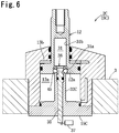
- the auxiliary rod 32C is formed integrally with the head side end wall member 15C, and the auxiliary rod 32C is formed so as to project within the cylinder bore 11; and, when the lower end of the piston portion 12a is in the second region as in Fig. 6 , the piston portion 12a contacts against or approaches the rod side end wall 16.
- the rod fitting hole 34C is formed so as to penetrate through the auxiliary rod 32C and through the head side end wall member 15C, parallel to the axis of the cylinder bore 11. Even when this auxiliary rod 32C is employed, it is still possible to exchange the auxiliary rod 32C by exchanging the head side end wall member 15C. Since almost similar operation and beneficial effects are obtained as those obtained with the first and second clamp devices 2A, 2B of the first embodiment, accordingly explanation thereof will be omitted.
- Embodiment #3 is formed integrally with the head side end wall member 15C, and the auxiliary rod 32C is formed so as to project within the cylinder bore 11; and, when the lower end of the piston portion 12a is in the second
- a clamp device 2D of a third embodiment and a hydraulic cylinder 5D that is included therein are fundamentally similar to the first embodiment, accordingly the same reference numerals are appended to structural elements that are the same as in the first embodiment and explanation thereof will be omitted, and principally only structures that are different from the first embodiment will be explained on the basis of Fig. 7 .
- the auxiliary rod member 33D that includes the auxiliary rod 32D is fixed to the head side end wall member 15D via a position adjustment mechanism 50. And a concave portion 51 whose lower end is open is formed in the head side end wall member 15D.
- the position adjustment mechanism 50 comprises: a male screw portion 52 that is formed on a portion of the external circumferential portion of the auxiliary rod member 33D; a threaded hole 53 that is formed in the center portion of the head side end wall member 15D so as to be oriented vertically, and into which the male screw portion 52 of the auxiliary rod member 33D is screwed and is engaged; a lock nut 54 that is screwed over and engaged with the male screw portion at the exterior of the threaded hole 53; and a seal washer 55 that is fitted over the exterior of the auxiliary rod member 3D, between the head side end wall 15d and the lock nut 54.
- the male screw portion 52 is formed on the entire external circumferential portion of the auxiliary rod member 33D, with the exception of its upper end portion. It will be supposed that, during assembly of the clamp device 2D, the head side end wall member 15D is fixed to the cylindrical portion 14 of the lower main body portion 10b after the auxiliary rod member 33D is attached to the head side end wall member 15D.
- Fig. 7 shows the state when the clamp device 2D is in the clamped state
- the piston portion 12a is positioned partway along the cylinder bore 11 (i.e. at an intermediate portion) when the clamp device 2D reaches its clamped state
- almost similar operation and beneficial effects are obtained as those obtained with the first and second clamp devices 2A, 2B of the first embodiment.
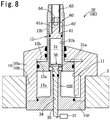
- a clamp device 2E of a fourth embodiment and a hydraulic cylinder 5E that is included therein are fundamentally similar to the first embodiment, accordingly the same reference numerals are appended to structural elements that are the same as in the first embodiment and explanation thereof will be omitted, and principally only structures that are different from the first embodiment will be explained on the basis of Fig. 8 .
- an auxiliary rod 32E is formed integrally with the head side end wall member 15E, and projects into the cylinder bore 11.
- This clamp device 2E has a large diameter hole length adjustment mechanism 60 that is capable of adjusting the length of the large diameter hole 31a, and this large diameter hole length adjustment mechanism 60 comprises a small diameter hole forming member 61 that forms a small diameter hole 31b in the piston member 12, a sliding hole 62 that is formed in the piston member 12 and in which the small diameter hole definition member 61 is installed so as to slide freely in the axial direction and that is of the same diameter as the large diameter hole 31a, a threaded hole 63 that is formed in the output rod 12b further toward its end than the sliding hole 62, a screw shaft 61a that is formed integrally with the small diameter hole forming member 61 and that is screwed into and engaged with the threaded hole 63, and a tool engagement hole 64 that is formed at the tip end portion of the screw shaft 61a; and, with this structure, it is possible to adjust the position of the small diameter hole forming member 61 with respect to the piston member 12 through a predetermined distance in the vertical direction.
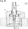
- a clamp device 2F of a fifth embodiment and a hydraulic cylinder 5F that is included therein are fundamentally similar to the first embodiment, accordingly the same reference numerals are appended to structural elements that are the same as in the first embodiment and explanation thereof will be omitted, and principally only structures that are different from the first embodiment will be explained on the basis of Figs. 9 and 10 .
- an auxiliary rod 32F is formed integrally with the head side end wall member 15F, and projects to within the cylinder bore 11.
- This clamp device 2F has a hydraulic pressure responsive mechanism 70 that is responsive to the hydraulic pressure within the first hydraulic pressure operation chamber 13a, and this hydraulic pressure responsive mechanism 70 comprises a spring installation hole 71 that is formed in the auxiliary rod 32F so as to communicate with the large diameter hole portion 34a and a compression coil spring 72 that biases a movable rod 35 that is installed in a portion of the large diameter hole portion 34a and in the spring installation hole 71 toward the inner end (i.e. the upper end) of the rod insertion hole 31.
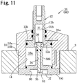
- a clamp device 2G of a sixth embodiment and a hydraulic cylinder 5G that is included therein are fundamentally similar to the first embodiment, accordingly the same reference numerals are appended to structural elements that are the same as in the first embodiment and explanation thereof will be omitted, and principally only structures that are different from the first embodiment will be explained on the basis of Fig. 11 .
- an auxiliary rod 32G is formed integrally with the head side end wall member 15G, and projects to within the cylinder bore 11.
- the thickness of the head side end wall member 15G is made to be great, and a switch reception concave portion 80 having its lower end open is formed in the lower portion of the central portion of the head side end wall member 15G, with a detection switch 37 being received in the switch reception concave portion 80 and being fixed to a wall portion of the switch reception concave portion 80, and with the lower end portion of the movable rod 35 projecting into the switch reception concave portion 80.
- the amount of projection of the lower end portion of the movable rod 35 increases and the detection switch 37 goes into the actuated state.
- the lower end of the switch reception concave portion 80 may be covered over with a lid plate 81 made from metal.
- a lid plate 81 made from metal.
Landscapes
- Engineering & Computer Science (AREA)
- Mechanical Engineering (AREA)
- Physics & Mathematics (AREA)
- Fluid Mechanics (AREA)
- General Engineering & Computer Science (AREA)
- Actuator (AREA)
- Jigs For Machine Tools (AREA)
Applications Claiming Priority (2)
| Application Number | Priority Date | Filing Date | Title |
|---|---|---|---|
| JP2014115724A JP6410342B2 (ja) | 2014-06-04 | 2014-06-04 | 流体圧シリンダ及びクランプ装置 |
| PCT/JP2015/061226 WO2015186432A1 (ja) | 2014-06-04 | 2015-04-10 | 流体圧シリンダ及びクランプ装置 |
Publications (3)
| Publication Number | Publication Date |
|---|---|
| EP3153712A1 EP3153712A1 (en) | 2017-04-12 |
| EP3153712A4 EP3153712A4 (en) | 2018-02-07 |
| EP3153712B1 true EP3153712B1 (en) | 2019-06-19 |
Family
ID=54766512
Family Applications (1)
| Application Number | Title | Priority Date | Filing Date |
|---|---|---|---|
| EP15803701.0A Active EP3153712B1 (en) | 2014-06-04 | 2015-04-10 | Hydraulic cylinder and clamp device |
Country Status (7)
| Country | Link |
|---|---|
| US (1) | US10316870B2 (zh) |
| EP (1) | EP3153712B1 (zh) |
| JP (1) | JP6410342B2 (zh) |
| KR (1) | KR20170013874A (zh) |
| CN (1) | CN106232999B (zh) |
| TW (1) | TWI647388B (zh) |
| WO (1) | WO2015186432A1 (zh) |
Families Citing this family (7)
| Publication number | Priority date | Publication date | Assignee | Title |
|---|---|---|---|---|
| JP6641358B2 (ja) * | 2015-04-13 | 2020-02-05 | 株式会社コスメック | シリンダ装置 |
| CN107971968B (zh) * | 2017-12-28 | 2024-04-05 | 江西腾勒动力有限公司 | 一种发动机液压挺柱安装工装 |
| CN108953288A (zh) * | 2018-09-30 | 2018-12-07 | 中国船舶重工集团公司第七〇九研究所 | 用于双作用多级液压缸的顶杆装置 |
| JP7193122B2 (ja) * | 2018-10-22 | 2022-12-20 | 株式会社コスメック | ワークサポート |
| CN112179640A (zh) * | 2020-09-30 | 2021-01-05 | 湖南常德牌水表制造有限公司 | 一种水表壳耐压检测装置 |
| CN112405349A (zh) * | 2020-11-30 | 2021-02-26 | 北京第二机床厂有限公司 | 回转气缸前置式磨床自动卡具 |
| CN115179217B (zh) * | 2022-08-17 | 2024-02-23 | 成都成林数控刀具股份有限公司 | 一种液压夹具 |
Family Cites Families (32)
| Publication number | Priority date | Publication date | Assignee | Title |
|---|---|---|---|---|
| US3340371A (en) * | 1965-10-23 | 1967-09-05 | Lea G Trimmer | Switch device for pressure cylinders |
| JPS4714028Y1 (zh) * | 1966-11-09 | 1972-05-22 | ||
| US3661053A (en) * | 1970-12-04 | 1972-05-09 | Parker Hannifin Corp | Reversing switch actuator for fluid motor |
| JPS52154976A (en) * | 1976-06-18 | 1977-12-23 | Teijin Seiki Co Ltd | Actuator |
| JPS5918165Y2 (ja) | 1978-12-08 | 1984-05-26 | 株式会社小松製作所 | シリンダのストロ−ク端検出装置 |
| JPS5584301A (en) | 1978-12-21 | 1980-06-25 | Mitsubishi Chem Ind Ltd | Preparation of hydrocarbon polymer derivative |
| DE3438185A1 (de) * | 1984-10-18 | 1986-04-24 | Johann Weiss Maschinenbau, 7799 Illmensee | Druckmittelbetaetigter spannzylinder mit sicherheitsabschaltung |
| IT1177258B (it) * | 1984-11-19 | 1987-08-26 | Alfa Romeo Auto Spa | Attuatore autobloccante, a fluido |
| DE3605620A1 (de) * | 1985-10-19 | 1987-08-27 | Optima Spanntechnik Gmbh | Spannvorrichtung |
| US5171001A (en) * | 1987-05-27 | 1992-12-15 | Btm Corporation | Sealed power clamp |
| US5118088A (en) * | 1990-04-30 | 1992-06-02 | Btm Corporation | Power clamp |
| US5190272A (en) * | 1990-12-20 | 1993-03-02 | Snow/Taft-Peirce Company | Actuator and palletizing system |
| JPH1130201A (ja) * | 1997-05-16 | 1999-02-02 | Nok Corp | ピストン型アキュムレータのピストン位置検出装置 |
| JP3954704B2 (ja) * | 1997-10-31 | 2007-08-08 | 株式会社コスメック | クランプ装置 |
| TW379155B (en) * | 1997-10-31 | 2000-01-11 | Kosmek Kk | Transmission apparatus |
| JP3550010B2 (ja) * | 1997-12-24 | 2004-08-04 | 株式会社コスメック | クランプ装置 |
| JP2001087991A (ja) * | 1999-09-24 | 2001-04-03 | Taiyo Ltd | クランプの確認制御方法および装置 |
| US6502880B1 (en) * | 2000-03-08 | 2003-01-07 | Btm Corporation | Pin part locator |
| TW579316B (en) * | 2001-11-13 | 2004-03-11 | Kosmek Ltd | Rotary clamp |
| JP3881589B2 (ja) * | 2002-02-13 | 2007-02-14 | 株式会社コスメック | シリンダ装置 |
| ATE297286T1 (de) * | 2002-09-09 | 2005-06-15 | Hermle Berthold Maschf Ag | Festspanneinrichtung zum festspannen zweier teile aneinander |
| US7971883B2 (en) * | 2005-09-07 | 2011-07-05 | Hardinge, Inc. | Workholding clamping assembly |
| WO2007043183A1 (ja) * | 2005-10-14 | 2007-04-19 | Pascal Engineering Corporation | スイング式クランプ装置 |
| WO2010140554A1 (ja) * | 2009-06-02 | 2010-12-09 | 株式会社コスメック | クランプ装置 |
| JP5557630B2 (ja) * | 2010-07-13 | 2014-07-23 | パスカルエンジニアリング株式会社 | クランプ装置 |
| JP2012166276A (ja) * | 2011-02-10 | 2012-09-06 | Pascal Engineering Corp | クランプ装置のロッド位置検出装置 |
| JP5841152B2 (ja) * | 2011-08-08 | 2016-01-13 | 株式会社コスメック | アクチュエータ及びそれを用いたクランプ装置 |
| JP5129378B1 (ja) * | 2011-08-26 | 2013-01-30 | 株式会社コスメック | 倍力機構付きシリンダ装置 |
| JP5337221B2 (ja) * | 2011-10-07 | 2013-11-06 | パスカルエンジニアリング株式会社 | 流体圧シリンダ及びクランプ装置 |
| CN104395616B (zh) * | 2012-07-20 | 2016-08-17 | 博格华纳公司 | 内部位置传感器 |
| JP6012445B2 (ja) * | 2012-11-13 | 2016-10-25 | パスカルエンジニアリング株式会社 | 流体圧シリンダ及び旋回式クランプ装置 |
| CN203560197U (zh) * | 2013-09-18 | 2014-04-23 | 毕晴春 | 一种浮动支承油缸 |
-
2014
- 2014-06-04 JP JP2014115724A patent/JP6410342B2/ja active Active
-
2015
- 2015-04-10 EP EP15803701.0A patent/EP3153712B1/en active Active
- 2015-04-10 KR KR1020167033006A patent/KR20170013874A/ko unknown
- 2015-04-10 CN CN201580021518.6A patent/CN106232999B/zh active Active
- 2015-04-10 US US15/315,600 patent/US10316870B2/en active Active
- 2015-04-10 WO PCT/JP2015/061226 patent/WO2015186432A1/ja active Application Filing
- 2015-04-16 TW TW104112233A patent/TWI647388B/zh active
Non-Patent Citations (1)
| Title |
|---|
| None * |
Also Published As
| Publication number | Publication date |
|---|---|
| US20170198729A1 (en) | 2017-07-13 |
| WO2015186432A1 (ja) | 2015-12-10 |
| JP2015230025A (ja) | 2015-12-21 |
| US10316870B2 (en) | 2019-06-11 |
| EP3153712A4 (en) | 2018-02-07 |
| KR20170013874A (ko) | 2017-02-07 |
| CN106232999B (zh) | 2018-06-01 |
| CN106232999A (zh) | 2016-12-14 |
| JP6410342B2 (ja) | 2018-10-24 |
| EP3153712A1 (en) | 2017-04-12 |
| TW201546375A (zh) | 2015-12-16 |
| TWI647388B (zh) | 2019-01-11 |
Similar Documents
| Publication | Publication Date | Title |
|---|---|---|
| EP3153712B1 (en) | Hydraulic cylinder and clamp device | |
| US20140138890A1 (en) | Fluid pressure cylinder and clamp device | |
| EP2929980B1 (en) | Fluid pressure cylinder | |
| EP3127653B1 (en) | Clamp apparatus | |
| US20130113146A1 (en) | Clamp device | |
| US9061385B2 (en) | Clamp device | |
| US9353861B2 (en) | Coupling structure for piston used in fluid-pressure cylinder, and coupling method therefor | |
| US9823142B2 (en) | Force sensor for manually operated or pneumatic presses | |
| CN202348818U (zh) | 一种带有接近开关的油缸 | |
| EP2676766B1 (en) | Positioning device | |
| JP2015230025A5 (zh) | ||
| US8696206B2 (en) | Bearing ring comprising a hydraulic preloading means and bearing assembly comprising such a bearing ring | |
| EP2233245B1 (en) | Clamping device | |
| CN104358731A (zh) | 一种用于液压夹具上锁定用液压缸 | |
| JP6285655B2 (ja) | クランプ装置 | |
| CN107208669B (zh) | 流体压力缸 | |
| KR20150141998A (ko) | 위치결정 장치 | |
| WO2011037091A1 (ja) | ネジ係合式クランプ装置及びクランピングシステム並びに流体圧アクチュエータ | |
| JP2006329803A (ja) | 高圧車室の水圧試験構造及び水圧試験方法 | |
| CN109667928B (zh) | 用于致动变速器的选择器杆的设定装置 | |
| CN203223434U (zh) | 具有机械锁止装置的行程调整机构 | |
| CN108626211B (zh) | 一种光轴锁紧机构及操作方法 | |
| JP6954750B2 (ja) | クランプ装置 | |
| JP7201475B2 (ja) | クランプ装置 | |
| CN108302127B (zh) | 具有自动张紧功能的轴 |
Legal Events
| Date | Code | Title | Description |
|---|---|---|---|
| STAA | Information on the status of an ep patent application or granted ep patent |
Free format text: STATUS: THE INTERNATIONAL PUBLICATION HAS BEEN MADE |
|
| PUAI | Public reference made under article 153(3) epc to a published international application that has entered the european phase |
Free format text: ORIGINAL CODE: 0009012 |
|
| STAA | Information on the status of an ep patent application or granted ep patent |
Free format text: STATUS: REQUEST FOR EXAMINATION WAS MADE |
|
| 17P | Request for examination filed |
Effective date: 20161121 |
|
| AK | Designated contracting states |
Kind code of ref document: A1 Designated state(s): AL AT BE BG CH CY CZ DE DK EE ES FI FR GB GR HR HU IE IS IT LI LT LU LV MC MK MT NL NO PL PT RO RS SE SI SK SM TR |
|
| AX | Request for extension of the european patent |
Extension state: BA ME |
|
| DAV | Request for validation of the european patent (deleted) | ||
| DAX | Request for extension of the european patent (deleted) | ||
| A4 | Supplementary search report drawn up and despatched |
Effective date: 20180109 |
|
| RIC1 | Information provided on ipc code assigned before grant |
Ipc: B23Q 3/06 20060101ALI20180103BHEP Ipc: F15B 15/28 20060101AFI20180103BHEP Ipc: B25B 5/06 20060101ALI20180103BHEP Ipc: F15B 15/14 20060101ALI20180103BHEP Ipc: B23Q 3/08 20060101ALI20180103BHEP |
|
| GRAP | Despatch of communication of intention to grant a patent |
Free format text: ORIGINAL CODE: EPIDOSNIGR1 |
|
| STAA | Information on the status of an ep patent application or granted ep patent |
Free format text: STATUS: GRANT OF PATENT IS INTENDED |
|
| INTG | Intention to grant announced |
Effective date: 20190118 |
|
| GRAJ | Information related to disapproval of communication of intention to grant by the applicant or resumption of examination proceedings by the epo deleted |
Free format text: ORIGINAL CODE: EPIDOSDIGR1 |
|
| STAA | Information on the status of an ep patent application or granted ep patent |
Free format text: STATUS: REQUEST FOR EXAMINATION WAS MADE |
|
| GRAR | Information related to intention to grant a patent recorded |
Free format text: ORIGINAL CODE: EPIDOSNIGR71 |
|
| GRAS | Grant fee paid |
Free format text: ORIGINAL CODE: EPIDOSNIGR3 |
|
| STAA | Information on the status of an ep patent application or granted ep patent |
Free format text: STATUS: GRANT OF PATENT IS INTENDED |
|
| GRAA | (expected) grant |
Free format text: ORIGINAL CODE: 0009210 |
|
| STAA | Information on the status of an ep patent application or granted ep patent |
Free format text: STATUS: THE PATENT HAS BEEN GRANTED |
|
| INTC | Intention to grant announced (deleted) | ||
| INTG | Intention to grant announced |
Effective date: 20190508 |
|
| AK | Designated contracting states |
Kind code of ref document: B1 Designated state(s): AL AT BE BG CH CY CZ DE DK EE ES FI FR GB GR HR HU IE IS IT LI LT LU LV MC MK MT NL NO PL PT RO RS SE SI SK SM TR |
|
| REG | Reference to a national code |
Ref country code: GB Ref legal event code: FG4D |
|
| REG | Reference to a national code |
Ref country code: CH Ref legal event code: EP |
|
| REG | Reference to a national code |
Ref country code: IE Ref legal event code: FG4D |
|
| REG | Reference to a national code |
Ref country code: AT Ref legal event code: REF Ref document number: 1145884 Country of ref document: AT Kind code of ref document: T Effective date: 20190715 |
|
| REG | Reference to a national code |
Ref country code: DE Ref legal event code: R096 Ref document number: 602015032378 Country of ref document: DE |
|
| REG | Reference to a national code |
Ref country code: NL Ref legal event code: MP Effective date: 20190619 |
|
| PG25 | Lapsed in a contracting state [announced via postgrant information from national office to epo] |
Ref country code: SE Free format text: LAPSE BECAUSE OF FAILURE TO SUBMIT A TRANSLATION OF THE DESCRIPTION OR TO PAY THE FEE WITHIN THE PRESCRIBED TIME-LIMIT Effective date: 20190619 Ref country code: AL Free format text: LAPSE BECAUSE OF FAILURE TO SUBMIT A TRANSLATION OF THE DESCRIPTION OR TO PAY THE FEE WITHIN THE PRESCRIBED TIME-LIMIT Effective date: 20190619 Ref country code: FI Free format text: LAPSE BECAUSE OF FAILURE TO SUBMIT A TRANSLATION OF THE DESCRIPTION OR TO PAY THE FEE WITHIN THE PRESCRIBED TIME-LIMIT Effective date: 20190619 Ref country code: NO Free format text: LAPSE BECAUSE OF FAILURE TO SUBMIT A TRANSLATION OF THE DESCRIPTION OR TO PAY THE FEE WITHIN THE PRESCRIBED TIME-LIMIT Effective date: 20190919 Ref country code: HR Free format text: LAPSE BECAUSE OF FAILURE TO SUBMIT A TRANSLATION OF THE DESCRIPTION OR TO PAY THE FEE WITHIN THE PRESCRIBED TIME-LIMIT Effective date: 20190619 Ref country code: LT Free format text: LAPSE BECAUSE OF FAILURE TO SUBMIT A TRANSLATION OF THE DESCRIPTION OR TO PAY THE FEE WITHIN THE PRESCRIBED TIME-LIMIT Effective date: 20190619 |
|
| REG | Reference to a national code |
Ref country code: LT Ref legal event code: MG4D |
|
| PG25 | Lapsed in a contracting state [announced via postgrant information from national office to epo] |
Ref country code: RS Free format text: LAPSE BECAUSE OF FAILURE TO SUBMIT A TRANSLATION OF THE DESCRIPTION OR TO PAY THE FEE WITHIN THE PRESCRIBED TIME-LIMIT Effective date: 20190619 Ref country code: GR Free format text: LAPSE BECAUSE OF FAILURE TO SUBMIT A TRANSLATION OF THE DESCRIPTION OR TO PAY THE FEE WITHIN THE PRESCRIBED TIME-LIMIT Effective date: 20190920 Ref country code: LV Free format text: LAPSE BECAUSE OF FAILURE TO SUBMIT A TRANSLATION OF THE DESCRIPTION OR TO PAY THE FEE WITHIN THE PRESCRIBED TIME-LIMIT Effective date: 20190619 Ref country code: BG Free format text: LAPSE BECAUSE OF FAILURE TO SUBMIT A TRANSLATION OF THE DESCRIPTION OR TO PAY THE FEE WITHIN THE PRESCRIBED TIME-LIMIT Effective date: 20190919 |
|
| REG | Reference to a national code |
Ref country code: AT Ref legal event code: MK05 Ref document number: 1145884 Country of ref document: AT Kind code of ref document: T Effective date: 20190619 |
|
| PG25 | Lapsed in a contracting state [announced via postgrant information from national office to epo] |
Ref country code: AT Free format text: LAPSE BECAUSE OF FAILURE TO SUBMIT A TRANSLATION OF THE DESCRIPTION OR TO PAY THE FEE WITHIN THE PRESCRIBED TIME-LIMIT Effective date: 20190619 Ref country code: NL Free format text: LAPSE BECAUSE OF FAILURE TO SUBMIT A TRANSLATION OF THE DESCRIPTION OR TO PAY THE FEE WITHIN THE PRESCRIBED TIME-LIMIT Effective date: 20190619 Ref country code: PT Free format text: LAPSE BECAUSE OF FAILURE TO SUBMIT A TRANSLATION OF THE DESCRIPTION OR TO PAY THE FEE WITHIN THE PRESCRIBED TIME-LIMIT Effective date: 20191021 Ref country code: EE Free format text: LAPSE BECAUSE OF FAILURE TO SUBMIT A TRANSLATION OF THE DESCRIPTION OR TO PAY THE FEE WITHIN THE PRESCRIBED TIME-LIMIT Effective date: 20190619 Ref country code: RO Free format text: LAPSE BECAUSE OF FAILURE TO SUBMIT A TRANSLATION OF THE DESCRIPTION OR TO PAY THE FEE WITHIN THE PRESCRIBED TIME-LIMIT Effective date: 20190619 Ref country code: CZ Free format text: LAPSE BECAUSE OF FAILURE TO SUBMIT A TRANSLATION OF THE DESCRIPTION OR TO PAY THE FEE WITHIN THE PRESCRIBED TIME-LIMIT Effective date: 20190619 Ref country code: SK Free format text: LAPSE BECAUSE OF FAILURE TO SUBMIT A TRANSLATION OF THE DESCRIPTION OR TO PAY THE FEE WITHIN THE PRESCRIBED TIME-LIMIT Effective date: 20190619 |
|
| PG25 | Lapsed in a contracting state [announced via postgrant information from national office to epo] |
Ref country code: SM Free format text: LAPSE BECAUSE OF FAILURE TO SUBMIT A TRANSLATION OF THE DESCRIPTION OR TO PAY THE FEE WITHIN THE PRESCRIBED TIME-LIMIT Effective date: 20190619 Ref country code: IS Free format text: LAPSE BECAUSE OF FAILURE TO SUBMIT A TRANSLATION OF THE DESCRIPTION OR TO PAY THE FEE WITHIN THE PRESCRIBED TIME-LIMIT Effective date: 20191019 Ref country code: ES Free format text: LAPSE BECAUSE OF FAILURE TO SUBMIT A TRANSLATION OF THE DESCRIPTION OR TO PAY THE FEE WITHIN THE PRESCRIBED TIME-LIMIT Effective date: 20190619 |
|
| PG25 | Lapsed in a contracting state [announced via postgrant information from national office to epo] |
Ref country code: TR Free format text: LAPSE BECAUSE OF FAILURE TO SUBMIT A TRANSLATION OF THE DESCRIPTION OR TO PAY THE FEE WITHIN THE PRESCRIBED TIME-LIMIT Effective date: 20190619 |
|
| PG25 | Lapsed in a contracting state [announced via postgrant information from national office to epo] |
Ref country code: DK Free format text: LAPSE BECAUSE OF FAILURE TO SUBMIT A TRANSLATION OF THE DESCRIPTION OR TO PAY THE FEE WITHIN THE PRESCRIBED TIME-LIMIT Effective date: 20190619 Ref country code: PL Free format text: LAPSE BECAUSE OF FAILURE TO SUBMIT A TRANSLATION OF THE DESCRIPTION OR TO PAY THE FEE WITHIN THE PRESCRIBED TIME-LIMIT Effective date: 20190619 |
|
| PG25 | Lapsed in a contracting state [announced via postgrant information from national office to epo] |
Ref country code: IS Free format text: LAPSE BECAUSE OF FAILURE TO SUBMIT A TRANSLATION OF THE DESCRIPTION OR TO PAY THE FEE WITHIN THE PRESCRIBED TIME-LIMIT Effective date: 20200224 |
|
| REG | Reference to a national code |
Ref country code: DE Ref legal event code: R097 Ref document number: 602015032378 Country of ref document: DE |
|
| PLBE | No opposition filed within time limit |
Free format text: ORIGINAL CODE: 0009261 |
|
| STAA | Information on the status of an ep patent application or granted ep patent |
Free format text: STATUS: NO OPPOSITION FILED WITHIN TIME LIMIT |
|
| PG2D | Information on lapse in contracting state deleted |
Ref country code: IS |
|
| 26N | No opposition filed |
Effective date: 20200603 |
|
| PG25 | Lapsed in a contracting state [announced via postgrant information from national office to epo] |
Ref country code: SI Free format text: LAPSE BECAUSE OF FAILURE TO SUBMIT A TRANSLATION OF THE DESCRIPTION OR TO PAY THE FEE WITHIN THE PRESCRIBED TIME-LIMIT Effective date: 20190619 |
|
| PG25 | Lapsed in a contracting state [announced via postgrant information from national office to epo] |
Ref country code: MC Free format text: LAPSE BECAUSE OF FAILURE TO SUBMIT A TRANSLATION OF THE DESCRIPTION OR TO PAY THE FEE WITHIN THE PRESCRIBED TIME-LIMIT Effective date: 20190619 |
|
| REG | Reference to a national code |
Ref country code: CH Ref legal event code: PL |
|
| PG25 | Lapsed in a contracting state [announced via postgrant information from national office to epo] |
Ref country code: CH Free format text: LAPSE BECAUSE OF NON-PAYMENT OF DUE FEES Effective date: 20200430 Ref country code: LU Free format text: LAPSE BECAUSE OF NON-PAYMENT OF DUE FEES Effective date: 20200410 Ref country code: LI Free format text: LAPSE BECAUSE OF NON-PAYMENT OF DUE FEES Effective date: 20200430 Ref country code: FR Free format text: LAPSE BECAUSE OF NON-PAYMENT OF DUE FEES Effective date: 20200430 |
|
| REG | Reference to a national code |
Ref country code: BE Ref legal event code: MM Effective date: 20200430 |
|
| PG25 | Lapsed in a contracting state [announced via postgrant information from national office to epo] |
Ref country code: BE Free format text: LAPSE BECAUSE OF NON-PAYMENT OF DUE FEES Effective date: 20200430 |
|
| GBPC | Gb: european patent ceased through non-payment of renewal fee |
Effective date: 20200410 |
|
| PG25 | Lapsed in a contracting state [announced via postgrant information from national office to epo] |
Ref country code: GB Free format text: LAPSE BECAUSE OF NON-PAYMENT OF DUE FEES Effective date: 20200410 Ref country code: IE Free format text: LAPSE BECAUSE OF NON-PAYMENT OF DUE FEES Effective date: 20200410 |
|
| PG25 | Lapsed in a contracting state [announced via postgrant information from national office to epo] |
Ref country code: MT Free format text: LAPSE BECAUSE OF FAILURE TO SUBMIT A TRANSLATION OF THE DESCRIPTION OR TO PAY THE FEE WITHIN THE PRESCRIBED TIME-LIMIT Effective date: 20190619 Ref country code: CY Free format text: LAPSE BECAUSE OF FAILURE TO SUBMIT A TRANSLATION OF THE DESCRIPTION OR TO PAY THE FEE WITHIN THE PRESCRIBED TIME-LIMIT Effective date: 20190619 |
|
| PG25 | Lapsed in a contracting state [announced via postgrant information from national office to epo] |
Ref country code: MK Free format text: LAPSE BECAUSE OF FAILURE TO SUBMIT A TRANSLATION OF THE DESCRIPTION OR TO PAY THE FEE WITHIN THE PRESCRIBED TIME-LIMIT Effective date: 20190619 |
|
| PGFP | Annual fee paid to national office [announced via postgrant information from national office to epo] |
Ref country code: IT Payment date: 20230310 Year of fee payment: 9 |
|
| PGFP | Annual fee paid to national office [announced via postgrant information from national office to epo] |
Ref country code: DE Payment date: 20230307 Year of fee payment: 9 |