EP3147407B1 - Scissors-type retractable structure - Google Patents
Scissors-type retractable structure Download PDFInfo
- Publication number
- EP3147407B1 EP3147407B1 EP14895015.7A EP14895015A EP3147407B1 EP 3147407 B1 EP3147407 B1 EP 3147407B1 EP 14895015 A EP14895015 A EP 14895015A EP 3147407 B1 EP3147407 B1 EP 3147407B1
- Authority
- EP
- European Patent Office
- Prior art keywords
- scissors
- frame
- bridge
- retractable bridge
- retractable
- Prior art date
- Legal status (The legal status is an assumption and is not a legal conclusion. Google has not performed a legal analysis and makes no representation as to the accuracy of the status listed.)
- Active
Links
Images


Classifications
-
- E—FIXED CONSTRUCTIONS
- E01—CONSTRUCTION OF ROADS, RAILWAYS, OR BRIDGES
- E01D—CONSTRUCTION OF BRIDGES, ELEVATED ROADWAYS OR VIADUCTS; ASSEMBLY OF BRIDGES
- E01D15/00—Movable or portable bridges; Floating bridges
- E01D15/12—Portable or sectional bridges
- E01D15/124—Folding or telescopic bridges; Bridges built up from folding or telescopic sections
-
- E—FIXED CONSTRUCTIONS
- E01—CONSTRUCTION OF ROADS, RAILWAYS, OR BRIDGES
- E01D—CONSTRUCTION OF BRIDGES, ELEVATED ROADWAYS OR VIADUCTS; ASSEMBLY OF BRIDGES
- E01D15/00—Movable or portable bridges; Floating bridges
- E01D15/14—Floating bridges, e.g. pontoon bridges
Definitions
- the present invention relates to a scissors-type retractable structure including a scissors structure.
- a temporary bridge of known art is provided to allow passage of private construction vehicles. Construction of such a temporary bridge is achieved by transporting parts of a temporary girder bridge or a truss bridge made of heavy steel, and assembling these parts according to a method suitable for the spot. Construction methods such as the cantilever method, the bent support method, and the incremental launching method are commonly used to construct structures not only in such a spot struck by a disaster but also in other places. The construction according to these methods takes at least several days.
- an expandable scissors link for shear reinforcement is known from, for example, Patent Document 1.
- This scissors link is configured to occupy a small space when it is transported or stored, and to be extended to achieve desired structure and length when it is used.
- Patent Document 1 Japanese Unexamined Patent Publication No. H11-210161 .
- GB 1 068 155 , GB 2 161 573 and WO 2010/127894 disclose scissors-type retractable structures.
- a scissors mechanism as described in Patent Document 1 has been difficult to apply to a large structure such as a bridge. This may be because, for example: the scissors mechanism provides few advantages when used as a bridge; it includes a controller, which increases the cost; if no control member is incorporated, it may come to be an instable structure; and while having a high stiffness in one direction, it tends to have a low stiffness in another direction. Further, stress concentration and wear which may occur due to the presence of hinges (pivots) at intersection points of parts make it difficult for the bridge design to ensure structural strength.
- deck plates may be provided to stabilize the scissors mechanism in an extended state, and to allow automobiles and other vehicles to pass across the mechanism.
- provision of the deck plates results in an increase in the number of parts. Further, for folding the scissors mechanism again, it requires huge force to erect the deck plates laying horizontally by applying the force in the horizontal direction. Furthermore, the increase in the number of the parts by the number of the deck plates complicates the configuration and the mechanism.
- the scissors-type retractable structure of the present invention is configured to form a substantially flat surface when the retractable structure is in a fully extended state, without using deck plates.
- a first aspect of the present invention relates to a scissors-type retractable bridge which is extendable in an extension direction.
- the scissors-type retractable bridge includes: at least one scissors frame including a plurality of frame elements each consisting of two frame members pin-connected to each other at central portions of the frame members, the plurality of frame elements pin-connected to each other at end portions of the frame members, each frame member including a frame body having a pin-insertion central hole formed in a central portion of the frame body, and a deck member provided on an upper side of the frame body.
- part of the frame members forming the frame elements and positioned on a near side in the width direction of the retractable bridge are linearly coupled to each other, and the other part of the frame members forming the frame elements and positioned on a far side in the width direction of the retractable bridge are linearly coupled to each other, thereby causing upper surfaces of the frame members to form a continuous flat surface, the deck members being configured to form part of the flat surface, whereby the frame member functions as a scissors structure and as a deck plate structure as well, so that stabilization is achieved without using separate deck plate members.
- the upper surfaces of the frame members form a flat surface. Therefore, stabilization is achieved without using separate deck plate members, and the upper surfaces of the frame members function as deck plates to allow pedestrians and vehicles to pass over the frame members. Thanks to the absence of deck plate members, unlike a structure including deck plate members, it does not need huge force to erect the scissors-type retractable structure of the present invention being in its horizontal position and to bring the retractable structure into a standby state. The absence of deck plate members may result in a decrease in the number of parts, simplification of the configuration, and weight reduction.
- flat surface refers to not only a completely flat surface, but also a surface which is uneven to the extent that pedestrians and vehicles are allowed to pass.
- a plate-like member may be placed on, and integrally and firmly secured to, the upper surfaces of the frame members in an extended state, with bolts or other fasteners.
- a second aspect of the present invention is an embodiment of the scissors-type retractable bridge according to the first aspect, in which the at least one scissors frame includes a plurality of scissors frames arranged side by side toward the far side, and the plurality of scissors frames in the extended state form a girder.
- the width of the girder may be increased by arranging the plurality of scissors frames side by side toward the far side.
- a fourth aspect of the present invention is an embodiment of the scissors-type retractable bridge according to one of the first to third aspects, in which in plan view of the at least one scissors frame, junctions between adjacent ones of the frame members positioned on the near side are not aligned with junctions between adjacent ones of the frame members positioned on the far side.
- the junctions that are not aligned with each other distribute stress applied when a heavy object passes, and avoid stress concentration.
- a fifth aspect of the present invention is an embodiment of the scissors-type retractable bridge according to one of the first to fourth aspects, in which lower end portions of the at least one scissors frame are supported on a plurality of pontoons, and the at least one scissors frame is extended by increasing a distance between adjacent ones of the plurality of pontoons.
- the pontoons coupled to each other are towed over a water surface, and the distances between the pontoons are increased in a desired spot. In this manner, a temporary bridge of which the lower end portions are supported on the pontoons may be easily provided over the water surface.
- a sixth aspect of the present invention is an embodiment of the scissors-type retractable bridge according to one of the first to fourth aspects, in which the retractable bridge is able to be placed on a trailer of a trailer truck, and further includes an outrigger provided outside relative to the trailer and extends in a vertical direction to support a weight of the retractable bridge.
- the scissors-type retractable structure in a standby state may be transported on the trailer of the trailer truck, and may be placed on the ground or other planes by using the outrigger in a desired spot. Thereafter, the trailer tuck is moved, and the retractable structure is extended. In this manner, a temporary bridge or structure may be provided quite quickly and easily.
- the retractable structure, which has been retracted may be placed on the trailer of the trailer truck by the outrigger, without having to use a crane to raise the retractable structure.
- the use of the outrigger enables the scissors-type retractable structure to be loaded and unloaded quite easily, without having to use a special machine such as a crane.
- the scissors-type retractable bridge of the present invention is configured such that the upper surfaces of the scissors frames in an extended state form a flat surface.
- the scissors-type retractable structure of the present invention has a simple configuration, is easy to transport, retract, and extend, and forms a stable structure when in an extended state.
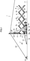
- FIG. 1 shows a scissors-type retractable structure according to the embodiment of the present invention and configured as scissors-type retractable bridge 1, which is in the course of extension.
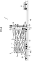
- FIG. 2 shows the scissors-type retractable bridge 1 in a standby state.
- FIG. 3 shows the scissors-type retractable bridge 1 which has been brought into an erected state from the state shown in FIG. 2 .
- This scissors-type retractable bridge 1 is extendable and retractable in an extension direction, and configured to become flat in a fully extended state.
- this scissors-type retractable bridge 1 includes at least one scissors frame 4.
- the scissors frame 4 includes a plurality of frame elements 3 (four frame elements 3 in FIG. 4 ) each of which is comprised of two frame members 2 (see FIGS.
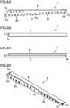
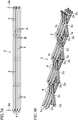
- Each frame member 2 includes a frame body 7 which has pin-insertion end holes 2d in both end portions and plurality of through holes 2b for weight reduction, and a deck member 8 provided on the upper side of the frame body 7 and configured to form part of a flat surface.
- the frame member 2 may be made of, for example, a single integral extrusion member of an aluminum alloy which includes a hollow and has a small weight and high stiffness, or a three-dimensionally optimally shaped built member.
- the frame member 2 may be configured as an assembly of the frame body 7 and the deck member 8 made of different materials.
- the frame member 2 which functions as a scissors structure and as a deck plate structure as well, leads to a decrease in the number of parts, eases the assembly, and reduces resistance caused by the geometrical structure of deck plates.
- the frame body 7 has a support notch 7a formed at its base end, and a mating support notch 7b formed at its tip end.
- the mating support notch 7b is brought into contact with, and supported on, the support notch 7a of an adjacent frame body 7.
- the support notch 7a and the mating support notch 7b need to be shaped such that the notches 7a and 7b interfere with each other only after the scissors-type retractable bridge 1 is fully extended, stabilize once the retractable bridge 1 is fully extended and positioned horizontally, and enable the retractable bridge 1 to support the weights of pedestrians and automobiles passing over the deck members 8.
- one frame element 3 includes two frame members 2. These two frame members 2 are connected to each other via a center shaft 2c which penetrates, and extends in parallel to, the pin-insertion central holes 2a formed in the central portions of the two frame members 2. This allows the two frame members 2 to pivot about the center shaft 2c just like a pair of scissors.
- the scissors frame 4 When the scissors frame 4 is in an extended state, part of the frame members 2 forming the frame elements 3 and positioned on a near side are linearly coupled to each other, and the other part of the frame members 2 forming the frame elements 3 and positioned on a far side are linearly coupled to each other. Consequently, the upper surfaces of the frame members 2 form a continuous flat surface shown in FIG. 5A . As shown in FIG.
- FIGS. 1-7B show a small number of the frame members 2 and other components, and that the number of these components is not particularly limited to this.
- FIGS. 7A and 7B it is suitable to arrange three scissors frames 4 side by side in the width direction to increase the width of the retractable bridge 1.
- the number of the scissors frames 4 to be arranged may be suitably determined according to the relation between the width of the deck member 8 and the width of a girder which is needed to allow pedestrians or vehicles to cross the retractable bridge 1.
- horizontal shafts 2e extending in the width direction of the scissors-type retractable bridge 1 are coupled respectively to the pin-insertion end holes 2d positioned above, and the pin-insertion end holes 2d positioned below.
- the frame elements 3 adjacent in the extension direction are coupled to each other.
- Long horizontal shafts 2e extending in the width direction may be used at appropriate intervals to couple the frame elements 3 arranged in the width direction to one another, which may increase the strength.
- arranging a pair of scissors frames 4 in the width direction with a spacing provided therebetween and corresponding to the distance between the wheels of an automobile (the vehicle width) allows the automobile to run on the scissors frames 4.
- a scissors linkage 6 which includes the plurality of scissors frames 4 arranged side by side toward the far side may be increased in the width to allow ordinary automobiles of different types to pass at the same time.
- the scissors-type retractable bridge 1 includes the plurality of frame elements 3 each including the frame members 2 and coupled to each other such that the resultant girder has a length desired in a spot where the retractable bridge 1 is provided.
- the scissors linkage 6 including these frame elements 3 each comprised of the frame members 2 has an end secured to a pedestal frame 10.
- This pedestal frame 10 is installed on an installation plane P where the scissors-type retractable bridge 1 is provided, and made of, for example, a welded structure having an L shape as viewed from a side.
- the pedestal frame 10 includes, on its portion which is positioned vertically in an extended state, a guide member 11 having the shape of a gutter and determining a direction in which the frame members 2 are extended.
- a roller 11a provided to the frame member 2 closest to the counter-extension direction side moves vertically in this vertical guide member 11, thereby controlling the direction in which the frame elements 3 are extended.
- the pedestal frame 10 is coupled to a base 12 having a rectangular frame shape of which the long sides extend in the extension direction such that the pedestal frame 10 may be erected and laid down.
- a pedestal frame control cylinder 13 is provided which has an end coupled to a counter-extension direction side end of the base 12, and the other end coupled to the pedestal frame 10.
- the pedestal frame 10 has its counter-extension direction side end pivotably coupled to a pivot 12a of the base 12. This configuration allows the pedestal frame 10 to be erected and laid down with respect the base 12 according to extension and retraction of the pedestal frame control cylinder 13.
- the base 12 has, at its extension direction side end, an anchor 18 to which the pedestal frame 10 is coupled and anchored.
- the anchor 18 may be omitted, and its shape is not particularly limited.
- the scissors-type retractable bridge 1 further includes an extension assistance mechanism 23 which assists the scissors linkage 6 in extending and retracting.
- the pedestal frame 10 is provided with, on both its sides in the width direction, extension speed-regulating cylinders 14 functioning as means for regulating an extension speed.
- extension speed-regulating cylinders 14 assist the scissors linkage 6 in extending and retracting.
- a first sprocket 15 is attached to an end of each extension speed-regulating cylinder 14. Extending and retracting each extension speed-regulating cylinder 14 may vary a distance between the first sprocket 15 and a second sprocket 16 which is fixed to a lower portion of the pedestal frame 10.
- An extension chain 17 is wrapped around each pair of the first and second sprockets 15 and 16. Each extension chain 17 has an end secured to the pedestal frame 10 and the other end coupled to an end of the second frame member 2 from the counter-extension direction side.
- the extension assistance mechanism 23 includes, for example, an extension cylinder 19.
- the extension cylinder 19 has a cylinder tube fixed to the base 12 and a vertical arm 19a projecting from the end of its rod.
- this arm 19a pushes, for example, the second horizontal shaft 2e from the counter-extension direction side, causing the scissors linkage 6 to start extending.
- the scissors linkage 6 then continues extending due to its own weight.
- a hydraulic device controls a flow rate of hydraulic fluid from the extension speed-regulating cylinders 14 to regulate the extension speed (a so-called meter-out control).
- the retraction may be performed in such a manner that the extension speed-regulating cylinders 14 are forced to retract by receiving supply of the hydraulic fluid so as to pull back the extension chains 17, thereby closing the opened frame members 2.
- Adjustment of the number of falls of the extension chains 17 enables regulation of the speed and distance of the movement of the extension chains 17 even if strokes of the extension speed-regulating cylinders 14 are restricted.
- An extension sheave 20 is provided at the top end of the pedestal frame 10.
- a wire 22 of a hand-operated winch 21 installed on the installation plane P is wrapped around the extension sheave 20, and an end of this wire 22 is coupled to an end of the frame member 2 at the forefront in the extension direction.
- the winch 21 may be used as a means for regulating the extension speed.
- the hand-operated winch 21 may be replaced with a hydraulic winch or an electric winch, the hand-operated winch 21 has an advantage that the extension may be performed with human power.
- An electric winch may be actuated using a battery of an automobile, if applicable.
- the pedestal frame 10 is secured to the counter-extension direction side end portion of the base 12.
- the pedestal frame control cylinder 13, the extension speed-regulating cylinders 14, and the extension cylinder 19 are all in the retracted state. Holding these cylinders in the retracted state enables the retractable bridge 1 to be maintained the standby state.
- a lock device may be separately provided to maintain in the retractable bridge 1 in the standby state.
- the retractable bridge 1 retracted into the compact standby state may be transported by trailer truck, boat, ship, large helicopter, or other means.
- a separately provided hydraulic unit is connected to the pedestal frame control cylinder 13, extension speed-regulating cylinders 14, and the extension cylinder 19.
- the pedestal frame control cylinder 13 is then extended gradually until the pedestal frame 10 enters the erected state shown in FIG. 3 . In this state, the scissors linkage 6 is still in the retracted state.
- the extension cylinder 19 is supplied with the hydraulic fluid and extended gradually. Consequently, the arm 19a of the extension cylinder 19 forces the horizontal shaft 2e extending in the width direction to slide and move, and the extension chains 17 are fed. At the same time, the hand-operated winch 21 feeds the wire 22.
- the extension speed is controlled by adjusting the amount of the hydraulic fluid discharged from the tube-rod side of the extension speed-regulating cylinders 14. Consequently, the intervals between all the frame members 2 are increased gradually. In this manner, the scissors frames 4 are extended not at once, but gradually and stably.
- each support notch 7a and the associated mating support notch 7b come into contact with each other to form a flat surface, the extension is stopped and the retractable bridge 1 stabilizes as shown in FIGS. 5A-5C .
- a locking means may be provided to stabilize the retractable bridge 1 in this state.
- a plate-like member may be placed on, and integrally and firmly secured to, the upper surfaces of the deck members 8 with bolts or other fasteners. In this manner, a temporary bridge is formed.
- the deck members 8 form a stable girder which allows passage of ordinary automobiles and pedestrians.
- the retractable bridge 1 may be transported to a spot struck by a disaster, and used to restore a damaged or washed away bridge quickly.
- retractable bridge 1 is suitably performed by, for example, manually operating the hand-operated winch 21 or forcing the extension speed-regulating cylinders 14 to retract to fold the deck members 8 together with the scissors frames 4.
- the retractable bridge 1 may be extended and retracted without difficulty, and removal of the retractable bridge 1 may be performed quite easily as well.
- the use of the hand-operated winch 21 enables the extension and retraction to be performed with human power.
- the frame members 2 of this embodiment are made of an aluminum alloy or a magnesium alloy and have a structure with a small weight and a high stiffness. Therefore, the retractable bridge 1 may be transported easily, and the strength is also ensured without difficulty.
- the upper surfaces of the frame members 2 form a flat surface. Therefore, stabilization may be achieved without using separate deck plate members.
- the upper surfaces of the frame members 2 function also as deck plates to allow pedestrians and automobiles to pass over the frame members 2. Thanks to the absence of deck plate members, unlike a bridge including deck plate members, it does not need huge force to erect the scissors-type retractable bridge 1 of this embodiment being in the horizontal position, and to bring the retractable bridge 1 into the standby state. The absence of deck plate members may result in a decrease in the number of parts, simplification of the configuration, and weight reduction.
- the plurality of scissors frames 4 arranged toward a far side form a girder when the scissors frames 4 are in the extended state.
- the width of the girder may be increased easily when the scissors frames 4 are used as the girder.
- the scissors-type retractable bridge 1 is configured such that the upper surfaces of the scissors frames 4 in the extension state form a flat surface.
- the scissors-type retractable bridge 1 has a simple configuration, is easy to transport, retract, and extend, and forms a stable structure in the extended state.
- the retractable bridge 1 of this embodiment Since the scissors-type retractable bridge 1 of this embodiment is prefabricated in, for example, a factory, the retractable bridge 1 has a high quality and a high degree of perfection. Transportation and dealing of the retractable bridge 1, which can be folded compactly, may be performed quite easily.
- the retractable bridge 1 may increase choices of countermeasures against difficult restoration work in a spot struck by a disaster, and improve conformability with the spot.
- the bridge has to be closed.
- the scissors-type retractable bridge 1 of this embodiment including the scissors linkage 6 may be used to address this problem.
- the retractable structure of the retractable bridge 1 is secured to portions receiving reaction force, on the bridge piers or bridge abutments, thereby provisionally reinforcing the aging bridge.
- the retractable bridge 1 may advantageously enable the repair of the aging bridge to be performed, while reducing burden on the aging bridge.
- this embodiment is of high utility value for landing piers of fishing ports or harbors.
- the retractable bridge 1 of this embodiment may be temporarily provided only when needed, which may avoid restriction of use of a landing pier, and damage caused by a typhoon, a storm surge, or other disasters.
- the retractable bridge 1 of this embodiment provides convenience to the users and administrator.
- the retractable bridge 1 of this embodiment may be used as an escape bridge for a middle-to-low building.
- an escape route may be ensured by extending the retractable bridge 1 to an adjacent building.
- the retractable bridge 1 of this embodiment may provide a great advantage in case of emergency.
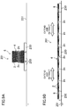
- FIG. 8 is a front view schematically showing a scissors-type retractable bridge 101 according to a first variation of this embodiment, which is being extended between suspension bridge towers 130, as an example application. Note that in the following variations, components that are the same as those shown in FIGS. 1-7B will be denoted by the corresponding reference characters, and detailed description thereof will be omitted herein.
- the scissors linkage 6 has an end secured to one of the suspension bridge towers 130, and the other end provided with an extension sheave 120 around which a wire 122 is wrapped.
- the wire 122 has an end wrapped around another extension sheave 120 provided to the other tower 130.
- the scissors linkage 6 is extended by pulling the end of the wire 122 with a crane or a winch, and the other end of the scissors linkage 6 is then secured to the latter tower 130, thereby providing a temporary scissors-type retractable bridge 101.
- wire 122 may be pulled directly with a crane or other apparatus, without being wrapped around the extension sheave 120 provided to the latter tower 130.
- This configuration eliminates conventional problems which have occurred in construction sites: It is no longer needed to assemble a bridge body temporarily and to ensure a temporary work site or space having a length equivalent to that of the bridge.
- This configuration enables the main body of a temporary bridge to be provided in a short time by using a crane, while eliminating need for a special device or need for taking great care for maintaining balance, which is required in, for example, the incremental launching method.
- FIGS. 9A and 9B schematically show a scissors-type retractable bridge 201 according to a second variation of this embodiment, which is used together with pontoons 230, as an example application.
- FIG. 9A is a front view of the retractable bridge in a standby state
- FIG. 9B is a front view of the retractable bridge in a fully extended state.
- a pontoon is a boat having a flat bottom, which is also called “flat-bottomed boat” or “ponton.” Extension of the retractable bridge 201 is performed by increasing the distance between adjacent ones of the pontoons 230 to extend the scissors linkage 6.
- the pontoons 230 coupled to each other are towed over a water surface 231 by, for example, a tugboat.
- the pontoons 230 on which the lower end portions of the scissors linkage 6 are supported are separated from each other to increase the distance therebetween until the deck members 8 become positioned horizontally and coupled to each other, thereby easily providing the temporary bridge over the water surface 231, as shown in FIG. 9B . No bridge piers are needed in this case.
- the present invention also makes it possible to easily construct, in a river or a harbor, a bridging system in which a plurality of pontoons 230 are linked via a scissors linkage 6. Gathering several pontoons 230 compactly enables a pontoon bridge system which has, by nature, a large size to be constructed easily. This system may also ensure an escape route in case of a disastrous flood.
- This variation may be applied to a case where a "gangplank" for allowing passengers of a boat to land on a shore is needed (in particular, to a conceivable situation where harbor facilities are also damaged seriously by an earthquake).
- a compact scissors linkage 6 with which a boat is equipped may be utilized flexibly, and may enable passengers of the boat to transfer safely from the boat to another boat.
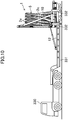
- FIG. 10 is a front view of a scissors-type retractable bridge 1 according to a third variation of this embodiment, which is placed on the trailer 331 of a trailer truck 330.
- the base 12 including the pedestal frame 10 is placed on the trailer 331 of the trailer truck 330.
- the trailer 331 is towed by the trailer truck 330 to a work site, where the scissors-type retractable bridge 1 is unloaded and its scissors linkage 6 is extended.
- the scissors-type retractable bridge 1 in the standby state is transported on the trailer 331 of the trailer truck 330.
- outriggers 332 provided to the retractable bridge 1 are extended to raise the retractable bridge 1, and the trailer truck 330 is then moved forward to place the retractable bridge 1 on the ground or any other plane.
- the scissors linkage 6 may be extended while the outriggers 332 remain extended or after the outriggers 332 are retracted. Performing the extension after placing the retractable bridge 1 on the ground or any other plane in the work site by using the outriggers 332 in this manner may enable a temporary bridge to be provided quite quickly and easily.
- the trailer 331 of the trailer truck 330 is moved to be stopped under the retractable bridge 1 held raised by the outriggers 332. Thereafter, the outriggers 332 are retracted, thereby placing the retractable bridge 1 on the trailer 331 for removal, without having to use a crane to raise the retractable bridge 1.
- the use of the outriggers 332 enables the scissors-type retractable bridge 1 to be loaded and unloaded quite easily, without having to use a special machine such as a crane.
- a fourth variation which is not shown in the drawings in detail, is configured as follows:
- the scissors-type retractable bridges 1 each of which is able to extend by itself in a cantilevered state are allowed to extend from opposite banks.
- a bent or any other support is provided at the middle between the banks to support the retractable bridges 1.
- the scissors linkages 6 of both retractable bridges 1 are coupled to each other at the middle between the banks. Thereafter, the bent or the support is removed. In this manner, a desired bridge may be constructed quickly.
- a fifth variation which is not shown in the drawings in detail, is configured as follows: A plurality of bents functioning as supports are arranged. Two scissors-type retractable bridges 1 are extended over a predetermined span in the opposite directions from an associated one of the plurality of bents. Couplings are provided between the scissors linkages 6 extending in the opposite directions and joining with each other, and the bents provided as supports are then removed. In this manner, a desired bridge may be constructed quickly.
- the embodiment described above includes the extension speed-regulating cylinders 14 including the extension chains 17 and functioning as the extension assistance mechanism 23.
- the retractable bridge 1 may be extended and retracted using a hand-operated winch 21 alone, without having to include the extension chains 17 and the extension speed-regulating cylinders 14.
- a wheel attached to the horizontal shaft 2e that is positioned toward the extension direction side may beneficially allow the scissors linkage 6 to extend smoothly.
- the present invention is useful for a scissors-type retractable bridge.
Landscapes
- Engineering & Computer Science (AREA)
- Architecture (AREA)
- Civil Engineering (AREA)
- Structural Engineering (AREA)
- Bridges Or Land Bridges (AREA)
Priority Applications (1)
| Application Number | Priority Date | Filing Date | Title |
|---|---|---|---|
| PL14895015T PL3147407T3 (pl) | 2014-06-17 | 2014-06-17 | Składana konstrukcja typu nożycowego |
Applications Claiming Priority (1)
| Application Number | Priority Date | Filing Date | Title |
|---|---|---|---|
| PCT/JP2014/003252 WO2015193930A1 (ja) | 2014-06-17 | 2014-06-17 | シザーズ式伸縮構造 |
Publications (3)
| Publication Number | Publication Date |
|---|---|
| EP3147407A1 EP3147407A1 (en) | 2017-03-29 |
| EP3147407A4 EP3147407A4 (en) | 2017-06-07 |
| EP3147407B1 true EP3147407B1 (en) | 2019-08-07 |
Family
ID=54934967
Family Applications (1)
| Application Number | Title | Priority Date | Filing Date |
|---|---|---|---|
| EP14895015.7A Active EP3147407B1 (en) | 2014-06-17 | 2014-06-17 | Scissors-type retractable structure |
Country Status (5)
| Country | Link |
|---|---|
| EP (1) | EP3147407B1 (pl) |
| JP (1) | JP6068681B2 (pl) |
| CN (1) | CN105473789B (pl) |
| PL (1) | PL3147407T3 (pl) |
| WO (1) | WO2015193930A1 (pl) |
Families Citing this family (5)
| Publication number | Priority date | Publication date | Assignee | Title |
|---|---|---|---|---|
| CN107905087A (zh) * | 2017-12-22 | 2018-04-13 | 贵州省水利水电勘测设计研究院 | 一种用于进水口的折叠式交通桥 |
| RU2687662C1 (ru) * | 2018-07-19 | 2019-05-15 | Общество с ограниченной ответственностью "Несущие системы" | Раздвижная ферма консольно-пролетного типа переменного вылета |
| CN112160229A (zh) * | 2020-10-21 | 2021-01-01 | 东南大学 | 一种应急可展斜拉桥梁及其自架设施工方法 |
| CN116791460A (zh) * | 2023-06-29 | 2023-09-22 | 江苏旭福集成科技有限公司 | 一种折叠式贝雷架及其折叠方法 |
| CN117051729B (zh) * | 2023-08-18 | 2024-05-17 | 西安公路研究院有限公司 | 一种用于钢混组合桥梁的应急抢修架设装置及方法 |
Family Cites Families (12)
| Publication number | Priority date | Publication date | Assignee | Title |
|---|---|---|---|---|
| GB1068155A (en) * | 1963-07-02 | 1967-05-10 | Sydney Howell | Structural members |
| JPS4829377Y1 (pl) * | 1969-09-24 | 1973-09-06 | ||
| PT78869A (en) * | 1984-07-09 | 1984-08-01 | Luis Gonzaga De Morais Zoio | Joined frame |
| JPS6462600A (en) * | 1987-09-01 | 1989-03-09 | Zenya Kaiyo Service Kk | Expansible transfer bridge |
| DE19747108A1 (de) * | 1997-10-24 | 1999-04-29 | Univ Magdeburg Tech | Vorrichtung zum Falten mehrerer Brückenteile einer Klappbrücke |
| US6928683B1 (en) * | 2002-06-25 | 2005-08-16 | Stuart Craig Hanson | Extendable support structures |
| JP4967117B2 (ja) * | 2005-09-14 | 2012-07-04 | 国立大学法人広島大学 | 構造体及びその主フレームの伸張・縮収装置 |
| FR2945298B1 (fr) * | 2009-05-06 | 2011-06-17 | Deschamps A & Fils Ets | Pont temporaire perfectionne |
| JP5671263B2 (ja) * | 2010-06-08 | 2015-02-18 | 星軽金属工業株式会社 | 構造体 |
| JP2014145203A (ja) * | 2013-01-29 | 2014-08-14 | Hiroshima Univ | シザーズ式伸縮構造 |
| CN203514172U (zh) * | 2013-10-21 | 2014-04-02 | 贾针 | 一种抢险装置 |
| CN103835220B (zh) * | 2014-03-06 | 2016-09-07 | 南京工业大学 | 一种快速可展式预应力钢桥 |
-
2014
- 2014-06-17 EP EP14895015.7A patent/EP3147407B1/en active Active
- 2014-06-17 JP JP2015556302A patent/JP6068681B2/ja not_active Expired - Fee Related
- 2014-06-17 WO PCT/JP2014/003252 patent/WO2015193930A1/ja not_active Ceased
- 2014-06-17 PL PL14895015T patent/PL3147407T3/pl unknown
- 2014-06-17 CN CN201480039964.5A patent/CN105473789B/zh not_active Expired - Fee Related
Non-Patent Citations (1)
| Title |
|---|
| None * |
Also Published As
| Publication number | Publication date |
|---|---|
| WO2015193930A1 (ja) | 2015-12-23 |
| CN105473789B (zh) | 2017-03-15 |
| PL3147407T3 (pl) | 2020-01-31 |
| JPWO2015193930A1 (ja) | 2017-04-20 |
| CN105473789A (zh) | 2016-04-06 |
| EP3147407A4 (en) | 2017-06-07 |
| JP6068681B2 (ja) | 2017-01-25 |
| EP3147407A1 (en) | 2017-03-29 |
Similar Documents
| Publication | Publication Date | Title |
|---|---|---|
| CN110042769B (zh) | 一种组合梁斜拉桥辅助跨全悬臂拼装施工方法 | |
| EP3147407B1 (en) | Scissors-type retractable structure | |
| CN105603881B (zh) | 一种大型跨海拱桥的整体架设系统及其施工方法 | |
| CN104727227B (zh) | 一种中承式钢箱系杆拱桥敞口格构式钢梁整节段架设方法 | |
| US20110283467A1 (en) | simple tower instrument construction and its method | |
| CN103510475B (zh) | 三主桁钢桁梁单联双跨无导梁长距离顶推施工方法 | |
| CN105603861B (zh) | 一种整体拼装浮运提升拱桥及其施工方法 | |
| JP2014145203A (ja) | シザーズ式伸縮構造 | |
| CN103147405B (zh) | 斜主桁斜拉桥钢梁架设方法 | |
| CN106939553B (zh) | 一种钢桥面和钢箱拱肋安装方法 | |
| CN110485255A (zh) | 一种折叠式应急桥梁及使用方法 | |
| CN104018426B (zh) | 一种钢桁梁安装方法 | |
| CN111188274A (zh) | 大跨钢-混组合桥大节段钢桁梁移运梁系统及施工方法 | |
| CN102367650A (zh) | 一种钢管拱桥的施工方法 | |
| EP4127453B1 (de) | Verfahren zum errichten einer windenergieanlage mit einem turm und zwei sich vom turm erstreckenden auslegern | |
| CN107841936B (zh) | 一种可展桥梁 | |
| WO2018054532A1 (de) | Bauwerk zur errichtung an gewässeroberflächen und verfahren zu seiner errichtung | |
| CN117802871B (zh) | 一种浮桥整体的施工工艺 | |
| CN106120565B (zh) | 大跨度偏心斜靠式钢箱系杆拱桥浮拖架设施工系统 | |
| CN104775365A (zh) | 一种斜拉桥施工方法 | |
| CN112144413B (zh) | 一种山区钢混组合梁整跨原位拼装架设方法 | |
| DE19911617A1 (de) | Montagekran | |
| RU2737748C1 (ru) | Установка в проектное положение пролетного строения подводного автодорожного разборного моста совместно с одной промежуточной свайно-башмачной опорой | |
| RU2534557C1 (ru) | Способ демонтажа пролетного строения моста с использованием вантовой системы | |
| CN222119906U (zh) | 通航孔提升栈桥的提升架和通航孔提升栈桥 |
Legal Events
| Date | Code | Title | Description |
|---|---|---|---|
| STAA | Information on the status of an ep patent application or granted ep patent |
Free format text: STATUS: THE INTERNATIONAL PUBLICATION HAS BEEN MADE |
|
| PUAI | Public reference made under article 153(3) epc to a published international application that has entered the european phase |
Free format text: ORIGINAL CODE: 0009012 |
|
| STAA | Information on the status of an ep patent application or granted ep patent |
Free format text: STATUS: REQUEST FOR EXAMINATION WAS MADE |
|
| 17P | Request for examination filed |
Effective date: 20161221 |
|
| AK | Designated contracting states |
Kind code of ref document: A1 Designated state(s): AL AT BE BG CH CY CZ DE DK EE ES FI FR GB GR HR HU IE IS IT LI LT LU LV MC MK MT NL NO PL PT RO RS SE SI SK SM TR |
|
| AX | Request for extension of the european patent |
Extension state: BA ME |
|
| A4 | Supplementary search report drawn up and despatched |
Effective date: 20170510 |
|
| RIC1 | Information provided on ipc code assigned before grant |
Ipc: E04B 1/34 20060101ALI20170503BHEP Ipc: E01D 15/12 20060101AFI20170503BHEP Ipc: E01D 15/14 20060101ALI20170503BHEP |
|
| DAX | Request for extension of the european patent (deleted) | ||
| STAA | Information on the status of an ep patent application or granted ep patent |
Free format text: STATUS: EXAMINATION IS IN PROGRESS |
|
| 17Q | First examination report despatched |
Effective date: 20180522 |
|
| RAP1 | Party data changed (applicant data changed or rights of an application transferred) |
Owner name: HOSHIKEI KINZOKU KOGYO CO., LTD. Owner name: SANKYO TATEYAMA, INC. Owner name: HIROSHIMA UNIVERSITY Owner name: JAPAN CONSTRUCTION MACHINERY AND CONSTRUCTION ASSO |
|
| RAP1 | Party data changed (applicant data changed or rights of an application transferred) |
Owner name: JAPAN CONSTRUCTION MACHINERY AND CONSTRUCTION ASSO Owner name: INSTITUE OF FUNDAMENTAL TECHNOLOGICAL RESEARCH POL Owner name: HIROSHIMA UNIVERSITY Owner name: SANKYO TATEYAMA, INC. Owner name: HOSHIKEI KINZOKU KOGYO CO., LTD. |
|
| GRAP | Despatch of communication of intention to grant a patent |
Free format text: ORIGINAL CODE: EPIDOSNIGR1 |
|
| STAA | Information on the status of an ep patent application or granted ep patent |
Free format text: STATUS: GRANT OF PATENT IS INTENDED |
|
| INTG | Intention to grant announced |
Effective date: 20190206 |
|
| GRAS | Grant fee paid |
Free format text: ORIGINAL CODE: EPIDOSNIGR3 |
|
| GRAA | (expected) grant |
Free format text: ORIGINAL CODE: 0009210 |
|
| STAA | Information on the status of an ep patent application or granted ep patent |
Free format text: STATUS: THE PATENT HAS BEEN GRANTED |
|
| AK | Designated contracting states |
Kind code of ref document: B1 Designated state(s): AL AT BE BG CH CY CZ DE DK EE ES FI FR GB GR HR HU IE IS IT LI LT LU LV MC MK MT NL NO PL PT RO RS SE SI SK SM TR |
|
| REG | Reference to a national code |
Ref country code: GB Ref legal event code: FG4D |
|
| REG | Reference to a national code |
Ref country code: CH Ref legal event code: EP Ref country code: AT Ref legal event code: REF Ref document number: 1164077 Country of ref document: AT Kind code of ref document: T Effective date: 20190815 |
|
| REG | Reference to a national code |
Ref country code: DE Ref legal event code: R096 Ref document number: 602014051579 Country of ref document: DE |
|
| REG | Reference to a national code |
Ref country code: IE Ref legal event code: FG4D |
|
| REG | Reference to a national code |
Ref country code: NL Ref legal event code: MP Effective date: 20190807 |
|
| REG | Reference to a national code |
Ref country code: LT Ref legal event code: MG4D |
|
| PG25 | Lapsed in a contracting state [announced via postgrant information from national office to epo] |
Ref country code: LT Free format text: LAPSE BECAUSE OF FAILURE TO SUBMIT A TRANSLATION OF THE DESCRIPTION OR TO PAY THE FEE WITHIN THE PRESCRIBED TIME-LIMIT Effective date: 20190807 Ref country code: HR Free format text: LAPSE BECAUSE OF FAILURE TO SUBMIT A TRANSLATION OF THE DESCRIPTION OR TO PAY THE FEE WITHIN THE PRESCRIBED TIME-LIMIT Effective date: 20190807 Ref country code: SE Free format text: LAPSE BECAUSE OF FAILURE TO SUBMIT A TRANSLATION OF THE DESCRIPTION OR TO PAY THE FEE WITHIN THE PRESCRIBED TIME-LIMIT Effective date: 20190807 Ref country code: BG Free format text: LAPSE BECAUSE OF FAILURE TO SUBMIT A TRANSLATION OF THE DESCRIPTION OR TO PAY THE FEE WITHIN THE PRESCRIBED TIME-LIMIT Effective date: 20191107 Ref country code: NL Free format text: LAPSE BECAUSE OF FAILURE TO SUBMIT A TRANSLATION OF THE DESCRIPTION OR TO PAY THE FEE WITHIN THE PRESCRIBED TIME-LIMIT Effective date: 20190807 Ref country code: PT Free format text: LAPSE BECAUSE OF FAILURE TO SUBMIT A TRANSLATION OF THE DESCRIPTION OR TO PAY THE FEE WITHIN THE PRESCRIBED TIME-LIMIT Effective date: 20191209 Ref country code: FI Free format text: LAPSE BECAUSE OF FAILURE TO SUBMIT A TRANSLATION OF THE DESCRIPTION OR TO PAY THE FEE WITHIN THE PRESCRIBED TIME-LIMIT Effective date: 20190807 Ref country code: NO Free format text: LAPSE BECAUSE OF FAILURE TO SUBMIT A TRANSLATION OF THE DESCRIPTION OR TO PAY THE FEE WITHIN THE PRESCRIBED TIME-LIMIT Effective date: 20191107 |
|
| REG | Reference to a national code |
Ref country code: AT Ref legal event code: MK05 Ref document number: 1164077 Country of ref document: AT Kind code of ref document: T Effective date: 20190807 |
|
| PG25 | Lapsed in a contracting state [announced via postgrant information from national office to epo] |
Ref country code: RS Free format text: LAPSE BECAUSE OF FAILURE TO SUBMIT A TRANSLATION OF THE DESCRIPTION OR TO PAY THE FEE WITHIN THE PRESCRIBED TIME-LIMIT Effective date: 20190807 Ref country code: IS Free format text: LAPSE BECAUSE OF FAILURE TO SUBMIT A TRANSLATION OF THE DESCRIPTION OR TO PAY THE FEE WITHIN THE PRESCRIBED TIME-LIMIT Effective date: 20191207 Ref country code: ES Free format text: LAPSE BECAUSE OF FAILURE TO SUBMIT A TRANSLATION OF THE DESCRIPTION OR TO PAY THE FEE WITHIN THE PRESCRIBED TIME-LIMIT Effective date: 20190807 Ref country code: LV Free format text: LAPSE BECAUSE OF FAILURE TO SUBMIT A TRANSLATION OF THE DESCRIPTION OR TO PAY THE FEE WITHIN THE PRESCRIBED TIME-LIMIT Effective date: 20190807 Ref country code: GR Free format text: LAPSE BECAUSE OF FAILURE TO SUBMIT A TRANSLATION OF THE DESCRIPTION OR TO PAY THE FEE WITHIN THE PRESCRIBED TIME-LIMIT Effective date: 20191108 Ref country code: AL Free format text: LAPSE BECAUSE OF FAILURE TO SUBMIT A TRANSLATION OF THE DESCRIPTION OR TO PAY THE FEE WITHIN THE PRESCRIBED TIME-LIMIT Effective date: 20190807 |
|
| PG25 | Lapsed in a contracting state [announced via postgrant information from national office to epo] |
Ref country code: TR Free format text: LAPSE BECAUSE OF FAILURE TO SUBMIT A TRANSLATION OF THE DESCRIPTION OR TO PAY THE FEE WITHIN THE PRESCRIBED TIME-LIMIT Effective date: 20190807 |
|
| PG25 | Lapsed in a contracting state [announced via postgrant information from national office to epo] |
Ref country code: DK Free format text: LAPSE BECAUSE OF FAILURE TO SUBMIT A TRANSLATION OF THE DESCRIPTION OR TO PAY THE FEE WITHIN THE PRESCRIBED TIME-LIMIT Effective date: 20190807 Ref country code: AT Free format text: LAPSE BECAUSE OF FAILURE TO SUBMIT A TRANSLATION OF THE DESCRIPTION OR TO PAY THE FEE WITHIN THE PRESCRIBED TIME-LIMIT Effective date: 20190807 Ref country code: EE Free format text: LAPSE BECAUSE OF FAILURE TO SUBMIT A TRANSLATION OF THE DESCRIPTION OR TO PAY THE FEE WITHIN THE PRESCRIBED TIME-LIMIT Effective date: 20190807 Ref country code: RO Free format text: LAPSE BECAUSE OF FAILURE TO SUBMIT A TRANSLATION OF THE DESCRIPTION OR TO PAY THE FEE WITHIN THE PRESCRIBED TIME-LIMIT Effective date: 20190807 Ref country code: IT Free format text: LAPSE BECAUSE OF FAILURE TO SUBMIT A TRANSLATION OF THE DESCRIPTION OR TO PAY THE FEE WITHIN THE PRESCRIBED TIME-LIMIT Effective date: 20190807 |
|
| PG25 | Lapsed in a contracting state [announced via postgrant information from national office to epo] |
Ref country code: SM Free format text: LAPSE BECAUSE OF FAILURE TO SUBMIT A TRANSLATION OF THE DESCRIPTION OR TO PAY THE FEE WITHIN THE PRESCRIBED TIME-LIMIT Effective date: 20190807 Ref country code: IS Free format text: LAPSE BECAUSE OF FAILURE TO SUBMIT A TRANSLATION OF THE DESCRIPTION OR TO PAY THE FEE WITHIN THE PRESCRIBED TIME-LIMIT Effective date: 20200224 Ref country code: SK Free format text: LAPSE BECAUSE OF FAILURE TO SUBMIT A TRANSLATION OF THE DESCRIPTION OR TO PAY THE FEE WITHIN THE PRESCRIBED TIME-LIMIT Effective date: 20190807 Ref country code: CZ Free format text: LAPSE BECAUSE OF FAILURE TO SUBMIT A TRANSLATION OF THE DESCRIPTION OR TO PAY THE FEE WITHIN THE PRESCRIBED TIME-LIMIT Effective date: 20190807 |
|
| REG | Reference to a national code |
Ref country code: DE Ref legal event code: R097 Ref document number: 602014051579 Country of ref document: DE |
|
| PLBE | No opposition filed within time limit |
Free format text: ORIGINAL CODE: 0009261 |
|
| STAA | Information on the status of an ep patent application or granted ep patent |
Free format text: STATUS: NO OPPOSITION FILED WITHIN TIME LIMIT |
|
| PG2D | Information on lapse in contracting state deleted |
Ref country code: IS |
|
| 26N | No opposition filed |
Effective date: 20200603 |
|
| PG25 | Lapsed in a contracting state [announced via postgrant information from national office to epo] |
Ref country code: SI Free format text: LAPSE BECAUSE OF FAILURE TO SUBMIT A TRANSLATION OF THE DESCRIPTION OR TO PAY THE FEE WITHIN THE PRESCRIBED TIME-LIMIT Effective date: 20190807 |
|
| PG25 | Lapsed in a contracting state [announced via postgrant information from national office to epo] |
Ref country code: MC Free format text: LAPSE BECAUSE OF FAILURE TO SUBMIT A TRANSLATION OF THE DESCRIPTION OR TO PAY THE FEE WITHIN THE PRESCRIBED TIME-LIMIT Effective date: 20190807 |
|
| REG | Reference to a national code |
Ref country code: CH Ref legal event code: PL |
|
| GBPC | Gb: european patent ceased through non-payment of renewal fee |
Effective date: 20200617 |
|
| PG25 | Lapsed in a contracting state [announced via postgrant information from national office to epo] |
Ref country code: LU Free format text: LAPSE BECAUSE OF NON-PAYMENT OF DUE FEES Effective date: 20200617 |
|
| REG | Reference to a national code |
Ref country code: BE Ref legal event code: MM Effective date: 20200630 |
|
| PG25 | Lapsed in a contracting state [announced via postgrant information from national office to epo] |
Ref country code: FR Free format text: LAPSE BECAUSE OF NON-PAYMENT OF DUE FEES Effective date: 20200630 Ref country code: LI Free format text: LAPSE BECAUSE OF NON-PAYMENT OF DUE FEES Effective date: 20200630 Ref country code: CH Free format text: LAPSE BECAUSE OF NON-PAYMENT OF DUE FEES Effective date: 20200630 Ref country code: IE Free format text: LAPSE BECAUSE OF NON-PAYMENT OF DUE FEES Effective date: 20200617 Ref country code: GB Free format text: LAPSE BECAUSE OF NON-PAYMENT OF DUE FEES Effective date: 20200617 |
|
| PG25 | Lapsed in a contracting state [announced via postgrant information from national office to epo] |
Ref country code: BE Free format text: LAPSE BECAUSE OF NON-PAYMENT OF DUE FEES Effective date: 20200630 |
|
| PG25 | Lapsed in a contracting state [announced via postgrant information from national office to epo] |
Ref country code: MT Free format text: LAPSE BECAUSE OF FAILURE TO SUBMIT A TRANSLATION OF THE DESCRIPTION OR TO PAY THE FEE WITHIN THE PRESCRIBED TIME-LIMIT Effective date: 20190807 Ref country code: CY Free format text: LAPSE BECAUSE OF FAILURE TO SUBMIT A TRANSLATION OF THE DESCRIPTION OR TO PAY THE FEE WITHIN THE PRESCRIBED TIME-LIMIT Effective date: 20190807 |
|
| PG25 | Lapsed in a contracting state [announced via postgrant information from national office to epo] |
Ref country code: MK Free format text: LAPSE BECAUSE OF FAILURE TO SUBMIT A TRANSLATION OF THE DESCRIPTION OR TO PAY THE FEE WITHIN THE PRESCRIBED TIME-LIMIT Effective date: 20190807 |
|
| PGFP | Annual fee paid to national office [announced via postgrant information from national office to epo] |
Ref country code: DE Payment date: 20220620 Year of fee payment: 9 |
|
| REG | Reference to a national code |
Ref country code: DE Ref legal event code: R119 Ref document number: 602014051579 Country of ref document: DE |
|
| PG25 | Lapsed in a contracting state [announced via postgrant information from national office to epo] |
Ref country code: DE Free format text: LAPSE BECAUSE OF NON-PAYMENT OF DUE FEES Effective date: 20240103 |
|
| PGFP | Annual fee paid to national office [announced via postgrant information from national office to epo] |
Ref country code: PL Payment date: 20250410 Year of fee payment: 12 |