EP3146208B1 - Axialkolbenmaschine - Google Patents
Axialkolbenmaschine Download PDFInfo
- Publication number
- EP3146208B1 EP3146208B1 EP15723031.9A EP15723031A EP3146208B1 EP 3146208 B1 EP3146208 B1 EP 3146208B1 EP 15723031 A EP15723031 A EP 15723031A EP 3146208 B1 EP3146208 B1 EP 3146208B1
- Authority
- EP
- European Patent Office
- Prior art keywords
- sliding block
- spherical bearing
- piston
- axial piston
- piston machine
- Prior art date
- Legal status (The legal status is an assumption and is not a legal conclusion. Google has not performed a legal analysis and makes no representation as to the accuracy of the status listed.)
- Not-in-force
Links
- 238000000576 coating method Methods 0.000 claims description 35
- 239000011248 coating agent Substances 0.000 claims description 32
- 229920001343 polytetrafluoroethylene Polymers 0.000 claims description 18
- 239000004810 polytetrafluoroethylene Substances 0.000 claims description 18
- 238000005304 joining Methods 0.000 claims description 10
- 239000002184 metal Substances 0.000 claims description 9
- 239000004033 plastic Substances 0.000 claims description 9
- 229920000642 polymer Polymers 0.000 claims description 9
- -1 polytetrafluoroethylene Polymers 0.000 claims description 9
- 238000011084 recovery Methods 0.000 claims description 8
- 238000005476 soldering Methods 0.000 claims description 5
- 238000003466 welding Methods 0.000 claims description 5
- 238000009423 ventilation Methods 0.000 claims 1
- 238000004519 manufacturing process Methods 0.000 description 11
- 238000002485 combustion reaction Methods 0.000 description 8
- 239000007789 gas Substances 0.000 description 7
- 230000002349 favourable effect Effects 0.000 description 5
- 238000003780 insertion Methods 0.000 description 5
- 230000037431 insertion Effects 0.000 description 5
- 239000000243 solution Substances 0.000 description 5
- 239000000446 fuel Substances 0.000 description 4
- 239000012530 fluid Substances 0.000 description 3
- 238000004026 adhesive bonding Methods 0.000 description 2
- 230000001419 dependent effect Effects 0.000 description 2
- 238000002347 injection Methods 0.000 description 2
- 239000007924 injection Substances 0.000 description 2
- 238000000034 method Methods 0.000 description 2
- 210000002445 nipple Anatomy 0.000 description 2
- OKTJSMMVPCPJKN-UHFFFAOYSA-N Carbon Chemical compound [C] OKTJSMMVPCPJKN-UHFFFAOYSA-N 0.000 description 1
- 238000007664 blowing Methods 0.000 description 1
- 229910052799 carbon Inorganic materials 0.000 description 1
- 238000005266 casting Methods 0.000 description 1
- 230000000295 complement effect Effects 0.000 description 1
- 230000006835 compression Effects 0.000 description 1
- 238000007906 compression Methods 0.000 description 1
- 229910003460 diamond Inorganic materials 0.000 description 1
- 239000010432 diamond Substances 0.000 description 1
- 210000003746 feather Anatomy 0.000 description 1
- 230000004941 influx Effects 0.000 description 1
- 238000002955 isolation Methods 0.000 description 1
- 238000003754 machining Methods 0.000 description 1
- 239000000463 material Substances 0.000 description 1
- 238000005259 measurement Methods 0.000 description 1
- 238000003825 pressing Methods 0.000 description 1
- 239000002918 waste heat Substances 0.000 description 1
Images



Classifications
-
- F—MECHANICAL ENGINEERING; LIGHTING; HEATING; WEAPONS; BLASTING
- F01—MACHINES OR ENGINES IN GENERAL; ENGINE PLANTS IN GENERAL; STEAM ENGINES
- F01B—MACHINES OR ENGINES, IN GENERAL OR OF POSITIVE-DISPLACEMENT TYPE, e.g. STEAM ENGINES
- F01B3/00—Reciprocating-piston machines or engines with cylinder axes coaxial with, or parallel or inclined to, main shaft axis
- F01B3/0002—Reciprocating-piston machines or engines with cylinder axes coaxial with, or parallel or inclined to, main shaft axis having stationary cylinders
- F01B3/0017—Component parts, details, e.g. sealings, lubrication
- F01B3/0023—Actuating or actuated elements
- F01B3/0026—Actuating or actuated element bearing means or driving or driven axis bearing means
-
- F—MECHANICAL ENGINEERING; LIGHTING; HEATING; WEAPONS; BLASTING
- F01—MACHINES OR ENGINES IN GENERAL; ENGINE PLANTS IN GENERAL; STEAM ENGINES
- F01B—MACHINES OR ENGINES, IN GENERAL OR OF POSITIVE-DISPLACEMENT TYPE, e.g. STEAM ENGINES
- F01B3/00—Reciprocating-piston machines or engines with cylinder axes coaxial with, or parallel or inclined to, main shaft axis
- F01B3/0082—Details
- F01B3/0085—Pistons
- F01B3/0088—Piston shoe retaining means
-
- F—MECHANICAL ENGINEERING; LIGHTING; HEATING; WEAPONS; BLASTING
- F04—POSITIVE - DISPLACEMENT MACHINES FOR LIQUIDS; PUMPS FOR LIQUIDS OR ELASTIC FLUIDS
- F04B—POSITIVE-DISPLACEMENT MACHINES FOR LIQUIDS; PUMPS
- F04B27/00—Multi-cylinder pumps specially adapted for elastic fluids and characterised by number or arrangement of cylinders
- F04B27/08—Multi-cylinder pumps specially adapted for elastic fluids and characterised by number or arrangement of cylinders having cylinders coaxial with, or parallel or inclined to, main shaft axis
- F04B27/0873—Component parts, e.g. sealings; Manufacturing or assembly thereof
- F04B27/0878—Pistons
-
- F—MECHANICAL ENGINEERING; LIGHTING; HEATING; WEAPONS; BLASTING
- F04—POSITIVE - DISPLACEMENT MACHINES FOR LIQUIDS; PUMPS FOR LIQUIDS OR ELASTIC FLUIDS
- F04B—POSITIVE-DISPLACEMENT MACHINES FOR LIQUIDS; PUMPS
- F04B27/00—Multi-cylinder pumps specially adapted for elastic fluids and characterised by number or arrangement of cylinders
- F04B27/08—Multi-cylinder pumps specially adapted for elastic fluids and characterised by number or arrangement of cylinders having cylinders coaxial with, or parallel or inclined to, main shaft axis
- F04B27/0873—Component parts, e.g. sealings; Manufacturing or assembly thereof
- F04B27/0878—Pistons
- F04B27/0882—Pistons piston shoe retaining means
-
- F—MECHANICAL ENGINEERING; LIGHTING; HEATING; WEAPONS; BLASTING
- F04—POSITIVE - DISPLACEMENT MACHINES FOR LIQUIDS; PUMPS FOR LIQUIDS OR ELASTIC FLUIDS
- F04B—POSITIVE-DISPLACEMENT MACHINES FOR LIQUIDS; PUMPS
- F04B27/00—Multi-cylinder pumps specially adapted for elastic fluids and characterised by number or arrangement of cylinders
- F04B27/08—Multi-cylinder pumps specially adapted for elastic fluids and characterised by number or arrangement of cylinders having cylinders coaxial with, or parallel or inclined to, main shaft axis
- F04B27/10—Multi-cylinder pumps specially adapted for elastic fluids and characterised by number or arrangement of cylinders having cylinders coaxial with, or parallel or inclined to, main shaft axis having stationary cylinders
- F04B27/1036—Component parts, details, e.g. sealings, lubrication
- F04B27/1045—Cylinders
-
- F—MECHANICAL ENGINEERING; LIGHTING; HEATING; WEAPONS; BLASTING
- F04—POSITIVE - DISPLACEMENT MACHINES FOR LIQUIDS; PUMPS FOR LIQUIDS OR ELASTIC FLUIDS
- F04B—POSITIVE-DISPLACEMENT MACHINES FOR LIQUIDS; PUMPS
- F04B27/00—Multi-cylinder pumps specially adapted for elastic fluids and characterised by number or arrangement of cylinders
- F04B27/08—Multi-cylinder pumps specially adapted for elastic fluids and characterised by number or arrangement of cylinders having cylinders coaxial with, or parallel or inclined to, main shaft axis
- F04B27/10—Multi-cylinder pumps specially adapted for elastic fluids and characterised by number or arrangement of cylinders having cylinders coaxial with, or parallel or inclined to, main shaft axis having stationary cylinders
- F04B27/1036—Component parts, details, e.g. sealings, lubrication
- F04B27/1054—Actuating elements
Definitions
- the present invention relates to an axial piston machine with a shaft which is non-rotatably connected to a swash plate, according to the preamble of claim 1.
- the invention also relates to a heat recovery system with such an axial piston machine.
- a generic axial piston machine with a shaft which is rotatably connected to a swash plate.
- a plurality of cylinders are arranged, in each of which built and hollow pistons are arranged translationally adjustable.
- Each of these pistons is coupled via an associated spherical bearing and a sliding block with the swash plate, whereby a movement of the respective piston causes a drive of the swash plate and thus a driving of the shaft.
- each inlet opening of a cylinder is swept once over a control disk with an eccentrically arranged passage opening at each revolution and thereby supplied to the respective cylinder working fluid.
- the present invention therefore deals with the problem of providing for an axial piston machine of the generic type an improved or at least one alternative embodiment, which is characterized in particular by an improved spherical bearing.
- the present invention is based on the general idea, a spherical bearing of an axial piston machine no longer as usual in one piece or even in one piece, but now multi-part form and thereby significantly easier to produce.
- the spherical bearing is part of an axial piston according to the invention, which has a shaft which is rotatably connected to a swash plate.
- a shaft which is rotatably connected to a swash plate.
- Each of these pistons is coupled via the said spherical bearing and at least one sliding block with the swash plate.
- an inlet opening is associated with the cylinder, the axial piston machine additionally having a control disk with an eccentrically arranged passage opening, which sweeps over each inlet opening once each revolution of the control disk and thereby directs working medium, for example exhaust gas, into the associated cylinder.
- working medium for example exhaust gas
- the spherical bearing is made in two parts and has a first and a second part, these two parts each having a receptacle or a receiving tray for a sliding block.
- the spherical bearing is made in two parts with a first and a second part, wherein the first part is connected to the piston skirt and the second part has two receptacles or two receiving shells for the sliding block.
- the two parts of the spherical bearing, one of which forms a head of the respective piston are firmly connected to each other, for example thermally joined together, welded together, glued, soldered or caulked.
- the second part of the spherical bearing is formed as a formed sheet metal bridge and thereby produced for example from a thick-walled sheet metal.
- a design of the second part as a sintered part is conceivable. It is advantageous if the formed sheet metal bridge is connected to the first part of the spherical bearing by a press fit, welding, soldering and / or thermal joining.
- At least one receptacle or receptacle has a coating, in particular a polymer coating, a DLC coating or a polytetrafluoroethylene coating (PTFE) or is nitrided.
- a coating in particular a polymer coating, a DLC coating or a polytetrafluoroethylene coating (PTFE) or is nitrided.
- PTFE polytetrafluoroethylene coating
- a receiving tray made of plastic and / or injected into an associated receptacle of the spherical bearing This can be done in particular on the counter-pressure side of the piston. Due to the design of the receiving bowl made of plastic or the injection of the same in the associated recording of the spherical bearing can turn a comparatively inexpensive, yet wear-resistant and low-friction spherical bearing can be created.
- the recording can be measured prior to insertion of the receiving tray and thereby be paired with the associated receiving tray, which in turn is dimensioned so dimensioned that it compensates for manufacturing tolerances.
- the spherical bearing can be adjusted to use a uniformly manufactured (same size) sliding block and the tolerance chain can be reduced down to the top dead center of the piston. Since every tolerance at the residual gas space of the piston at the top dead center towards the cylinder end means a reduction of the efficiency, the compensation of manufacturing tolerances by the described measurement and pairing of the receptacle with the receptacle is particularly advantageous.
- the spherical bearing is firmly connected to the associated piston and has a bore parallel to the piston axis, into which the respective receiving cup can be inserted.
- the associated receiving tray has a nipple or extension, which positively engages in the associated bore and thereby allows a positive insertion of the receiving tray in the receptacle of the spherical bearing.
- At least one receiving tray is biased by means of a screw or a spring, in particular by means of a disc spring, in particular from the counter-pressure side against the associated sliding block.
- At least one sliding block made of plastic in particular of a polymer with polytetrafluoroethylene (PTFE) is formed.
- PTFE polytetrafluoroethylene
- a favorable possibility provides that the receptacle and the sliding block are shaped such that the sliding block is in contact with the receptacle in an annular contact area, or that the receptacle shell and the sliding block are shaped such that the sliding block contacts in an annular contact area with the receiving tray is.
- the sliding block is of hemispherical design and if the annular contact area lies in an angular range of 30 ° to 57 ° relative to a piston axis, relative to a ball center of the sliding block.
- the receptacle or the receiving tray has an inner contour which is formed from an inner side of a hollow ball rotating about a circular path, wherein the center of the circular path is located on a piston axis and the circular path is in a plane extending substantially perpendicular to the vertical axis.
- the receptacle or the receiving tray can be formed such that a hemispherical sliding block is in contact with the receptacle or the receiving tray in an annular contact area.
- At least one piston of the axial piston machine according to the invention may be designed as a built and hollow piston and have a piston skirt made of a tube, whereby the piston itself not only comparatively inexpensive, but also can be easily formed, which in particular when using the axial piston machine according to the invention in a Motor vehicle fuel can be saved.
- the piston is usually composed of the previously described piston skirt, a piston crown and the spherical bearing, these components, for example, thermally joined together, glued together, welded or can be soldered. This non-exhaustive enumeration already gives an idea of how manifold the connection possibilities of the individual components of the piston are designed. In theory, of course, a compression of the individual parts is conceivable with each other.
- the piston skirt is formed from a deep-drawn tube and has a closed piston crown.
- the piston can be made more diverse and inexpensive.
- the piston skirt is formed from a drawn tube which is formed by means of cold, warm or hot forming.
- the piston skirt has a coating, in particular a polymer coating, a DLC coating (Diamond Like Carbon) or a polytetrafluoroethylene coating (PTFE) or is nitrided.
- a coating in particular a polymer coating, a DLC coating (Diamond Like Carbon) or a polytetrafluoroethylene coating (PTFE) or is nitrided.
- the piston skirt is crowned.
- the piston skirt may be concave in order to counteract a possible widening of the piston by the joining of the piston skirt with the spherical bearing.
- the piston is elliptical, i. has a non-circular outer contour, whereby a rotation of the same about its piston axis can be prevented.
- the piston skirt has at least two sections in the axial direction, which differ by an outer diameter and / or by an inner diameter. In this way, a possible expansion of the piston can be counteracted by the joining of the piston skirt with the spherical bearing.
- a particularly favorable solution provides that the piston skirt is constructed in two parts in the axial direction and that the two parts are connected to one another by means of thermal joining, gluing, welding or soldering.
- the piston skirt and thus the piston can be adapted even more flexibly, so that different advantages described above can be combined.
- a cylinder liner in at least one cylinder, can be provided, which has, for example, wear and friction-reducing surface properties, which in turn enables a particularly low-wear and smooth adjustment of the piston in the cylinder.
- the cylinder liner has a coating, in particular a polymer coating, a DLC coating or a polytetrafluoroethylene coating (PTFE) or nitrided. These coatings not only allow a reduction in the frictional resistance, but also an increase in the wear resistance, so that such a coating allows a smooth and at the same time wear-resistant guiding of the piston in the cylinder.
- the piston head can also be arranged in the inlet opening at least partially engaging nose, which can be generally referred to as an extension, and which is designed such that even gas, in particular gaseous working medium which is expanded, for blowing on and pressing the piston can pass through the inlet opening, however, unnecessary dead space, which negatively affects the efficiency, is filled.
- a nose or projection may be used together with the piston head, i. in particular, in one piece, be made with this.
- At least one spherical bearing on a vent hole which connects a piston interior with the environment.
- an anti-rotation which prevents rotation of the piston in the cylinder.
- the rotation can be - as described in the previous paragraphs - designed over a non-circular outer contour of the piston and a suitably designed inner contour of the cylinder, or by a groove and a pin engaging therein, wherein the pin is arranged on the spherical bearing and the groove on a housing, or vice versa.
- the rotation can be designed by a groove and a key engaging therein, wherein the feather key on the spherical bearing and the groove is arranged on a housing, or vice versa.
- the groove is formed by at least one guide ring arranged in the housing.
- the guide ring may be, for example, a formed sheet metal.
- the guide ring can be produced easily and inexpensively.
- the guide ring is held by a latching connection in the housing.
- the latching connection can preferably be formed by a recess in the housing, which defines a position of the guide ring on the periphery.
- the depression can for example be introduced during casting or by machining.
- the guide ring has a collar, with which the guide ring is clamped between two housing parts.
- the axial piston machine according to the invention is particularly preferably used in a heat recovery system of a motor vehicle, since over half of the energy stored in the fuel is lost as waste heat and such a heat recovery system with the axial piston according to the invention can help to use the fuel more efficient and thus the degree of recovery of the motor vehicle.
- FIGS. 1 and 2 has an axial piston machine 1 according to the invention, which may be part of a heat recovery system 2 of a motor vehicle, not shown in detail, for example, a shaft 3, which is rotatably connected to a swash plate 4.
- a shaft 3 which is rotatably connected to a swash plate 4.
- Each of these pistons 6 is coupled via a spherical bearing 7 and a sliding block 8 with the swash plate 4 for driving the shaft 3.
- Each cylinder 5 is also associated with an inlet opening 9, which is each covered by a control disk 10.
- This control disk 10 has an eccentrically arranged passage opening 11 and is also rotatably connected to the shaft 3. During each revolution of the control disk 10 whose passage opening 11 passes once each inlet opening 9 of a cylinder 5 and thereby allows access of working fluid in the associated cylinder 5. The working fluid is thereby previously collected in a plenum 12 under pressure, said plenum 12, for example, with a circuit of a heat recovery system 2 is connected.
- the inlet opening 9 is arranged in a cylinder cover 13 and aligned in exactly one rotational position of the control disk 10 with the through hole 11. Between the cylinder cover 13 and the control disk 10, a seal 14 is arranged, which seals the cavity 12 relative to the cylinder 5.
- the spherical bearing 7 is now a multi-part, ie composed of at least two components, whereby its manufacturability can be significantly simplified.
- the spherical bearing 7 according to the FIG. 1 so you can see that this is made in two parts, with a first part 15 and a second part 16, wherein the two parts 15, 16 each have a receptacle 17 (see FIG. FIG. 1 ) or a receiving tray 18 (see. FIGS. 2 to 5 ) exhibit.
- the second part 16 of the spherical bearing 7 can be formed in a cost effective manner as a formed sheet metal bridge, which in particular the production of the spherical bearing 7 is cheaper and easier.
- the spherical bearing 7, in particular the receptacles 17 and the receiving trays 18 can be easily reworked or even processed, whereby not only a higher quality, but also a simpler production is possible.
- the second part 16, in particular the formed sheet metal bridge connected to the first part 15 of the spherical bearing 7 by a press fit, welding, soldering and / or thermal joining.
- At least one of the receptacles 17 or the receiving shells 18 can furthermore have a coating, in particular a polymer coating, a DLC coating or a polytetrafluoroethylene coating (PTFE) or else be nitrided.
- a coating in particular a polymer coating, a DLC coating or a polytetrafluoroethylene coating (PTFE) or else be nitrided.
- PTFE polytetrafluoroethylene coating
- the receiving shells 18 may be formed, for example, of plastic, in particular as a plastic injection molded part, or else be injected into at least one associated receptacle 17 of the spherical bearing 7.
- the spherical bearing 7 is fixedly connected to the associated piston 6, for example caulked with this, welded or soldered, and has a parallel to the piston axis 19 bore 20 into which the respective receiving cup 18 is inserted.
- the respective receiving tray 18 may for example have an extension 21 or nipple, which engages in the bore 20 in a form-fitting manner.
- the receiving tray 18 can be generally positively inserted into a corresponding recess 22 on the first or second part 15, 16 of the spherical bearing 7.
- a screw 23 see. FIG. 4
- a spring 24 see. FIG.
- the sliding block 8 itself may also be made of plastic, in particular of a polymer with polytetrafluoroethylene (PTFE), and thus be on the one hand wear-resistant and on the other hand formed friction.
- PTFE polytetrafluoroethylene
- At least one of the receptacles 17 and the sliding block 8 are shaped such that the sliding block 8 is in an annular contact area 38 in contact with the receptacle 17, corresponding to at least one of the receiving shells 18 and the sliding block 8 in a design with receiving shells 18 be formed so that the sliding block 8 is in an annular contact portion 38 in contact with the receiving tray 18.
- the contact region 38 extends annularly around the piston axis 19 around. In particular, the contact region 38 extends coaxially to the piston axis 19. This reduces torques that are transmitted through the sliding block 8 via the spherical bearing 7 on the piston 6. This reduces again the risk of tilting of the piston 6 in the cylinder 5.
- the contact portion 38 is in an angular range of 20 ° to 70 °, more preferably from 25 ° to 60 ° or even more preferably from 30 ° to 57 ° to the piston axis 19.
- Der Angular range refers to a hemispherical sliding block 8 at an angle 42, measured at a ball center 41 of the sliding block 8, between the piston axis 19 and a connecting line 51 between the ball center 41 and the contact area 38th
- Such a contact region 38 can be achieved, in particular, in that the receptacle 17 or the receiving shell 18 has an inner contour 43 against which the sliding block 8 rests and which is formed from an inner side of a hollow sphere 40 rotating around a circular path 39, wherein the center 44 of FIG Circular path 39 is located on a piston axis 19 and the circular path 39 is located in a plane lying substantially perpendicular to the piston axis 19.
- the circular path 39 has a small radius 45, so that the inner contour 43 deviates only slightly from a spherical shape.
- the radius 46 of the hollow ball 40 is slightly larger than the radius 47 of the hemisphere of the sliding block 8.
- At least one piston 6 has a piston skirt 25 made of a tube, wherein the piston 6 is altogether composed of the piston skirt 25, a piston crown 26 and the spherical bearing 7.
- the individual components 25, 26 and 7 can be thermally joined together, caulked together, glued, welded or soldered.
- the piston skirt 25 and the piston crown 26 may, for example, be formed together from a deep-drawn bowl. Thus, the piston skirt 25 and the piston crown 26 can be formed in one step. A joining of the piston skirt 25 with the piston head 26 is then not necessary. Alternatively or in addition, it can be provided that the piston skirt 25 is formed from a drawn tube, which is formed by cold, warm or hot forming.
- the piston skirt 25 may have a coating, in particular a polymer coating, a DLC coating or a polytetrafluoroethylene coating (PTFE) or be nitrided and thereby on the one hand wear resistant and on the other hand friction trained.
- a coating in particular a polymer coating, a DLC coating or a polytetrafluoroethylene coating (PTFE) or be nitrided and thereby on the one hand wear resistant and on the other hand friction trained.
- the piston skirt 25 is convex or convex, as for example in Fig. 9 is shown. As a result, in particular a jamming of the piston 6 in the cylinder 5 can be reliably avoided.
- the piston skirt 25 may also be concave, as for example in FIG Fig. 10 is shown. As a result, a possible widening of the piston 6 by the joining of the piston skirt 25 with the spherical bearing 7 can be reduced. It can also be combined concave and convex areas, so that both jamming of the piston 6 in the cylinder 5 and a widening of the piston 6 can be avoided when joining.
- the piston skirt 25, as exemplified in Fig. 12 shown, in the axial direction has at least two sections which differ by an outer diameter and / or by an inner diameter.
- the piston skirt 25 is constructed in two parts in the axial direction and that a first part 52 and a second part 54 are connected to each other by means of thermal joining, gluing, welding or soldering.
- Fig. 11 shows, for example, a piston 6 with three sections, which differ in each case by the inner diameter and / or the outer diameter.
- the piston 6 has a non-circular outer contour and the cylinder 5 has a non-circular inner contour formed complementary thereto.
- at least one anti-rotation 32 may be provided which prevents rotation of the piston 6 about its piston axis 19 in the cylinder 5. This is particularly advantageous if the piston 6 has no non-circular outer contour.
- the anti-rotation device 32 may include, for example, a groove 33 and a pin 34 engaging therein, wherein the pin 34 of the spherical bearing 7 and the groove 33 are arranged on a housing 35, or vice versa.
- an anti-rotation device 32 may be provided, which has a groove 33 and a key 48 engaging therein, wherein the key 48 is disposed on the spherical bearing 7 and the groove 33 on the housing 35, or vice versa.
- the groove 33 is formed by at least one guide ring 49 arranged in the housing 35.
- the guide ring 49 may be formed, for example, by a formed sheet metal.
- the guide ring 49 is held by a latching connection 53 in the housing.
- the guide ring 49 may have a collar 50, with which the guide ring 49 is clamped between two housing parts.
- a cylinder liner 27 can be provided in the cylinder 5, which likewise has, for example, a corresponding coating which on the one hand increases the wear resistance and on the other reduces the friction.
- an insertion phase 28 can be provided on the cylinder 5 or on the cylinder liner 27, which is an insertion of the piston 6 in the Cylinder 5 facilitates. This offers the great advantage that such an insertion phase does not have to be provided on the piston head 26.
- At least one spherical bearing 7 may have a vent bore 30, which connects a piston interior 31 with the environment or at least allows pressure equalization with that of the environment outside of the piston 6.
- the axial piston machine 1 described can be part of a heat recovery system 2 of a motor vehicle not drawn otherwise, whereby the efficiency of the motor vehicle can be significantly increased, since the energy is now at least partially usable unused in the environment drained combustion exhaust gases.
- the housing 35 has an outlet opening 36 through which the working medium / exhaust gas can flow into an annular channel 37.
- This annular channel 37 may surround the axial piston machine 1 at least partially annular.
Landscapes
- Engineering & Computer Science (AREA)
- Mechanical Engineering (AREA)
- General Engineering & Computer Science (AREA)
- Manufacturing & Machinery (AREA)
- Pistons, Piston Rings, And Cylinders (AREA)
- Reciprocating Pumps (AREA)
Description
- Die vorliegende Erfindung betrifft eine Axialkolbenmaschine mit einer Welle, die drehfest mit einer Schrägscheibe verbunden ist, gemäß dem Oberbegriff des Anspruchs 1. Die Erfindung betrifft außerdem ein Wärmerückgewinnungssystem mit einer derartigen Axialkolbenmaschine.
- Bei Verbrennungsmotoren ist es bekannt, dass lediglich 40% der im Kraftstoff gespeicherten Energie zur Bewegung des Kolbens und damit zum Antrieb des Verbrennungsmotors genutzt werden. Die restliche im Rahmen der Verbrennung erzeugte Energie wird hauptsächlich durch entweichende Verbrennungsabgase in Form von Wärme aus dem Verbrennungsmotor abgeleitet. Zur Reduzierung derartiger Wärmeverluste und damit auch zur Steigerung der Effizienz des Verbrennungsmotors ist es dabei bekannt, eine Axialkolbenmaschine mit dem Verbrennungsmotor zu koppeln.
- Aus der
DE 10 2010 036 917 A1 ist beispielsweise eine gattungsgemäße Axialkolbenmaschine mit einer Welle bekannt, welche drehfest mit einer Schrägscheibe verbunden ist. Koaxial zur Welle und ringförmig um diese sind dabei mehrere Zylinder angeordnet, in welchen jeweils gebaute und hohle Kolben translatorisch verstellbar angeordnet sind. Jeder dieser Kolben ist über ein zugehöriges Kalottenlager und einen Gleitstein mit der Schrägscheibe gekoppelt, wodurch eine Bewegung des jeweiligen Kolbens einen Antrieb der Schrägscheibe und damit ein Antreiben der Welle bewirkt. Über eine Steuerscheibe mit einer exzentrisch angeordneten Durchgangsöffnung wird dabei jede Einlassöffnung eines Zylinders bei jeder Umdrehung einmal überstrichen und dabei dem jeweiligen Zylinder Arbeitsmedium zugeführt. Hierdurch soll insbesondere eine kompaktbauende Axialkolbenmaschine geschaffen werden können. - Nachteilig bei der aus dem Stand der Technik bekannten Axialkolbenmaschine ist indes die vergleichsweise schwierige Fertigung des Kalottenlagers.
- Eine weitere derartige Kolbenmaschine ist aus
DE19955554 bekannt. - Die vorliegende Erfindung beschäftigt sich daher mit dem Problem, für eine Axialkolbenmaschine der gattungsgemäßen Art eine verbesserte oder zumindest eine alternative Ausführungsform anzugeben, welche sich insbesondere durch ein verbessertes Kalottenlager auszeichnet.
- Dieses Problem wird erfindungsgemäß durch die Gegenstände des unabhängigen Anspruchs gelöst. Vorteilhafte Ausführungsformen sind Gegenstand der abhängigen Ansprüche.
- Die vorliegende Erfindung beruht auf dem allgemeinen Gedanken, ein Kalottenlager einer Axialkolbenmaschine nicht mehr wie bisher üblich einteilig oder sogar einstückig, sondern nunmehr mehrteilig auszubilden und dadurch deutlich einfacher herstellen zu können. Das Kalottenlager ist dabei Bestandteil einer erfindungsgemäßen Axialkolbenmaschine, die eine Welle aufweist, welche drehfest mit einer Schrägscheibe verbunden ist. Um die Welle herum und koaxial zu dieser sind üblicherweise zumindest vier Zylinder angeordnet, in welchen insbesondere gebaute und hohle Kolben translatorisch verstellbar angeordnet sind. Jeder dieser Kolben ist dabei über das besagte Kalottenlager und mindestens einen Gleitstein mit der Schrägscheibe gekoppelt. In dem Zylinder ist darüber hinaus eine Einlassöffnung zugeordnet, wobei die Axialkolbenmaschine zusätzlich eine Steuerscheibe mit einer exzentrisch angeordneten Durchgangsöffnung aufweist, die bei jeder Umdrehung der Steuerscheibe jede Einlassöffnung einmal überstreicht und dabei Arbeitsmedium, beispielsweise Abgas, in den zugehörigen Zylinder leitet. Durch die erfindungsgemäße mehrteilige Ausbildung des Kalottenlagers ist es möglich, die einzelnen Teile desselben separat herzustellen und separat zu bearbeiten, insbesondere auch separat vorzufertigen, wodurch insbesondere das Herstellen der den Gleitstein aufnehmenden Aufnahme deutlich vereinfacht wird. Durch die mehrteilige Ausbildung des erfindungsgemäßen Kalottenlagers ist nicht nur eine Steigerung der Herstellungsqualität, sondern auch eine Reduzierung der Herstellungskosten möglich.
- Bei der erfindungsgemäßen Axialkolbenmaschine ist das Kalottenlager zweiteilig ausgeführt und besitzt einen ersten und einen zweiten Teil, wobei diese beiden Teile jeweils eine Aufnahme oder eine Aufnahmeschale für einen Gleitstein aufweisen. Alternativ kann auch vorgesehen sein, dass das Kalottenlager zweiteilig ausgeführt ist mit einem ersten und einem zweiten Teil, wobei der erste Teil mit dem Kolbenhemd verbunden ist und der zweiten Teil zwei Aufnahmen oder zwei Aufnahmeschalen für den Gleitstein aufweist. Die beiden Teile des Kalottenlagers, wovon eines einen Kopf des jeweiligen Kolbens bildet, sind dabei fest miteinander verbunden, beispielsweise thermisch miteinander gefügt, miteinander verschweißt, verklebt, verlötet oder verstemmt. Der zweite Teil des Kalottenlagers ist dabei als umgeformte Blechbrücke ausgebildet und dadurch beispielsweise aus einem dickwandigen Blech hergestellt. Selbstverständlich ist auch eine Ausbildung des zweiten Teils als Sinterteil denkbar. Vorteilhaft ist es, wenn die umgeformte Blechbrücke mit dem ersten Teil des Kalottenlagers durch einen Presssitz, Schweißen, Löten und/oder thermisches Fügen verbunden ist.
- Zweckmäßig weist zumindest eine Aufnahme oder eine Aufnahmeschale eine Beschichtung auf, insbesondere eine Polymerbeschichtung, eine DLC-Beschichtung oder eine Polytetrafluorethylenbeschichtung (PTFE) oder ist nitriert. Bereits diese nicht abschließende Aufzählung der möglichen Beschichtungen lässt erahnen, welche mannigfaltigen Möglichkeiten für eine verschleiß- und/oder reibungsreduzierende Beschichtung im Bereich der Aufnahme bzw. der Aufnahmeschale bestehen. Von besonderem Vorteil hierbei ist wiederum, dass die Beschichtung dabei besonders einfach auf die beiden zunächst noch separaten Teile des Kalottenlagers aufgebracht werden kann, was bei einem einstückigen Kalottenlager deutlich schwieriger wäre.
- Bei einer weiteren vorteilhaften Ausführungsform der erfindungsgemäßen Lösung ist beispielsweise eine Aufnahmeschale aus Kunststoff ausgebildet und/oder in eine zugehörige Aufnahme des Kalottenlagers eingespritzt. Dies kann insbesondere auf der Gegendruckseite des Kolbens erfolgen. Durch die Ausbildung der Aufnahmeschale aus Kunststoff bzw. dem Einspritzen derselben in die zugehörige Aufnahme des Kalottenlagers kann wiederum ein vergleichsweise kostengünstiges aber dennoch verschleißbeständiges und reibungsarmes Kalottenlager geschaffen werden.
- Darüber hinaus kann die Aufnahme vor dem Einfügen der Aufnahmeschale vermessen und dadurch mit der zugehörigen Aufnahmeschale gepaart werden, die selbst wiederum maßlich so bemessen ist, dass sie Fertigungstoleranzen ausgleicht. Dadurch kann das Kalottenlager zur Verwendung eines einheitlich gefertigten (gleichen Maßes) Gleitsteins eingestellt werden und die Toleranzkette bis hin zum oberen Totpunkt des Kolbens verkleinert werden. Da jede Toleranz am Restgasraum des Kolbens im oberen Totpunkt zum Zylinderende hin eine Reduzierung des Wirkungsgrads bedeutet, ist das Ausgleichen von Fertigungstoleranzen durch die beschriebene Vermessung und Paarung der Aufnahme mit der Aufnahmeschale von besonders großem Vorteil.
- Zweckmäßig ist das Kalottenlager fest mit dem zugehörigen Kolben verbunden und weist eine zur Kolbenachse parallele Bohrung auf, in welche die jeweilige Aufnahmeschale einsetzbar ist. Hierbei ist es beispielsweise denkbar, dass die zugehörige Aufnahmeschale einen Nippel oder Fortsatz besitzt, welcher formschlüssig in die zugehörige Bohrung eingreift und dadurch ein formschlüssiges Einfügen der Aufnahmeschale in die Aufnahme des Kalottenlagers ermöglicht.
- Bei einer weiteren vorteilhaften Ausführungsform der erfindungsgemäßen Lösung ist zumindest eine Aufnahmeschale mittels einer Schraube oder einer Feder, insbesondere mittels einer Tellerfeder, insbesondere von der Gegendruckseite aus gegen den zugehörigen Gleitstein vorgespannt. Hierdurch ist wiederum ein Toleranzausgleich auf der Gegendruckseite möglich, wodurch insbesondere größere Fertigungstoleranzen ermöglicht werden.
- Zweckmäßig ist zumindest ein Gleitstein aus Kunststoff, insbesondere aus einem Polymer mit Polytetrafluorethylen (PTFE) ausgebildet. Eine derartige Ausbildung des Gleitsteins aus Kunststoff ermöglicht wieder um eine qualitativ hochwertige sowie auch eine kostengünstige Herstellung desselben.
- Eine günstige Möglichkeit sieht vor, dass die Aufnahme und der Gleitstein derart geformt sind, dass der Gleitstein in einem ringförmigen Kontaktbereich in Kontakt mit der Aufnahme ist, oder dass die Aufnahmeschale und der Gleitstein derart geformt sind, dass der Gleitstein in einem ringförmigen Kontaktbereich in Kontakt mit der Aufnahmeschale ist. Dadurch kann eine genauere Führung des Gleitsteins in der Aufnahme bzw. der Aufnahmeschale erzielt werden, so dass das Spiel insgesamt verringert wird. Besonders günstig ist es, wenn der Gleitstein halbkugelförmig ausgebildet ist und wenn der ringförmige Kontaktbereich sich in einem Winkelbereich von 30° bis 57° zu einer Kolbenachse, bezogen auf einen Kugelmittelpunkt des Gleitsteins, liegt.
- Eine weitere günstige Möglichkeit sieht vor, dass die Aufnahme oder die Aufnahmeschale eine Innenkontur aufweist, die aus einer Innenseite einer um eine Kreisbahn rotierende Hohlkugel gebildet ist, wobei der Mittelpunkt der Kreisbahn auf einer Kolbenachse liegt und die Kreisbahn in einer im Wesentlichen senkrecht zur Hochachse verlaufenden Ebene liegt. Auf diese Weise kann die Aufnahme oder die Aufnahmeschale derart ausgebildet werden, dass ein halbkugelförmiger Gleitstein mit der Aufnahme bzw. der Aufnahmeschale in einem ringförmigen Kontaktbereich in Kontakt ist.
- Zumindest ein Kolben der erfindungsgemäßen Axialkolbenmaschine kann als gebauter und hohler Kolben ausgebildet sein und ein aus einem Rohr hergestelltes Kolbenhemd aufweisen, wodurch der Kolben selbst nicht nur vergleichsweise kostengünstig, sondern zudem auch leicht ausgebildet werden kann, wodurch insbesondere bei einem Einsatz der erfindungsgemäßen Axialkolbenmaschine in einem Kraftfahrzeug Kraftstoff eingespart werden kann. Der Kolben ist dabei üblicherweise aus dem zuvor beschriebenen Kolbenhemd, einem Kolbenboden und dem Kalottenlager zusammengesetzt, wobei diese Komponenten beispielsweise thermisch miteinander gefügt, miteinander verklebt, verschweißt oder verlötet sein können. Diese nicht abschließende Aufzählung lässt bereits erahnen, wie mannigfaltig die Verbindungsmöglichkeiten der einzelnen Komponenten des Kolbens gestaltet sind. Rein theoretisch ist selbstverständlich auch ein Verpressen der einzelnen Teile miteinander denkbar.
- Eine vorteilhafte Variante sieht vor, dass das Kolbenhemd aus einem tiefgezogenen Rohr gebildet ist und einen geschlossenen Kolbenboden aufweist. Dadurch kann der Kolben vielfältiger und kostengünstig hergestellt werden. Ferner ist es auch möglich, dass das Kolbenhemd aus einem gezogenen Rohr gebildet ist, das mittels Kalt-, Halbwarm-, oder Warmumformen umgeformt ist.
- Bei einer weiteren vorteilhaften Ausführungsform der erfindungsgemäßen Lösung weist das Kolbenhemd eine Beschichtung auf, insbesondere eine Polymerbeschichtung, eine DLC-Beschichtung (Diamond Like Carbon) oder eine Polytetrafluorethylenbeschichtung (PTFE) oder ist nitriert. Diese Beschichtungen ermöglichen nicht nur eine Reduzierung des Reibungswiderstands, sondern auch eine Erhöhung des Verschleißwiderstandes, so dass durch eine derartige Beschichtung ein leichtgängiges und zugleich verschleißarmes Führen des Kolbens im Zylinder ermöglicht wird.
- Zweckmäßig ist das Kolbenhemd ballig ausgebildet. Durch ein ballig oder konvex ausgebildetes Kolbenhemd kann insbesondere ein Verklemmen desselben im Zylinder vermieden werden. Ferner kann das Kolbenhemd konkav ausgebildet sein, um einer möglichen Aufweitung des Kolbens durch das Fügen des Kolbenhemdes mit dem Kalottenlager entgegenzuwirken. Darüber hinaus ist es denkbar, dass der Kolben elliptisch ausgebildet ist, d.h. eine unrunde Außenkontur aufweist, wodurch ein Verdrehen desselben um seine Kolbenachse unterbunden werden kann.
- Eine günstige Lösung sieht vor, dass das Kolbenhemd in axialer Richtung mindestens zwei Abschnitte aufweist, die sich durch einen Außendurchmesser und/oder durch einen Innendurchmesser unterscheiden. Auch auf diese Weise kann einer möglichen Aufweitung des Kolbens durch das Fügen des Kolbenhemdes mit dem Kalottenlager entgegengewirkt werden.
- Eine besonders günstige Lösung sieht vor, dass das Kolbenhemd in axialer Richtung zweiteilig aufgebaut ist und dass die beiden Teile mittels thermischen Fügen, Verkleben, Verschweißen oder Verlöten miteinander verbunden sind. Dadurch kann das Kolbenhemd und damit der Kolben noch flexibler angepasst werden, so dass verschiedene, voranstehend beschriebene Vorteile kombiniert werden können.
- In zumindest einem Zylinder kann darüber hinaus eine Zylinderlaufbuchse vorgesehen werden, welche beispielsweise verschleiß- und reibungsreduzierende Oberflächeneigenschaften aufweist, wodurch wiederum ein besonders verschleißarmes und leichtgängiges Verstellen des Kolbens im Zylinder ermöglicht wird. Ferner kann vorgesehen sein, dass die Zylinderlaufbuchse eine Beschichtung aufweist, insbesondere eine Polymerbeschichtung, eine DLC-Beschichtung oder eine Polytetrafluorethylenbeschichtung (PTFE) oder nitriert ist. Diese Beschichtungen ermöglichen nicht nur eine Reduzierung des Reibungswiderstands, sondern auch eine Erhöhung des Verschleißwiderstandes, so dass durch eine derartige Beschichtung ein leichtgängiges und zugleich verschleißarmes Führen des Kolbens im Zylinder ermöglicht wird.
- Am Kolbenboden kann darüber hinaus eine in die Einlassöffnung zumindest teilweise eingreifende Nase angeordnet sein, welche generell als Fortsatz bezeichnet werden kann, und die derart ausgelegt ist, dass noch Gas, insbesondere in Gasform vorliegendes Arbeitsmittel, das expandiert wird, zum Anströmen und Betätigen des Kolbens durch die Einlassöffnung gelangen kann, unnützer Totraum hingegen, der den Wirkungsgrad negativ beeinflusst, ausgefüllt wird. Eine derartige Nase bzw. ein derartiger Fortsatz kann zusammen mit dem Kolbenboden, d.h. insbesondere einstückig, mit diesem hergestellt sein.
- Zweckmäßig weist zumindest ein Kalottenlager eine Entlüftungsbohrung auf, welche einen Kolbeninnenraum mit der Umgebung verbindet. Hierdurch kann insbesondere ein sich Aufdehnen des Kolbens beim Betrieb der Axialkolbenmaschine und damit ein Verklemmen desselben im Zylinder zuverlässig vermieden werden. Ebenfalls vorgesehen sein kann eine Verdrehsicherung, die ein Verdrehen des Kolbens im Zylinder verhindert. Die Verdrehsicherung kann dabei - wie in den vorherigen Absätzen beschrieben - über eine unrunde Außenkontur des Kolbens sowie eine passend dazu ausgelegte Innenkontur des Zylinders gestaltet sein, oder aber auch durch eine Nut und einen darin eingreifenden Stift, wobei der Stift an dem Kalottenlager und die Nut an einem Gehäuse angeordnet ist, oder umgekehrt. Darüber hinaus kann die Verdrehsicherung durch eine Nut und eine darin eingreifende Passfeder gestaltet sein, wobei die Passfeder an dem Kalottenlager und die Nut an einem Gehäuse angeordnet ist, oder umgekehrt.
- Vorteilhaft ist es, wenn die Nut durch mindesten einen in dem Gehäuse angeordneten Führungskranz gebildet ist. Der Führungskranz kann beispielsweise ein umgeformtes Blech sein. Dadurch kann der Führungskranz einfach und kostengünstig hergestellt werden. Um den Führungskranz im Gehäuse zu halten, kann vorgesehen sein, dass der Führungskranz durch eine Rastverbindung in dem Gehäuse gehalten ist. Die Rastverbindung kann vorzugsweise durch eine Vertiefung im Gehäuse gebildet werden, die eine Lage des Führungskranzes am Umfang definiert. Die Vertiefung kann beispielsweise schon beim Gießen eingebracht werden oder durch spanende Bearbeitung. Alternativ hierzu kann vorgesehen sein, dass der Führungskranz einen Kragen aufweist, mit welchem der Führungskranz zwischen zwei Gehäuseteilen verklemmt ist.
- Generell ist die erfindungsgemäße Axialkolbenmaschine besonders bevorzugt in einem Wärmerückgewinnungssystem eines Kraftfahrzeuges einsetzbar, da hier über die Hälfte der im Kraftstoff gespeicherten Energie als Abwärme verloren geht und ein derartiges Wärmerückgewinnungssystem mit der erfindungsgemäßen Axialkolbenmaschine mit dazu beitragen kann, den Kraftstoff effizienter zu nutzen und damit den Rückgewinnungsgrad des Kraftfahrzeugs zu steigern.
- Weitere wichtige Merkmale und Vorteile der Erfindung ergeben sich aus den Unteransprüchen, aus den Zeichnungen und aus der zugehörigen Figurenbeschreibung anhand der Zeichnungen.
- Es versteht sich, dass die vorstehend genannten und die nachstehend noch zu erläuternden Merkmale nicht nur in der jeweils angegebenen Kombination, sondern auch in anderen Kombinationen oder in Alleinstellung verwendbar sind, ohne den Rahmen der vorliegenden Erfindung zu verlassen.
- Bevorzugte Ausführungsbeispiele der Erfindung sind in den Zeichnungen dargestellt und werden in der nachfolgenden Beschreibung näher erläutert, wobei sich gleiche Bezugszeichen auf gleiche oder ähnliche oder funktional gleiche Komponenten beziehen.
- Es zeigen, jeweils schematisch
- Fig. 1
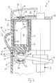
- eine Schnittdarstellung durch eine erfindungsgemäße Axialkolbenmaschine,
- Fig. 2
- eine Darstellung wie in
Figur 1 , jedoch bei einem anders ausgebildeten Kalottenlager, - Fig. 3-5
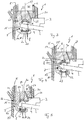
- jeweils Detaildarstellungen unterschiedlicher Kalottenlager,
- Fig.6
- eine Darstellung wie
Fig. 1 , jedoch ein kleinerer Ausschnitt und bei einem nochmal anders ausgebildeten Kalottenlager, - Fig. 7
- eine Detaildarstellung eines weiteren Kalottenlagers,
- Fig. 8
- eine Detaildarstellung einer Aufnahme oder Aufnahmeschale mit einem darin liegenden Gleitstein, und
- Fig. 9-12
- jeweils Detaildarstellungen unterschiedlicher Hohlkolben mit Kalottenlagern.
- Entsprechend den
Figuren 1 und2 weist eine erfindungsgemäße Axialkolbenmaschine 1, welche beispielsweise Bestandteil eines nicht näher gezeigten Wärmerückgewinnungssystems 2 eines Kraftfahrzeuges sein kann, eine Welle 3 auf, welche drehfest mit einer Schrägscheibe 4 verbunden ist. Um die Welle 3 herum und koaxial zu dieser angeordnet sind mehrere, vorzugsweise zumindest vier, Zylinder 5, in welchen gebaute und hohle Kolben 6 translatorisch verstellbar angeordnet sind. Jeder dieser Kolben 6 ist dabei über ein Kalottenlager 7 und einen Gleitstein 8 mit der Schrägscheibe 4 zum Antrieb der Welle 3 gekoppelt. Jedem Zylinder 5 ist darüber hinaus eine Einlassöffnung 9 zugeordnet, die je von einer Steuerscheibe 10 abdeckbar ist. Diese Steuerscheibe 10 besitzt eine exzentrisch angeordnete Durchgangsöffnung 11 und ist zudem drehfest mit der Welle 3 verbunden. Bei jeder Umdrehung der Steuerscheibe 10 überstreicht deren Durchgangsöffnung 11 jeweils einmal jede Einlassöffnung 9 eines Zylinders 5 und ermöglicht dadurch einen Zutritt von Arbeitsmedium in den zugehörigen Zylinder 5. Das Arbeitsmedium wird dabei zuvor in einem Sammelraum 12 unter Druck gesammelt, wobei dieser Sammelraum 12 beispielsweise mit einem Kreislauf eines Wärmerückgewinnungssystems 2 verbunden ist. Die Einlassöffnung 9 ist dabei in einer Zylinderabdeckung 13 angeordnet und fluchtet in genau einer Drehstellung der Steuerscheibe 10 mit deren Durchgangsöffnung 11. Zwischen der Zylinderabdeckung 13 und der Steuerscheibe 10 ist eine Dichtung 14 angeordnet, welche den Hohlraum 12 gegenüber dem Zylinder 5 abdichtet. - Erfindungsgemäß ist nun das Kalottenlager 7 mehrteilig, d.h. zumindest aus zwei Komponenten, zusammengesetzt, wodurch dessen Herstellbarkeit deutlich vereinfacht werden kann. Betrachtet man beispielsweise das Kalottenlager 7 gemäß der
Figur 1 , so kann man erkennen, dass dieses zweiteilig ausgeführt ist, mit einem ersten Teil 15 und einem zweiten Teil 16, wobei die beiden Teile 15, 16 jeweils eine Aufnahme 17 (vgl.Figur 1 ) oder eine Aufnahmeschale 18 (vgl.Figuren 2 bis 5 ) aufweisen. Der zweite Teil 16 des Kalottenlagers 7 kann dabei in kostengünstiger Weise als umgeformte Blechbrücke ausgebildet sein, wodurch insbesondere die Herstellung des Kalottenlagers 7 kostengünstiger und einfacher möglich ist. Durch die mehrteilige, insbesondere zweiteilige, Ausbildung des Kalottenlagers 7 können insbesondere die Aufnahmen 17 bzw. die Aufnahmeschalen 18 leichter nachbearbeitet bzw. überhaupt bearbeitet werden, wodurch nicht nur eine höhere Qualität, sondern auch eine einfachere Fertigung möglich ist. Vorzugsweise ist das zweite Teil 16, insbesondere die umgeformte Blechbrücke, mit dem ersten Teil 15 des Kalottenlagers 7 durch einen Presssitz, Schweißen, Löten und/oder thermisches Fügen verbunden. - Zumindest eine der Aufnahmen 17 bzw. der Aufnahmeschalen 18 kann darüber hinaus eine Beschichtung, insbesondere eine Polymerbeschichtung, eine DLC-Beschichtung oder eine Polytetrafluorethylenbeschichtung (PTFE) aufweisen oder aber nitriert sein. Diese nicht abschließende Aufzählung zeigt eine lokale verschleiß- und/oder reibungsreduzierende Beschichtung, welche insbesondere den Betrieb der Axialkolbenmaschine 1 erleichtert und deren Lebensdauer erhöht. Die Aufnahmeschalen 18 können beispielsweise aus Kunststoff, insbesondere als Kunststoffspritzgussteil ausgebildet sein, oder aber auch in zumindest eine zugehörige Aufnahme 17 des Kalottenlagers 7 eingespritzt werden. Prinzipiell bestehen dabei zwei unterschiedliche Herstellungsmethoden des Kalottenlagers 7, wobei bei der einen eine separate Aufnahmeschale 18 in dem jeweiligen Teil 15, 16 des Kalottenlagers 7 eingesetzt wird. Die anderen Methode sieht dagegen eine Aufnahme 17 im jeweiligen Teil 15, 16 vor, wobei zusätzlich in diese Aufnahme 17 entweder eine verschleiß- und/oder reibungsreduzierende Beschichtung oder aber auch eine Aufnahmeschale 18 einspritzt werden kann.
- Betrachtet man die
Figuren 2 bis 5 , so kann man erkennen, dass das Kalottenlager 7 fest mit dem zugehörigen Kolben 6 verbunden ist, beispielsweise mit diesem verstemmt, verschweißt oder verlötet ist, und eine zur Kolbenachse 19 parallele Bohrung 20 aufweist, in welche die jeweilige Aufnahmeschale 18 eingesetzt ist. Hierbei kann die jeweilige Aufnahmeschale 18 beispielsweise einen Fortsatz 21 bzw. Nippel aufweisen, der in die Bohrung 20 formschlüssig eingreift. Selbstverständlich kann die Aufnahmeschale 18 generell formschlüssig in eine entsprechende Ausnehmung 22 am ersten oder zweiten Teil 15, 16 des Kalottenlagers 7 eingesetzt werden. Darüber hinaus, kann beispielsweise eine Schraube 23 (vgl.Figur 4 ) oder eine Feder 24 (vgl.Figur 5 ), insbesondere eine Tellerfeder, vorgesehen werden, welche zumindest eine Aufnahmeschale 18 insbesondere von der Gegendruckseite aus gegen den zugehörigen Gleitstein 8 vorspannt. Der Gleitstein 8 selbst kann ebenfalls aus Kunststoff, insbesondere aus einem Polymer mit Polytetrafluorethylen (PTFE), ausgebildet sein, und dadurch einerseits verschleißfest und andererseits reibungsarm ausgebildet werden. Selbstverständlich ist auch die Auswahl eines anderen Materials mit einer entsprechenden Beschichtung denkbar. - Wie beispielsweise in
Fig. 8 dargestellt ist, sind zumindest eine der Aufnahmen 17 und der Gleitstein 8 derart geformt, dass der Gleitstein 8 in einem ringförmigen Kontaktbereich 38 in Kontakt mit der Aufnahme 17 ist, entsprechend können bei einer Ausführung mit Aufnahmeschalen 18 zumindest eine der Aufnahmeschalen 18 und der Gleitstein 8 derart geformt sein, dass der Gleitstein 8 in einem ringförmigen Kontaktbereich 38 in Kontakt mit der Aufnahmeschale 18 ist. - Der Kontaktbereich 38 erstreckt sich ringförmig um die Kolbenachse 19 herum. Insbesondere verläuft der Kontaktbereich 38 koaxial zu der Kolbenachse 19. Dadurch reduzieren sich Drehmomente, die durch den Gleitstein 8 über das Kalottenlager 7 auf den Kolben 6 übertragen werden. Dadurch reduziert sich wiederum die Gefahr einen Verkantens des Kolbens 6 in dem Zylinder 5. Vorzugsweise liegt der Kontaktbereich 38 in einem Winkelbereich von 20° bis 70°, besonders bevorzugt von 25° bis 60° oder noch bevorzugter von 30° bis 57° zu der Kolbenachse 19. Der Winkelbereich bezieht sich dabei bei einem halbkugelförmigen Gleitstein 8 auf einen Winkel 42, gemessen an einem Kugelmittelpunkt 41 des Gleitsteins 8, zwischen der Kolbenachse 19 und einer Verbindungslinie 51 zwischen dem Kugelmittelpunkt 41 und dem Kontaktbereich 38.
- Einen solcher Kontaktbereich 38 kann insbesondere dadurch erzielt werden, dass die Aufnahme 17 oder die Aufnahmeschale 18 eine Innenkontur 43 aufweist, an der der Gleitstein 8 anliegt und die aus einer Innenseite einer um eine Kreisbahn 39 rotierenden Hohlkugel 40 gebildet ist, wobei der Mittelpunkt 44 der Kreisbahn 39 auf einer Kolbenachse 19 liegt und die Kreisbahn 39 in einer im Wesentlichen senkrecht zur Kolbenachse 19 liegenden Ebene liegt. Die Kreisbahn 39 weist einen kleinen Radius 45 auf, so dass die Innenkontur 43 nur leicht von einer Kugelform abweicht. Der Radius 46 der Hohlkugel 40 ist dabei etwas größer als der Radius 47 der Halbkugel des Gleitsteins 8.
- Betrachtet man nochmals die
Figuren 1 und2 , so kann man erkennen, dass zumindest ein Kolben 6 ein aus einem Rohr hergestelltes Kolbenhemd 25 aufweist, wobei der Kolben 6 insgesamt aus dem Kolbenhemd 25, einem Kolbenboden 26 und dem Kalottenlager 7 zusammengesetzt ist. Die einzelnen Komponenten 25, 26 und 7 können dabei thermisch miteinander gefügt, miteinander verstemmt, verklebt, verschweißt oder verlötet sein. - Das Kolbenhemd 25 und der Kolbenboden 26 können beispielsweise zusammen aus einem tiefgezogenen Napf gebildet sein. So können das Kolbenhemd 25 und der Kolbenboden 26 in einem Arbeitsschritt gebildet werden. Ein Fügen des Kolbenhemds 25 mit dem Kolbenboden 26 ist dann nicht notwendig. Alternativ oder ergänzend hierzu kann vorgesehen sein, dass das Kolbenhemd 25 aus einem gezogenem Rohr gebildet ist, das mittels Kalt-, Halbwarm-, oder Warmumformen umgeformt ist.
- Auch das Kolbenhemd 25 kann eine Beschichtung aufweisen, insbesondere eine Polymerbeschichtung, eine DLC-Beschichtung oder eine Polytetrafluorethylenbeschichtung (PTFE) oder aber nitriert sein und dadurch einerseits verschleißbeständig und andererseits reibungsarm ausgebildet werden.
- Darüber hinaus ist es denkbar, dass das Kolbenhemd 25 ballig oder konvex ausgebildet ist, wie es beispielsweise in
Fig. 9 dargestellt ist. Dadurch kann insbesondere ein Verklemmen des Kolbens 6 im Zylinder 5 zuverlässig vermieden werden. Alternativ kann das Kolbenhemd 25 auch konkav ausgebildet sein, wie es beispielsweise inFig. 10 dargestellt ist. Dadurch kann eine mögliche Aufweitung des Kolbens 6 durch das Fügen des Kolbenhemdes 25 mit dem Kalottenlager 7 vermindert werden. Es können auch konkave und konvexe Bereiche kombiniert werden, so dass sowohl ein Verklemmen des Kolbens 6 im Zylinder 5 als auch eine Aufweitung des Kolbens 6 beim Fügen vermieden werden kann. - Dazu kann das Kolbenhemd 25, wie beispielhaft in
Fig. 12 dargestellt, in axialer Richtung mindestens zwei Abschnitte aufweist, die sich durch einen Außendurchmesser und/oder durch einen Innendurchmesser unterscheiden. Alternativ oder ergänzend hierzu kann vorgesehen sein, dass das Kolbenhemd 25 in axialer Richtung zweiteilig aufgebaut ist und dass ein erstes Teil 52 und ein zweites Teil 54 mittels thermischem Fügen, Verkleben, Verschweißen oder Verlöten miteinander verbunden sind. Dadurch kann eine größere Flexibilität bei der Ausgestaltung des Kolbens 6 erzielt werden.Fig. 11 zeigt beispielsweise einen Kolben 6 mit drei Abschnitten, die sich jeweils durch den Innendurchmesser und/oder den Außendurchmesser unterscheiden. - Um eine Rotation bzw. ein Verdrehen des Kolbens 6 um seine Kolbenachse 19 zuverlässig verhindern zu können, kann darüber hinaus vorgesehen sein, dass der Kolben 6 eine unrunde Außenkontur und der Zylinder 5 eine komplementär dazu ausgebildete unrunde Innenkontur aufweist. Alternativ kann auch zumindest eine Verdrehsicherung 32 vorgesehen sein, die ein Verdrehen des Kolbens 6 um seine Kolbenachse 19 im Zylinder 5 verhindert. Dies ist insbesondere dann von Vorteil, sofern der Kolben 6 keine unrunde Außenkontur besitzt. Die Verdrehsicherung 32 kann beispielsweise eine Nut 33 sowie einen darin eingreifenden Stift 34 umfassen, wobei der Stift 34 der Kalottenlager 7 und die Nut 33 an einem Gehäuse 35 angeordnet sind, oder umgekehrt.
- Des Weiteren kann eine Verdrehsicherung 32 vorgesehen sein, die eine Nut 33 und eine darin eingreifende Passfeder 48 aufweist, wobei die Passfeder 48 an dem Kalottenlager 7 und die Nut 33 an dem Gehäuse 35 angeordnet ist, oder umgekehrt. Vorzugsweise ist die Nut 33 durch mindesten einen in dem Gehäuse 35 angeordneten Führungskranz 49 gebildet. Der Führungskranz 49 kann beispielsweise durch ein umgeformtes Blech gebildet sein. Vorzugsweise ist der Führungskranz 49 durch eine Rastverbindung 53 in dem Gehäuse gehalten ist. Alternativ oder ergänzend hierzu kann der Führungskranz 49 einen Kragen 50 aufweisen, mit welchem der Führungskranz 49 zwischen zwei Gehäuseteilen verklemmt ist.
- Im Zylinder 5 kann darüber hinaus eine Zylinderlaufbuchse 27 vorgesehen werden, welche ebenfalls beispielsweise eine entsprechende Beschichtung aufweist, die zum einen den Verschleißwiderstand erhöht und zum anderen die Reibung herabsetzt. Am Zylinder 5 bzw. an der Zylinderlaufbuchse 27 kann darüber hinaus eine Einführphase 28 vorgesehen werden, die ein Einführen des Kolbens 6 in den Zylinder 5 erleichtert. Dies bietet den großen Vorteil, dass eine derartige Einführphase nicht am Kolbenboden 26 vorgesehen werden muss.
- Betrachtet man nochmals die
Figuren 1 und2 , so kann man erkennen, dass am Kolbenboden 26 eine in die Einlassöffnung 9 zumindest teilweise eingreifende Nase 29 angeordnet ist, so dass noch Abgas zum Anströmen und Betätigen des Kolbens 6 durch die Einlassöffnung 9 gelangen kann, unnützer Totraum hingegen, welcher Wirkungsgrad kostet, ausgefüllt wird. Darüber hinaus kann zumindest ein Kalottenlager 7 eine Entlüftungsbohrung 30 aufweisen, welche einen Kolbeninnenraum 31 mit der Umgebung verbindet bzw. zumindest einen Druckausgleich mit der der Umgebung außerhalb des Kolbens 6 ermöglicht. - Generell kann die beschriebene Axialkolbenmaschine 1 Bestandteil eines Wärmerückgewinnungssystems 2 eines im Übrigen nicht gezeichneten Kraftfahrzeugs sein, wodurch der Wirkungsgrad des Kraftfahrzeugs deutlich erhöht werden kann, da die Energie bisher ungenutzt in die Umgebung abgelassener Verbrennungsabgase nunmehr zumindest teilweise nutzbar ist.
- Im Bereich des unteren Totpunkts des Kolbens 6 besitzt das Gehäuse 35 eine Auslassöffnung 36, durch welche das Arbeitsmedium/Abgas in einen Ringkanal 37 ausströmen kann. Dieser Ringkanal 37 kann die Axialkolbenmaschine 1 zumindest teilweise ringförmig umgeben.
Claims (13)
- Axialkolbenmaschine (1),- mit einer Welle (3), die drehfest mit einer Schrägscheibe (4) verbunden ist,- mit ringförmig um und koaxial zur Welle (3) angeordneten Zylindern (5), in welchen Kolben (6) translatorisch verstellbar angeordnet sind, wobei jeder Kolben (6) über ein Kalottenlager (7) und mindestens einen Gleitstein (8) mit der Schrägscheibe (4) gekoppelt ist,- wobei jedem Zylinder (5) eine Einlassöffnung (9) zugeordnet ist,- mit einer Steuerscheibe (10) mit einer exzentrisch angeordneten Durchgangsöffnung (11), die bei jeder Umdrehung der Steuerscheibe (10) jede Einlassöffnung (9) einmal überstreicht und dabei Arbeitsmedium in den zugehörigen Zylinder (5) leitet, wobei- zumindest ein Kalottenlager (7) mehrteilig ausgebildet ist,- das Kalottenlager (7) zweiteilig ausgeführt ist mit einem ersten und einem zweiten Teil (15,16), wobei die beiden Teile (15,16) jeweils eine Aufnahme (17) oder eine Aufnahmeschale (18) für einen Gleitstein (8) aufweisen oder- das Kalottenlager (7) zweiteilig ausgeführt ist mit einem ersten und einem zweiten Teil (15,16), wobei der erste Teil (15) mit dem Kolbenhemd (25) verbunden ist und der zweiten Teil (16) zwei Aufnahmen (17) oder zwei Aufnahmeschalen (18) für den Gleitstein (8) aufweist, und dadurch gekennzeichnet- dass der zweite Teil (16) des Kalottenlagers (7) als umgeformte Blechbrücke ausgebildet ist.
- Axialkolbenmaschine nach Anspruch 1,
dadurch gekennzeichnet,
dass die umgeformte Blechbrücke mit dem ersten Teil (15) des Kalottenlagers (7) durch einen Presssitz, Schweißen, Löten und/oder thermisches Fügen verbunden ist. - Axialkolbenmaschine nach Anspruch 1 oder 2,
dadurch gekennzeichnet,
dass zumindest eine Aufnahme (17) oder eine Aufnahmeschale (18) eine Beschichtung aufweist, insbesondere eine Polymerbeschichtung, eine DLC-Beschichtung oder eine Polytetrafluorethylenbeschichtung (PTFE) oder nitriert ist. - Axialkolbenmaschine nach einem der Ansprüche 1 bis 3,
dadurch gekennzeichnet,
dass zumindest eine Aufnahmeschale (18) aus Kunststoff ausgebildet ist. - Axialkolbenmaschine nach einem der Ansprüche 1 bis 4,
dadurch gekennzeichnet,
dass zumindest eine Aufnahmeschale (18) in eine zugehörige Aufnahme (17) des Kalottenlagers (7) eingespritzt ist. - Axialkolbenmaschine nach einem der Ansprüche 1 bis 5,
dadurch gekennzeichnet,
dass das Kalottenlager (7) fest mit dem zugehörigen Kolben (6) verbunden ist und eine zur Kolbenachse (19) parallele Bohrung (20) aufweist, in welche die jeweilige Aufnahmeschale (18) eingesetzt ist. - Axialkolbenmaschine nach einem der Ansprüche 1 bis 6,
dadurch gekennzeichnet,
dass zumindest eine Aufnahmeschale (18) mittels einer Schraube (23) oder einer Feder (24), insbesondere einer Tellerfeder, insbesondere von der Gegendruckseite aus, gegen den zugehörigen Gleitstein (8) vorgespannt ist. - Axialkolbenmaschine nach einem der Ansprüche 1 bis 7,
dadurch gekennzeichnet,
dass zumindest ein Gleitstein (8) aus Kunststoff, insbesondere aus einem Polymer mit Polytetrafluorethylen (PTFE), ausgebildet ist. - Axialkolbenmaschine nach einem der Ansprüche 1 bis 8,
dadurch gekennzeichnet,- dass zumindest eine der Aufnahmen (17) und der Gleitstein (8) derart geformt sind, dass der Gleitstein (8) in einem ringförmigen Kontaktbereich (38) in Kontakt mit der Aufnahme (17) ist, oder- dass zumindest eine der Aufnahmeschalen (18) und der Gleitstein (8) derart geformt sind, dass der Gleitstein (8) in einem ringförmigen Kontaktbereich (38) in Kontakt mit der Aufnahmeschale (18) ist. - Axialkolbenmaschine nach Anspruch 9,
dadurch gekennzeichnet,- dass der Gleitstein (8) halbkugelförmig ausgebildet ist,- dass der ringförmige Kontaktbereich (38) sich in einem Winkelbereich von 30° bis 57° zu einer Kolbenachse (19), bezogen auf einen Kugelmittelpunkt (41) des Gleitsteins (8), liegt. - Axialkolbenmaschine nach Anspruch 9 oder 10,
dadurch gekennzeichnet,
dass die Aufnahme (17) oder die Aufnahmeschale (18) eine Innenkontur (43) aufweist, die aus einer Innenseite einer um eine Kreisbahn (39) rotierenden Hohlkugel (40) gebildet ist, wobei ein Mittelpunkt (44) der Kreisbahn (39) auf einer Kolbenachse (19) liegt und die Kreisbahn (39) in einer im Wesentlichen senkrecht zur Kolbenachse (19) liegenden Ebene liegt. - Axialkolbenmaschine nach einem der Ansprüche 1 bis 11,
dadurch gekennzeichnet,
dass zumindest ein Kalottenlager (7) eine Entlüftungsbohrung (30) aufweist, welche einen Kolbeninnenraum (31) mit der Umgebung verbindet. - Wärmerückgewinnungssystem (2) in einem Kraftfahrzeug mit einer Axialkolbenmaschine (1) nach einem der Ansprüche 1 bis 12.
Applications Claiming Priority (2)
| Application Number | Priority Date | Filing Date | Title |
|---|---|---|---|
| DE102014209892.0A DE102014209892A1 (de) | 2014-05-23 | 2014-05-23 | Axialkolbenmaschine |
| PCT/EP2015/061149 WO2015177231A2 (de) | 2014-05-23 | 2015-05-20 | Axialkolbenmaschine |
Publications (2)
| Publication Number | Publication Date |
|---|---|
| EP3146208A2 EP3146208A2 (de) | 2017-03-29 |
| EP3146208B1 true EP3146208B1 (de) | 2018-08-29 |
Family
ID=53181300
Family Applications (1)
| Application Number | Title | Priority Date | Filing Date |
|---|---|---|---|
| EP15723031.9A Not-in-force EP3146208B1 (de) | 2014-05-23 | 2015-05-20 | Axialkolbenmaschine |
Country Status (3)
| Country | Link |
|---|---|
| EP (1) | EP3146208B1 (de) |
| DE (1) | DE102014209892A1 (de) |
| WO (1) | WO2015177231A2 (de) |
Families Citing this family (2)
| Publication number | Priority date | Publication date | Assignee | Title |
|---|---|---|---|---|
| DE102016213283A1 (de) * | 2016-07-20 | 2018-01-25 | Mahle International Gmbh | Kolben für eine Axialkolbenmaschine |
| DE102017105610A1 (de) | 2017-03-16 | 2018-09-20 | Volkswagen Aktiengesellschaft | Axialkolbenmotor und Kreisprozessvorrichtung |
Family Cites Families (26)
| Publication number | Priority date | Publication date | Assignee | Title |
|---|---|---|---|---|
| DE423486C (de) * | 1917-07-19 | 1926-01-05 | Anthony George Maldon Michell | Vorrichtung zur Erzeugung hin und her gehender Bewegung aus Drehbewegung und umgekehrt |
| GB863026A (en) * | 1956-05-04 | 1961-03-15 | Edward Athelstan Halford | Improved reciprocatory machines |
| DE1949611A1 (de) * | 1969-10-01 | 1971-04-08 | Linde Ag | Axialkolbenmaschine |
| JPH04179873A (ja) * | 1990-11-09 | 1992-06-26 | Toyota Autom Loom Works Ltd | 揺動斜板式可変容量圧縮機及び揺動斜板とピストンを係留するシューの加工方法 |
| JPH0658248A (ja) * | 1992-08-06 | 1994-03-01 | Toyota Autom Loom Works Ltd | 斜板式圧縮機における回転軸支持構造 |
| US5362154A (en) * | 1993-08-16 | 1994-11-08 | Bernard Wiesen | Pivoting slipper pad bearing and crosshead mechanism |
| DE19620701A1 (de) * | 1995-06-21 | 1997-01-09 | Elektra Beckum Ag | Axialkolbenpumpe, insbesondere für ein Wasser-Hochdruckreinigungsgerät und Verfahren zur Herstellung eines Pumpenkolbens |
| DE19527647A1 (de) * | 1995-07-28 | 1997-01-30 | Linde Ag | Axialkolbenmaschine |
| JPH1047231A (ja) * | 1996-08-02 | 1998-02-17 | Zexel Corp | 可変容量型圧縮機 |
| DE19706066A1 (de) * | 1997-02-17 | 1997-11-20 | Hans Dipl Ing Unger | Kompressor, insbesondere für die Drucklufterzeugung in Kraftfahrzeugen |
| DE19754593A1 (de) * | 1997-12-10 | 1999-07-01 | Kleinedler Peter | Niederhaltering für Axialkolbenmaschinen |
| DE19847159C2 (de) * | 1998-10-13 | 2001-12-06 | Hans Unger | Kompressor zur Erzeugung ölfreier Druckluft |
| WO2000029793A1 (de) * | 1998-11-18 | 2000-05-25 | FKW HANNOVER Forschungszentrum für Kältetechnik und Wärmepumpen GmbH | Kolbenverdichter |
| KR100302852B1 (ko) * | 1999-03-20 | 2001-10-29 | 신영주 | 압축기용 중공 피스톤 제조방법 |
| JP2001107850A (ja) * | 1999-10-12 | 2001-04-17 | Zexel Valeo Climate Control Corp | 斜板式冷媒圧縮機 |
| DE19954863A1 (de) * | 1999-11-15 | 2001-07-26 | Zexel Valeo Compressor Europe | Kolbenmaschine, insbesondere Verdichter |
| US6736049B2 (en) * | 2000-12-11 | 2004-05-18 | Gilson, Inc. | High pressure low volume pump |
| DE60214685T8 (de) * | 2001-03-06 | 2007-05-16 | Honda Giken Kogyo K.K. | Expansionsmaschine |
| JP4539205B2 (ja) * | 2003-08-21 | 2010-09-08 | 日産自動車株式会社 | 冷媒圧縮機 |
| ATE422028T1 (de) * | 2005-04-23 | 2009-02-15 | Ixetic Mac Gmbh | Axialkolbenmaschine |
| KR101333858B1 (ko) * | 2006-07-29 | 2013-11-27 | 익세틱 마크 게엠베하 | 피스톤을 환상 디스크에 연결하기 위한 장치 |
| US20120079936A1 (en) * | 2009-04-01 | 2012-04-05 | Purdue Research Foundation | Positive displacement machine piston with wavy surface form |
| DE102009019627A1 (de) * | 2009-04-30 | 2010-11-04 | Linde Material Handling Gmbh | Hydrostatische Verdrängermaschine |
| DE102010026360B4 (de) * | 2010-07-07 | 2020-12-03 | Schaeffler Technologies AG & Co. KG | Stößel mit einer Verdrehsicherung |
| DE102010036917A1 (de) | 2010-08-09 | 2012-02-09 | Amovis Gmbh | Axialkolbenmaschine |
| DE102010052508A1 (de) * | 2010-11-26 | 2012-05-31 | Daimler Ag | Abwärmenutzungsvorrichtung |
-
2014
- 2014-05-23 DE DE102014209892.0A patent/DE102014209892A1/de not_active Withdrawn
-
2015
- 2015-05-20 EP EP15723031.9A patent/EP3146208B1/de not_active Not-in-force
- 2015-05-20 WO PCT/EP2015/061149 patent/WO2015177231A2/de not_active Ceased
Also Published As
| Publication number | Publication date |
|---|---|
| EP3146208A2 (de) | 2017-03-29 |
| WO2015177231A2 (de) | 2015-11-26 |
| DE102014209892A1 (de) | 2015-11-26 |
| WO2015177231A3 (de) | 2016-03-24 |
Similar Documents
| Publication | Publication Date | Title |
|---|---|---|
| EP1573200B1 (de) | Axialkolbenmaschine | |
| DE69925976T2 (de) | Käfig für Kugellager | |
| EP2342441B1 (de) | Kühlkanalkolben einer brennkraftmaschine mit einem verschlusselement, das den kühlkanal verschliesst | |
| EP0953113B1 (de) | Hubkolbenkompressor | |
| EP1636475A1 (de) | Kolben für einen verbrennungsmotor | |
| WO2016142229A1 (de) | Axialkolbenmaschine | |
| DE202006014691U1 (de) | Gleitlageranordnung für eine Welle, sowie Welle und zugeordneter Motor | |
| DE10325914B4 (de) | Kolben für einen Verbrennungsmotor | |
| DE102012207951B4 (de) | Kolben einer Brennkraftmaschine | |
| DE102011051257A1 (de) | Axialkolbenmaschine | |
| WO2005024217A1 (de) | Kolben für einen verbrennungsmotor | |
| WO2015177231A2 (de) | Axialkolbenmaschine | |
| DE19528910A1 (de) | Taumelscheibenverdichter | |
| WO2007016891A1 (de) | Kolben für einen verbrennungsmotor sowie abdeckring für den kühlkanal eines solchen kolbens | |
| DE19900037A1 (de) | Kraftstoffeinspritzventil | |
| EP1944510A1 (de) | Kolbenmaschine mit schwenkbar gelagerter Zylinderhülse | |
| WO2014001256A1 (de) | Besondere anordnung einer kühlkanalverbindungsbohrung eines kühlkanales | |
| WO2005019631A1 (de) | Mehrteiliger kolben für einen verbrennungsmotor | |
| DE102010023297A1 (de) | Ölversorgung für eine exzentrisch gelagerte Kurbelwelle | |
| EP3947994B1 (de) | Verfahren zum zusammenbau eines kugellagers | |
| WO2008080445A1 (de) | Hydraulische kolbenmaschine | |
| DE102010046031A1 (de) | Kompressor mit Kupplungseinrichtung | |
| DE4312498C2 (de) | Förderpumpe | |
| DE102015009568A1 (de) | Brennkraftmaschine sowie Verfahren zum Betreiben einer Brennkraftmaschine | |
| EP3008318A1 (de) | Gleitschuh für einen kolben zum einsatz in brennkraftmaschinen |
Legal Events
| Date | Code | Title | Description |
|---|---|---|---|
| STAA | Information on the status of an ep patent application or granted ep patent |
Free format text: STATUS: THE INTERNATIONAL PUBLICATION HAS BEEN MADE |
|
| PUAI | Public reference made under article 153(3) epc to a published international application that has entered the european phase |
Free format text: ORIGINAL CODE: 0009012 |
|
| STAA | Information on the status of an ep patent application or granted ep patent |
Free format text: STATUS: REQUEST FOR EXAMINATION WAS MADE |
|
| 17P | Request for examination filed |
Effective date: 20161121 |
|
| AK | Designated contracting states |
Kind code of ref document: A2 Designated state(s): AL AT BE BG CH CY CZ DE DK EE ES FI FR GB GR HR HU IE IS IT LI LT LU LV MC MK MT NL NO PL PT RO RS SE SI SK SM TR |
|
| AX | Request for extension of the european patent |
Extension state: BA ME |
|
| RIN1 | Information on inventor provided before grant (corrected) |
Inventor name: SCHACHERER, ROLAND Inventor name: LEUTERT, MARKUS Inventor name: BEERENS, CHRISTOPH Inventor name: MUELLER, ROLF Inventor name: SCHNEIDER, FALK Inventor name: BAITINGER, GERT Inventor name: KREISIG, MICHAEL Inventor name: WIESKE, PETER Inventor name: REPGEN, BERTHOLD |
|
| RIN1 | Information on inventor provided before grant (corrected) |
Inventor name: BAITINGER, GERT Inventor name: SCHACHERER, ROLAND Inventor name: BEERENS, CHRISTOPH Inventor name: LEUTERT, MARKUS Inventor name: KREISIG, MICHAEL Inventor name: WIESKE, PETER Inventor name: REPGEN, BERTHOLD Inventor name: MUELLER, ROLF Inventor name: SCHNEIDER, FALK |
|
| DAV | Request for validation of the european patent (deleted) | ||
| DAX | Request for extension of the european patent (deleted) | ||
| GRAP | Despatch of communication of intention to grant a patent |
Free format text: ORIGINAL CODE: EPIDOSNIGR1 |
|
| STAA | Information on the status of an ep patent application or granted ep patent |
Free format text: STATUS: GRANT OF PATENT IS INTENDED |
|
| INTG | Intention to grant announced |
Effective date: 20180507 |
|
| GRAS | Grant fee paid |
Free format text: ORIGINAL CODE: EPIDOSNIGR3 |
|
| GRAA | (expected) grant |
Free format text: ORIGINAL CODE: 0009210 |
|
| STAA | Information on the status of an ep patent application or granted ep patent |
Free format text: STATUS: THE PATENT HAS BEEN GRANTED |
|
| AK | Designated contracting states |
Kind code of ref document: B1 Designated state(s): AL AT BE BG CH CY CZ DE DK EE ES FI FR GB GR HR HU IE IS IT LI LT LU LV MC MK MT NL NO PL PT RO RS SE SI SK SM TR |
|
| REG | Reference to a national code |
Ref country code: GB Ref legal event code: FG4D Free format text: NOT ENGLISH |
|
| REG | Reference to a national code |
Ref country code: CH Ref legal event code: EP |
|
| REG | Reference to a national code |
Ref country code: AT Ref legal event code: REF Ref document number: 1035440 Country of ref document: AT Kind code of ref document: T Effective date: 20180915 |
|
| REG | Reference to a national code |
Ref country code: IE Ref legal event code: FG4D Free format text: LANGUAGE OF EP DOCUMENT: GERMAN |
|
| REG | Reference to a national code |
Ref country code: DE Ref legal event code: R096 Ref document number: 502015005685 Country of ref document: DE |
|
| REG | Reference to a national code |
Ref country code: NL Ref legal event code: MP Effective date: 20180829 |
|
| REG | Reference to a national code |
Ref country code: LT Ref legal event code: MG4D |
|
| PG25 | Lapsed in a contracting state [announced via postgrant information from national office to epo] |
Ref country code: FI Free format text: LAPSE BECAUSE OF FAILURE TO SUBMIT A TRANSLATION OF THE DESCRIPTION OR TO PAY THE FEE WITHIN THE PRESCRIBED TIME-LIMIT Effective date: 20180829 Ref country code: RS Free format text: LAPSE BECAUSE OF FAILURE TO SUBMIT A TRANSLATION OF THE DESCRIPTION OR TO PAY THE FEE WITHIN THE PRESCRIBED TIME-LIMIT Effective date: 20180829 Ref country code: IS Free format text: LAPSE BECAUSE OF FAILURE TO SUBMIT A TRANSLATION OF THE DESCRIPTION OR TO PAY THE FEE WITHIN THE PRESCRIBED TIME-LIMIT Effective date: 20181229 Ref country code: NO Free format text: LAPSE BECAUSE OF FAILURE TO SUBMIT A TRANSLATION OF THE DESCRIPTION OR TO PAY THE FEE WITHIN THE PRESCRIBED TIME-LIMIT Effective date: 20181129 Ref country code: NL Free format text: LAPSE BECAUSE OF FAILURE TO SUBMIT A TRANSLATION OF THE DESCRIPTION OR TO PAY THE FEE WITHIN THE PRESCRIBED TIME-LIMIT Effective date: 20180829 Ref country code: BG Free format text: LAPSE BECAUSE OF FAILURE TO SUBMIT A TRANSLATION OF THE DESCRIPTION OR TO PAY THE FEE WITHIN THE PRESCRIBED TIME-LIMIT Effective date: 20181129 Ref country code: SE Free format text: LAPSE BECAUSE OF FAILURE TO SUBMIT A TRANSLATION OF THE DESCRIPTION OR TO PAY THE FEE WITHIN THE PRESCRIBED TIME-LIMIT Effective date: 20180829 Ref country code: GR Free format text: LAPSE BECAUSE OF FAILURE TO SUBMIT A TRANSLATION OF THE DESCRIPTION OR TO PAY THE FEE WITHIN THE PRESCRIBED TIME-LIMIT Effective date: 20181130 Ref country code: LT Free format text: LAPSE BECAUSE OF FAILURE TO SUBMIT A TRANSLATION OF THE DESCRIPTION OR TO PAY THE FEE WITHIN THE PRESCRIBED TIME-LIMIT Effective date: 20180829 |
|
| PG25 | Lapsed in a contracting state [announced via postgrant information from national office to epo] |
Ref country code: AL Free format text: LAPSE BECAUSE OF FAILURE TO SUBMIT A TRANSLATION OF THE DESCRIPTION OR TO PAY THE FEE WITHIN THE PRESCRIBED TIME-LIMIT Effective date: 20180829 Ref country code: LV Free format text: LAPSE BECAUSE OF FAILURE TO SUBMIT A TRANSLATION OF THE DESCRIPTION OR TO PAY THE FEE WITHIN THE PRESCRIBED TIME-LIMIT Effective date: 20180829 Ref country code: HR Free format text: LAPSE BECAUSE OF FAILURE TO SUBMIT A TRANSLATION OF THE DESCRIPTION OR TO PAY THE FEE WITHIN THE PRESCRIBED TIME-LIMIT Effective date: 20180829 |
|
| PG25 | Lapsed in a contracting state [announced via postgrant information from national office to epo] |
Ref country code: ES Free format text: LAPSE BECAUSE OF FAILURE TO SUBMIT A TRANSLATION OF THE DESCRIPTION OR TO PAY THE FEE WITHIN THE PRESCRIBED TIME-LIMIT Effective date: 20180829 Ref country code: PL Free format text: LAPSE BECAUSE OF FAILURE TO SUBMIT A TRANSLATION OF THE DESCRIPTION OR TO PAY THE FEE WITHIN THE PRESCRIBED TIME-LIMIT Effective date: 20180829 Ref country code: RO Free format text: LAPSE BECAUSE OF FAILURE TO SUBMIT A TRANSLATION OF THE DESCRIPTION OR TO PAY THE FEE WITHIN THE PRESCRIBED TIME-LIMIT Effective date: 20180829 Ref country code: CZ Free format text: LAPSE BECAUSE OF FAILURE TO SUBMIT A TRANSLATION OF THE DESCRIPTION OR TO PAY THE FEE WITHIN THE PRESCRIBED TIME-LIMIT Effective date: 20180829 Ref country code: IT Free format text: LAPSE BECAUSE OF FAILURE TO SUBMIT A TRANSLATION OF THE DESCRIPTION OR TO PAY THE FEE WITHIN THE PRESCRIBED TIME-LIMIT Effective date: 20180829 Ref country code: EE Free format text: LAPSE BECAUSE OF FAILURE TO SUBMIT A TRANSLATION OF THE DESCRIPTION OR TO PAY THE FEE WITHIN THE PRESCRIBED TIME-LIMIT Effective date: 20180829 |
|
| PG25 | Lapsed in a contracting state [announced via postgrant information from national office to epo] |
Ref country code: DK Free format text: LAPSE BECAUSE OF FAILURE TO SUBMIT A TRANSLATION OF THE DESCRIPTION OR TO PAY THE FEE WITHIN THE PRESCRIBED TIME-LIMIT Effective date: 20180829 Ref country code: SM Free format text: LAPSE BECAUSE OF FAILURE TO SUBMIT A TRANSLATION OF THE DESCRIPTION OR TO PAY THE FEE WITHIN THE PRESCRIBED TIME-LIMIT Effective date: 20180829 Ref country code: SK Free format text: LAPSE BECAUSE OF FAILURE TO SUBMIT A TRANSLATION OF THE DESCRIPTION OR TO PAY THE FEE WITHIN THE PRESCRIBED TIME-LIMIT Effective date: 20180829 |
|
| REG | Reference to a national code |
Ref country code: DE Ref legal event code: R097 Ref document number: 502015005685 Country of ref document: DE |
|
| PLBE | No opposition filed within time limit |
Free format text: ORIGINAL CODE: 0009261 |
|
| STAA | Information on the status of an ep patent application or granted ep patent |
Free format text: STATUS: NO OPPOSITION FILED WITHIN TIME LIMIT |
|
| 26N | No opposition filed |
Effective date: 20190531 |
|
| PG25 | Lapsed in a contracting state [announced via postgrant information from national office to epo] |
Ref country code: SI Free format text: LAPSE BECAUSE OF FAILURE TO SUBMIT A TRANSLATION OF THE DESCRIPTION OR TO PAY THE FEE WITHIN THE PRESCRIBED TIME-LIMIT Effective date: 20180829 |
|
| REG | Reference to a national code |
Ref country code: CH Ref legal event code: PL |
|
| GBPC | Gb: european patent ceased through non-payment of renewal fee |
Effective date: 20190520 |
|
| PG25 | Lapsed in a contracting state [announced via postgrant information from national office to epo] |
Ref country code: MC Free format text: LAPSE BECAUSE OF FAILURE TO SUBMIT A TRANSLATION OF THE DESCRIPTION OR TO PAY THE FEE WITHIN THE PRESCRIBED TIME-LIMIT Effective date: 20180829 Ref country code: CH Free format text: LAPSE BECAUSE OF NON-PAYMENT OF DUE FEES Effective date: 20190531 Ref country code: LI Free format text: LAPSE BECAUSE OF NON-PAYMENT OF DUE FEES Effective date: 20190531 |
|
| REG | Reference to a national code |
Ref country code: BE Ref legal event code: MM Effective date: 20190531 |
|
| PG25 | Lapsed in a contracting state [announced via postgrant information from national office to epo] |
Ref country code: LU Free format text: LAPSE BECAUSE OF NON-PAYMENT OF DUE FEES Effective date: 20190520 |
|
| PG25 | Lapsed in a contracting state [announced via postgrant information from national office to epo] |
Ref country code: TR Free format text: LAPSE BECAUSE OF FAILURE TO SUBMIT A TRANSLATION OF THE DESCRIPTION OR TO PAY THE FEE WITHIN THE PRESCRIBED TIME-LIMIT Effective date: 20180829 |
|
| PG25 | Lapsed in a contracting state [announced via postgrant information from national office to epo] |
Ref country code: IE Free format text: LAPSE BECAUSE OF NON-PAYMENT OF DUE FEES Effective date: 20190520 Ref country code: GB Free format text: LAPSE BECAUSE OF NON-PAYMENT OF DUE FEES Effective date: 20190520 |
|
| PG25 | Lapsed in a contracting state [announced via postgrant information from national office to epo] |
Ref country code: BE Free format text: LAPSE BECAUSE OF NON-PAYMENT OF DUE FEES Effective date: 20190531 |
|
| PG25 | Lapsed in a contracting state [announced via postgrant information from national office to epo] |
Ref country code: FR Free format text: LAPSE BECAUSE OF NON-PAYMENT OF DUE FEES Effective date: 20190531 Ref country code: PT Free format text: LAPSE BECAUSE OF FAILURE TO SUBMIT A TRANSLATION OF THE DESCRIPTION OR TO PAY THE FEE WITHIN THE PRESCRIBED TIME-LIMIT Effective date: 20181229 |
|
| PG25 | Lapsed in a contracting state [announced via postgrant information from national office to epo] |
Ref country code: CY Free format text: LAPSE BECAUSE OF FAILURE TO SUBMIT A TRANSLATION OF THE DESCRIPTION OR TO PAY THE FEE WITHIN THE PRESCRIBED TIME-LIMIT Effective date: 20180829 |
|
| REG | Reference to a national code |
Ref country code: AT Ref legal event code: MM01 Ref document number: 1035440 Country of ref document: AT Kind code of ref document: T Effective date: 20200520 |
|
| PG25 | Lapsed in a contracting state [announced via postgrant information from national office to epo] |
Ref country code: HU Free format text: LAPSE BECAUSE OF FAILURE TO SUBMIT A TRANSLATION OF THE DESCRIPTION OR TO PAY THE FEE WITHIN THE PRESCRIBED TIME-LIMIT; INVALID AB INITIO Effective date: 20150520 Ref country code: MT Free format text: LAPSE BECAUSE OF FAILURE TO SUBMIT A TRANSLATION OF THE DESCRIPTION OR TO PAY THE FEE WITHIN THE PRESCRIBED TIME-LIMIT Effective date: 20180829 |
|
| PGFP | Annual fee paid to national office [announced via postgrant information from national office to epo] |
Ref country code: DE Payment date: 20210527 Year of fee payment: 7 |
|
| PG25 | Lapsed in a contracting state [announced via postgrant information from national office to epo] |
Ref country code: AT Free format text: LAPSE BECAUSE OF NON-PAYMENT OF DUE FEES Effective date: 20200520 |
|
| PG25 | Lapsed in a contracting state [announced via postgrant information from national office to epo] |
Ref country code: MK Free format text: LAPSE BECAUSE OF FAILURE TO SUBMIT A TRANSLATION OF THE DESCRIPTION OR TO PAY THE FEE WITHIN THE PRESCRIBED TIME-LIMIT Effective date: 20180829 |
|
| REG | Reference to a national code |
Ref country code: DE Ref legal event code: R119 Ref document number: 502015005685 Country of ref document: DE |
|
| PG25 | Lapsed in a contracting state [announced via postgrant information from national office to epo] |
Ref country code: DE Free format text: LAPSE BECAUSE OF NON-PAYMENT OF DUE FEES Effective date: 20221201 |