EP3141677A1 - Handhabe zum antrieb eines treibstangenbeschlages - Google Patents
Handhabe zum antrieb eines treibstangenbeschlages Download PDFInfo
- Publication number
- EP3141677A1 EP3141677A1 EP16184197.8A EP16184197A EP3141677A1 EP 3141677 A1 EP3141677 A1 EP 3141677A1 EP 16184197 A EP16184197 A EP 16184197A EP 3141677 A1 EP3141677 A1 EP 3141677A1
- Authority
- EP
- European Patent Office
- Prior art keywords
- handle
- sleeve
- handle according
- wing
- plug
- Prior art date
- Legal status (The legal status is an assumption and is not a legal conclusion. Google has not performed a legal analysis and makes no representation as to the accuracy of the status listed.)
- Granted
Links
- 230000008878 coupling Effects 0.000 claims description 2
- 238000010168 coupling process Methods 0.000 claims description 2
- 238000005859 coupling reaction Methods 0.000 claims description 2
- 230000000149 penetrating effect Effects 0.000 description 2
- 238000010276 construction Methods 0.000 description 1
- 210000004907 gland Anatomy 0.000 description 1
- 230000000977 initiatory effect Effects 0.000 description 1
- 230000036316 preload Effects 0.000 description 1
- 238000010008 shearing Methods 0.000 description 1
Images


Classifications
-
- E—FIXED CONSTRUCTIONS
- E05—LOCKS; KEYS; WINDOW OR DOOR FITTINGS; SAFES
- E05B—LOCKS; ACCESSORIES THEREFOR; HANDCUFFS
- E05B3/00—Fastening knobs or handles to lock or latch parts
-
- E—FIXED CONSTRUCTIONS
- E05—LOCKS; KEYS; WINDOW OR DOOR FITTINGS; SAFES
- E05C—BOLTS OR FASTENING DEVICES FOR WINGS, SPECIALLY FOR DOORS OR WINDOWS
- E05C9/00—Arrangements of simultaneously actuated bolts or other securing devices at well-separated positions on the same wing
- E05C9/02—Arrangements of simultaneously actuated bolts or other securing devices at well-separated positions on the same wing with one sliding bar for fastening when moved in one direction and unfastening when moved in opposite direction; with two sliding bars moved in the same direction when fastening or unfastening
- E05C9/021—Arrangements of simultaneously actuated bolts or other securing devices at well-separated positions on the same wing with one sliding bar for fastening when moved in one direction and unfastening when moved in opposite direction; with two sliding bars moved in the same direction when fastening or unfastening with rack and pinion mechanism
-
- E—FIXED CONSTRUCTIONS
- E05—LOCKS; KEYS; WINDOW OR DOOR FITTINGS; SAFES
- E05B—LOCKS; ACCESSORIES THEREFOR; HANDCUFFS
- E05B3/00—Fastening knobs or handles to lock or latch parts
- E05B3/04—Fastening the knob or the handle shank to the spindle by screws, springs or snap bolts
Definitions
- the invention relates to a handle for driving an espagnolette fitting of a wing pivotable against a frame with a plug, with a drive mandrel, wherein the drive mandrel has a first end portion for non-rotatable coupling with a nut of a drive gear of the espagnolette fitting and a second, non-rotatably coupled to the handle end portion with a drive mandrel between the two end portions enclosing sleeve, with a non-rotatably and axially immovable connectable to the sleeve holding part, wherein the holding part for screwing with the wing provided zigbohronne has, with an axially immovably held in the sleeve ring member and a securing element for Holder of the ring element on the drive mandrel.
- Such a handle is for example from the DE 296 16 292 U1 known.
- the drive mandrel penetrates the drive gear of the espagnolette fitting.
- a transversely in the drive mandrel arranged and resiliently biased pin engages behind the drive gear and secures the handle in the axial direction.
- tolerances of the wing can lead to a distortion of the drive pin in the drive gear. If the drive pin is too long, the handle also has a game, which is very disturbing in the operation of the handle.
- a handle has become known in which the plug-in handle is mounted in a retaining flange.
- the retaining flange is screwed from the side of the plug handle with the wing.
- this gland and the retaining flange are very disturbing.
- the invention is based on the problem to design a handle of the type mentioned so that it reliably avoids the initiation of a tension in the drive gear even with tolerances of the wing.
- the sleeve has in its lateral surface a radial feed slot for the introduction of the ring element.
- the handle can be used in arbitrarily designed drive gears and wings.
- the wing requires only a single bore for passing the sleeve with the drive mandrel.
- the drive mandrel requires only the appropriate length for use in various drive gears. Thanks to the invention, the handle can be easily preassembled to a complete unit, so that the final assembly on the wing designed by the mounting of the holding part is particularly simple.
- a fixing plug is arranged and if the fixing plug has a detachable at first actuation center fixing of the ring member.
- the handle can be preassembled with the fixing plug, wherein the center position of the drive pin is fixed by the fixing plug. Only at first actuation of the espagnolette fitting the connection of the fixing plug is released with the inner ring and the plug-in handle is freely rotatable to drive the drive gear.
- a shearing of projections by the center fixation can be according to another advantageous embodiment of the invention easily avoid when the ring member or the fixing plug has a ramp facing the opposing member and when the fixing plug is held axially displaceable and non-positively in the feed slot by the stroke of the ramp.
- the fixing plug is simply pushed a little way away from the ring element during the first actuation of the drive rod fitting, so that subsequently the ring element is freely rotatable relative to the fixing plug held in the sleeve.
- the handle is supported according to another advantageous embodiment of the invention particularly tip over on the outside of the wing, when the sleeve has on its side facing the handle a protruding flange for support on the wing.
- the handle can be easily mounted on the wing according to an advantageous embodiment of the invention, when the holding part radially engages over the sleeve at a distance from the flange. Due to the distance of the holding part of the flange, the sleeve can be seen from the plug handle from behind a wing flap of the wing connected to the wing. As a result, a screw connection of the handle with the wing in the closed state is not visible.
- the handle can be used according to another advantageous embodiment of the invention for any desired outer contours of the wing, when a voltage applied to the outside of the wing contour element supports the flange.
- the handle is structurally particularly simple according to another advantageous embodiment of the invention, when the sleeve is made in one piece with the contour element.
- the handle can be put together according to another advantageous embodiment of the invention for different wings from a particularly large number of identical parts, when the contour element is formed as a sleeve enclosing insert.
- the insert can be easily adjusted for the respective wing. Therefore, the sleeve and the handle for differently shaped wings can be made equal.
- a construction effort for a latching of the plug in positions provided can be kept particularly low according to another advantageous embodiment of the invention, when a latching device is arranged between the plug-in handle and the sleeve.
- the mounting of the plug handle designed according to another advantageous embodiment of the invention without play when the latching device is biased by a spring element against the sleeve and that the ring member is rotatably mounted in the sleeve and forms a bearing for the drive mandrel.
- the bias of the spring element allows the same time the preload of the bearing in the axial direction.
- the structural complexity for axial fixation of the sleeve on the drive mandrel can be kept particularly low according to another advantageous embodiment of the invention, when the ring member and the drive mandrel have aligned recesses for holding the securing element.
- one of the recesses may be formed as a bore and the securing element as a simple press pin.
- the disassembly of the drive pin with the handle element is particularly simple according to another advantageous embodiment of the invention, when a recess in the holding member is aligned with the recess in the ring member. As a result, the securing element is easily accessible through the recess in the holding part for disassembly.
- FIG. 1 The handle 1 can be pivoted against a frame, not shown, and lock in this above the espagnolette 3.
- FIG. 2 shows in a sectional view along the line II - II FIG. 1
- the handle 2 has a trained as a square drive pin 6, which is inserted with a first end portion 7 in the drive gear 5 and a second end portion 8 in the plug handle 4 rotationally fixed and axially immovable is pressed.
- a sleeve 9 with a flange 10 is mounted on the wing 1.
- the flange 10 is made in the illustrated embodiment in one piece with a contour element 11 which is supported on the plug handle 4 facing side of the wing 1.
- the sleeve 9 On the side facing away from the plug-in handle 4, the sleeve 9 has a ring element 12.
- the ring element 12 is held axially immovably in the sleeve 9 in a feed slot 13 and kept non-rotatable and axially immovable on the drive pin 6 by means of a securing element 14 designed as a press-fit pin.
- the feed slot 13 is closed by a fixing plug 15.
- a screwed to the wing 1 holding part 16 connects the sleeve 9 to the wing 1.
- the holding part 16 is spaced from the contour element 11 and seen from the plug handle 4 from behind a wing flap 17 of the wing 1.
- the handle 2 is screwed in the so-called folding side with the wing 1.
- a biased by a spring element 18 latching device 19 is arranged between the plug-in handle 4 and the sleeve 9 .
- the latching device 19 allows a tangible engagement of the plug-in handle 4 in the intended rotational positions relative to the sleeve 9.
- the spring element 18 biases the latching device 19 against the sleeve 9, which in turn on the ring element 12 is supported. Since the ring member 12 forms an axial bearing for the sleeve 9 on the drive mandrel 6, the bias by the spring element 18 prevents tilting of the plug handle 4th
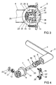
- FIG. 3 shows in a sectional view through the handle 2 FIG. 2 along the line III - III, that the ring element 12, the drive pin 6 and the holding part 16 have aligned recesses 20, 21 for the securing element 14.
- the Fixierstopfen 15 has a penetrating into the ring member 12 projection 23 with at least one ramp 24. Furthermore, the fixing plug 15 is frictionally held in the feed slot 13.
- the projection 23 forms a central fixing 25, which is released during the first actuation of the handle 2. By the ramp 24 of the fixing plug 15 is pushed out with the projection 23 from the range of movement of the ring member 12. Further shows FIG. 2 in that the holding part 16 has a projection 26 penetrating into the sleeve 9.
- FIG. 4 shows for clarity an exploded view of the components of the handle 2 before assembly. It can be seen that the holding part 16 has an arrow mark 27 for the correct orientation on the wing 1. The holding part 16 has screw holes for passing fastening screws 28 for screwing in the wing 1.
Landscapes
- Engineering & Computer Science (AREA)
- Mechanical Engineering (AREA)
- Mechanically-Actuated Valves (AREA)
- Lock And Its Accessories (AREA)
Abstract
Description
- Die Erfindung betrifft eine Handhabe zum Antrieb eines Treibstangenbeschlages eines gegen einen Rahmen schwenkbaren Flügels mit einem Steckgriff, mit einem Antriebsdorn, wobei der Antriebsdorn einen ersten Endabschnitt zur drehfesten Koppelung mit einer Nuss eines Antriebsgetriebes des Treibstangenbeschlages und einen zweiten, mit dem Steckgriff drehfest gekoppelten Endabschnitt hat, mit einer den Antriebsdorn zwischen den beiden Endabschnitten umschließenden Hülse, mit einem drehfest und axial unverschieblich mit der Hülse verbindbaren Halteteil, wobei das Halteteil zur Verschraubung mit dem Flügel vorgesehene Schraubbohrungen hat, mit einem axial unverschieblich in der Hülse gehaltenen Ringelement und mit einem Sicherungselement zur Halterung des Ringelements auf dem Antriebsdorn.
- Eine solche Handhabe ist beispielsweise aus der
DE 296 16 292 U1 bekannt. Bei dieser Handhabe durchdringt der Antriebsdorn das Antriebsgetriebe des Treibstangenbeschlages. Ein quer in dem Antriebsdorn angeordneter und federelastisch vorgespannter Pin hintergreift das Antriebsgetriebe und sichert den Steckgriff in axialer Richtung. Nachteilig bei dieser Handhabe ist jedoch, dass Toleranzen des Flügels zu einer Verspannung des Antriebsdorns in dem Antriebsgetriebe führen können. Ist der Antriebsdorn zu lang, hat der Steckgriff zudem ein Spiel, was bei der Bedienung der Handhabe sehr störend ist. - Weiterhin ist aus der
DE 103 07 503 A1 eine Handhabe bekannt geworden, bei dem der Steckgriff in einem Halteflansch gelagert ist. Der Halteflansch wird von der Seite des Steckgriffs mit dem Flügel verschraubt. Diese Verschraubung und der Halteflansch sind jedoch sehr störend. - Der Erfindung liegt das Problem zugrunde, eine Handhabe der eingangs genannten Art so zu gestalten, dass sie auch bei Toleranzen des Flügels die Einleitung einer Verspannung in das Antriebsgetriebe zuverlässig vermeidet.
- Dieses Problem wird erfindungsgemäß dadurch gelöst, dass die Hülse in ihrer Mantelfläche einen radialen Zuführschlitz zur Einführung des Ringelementes hat.
- Durch diese Gestaltung ist ein Hintergreifen des Antriebsgetriebes zur Fixierung des Antriebsdorns nicht erforderlich. Der Antriebsdorn wird durch das in dem Zuführschlitz gehaltene Ringelement axial in der Hülse gehalten. Da die Hülse über das Halteteil mit dem Flügel verschraubbar ist, ist der Antriebsdorn im am Flügel montierten Zustand zwischen dem Steckgriff und dem Antriebsgetriebe drehbar und axial unverschieblich gehalten. Die Einleitung von Spannungen in das Antriebsgetriebe wird dank der Erfindung vermieden. Ein weiterer Vorteil dieser Gestaltung besteht darin, dass die Handhabe bei beliebig gestalteten Antriebsgetrieben und Flügeln eingesetzt werden kann. Der Flügel benötigt nur eine einzige Bohrung zur Durchführung der Hülse mit dem Antriebsdorn. Der Antriebsdorn benötigt für den Einsatz in verschiedenen Antriebsgetrieben nur die entsprechende Länge. Dank der Erfindung lässt sich die Handhabe einfach zu einer kompletten Einheit vormontieren, so dass sich die Endmontage am Flügel durch die Montage des Halteteils besonders einfach gestaltet.
- Zur weiteren Vereinfachung der Montage der Handhabe trägt es gemäß einer anderen vorteilhaften Weiterbildung der Erfindung bei, wenn in dem Zuführschlitz ein Fixierstopfen angeordnet ist und wenn der Fixierstopfen eine bei Erstbetätigung lösbare Mittenfixierung des Ringelements hat. Durch diese Gestaltung lässt sich die Handhabe mit dem Fixierstopfen vormontieren, wobei die Mittelstellung des Antriebsdorns von dem Fixierstopfen festgelegt ist. Erst bei Erstbetätigung des Treibstangenbeschlages wird die Verbindung des Fixierstopfens mit dem Innenring gelöst und der Steckgriff ist zum Antrieb des Antriebsgetriebes frei drehbar.
- Ein Abscheren von Vorsprüngen durch die Mittenfixierung lässt sich gemäß einer anderen vorteilhaften Weiterbildung der Erfindung einfach vermeiden, wenn das Ringelement oder der Fixierstopfen eine dem gegenüberstehenden Bauteil zugewandte Rampe hat und wenn der Fixierstopfen um den Hubweg der Rampe axial verschieblich und kraftschlüssig in dem Zuführschlitz gehalten ist. Durch diese Gestaltung wird der Fixierstopfen bei der Erstbetätigung des Treibstangenbeschlages einfach ein Stück weit von dem Ringelement weggedrückt, so dass anschließend das Ringelement gegenüber dem in der Hülse gehaltenen Fixierstopfen frei drehbar ist.
- Die Handhabe ist gemäß einer anderen vorteilhaften Weiterbildung der Erfindung besonders kippsicher an der Außenseite des Flügels abgestützt, wenn die Hülse auf ihrer dem Steckgriff zugewandten Seite einen hervorstehenden Flansch zur Abstützung auf dem Flügel hat.
- Die Handhabe lässt sich gemäß einer vorteilhaften Weiterbildung der Erfindung einfach an dem Flügel montieren, wenn das Halteteil die Hülse mit Abstand zu dem Flansch radial übergreift. Durch den Abstand des Halteteils von dem Flansch kann die Hülse von dem Steckgriff aus gesehen hinter einem Flügelüberschlag des Flügels mit dem Flügel verbunden werden. Hierdurch ist eine Verschraubung der Handhabe mit dem Flügel im geschlossenen Zustand nicht sichtbar.
- Die Handhabe ist gemäß einer anderen vorteilhaften Weiterbildung der Erfindung für beliebig gestaltete Außenkonturen des Flügels einsetzbar, wenn ein auf der Außenseite des Flügels anliegendes Konturelement den Flansch abstützt.
- Die Handhabe gestaltet sich gemäß einer anderen vorteilhaften Weiterbildung der Erfindung konstruktiv besonders einfach, wenn die Hülse einstückig mit dem Konturelement gefertigt ist.
- Die Handhabe lässt sich gemäß einer anderen vorteilhaften Weiterbildung der Erfindung für verschiedene Flügel aus besonders vielen Gleichteilen zusammenstellen, wenn das Konturelement als die Hülse umschließendes Einlegeteil ausgebildet ist. Das Einlegeteil lässt sich einfach für den jeweiligen Flügel anpassen. Daher können die Hülse und der Steckgriff für verschieden gestaltete Flügel gleich aufgebaut sein.
- Ein baulicher Aufwand für eine Verrasterung des Steckgriffs in vorgesehenen Positionen lässt sich gemäß einer anderen vorteilhaften Weiterbildung der Erfindung besonders gering halten, wenn zwischen dem Steckgriff und der Hülse eine Rasteinrichtung angeordnet ist.
- Die Lagerung des Steckgriffs gestaltet sich gemäß einer anderen vorteilhaften Weiterbildung der Erfindung spielfrei, wenn die Rasteinrichtung von einem Federelement gegen die Hülse vorgespannt ist und dass das Ringelement drehbar in der Hülse gelagert ist und ein Lager für den Antriebsdorn bildet. Die Vorspannung des Federelementes ermöglicht gleichzeitig die Vorspannung des Lagers in axialer Richtung.
- Der bauliche Aufwand zur axialen Fixierung der Hülse auf dem Antriebsdorn lässt sich gemäß einer anderen vorteilhaften Weiterbildung der Erfindung besonders gering halten, wenn das Ringelement und der Antriebsdorn fluchtende Ausnehmungen zur Halterung des Sicherungselementes aufweisen. Im konstruktiv einfachsten Fall kann eine der Ausnehmungen als Bohrung und das Sicherungselement als ein einfacher Pressstift ausgebildet sein.
- Die Demontage des Antriebsdorns mit dem Griffelement gestaltet sich gemäß einer anderen vorteilhaften Weiterbildung der Erfindung besonders einfach, wenn eine Ausnehmung in dem Halteteil mit der Ausnehmung in dem Ringelement fluchtet. Hierdurch ist das Sicherungselement durch die Ausnehmung im Halteteil zur Demontage einfach zugänglich.
- Die Erfindung lässt zahlreiche Ausführungsformen zu. Zur weiteren Verdeutlichung ihres Grundprinzips ist eine davon in der Zeichnung dargestellt und wird nachfolgend beschrieben. Diese zeigt in
- Fig. 1
- einen Teilbereich eines Flügels und eines Treibstangenbeschlages mit einer Handhabe
- Fig. 2
- vergrößert eine Schnittdarstellung durch die Handhabe aus
Figur 1 entlang der Linie II - II, - Fig. 3
- eine Schnittdarstellung durch die Handhabe aus
Figur 2 entlang der Linie III - III, - Fig. 4
- eine Explosionsdarstellung der Handhabe.
-
Figur 1 zeigt einen Teilbereich eines Flügels 1 mit einer Handhabe 2 zum Antrieb eines Treibstangenbeschlages 3. Die Handhabe 2 hat einen in dem Flügel 1 schwenkbar gelagerten Steckgriff 4. Der Flügel 1 lässt sich gegen einen nicht dargestellten Rahmen schwenken und in diesem über dem Treibstangenbeschlag 3 verriegeln. -
Figur 2 zeigt in einer Schnittdarstellung entlang der Linie II - II ausFigur 1 vergrößert einen Teilbereich der Handhabe 2 mit dem Flügel 1 und einem Antriebsgetriebe 5 des Treibstangenbeschlages 3. Die Handhabe 2 hat einen als Vierkant ausgebildeten Antriebsdorn 6, der mit einem ersten Endabschnitt 7 in das Antriebsgetriebe 5 eingeführt ist und mit einem zweiten Endabschnitt 8 in den Steckgriff 4 drehfest und axial unverschieblich eingepresst ist. Eine Hülse 9 mit einem Flansch 10 ist auf dem Flügel 1 befestigt. Der Flansch 10 ist bei der dargestellten Ausführungsform einstückig mit einem Konturelement 11 gefertigt, welches sich auf der dem Steckgriff 4 zugewandten Seite des Flügels 1 abstützt. Auf der dem Steckgriff 4 abgewandten Seite hat die Hülse 9 ein Ringelement 12. Das Ringelement 12 ist in einem Zuführschlitz 13 axial unverschieblich in der Hülse 9 gehalten und mittels eines als Pressspannstift ausgebildeten Sicherungselementes 14 auf dem Antriebsdorn 6 unverdrehbar und axial unverschieblich gehalten. Der Zuführschlitz 13 ist von einem Fixierstopfen 15 verschlossen. Ein mit dem Flügel 1 verschraubtes Halteteil 16 verbindet die Hülse 9 an dem Flügel 1. Das Halteteil 16 ist von dem Konturelement 11 beabstandet und von dem Steckgriff 4 aus gesehen hinter einem Flügelüberschlag 17 des Flügels 1 angeordnet. Damit ist die Handhabe 2 in der so genannten Falzseite mit dem Flügel 1 verschraubt. - Zwischen dem Steckgriff 4 und der Hülse 9 ist eine von einem Federelement 18 vorgespannte Rasteinrichtung 19 angeordnet. Die Rasteinrichtung 19 ermöglicht ein fühlbares Einrasten des Steckgriffs 4 in vorgesehenen Drehstellungen gegenüber der Hülse 9. Das Federelement 18 spannt die Rasteinrichtung 19 gegen die Hülse 9 vor, welche sich wiederum an dem Ringelement 12 abstützt. Da das Ringelement 12 eine Axiallagerung für die Hülse 9 an dem Antriebsdorn 6 bildet, verhindert die Vorspannung durch das Federelement 18 ein Kippeln des Steckgriffs 4.
-
Figur 3 zeigt in einer Schnittdarstellung durch die Handhabe 2 ausFigur 2 entlang der Linie III - III, dass das Ringelement 12, der Antriebsdorn 6 und das Halteteil 16 fluchtende Ausnehmungen 20, 21 für das Sicherungselement 14 haben. Der Fixierstopfen 15 hat einen in das Ringelement 12 eindringenden Vorsprung 23 mit zumindest einer Rampe 24. Weiterhin ist der Fixierstopfen 15 kraftschlüssig in dem Zuführschlitz 13 gehalten. Der Vorsprung 23 bildet eine Mittenfixierung 25, welche bei der Erstbetätigung der Handhabe 2 gelöst wird. Durch die Rampe 24 wird der Fixierstopfen 15 mit dem Vorsprung 23 aus dem Bewegungsbereich des Ringelements 12 herausgedrückt. Weiterhin zeigtFigur 2 , dass das Halteteil 16 einen in die Hülse 9 eindringenden Vorsprung 26 hat. -
Figur 4 zeigt zur Verdeutlichung eine Explosionsdarstellung der Bauteile der Handhabe 2 vor der Montage. Hierbei ist zu erkennen, dass das Halteteil 16 eine Pfeilmarkierung 27 zur lagerichtigen Ausrichtung an dem Flügel 1 hat. Das Halteteil 16 hat Schraubbohrungen zur Durchführung von Befestigungsschrauben 28 zur Verschraubung in dem Flügel 1.
Claims (12)
- Handhabe (2) zum Antrieb eines Treibstangenbeschlages (3) eines gegen einen Rahmen schwenkbaren Flügels (1) mit einem Steckgriff (4), mit einem Antriebsdorn (6), wobei der Antriebsdorn (6) einen ersten Endabschnitt (7) zur drehfesten Koppelung mit einer Nuss eines Antriebsgetriebes (5) des Treibstangenbeschlages (3) und einen zweiten, mit dem Steckgriff (4) drehfest gekoppelten Endabschnitt (8) hat, mit einer den Antriebsdorn (6) zwischen den beiden Endabschnitten (7, 8) umschließenden Hülse (9), mit einem drehfest und axial unverschieblich mit der Hülse (9) verbindbaren Halteteil (16), wobei das Halteteil (16) zur Verschraubung mit dem Flügel (1) vorgesehene Schraubbohrungen hat, mit einem axial unverschieblich in der Hülse (9) gehaltenen Ringelement (12) und mit einem Sicherungselement (14) zur Halterung des Ringelements (12) auf dem Antriebsdorn (6), dadurch gekennzeichnet, dass die Hülse (9) in ihrer Mantelfläche einen radialen Zuführschlitz (13) zur Einführung des Ringelementes (12) hat.
- Handhabe nach Anspruch 1, dadurch gekennzeichnet, dass in dem Zuführschlitz (13) ein Fixierstopfen (15) angeordnet ist und dass der Fixierstopfen (15) eine bei Erstbetätigung lösbare Mittenfixierung (25) des Ringelements (12) hat.
- Handhabe nach Anspruch 2, dadurch gekennzeichnet, dass das Ringelement (12) oder der Fixierstopfen (15) eine dem gegenüberstehenden Bauteil zugewandte Rampe (24) hat und dass der Fixierstopfen (15) um den Hubweg der Rampe (24) axial verschieblich und kraftschlüssig in dem Zuführschlitz (13) gehalten ist.
- Handhabe nach einem der Ansprüche 1 bis 3, dadurch gekennzeichnet, dass die Hülse (9) auf ihrer dem Steckgriff (4) zugewandten Seite einen hervorstehenden Flansch (10) zur Abstützung auf dem Flügel (1) hat
- Handhabe nach Anspruch 4, dadurch gekennzeichnet, dass das Halteteil (16) die Hülse (9) mit Abstand zu dem Flansch (10) radial übergreift.
- Handhabe nach Anspruch 4 oder 5, dadurch gekennzeichnet, dass ein auf der Außenseite des Flügels anliegendes Konturelement (11) den Flansch (10) abstützt.
- Handhabe nach Anspruch 6, dadurch gekennzeichnet, dass die Hülse (9) einstückig mit dem Konturelement (11) gefertigt ist.
- Handhabe nach Anspruch 6, dadurch gekennzeichnet, dass das Konturelement (11) als die Hülse (9) umschließendes Einlegeteil ausgebildet ist.
- Handhabe nach einem der vorhergehenden Ansprüche, dadurch gekennzeichnet, dass zwischen dem Steckgriff (4) und der Hülse (9) eine Rasteinrichtung (19) angeordnet ist.
- Handhabe nach Anspruch 9, dadurch gekennzeichnet, dass die Rasteinrichtung (19) von einem Federelement (18) gegen die Hülse (9) vorgespannt ist und dass das Ringelement (12) drehbar in der Hülse (9) gelagert ist und ein Lager für den Antriebsdorn (6) bildet.
- Handhabe nach einem der vorhergehenden Ansprüche, dadurch gekennzeichnet, dass das Ringelement (12) und der Antriebsdorn (6) fluchtende Ausnehmungen (20, 21) zur Halterung des Sicherungselementes (14) aufweisen.
- Handhabe nach Anspruch 11, dadurch gekennzeichnet, dass eine Ausnehmung (22) in dem Halteteil (16) mit der Ausnehmung (21) in dem Ringelement (12) fluchtet.
Priority Applications (1)
| Application Number | Priority Date | Filing Date | Title |
|---|---|---|---|
| PL16184197T PL3141677T3 (pl) | 2015-09-14 | 2016-08-15 | Uchwyt do napędu okucia zasuwnicy |
Applications Claiming Priority (1)
| Application Number | Priority Date | Filing Date | Title |
|---|---|---|---|
| DE102015217540.5A DE102015217540A1 (de) | 2015-09-14 | 2015-09-14 | Handhabe zum Antrieb eines Treibstangenbeschlages |
Publications (2)
| Publication Number | Publication Date |
|---|---|
| EP3141677A1 true EP3141677A1 (de) | 2017-03-15 |
| EP3141677B1 EP3141677B1 (de) | 2018-05-23 |
Family
ID=56740104
Family Applications (1)
| Application Number | Title | Priority Date | Filing Date |
|---|---|---|---|
| EP16184197.8A Active EP3141677B1 (de) | 2015-09-14 | 2016-08-15 | Handhabe zum antrieb eines treibstangenbeschlages |
Country Status (4)
| Country | Link |
|---|---|
| EP (1) | EP3141677B1 (de) |
| DE (1) | DE102015217540A1 (de) |
| ES (1) | ES2673586T3 (de) |
| PL (1) | PL3141677T3 (de) |
Cited By (2)
| Publication number | Priority date | Publication date | Assignee | Title |
|---|---|---|---|---|
| IT201800004490A1 (it) * | 2018-04-13 | 2019-10-13 | Dispositivo di comando manuale di una serratura di una finestra | |
| IT201800004474A1 (it) * | 2018-04-13 | 2019-10-13 | Dispositivo di comando manuale di una serratura di una finestra |
Citations (5)
| Publication number | Priority date | Publication date | Assignee | Title |
|---|---|---|---|---|
| GB2276662A (en) * | 1993-03-31 | 1994-10-05 | Takigen Mfg Co | Lock handle assembly with detachable handle |
| DE29616292U1 (de) | 1996-09-19 | 1996-11-07 | Roto Frank Ag, 70771 Leinfelden-Echterdingen | Drehbetätigungseinrichtung |
| DE69618315T2 (de) * | 1995-10-26 | 2002-08-14 | Technal, Toulouse | Abnehmbarer Griff für Türen oder Fenster insbesondere in Metallprofilen |
| DE10307503A1 (de) | 2003-02-21 | 2004-09-02 | Aug. Winkhaus Gmbh & Co. Kg | Rastmodul für Fenster- und/oder Türbeschläge |
| DE102013000256A1 (de) * | 2013-01-09 | 2014-07-10 | Griffwerk GmbH | Befestigung fûr einen Drücker |
-
2015
- 2015-09-14 DE DE102015217540.5A patent/DE102015217540A1/de not_active Withdrawn
-
2016
- 2016-08-15 PL PL16184197T patent/PL3141677T3/pl unknown
- 2016-08-15 EP EP16184197.8A patent/EP3141677B1/de active Active
- 2016-08-15 ES ES16184197.8T patent/ES2673586T3/es active Active
Patent Citations (5)
| Publication number | Priority date | Publication date | Assignee | Title |
|---|---|---|---|---|
| GB2276662A (en) * | 1993-03-31 | 1994-10-05 | Takigen Mfg Co | Lock handle assembly with detachable handle |
| DE69618315T2 (de) * | 1995-10-26 | 2002-08-14 | Technal, Toulouse | Abnehmbarer Griff für Türen oder Fenster insbesondere in Metallprofilen |
| DE29616292U1 (de) | 1996-09-19 | 1996-11-07 | Roto Frank Ag, 70771 Leinfelden-Echterdingen | Drehbetätigungseinrichtung |
| DE10307503A1 (de) | 2003-02-21 | 2004-09-02 | Aug. Winkhaus Gmbh & Co. Kg | Rastmodul für Fenster- und/oder Türbeschläge |
| DE102013000256A1 (de) * | 2013-01-09 | 2014-07-10 | Griffwerk GmbH | Befestigung fûr einen Drücker |
Cited By (3)
| Publication number | Priority date | Publication date | Assignee | Title |
|---|---|---|---|---|
| IT201800004490A1 (it) * | 2018-04-13 | 2019-10-13 | Dispositivo di comando manuale di una serratura di una finestra | |
| IT201800004474A1 (it) * | 2018-04-13 | 2019-10-13 | Dispositivo di comando manuale di una serratura di una finestra | |
| WO2019197604A1 (en) * | 2018-04-13 | 2019-10-17 | Opentech S.R.L. A Socio Unico | Manual control device for manually controlling a lock of a window |
Also Published As
| Publication number | Publication date |
|---|---|
| EP3141677B1 (de) | 2018-05-23 |
| PL3141677T3 (pl) | 2018-10-31 |
| DE102015217540A1 (de) | 2017-03-16 |
| ES2673586T3 (es) | 2018-06-22 |
Similar Documents
| Publication | Publication Date | Title |
|---|---|---|
| EP1426633B1 (de) | Befestigungssystem | |
| DE102011102159B4 (de) | Modularer Schließzylinder | |
| EP2909399B1 (de) | System mit türbetätigungsteil und schliesszylinder | |
| EP1978187B1 (de) | Beschlaganordnung für ein Fenster, eine Tür oder dergleichen | |
| DE102009016755B4 (de) | Verfahren und Befestigungsvorrichtungen zum Befestigen eines Fahrzeugteils | |
| EP1722050B1 (de) | Drehriegelschloss | |
| EP3141677B1 (de) | Handhabe zum antrieb eines treibstangenbeschlages | |
| EP1724417B1 (de) | Schlosselement | |
| EP1683938B1 (de) | Verschluss für einen Treibstangenbeschlag | |
| EP3115294B1 (de) | Zug-druck-stange | |
| EP3119641B1 (de) | Verbindungsanordnung für ein gestänge eines fahrzeugsitzes und fahrzeugsitz | |
| EP3486407B1 (de) | Drückerelement und fenstergriffgarnitur | |
| EP1577465B1 (de) | Schlosselement mit Befestigung für Betätigungselement | |
| EP3115625A1 (de) | Zug-druck-stange mit verbindungsbolzen | |
| DE102016123468B3 (de) | Schnell-dreh-antriebswerkzeug | |
| EP2226572A2 (de) | Vorrichtung zum Haltern eines Heizkörpers | |
| EP3194690A1 (de) | Beschlag für fenster, türen und dergleichen und getriebeeinheit für einen solchen beschlag | |
| DE19904713C1 (de) | Vorrichtung zur axialen Festlegung eines Bolzens | |
| DE102019113666A1 (de) | Schließzylinder | |
| DE102013000256A1 (de) | Befestigung fûr einen Drücker | |
| DE102010061428A1 (de) | Einstellvorrichtung für Scheinwerfer | |
| EP2429868B1 (de) | Befestigungsanordnung | |
| EP3276107B1 (de) | Fenstergriffbeschlag | |
| DE19940728A1 (de) | Profilstift für Türdrücker | |
| DE202013101886U1 (de) | Schließvorrichtung, insbesondere Schließvorrichtung für eine Tür oder ein Fenster |
Legal Events
| Date | Code | Title | Description |
|---|---|---|---|
| PUAI | Public reference made under article 153(3) epc to a published international application that has entered the european phase |
Free format text: ORIGINAL CODE: 0009012 |
|
| AK | Designated contracting states |
Kind code of ref document: A1 Designated state(s): AL AT BE BG CH CY CZ DE DK EE ES FI FR GB GR HR HU IE IS IT LI LT LU LV MC MK MT NL NO PL PT RO RS SE SI SK SM TR |
|
| AX | Request for extension of the european patent |
Extension state: BA ME |
|
| 17P | Request for examination filed |
Effective date: 20170815 |
|
| RBV | Designated contracting states (corrected) |
Designated state(s): AL AT BE BG CH CY CZ DE DK EE ES FI FR GB GR HR HU IE IS IT LI LT LU LV MC MK MT NL NO PL PT RO RS SE SI SK SM TR |
|
| GRAP | Despatch of communication of intention to grant a patent |
Free format text: ORIGINAL CODE: EPIDOSNIGR1 |
|
| RIC1 | Information provided on ipc code assigned before grant |
Ipc: E05B 3/04 20060101ALN20171204BHEP Ipc: E05B 3/00 20060101AFI20171204BHEP Ipc: E05C 9/02 20060101ALI20171204BHEP |
|
| INTG | Intention to grant announced |
Effective date: 20180111 |
|
| GRAS | Grant fee paid |
Free format text: ORIGINAL CODE: EPIDOSNIGR3 |
|
| GRAA | (expected) grant |
Free format text: ORIGINAL CODE: 0009210 |
|
| AK | Designated contracting states |
Kind code of ref document: B1 Designated state(s): AL AT BE BG CH CY CZ DE DK EE ES FI FR GB GR HR HU IE IS IT LI LT LU LV MC MK MT NL NO PL PT RO RS SE SI SK SM TR |
|
| REG | Reference to a national code |
Ref country code: GB Ref legal event code: FG4D Free format text: NOT ENGLISH |
|
| REG | Reference to a national code |
Ref country code: CH Ref legal event code: EP |
|
| REG | Reference to a national code |
Ref country code: IE Ref legal event code: FG4D Free format text: LANGUAGE OF EP DOCUMENT: GERMAN |
|
| REG | Reference to a national code |
Ref country code: AT Ref legal event code: REF Ref document number: 1001637 Country of ref document: AT Kind code of ref document: T Effective date: 20180615 |
|
| REG | Reference to a national code |
Ref country code: ES Ref legal event code: FG2A Ref document number: 2673586 Country of ref document: ES Kind code of ref document: T3 Effective date: 20180622 |
|
| REG | Reference to a national code |
Ref country code: DE Ref legal event code: R096 Ref document number: 502016001095 Country of ref document: DE |
|
| REG | Reference to a national code |
Ref country code: NL Ref legal event code: MP Effective date: 20180523 |
|
| REG | Reference to a national code |
Ref country code: LT Ref legal event code: MG4D |
|
| PG25 | Lapsed in a contracting state [announced via postgrant information from national office to epo] |
Ref country code: SE Free format text: LAPSE BECAUSE OF FAILURE TO SUBMIT A TRANSLATION OF THE DESCRIPTION OR TO PAY THE FEE WITHIN THE PRESCRIBED TIME-LIMIT Effective date: 20180523 Ref country code: FI Free format text: LAPSE BECAUSE OF FAILURE TO SUBMIT A TRANSLATION OF THE DESCRIPTION OR TO PAY THE FEE WITHIN THE PRESCRIBED TIME-LIMIT Effective date: 20180523 Ref country code: BG Free format text: LAPSE BECAUSE OF FAILURE TO SUBMIT A TRANSLATION OF THE DESCRIPTION OR TO PAY THE FEE WITHIN THE PRESCRIBED TIME-LIMIT Effective date: 20180823 Ref country code: NO Free format text: LAPSE BECAUSE OF FAILURE TO SUBMIT A TRANSLATION OF THE DESCRIPTION OR TO PAY THE FEE WITHIN THE PRESCRIBED TIME-LIMIT Effective date: 20180823 Ref country code: LT Free format text: LAPSE BECAUSE OF FAILURE TO SUBMIT A TRANSLATION OF THE DESCRIPTION OR TO PAY THE FEE WITHIN THE PRESCRIBED TIME-LIMIT Effective date: 20180523 |
|
| PG25 | Lapsed in a contracting state [announced via postgrant information from national office to epo] |
Ref country code: GR Free format text: LAPSE BECAUSE OF FAILURE TO SUBMIT A TRANSLATION OF THE DESCRIPTION OR TO PAY THE FEE WITHIN THE PRESCRIBED TIME-LIMIT Effective date: 20180824 Ref country code: NL Free format text: LAPSE BECAUSE OF FAILURE TO SUBMIT A TRANSLATION OF THE DESCRIPTION OR TO PAY THE FEE WITHIN THE PRESCRIBED TIME-LIMIT Effective date: 20180523 Ref country code: HR Free format text: LAPSE BECAUSE OF FAILURE TO SUBMIT A TRANSLATION OF THE DESCRIPTION OR TO PAY THE FEE WITHIN THE PRESCRIBED TIME-LIMIT Effective date: 20180523 Ref country code: LV Free format text: LAPSE BECAUSE OF FAILURE TO SUBMIT A TRANSLATION OF THE DESCRIPTION OR TO PAY THE FEE WITHIN THE PRESCRIBED TIME-LIMIT Effective date: 20180523 Ref country code: RS Free format text: LAPSE BECAUSE OF FAILURE TO SUBMIT A TRANSLATION OF THE DESCRIPTION OR TO PAY THE FEE WITHIN THE PRESCRIBED TIME-LIMIT Effective date: 20180523 |
|
| PG25 | Lapsed in a contracting state [announced via postgrant information from national office to epo] |
Ref country code: RO Free format text: LAPSE BECAUSE OF FAILURE TO SUBMIT A TRANSLATION OF THE DESCRIPTION OR TO PAY THE FEE WITHIN THE PRESCRIBED TIME-LIMIT Effective date: 20180523 Ref country code: CZ Free format text: LAPSE BECAUSE OF FAILURE TO SUBMIT A TRANSLATION OF THE DESCRIPTION OR TO PAY THE FEE WITHIN THE PRESCRIBED TIME-LIMIT Effective date: 20180523 Ref country code: EE Free format text: LAPSE BECAUSE OF FAILURE TO SUBMIT A TRANSLATION OF THE DESCRIPTION OR TO PAY THE FEE WITHIN THE PRESCRIBED TIME-LIMIT Effective date: 20180523 Ref country code: DK Free format text: LAPSE BECAUSE OF FAILURE TO SUBMIT A TRANSLATION OF THE DESCRIPTION OR TO PAY THE FEE WITHIN THE PRESCRIBED TIME-LIMIT Effective date: 20180523 Ref country code: SK Free format text: LAPSE BECAUSE OF FAILURE TO SUBMIT A TRANSLATION OF THE DESCRIPTION OR TO PAY THE FEE WITHIN THE PRESCRIBED TIME-LIMIT Effective date: 20180523 |
|
| REG | Reference to a national code |
Ref country code: DE Ref legal event code: R097 Ref document number: 502016001095 Country of ref document: DE |
|
| PG25 | Lapsed in a contracting state [announced via postgrant information from national office to epo] |
Ref country code: SM Free format text: LAPSE BECAUSE OF FAILURE TO SUBMIT A TRANSLATION OF THE DESCRIPTION OR TO PAY THE FEE WITHIN THE PRESCRIBED TIME-LIMIT Effective date: 20180523 |
|
| PG25 | Lapsed in a contracting state [announced via postgrant information from national office to epo] |
Ref country code: MC Free format text: LAPSE BECAUSE OF FAILURE TO SUBMIT A TRANSLATION OF THE DESCRIPTION OR TO PAY THE FEE WITHIN THE PRESCRIBED TIME-LIMIT Effective date: 20180523 |
|
| PLBE | No opposition filed within time limit |
Free format text: ORIGINAL CODE: 0009261 |
|
| STAA | Information on the status of an ep patent application or granted ep patent |
Free format text: STATUS: NO OPPOSITION FILED WITHIN TIME LIMIT |
|
| PG25 | Lapsed in a contracting state [announced via postgrant information from national office to epo] |
Ref country code: LU Free format text: LAPSE BECAUSE OF NON-PAYMENT OF DUE FEES Effective date: 20180815 |
|
| 26N | No opposition filed |
Effective date: 20190226 |
|
| REG | Reference to a national code |
Ref country code: IE Ref legal event code: MM4A |
|
| PG25 | Lapsed in a contracting state [announced via postgrant information from national office to epo] |
Ref country code: SI Free format text: LAPSE BECAUSE OF FAILURE TO SUBMIT A TRANSLATION OF THE DESCRIPTION OR TO PAY THE FEE WITHIN THE PRESCRIBED TIME-LIMIT Effective date: 20180523 |
|
| PG25 | Lapsed in a contracting state [announced via postgrant information from national office to epo] |
Ref country code: IE Free format text: LAPSE BECAUSE OF NON-PAYMENT OF DUE FEES Effective date: 20180815 |
|
| PG25 | Lapsed in a contracting state [announced via postgrant information from national office to epo] |
Ref country code: FR Free format text: LAPSE BECAUSE OF NON-PAYMENT OF DUE FEES Effective date: 20180831 |
|
| PG25 | Lapsed in a contracting state [announced via postgrant information from national office to epo] |
Ref country code: AL Free format text: LAPSE BECAUSE OF FAILURE TO SUBMIT A TRANSLATION OF THE DESCRIPTION OR TO PAY THE FEE WITHIN THE PRESCRIBED TIME-LIMIT Effective date: 20180523 |
|
| PG25 | Lapsed in a contracting state [announced via postgrant information from national office to epo] |
Ref country code: MT Free format text: LAPSE BECAUSE OF FAILURE TO SUBMIT A TRANSLATION OF THE DESCRIPTION OR TO PAY THE FEE WITHIN THE PRESCRIBED TIME-LIMIT Effective date: 20180523 |
|
| PG25 | Lapsed in a contracting state [announced via postgrant information from national office to epo] |
Ref country code: TR Free format text: LAPSE BECAUSE OF FAILURE TO SUBMIT A TRANSLATION OF THE DESCRIPTION OR TO PAY THE FEE WITHIN THE PRESCRIBED TIME-LIMIT Effective date: 20180523 |
|
| PG25 | Lapsed in a contracting state [announced via postgrant information from national office to epo] |
Ref country code: PT Free format text: LAPSE BECAUSE OF FAILURE TO SUBMIT A TRANSLATION OF THE DESCRIPTION OR TO PAY THE FEE WITHIN THE PRESCRIBED TIME-LIMIT Effective date: 20180523 Ref country code: LI Free format text: LAPSE BECAUSE OF NON-PAYMENT OF DUE FEES Effective date: 20190831 Ref country code: CH Free format text: LAPSE BECAUSE OF NON-PAYMENT OF DUE FEES Effective date: 20190831 |
|
| PG25 | Lapsed in a contracting state [announced via postgrant information from national office to epo] |
Ref country code: CY Free format text: LAPSE BECAUSE OF FAILURE TO SUBMIT A TRANSLATION OF THE DESCRIPTION OR TO PAY THE FEE WITHIN THE PRESCRIBED TIME-LIMIT Effective date: 20180523 Ref country code: MK Free format text: LAPSE BECAUSE OF NON-PAYMENT OF DUE FEES Effective date: 20180523 Ref country code: HU Free format text: LAPSE BECAUSE OF FAILURE TO SUBMIT A TRANSLATION OF THE DESCRIPTION OR TO PAY THE FEE WITHIN THE PRESCRIBED TIME-LIMIT; INVALID AB INITIO Effective date: 20160815 |
|
| PG25 | Lapsed in a contracting state [announced via postgrant information from national office to epo] |
Ref country code: IS Free format text: LAPSE BECAUSE OF FAILURE TO SUBMIT A TRANSLATION OF THE DESCRIPTION OR TO PAY THE FEE WITHIN THE PRESCRIBED TIME-LIMIT Effective date: 20180923 |
|
| GBPC | Gb: european patent ceased through non-payment of renewal fee |
Effective date: 20200815 |
|
| PG25 | Lapsed in a contracting state [announced via postgrant information from national office to epo] |
Ref country code: GB Free format text: LAPSE BECAUSE OF NON-PAYMENT OF DUE FEES Effective date: 20200815 |
|
| P01 | Opt-out of the competence of the unified patent court (upc) registered |
Effective date: 20230515 |
|
| PGFP | Annual fee paid to national office [announced via postgrant information from national office to epo] |
Ref country code: IT Payment date: 20230831 Year of fee payment: 8 Ref country code: ES Payment date: 20230918 Year of fee payment: 8 Ref country code: AT Payment date: 20230818 Year of fee payment: 8 |
|
| PGFP | Annual fee paid to national office [announced via postgrant information from national office to epo] |
Ref country code: PL Payment date: 20230809 Year of fee payment: 8 |
|
| PGFP | Annual fee paid to national office [announced via postgrant information from national office to epo] |
Ref country code: DE Payment date: 20240819 Year of fee payment: 9 |
|
| PGFP | Annual fee paid to national office [announced via postgrant information from national office to epo] |
Ref country code: BE Payment date: 20240820 Year of fee payment: 9 |