EP3140202B1 - Füllnadel zum befüllen eines behälters mit einem fluid - Google Patents
Füllnadel zum befüllen eines behälters mit einem fluid Download PDFInfo
- Publication number
- EP3140202B1 EP3140202B1 EP15724531.7A EP15724531A EP3140202B1 EP 3140202 B1 EP3140202 B1 EP 3140202B1 EP 15724531 A EP15724531 A EP 15724531A EP 3140202 B1 EP3140202 B1 EP 3140202B1
- Authority
- EP
- European Patent Office
- Prior art keywords
- core
- actuating
- magnet
- filling needle
- housing
- Prior art date
- Legal status (The legal status is an assumption and is not a legal conclusion. Google has not performed a legal analysis and makes no representation as to the accuracy of the status listed.)
- Active
Links
Images


Classifications
-
- B—PERFORMING OPERATIONS; TRANSPORTING
- B65—CONVEYING; PACKING; STORING; HANDLING THIN OR FILAMENTARY MATERIAL
- B65B—MACHINES, APPARATUS OR DEVICES FOR, OR METHODS OF, PACKAGING ARTICLES OR MATERIALS; UNPACKING
- B65B3/00—Packaging plastic material, semiliquids, liquids or mixed solids and liquids, in individual containers or receptacles, e.g. bags, sacks, boxes, cartons, cans, or jars
- B65B3/04—Methods of, or means for, filling the material into the containers or receptacles
-
- A—HUMAN NECESSITIES
- A61—MEDICAL OR VETERINARY SCIENCE; HYGIENE
- A61J—CONTAINERS SPECIALLY ADAPTED FOR MEDICAL OR PHARMACEUTICAL PURPOSES; DEVICES OR METHODS SPECIALLY ADAPTED FOR BRINGING PHARMACEUTICAL PRODUCTS INTO PARTICULAR PHYSICAL OR ADMINISTERING FORMS; DEVICES FOR ADMINISTERING FOOD OR MEDICINES ORALLY; BABY COMFORTERS; DEVICES FOR RECEIVING SPITTLE
- A61J1/00—Containers specially adapted for medical or pharmaceutical purposes
- A61J1/14—Details; Accessories therefor
- A61J1/20—Arrangements for transferring or mixing fluids, e.g. from vial to syringe
- A61J1/2003—Accessories used in combination with means for transfer or mixing of fluids, e.g. for activating fluid flow, separating fluids, filtering fluid or venting
- A61J1/2006—Piercing means
- A61J1/201—Piercing means having one piercing end
-
- B—PERFORMING OPERATIONS; TRANSPORTING
- B65—CONVEYING; PACKING; STORING; HANDLING THIN OR FILAMENTARY MATERIAL
- B65B—MACHINES, APPARATUS OR DEVICES FOR, OR METHODS OF, PACKAGING ARTICLES OR MATERIALS; UNPACKING
- B65B3/00—Packaging plastic material, semiliquids, liquids or mixed solids and liquids, in individual containers or receptacles, e.g. bags, sacks, boxes, cartons, cans, or jars
- B65B3/003—Filling medical containers such as ampoules, vials, syringes or the like
-
- B—PERFORMING OPERATIONS; TRANSPORTING
- B65—CONVEYING; PACKING; STORING; HANDLING THIN OR FILAMENTARY MATERIAL
- B65B—MACHINES, APPARATUS OR DEVICES FOR, OR METHODS OF, PACKAGING ARTICLES OR MATERIALS; UNPACKING
- B65B3/00—Packaging plastic material, semiliquids, liquids or mixed solids and liquids, in individual containers or receptacles, e.g. bags, sacks, boxes, cartons, cans, or jars
- B65B3/26—Methods or devices for controlling the quantity of the material fed or filled
-
- B—PERFORMING OPERATIONS; TRANSPORTING
- B65—CONVEYING; PACKING; STORING; HANDLING THIN OR FILAMENTARY MATERIAL
- B65B—MACHINES, APPARATUS OR DEVICES FOR, OR METHODS OF, PACKAGING ARTICLES OR MATERIALS; UNPACKING
- B65B39/00—Nozzles, funnels or guides for introducing articles or materials into containers or wrappers
- B65B39/001—Nozzles, funnels or guides for introducing articles or materials into containers or wrappers with flow cut-off means, e.g. valves
- B65B39/004—Nozzles, funnels or guides for introducing articles or materials into containers or wrappers with flow cut-off means, e.g. valves moving linearly
-
- B—PERFORMING OPERATIONS; TRANSPORTING
- B65—CONVEYING; PACKING; STORING; HANDLING THIN OR FILAMENTARY MATERIAL
- B65B—MACHINES, APPARATUS OR DEVICES FOR, OR METHODS OF, PACKAGING ARTICLES OR MATERIALS; UNPACKING
- B65B39/00—Nozzles, funnels or guides for introducing articles or materials into containers or wrappers
- B65B39/12—Nozzles, funnels or guides for introducing articles or materials into containers or wrappers movable towards or away from container or wrapper during filling or depositing
-
- F—MECHANICAL ENGINEERING; LIGHTING; HEATING; WEAPONS; BLASTING
- F16—ENGINEERING ELEMENTS AND UNITS; GENERAL MEASURES FOR PRODUCING AND MAINTAINING EFFECTIVE FUNCTIONING OF MACHINES OR INSTALLATIONS; THERMAL INSULATION IN GENERAL
- F16K—VALVES; TAPS; COCKS; ACTUATING-FLOATS; DEVICES FOR VENTING OR AERATING
- F16K31/00—Actuating devices; Operating means; Releasing devices
- F16K31/02—Actuating devices; Operating means; Releasing devices electric; magnetic
- F16K31/06—Actuating devices; Operating means; Releasing devices electric; magnetic using a magnet, e.g. diaphragm valves, cutting off by means of a liquid
- F16K31/08—Actuating devices; Operating means; Releasing devices electric; magnetic using a magnet, e.g. diaphragm valves, cutting off by means of a liquid using a permanent magnet
- F16K31/086—Actuating devices; Operating means; Releasing devices electric; magnetic using a magnet, e.g. diaphragm valves, cutting off by means of a liquid using a permanent magnet the magnet being movable and actuating a second magnet connected to the closing element
Definitions
- the present invention relates to a filling needle for filling a container with a fluid, in particular a pharmaceutical or cosmetic fluid, with a housing, the housing extending along a longitudinal axis and having an inlet opening and an outlet opening, a core element which is parallel to the housing the longitudinal axis is arranged to be displaceable between an opening position and a closing position, a stamp element which is coupled to the core element, in particular connected to the core element and displaceable together with the core element, the stamp element closing the outlet opening in the closing position and releasing it in the opening position, and an actuating arrangement for displacing the core element between the open position and the closed position.
- Filling needles of this type are generally known in the prior art. They are used, for example, to fill fluids for pharmaceutical or cosmetic use in containers.
- the filling needles are first introduced through an opening into an interior of the container and preferably withdrawn successively from the container during the filling process in order to enable the container to be filled even through small openings and without spray losses.
- one or more filling needles can be provided in filling systems in order to fill a corresponding number of containers at the same time.
- the publication shows an example of a device and a method for filling containers DE 10 2006 019 518 A1 .
- an apparatus and a method for filling containers which has at least one filling device which supplies liquid to at least one container to be filled via a filling needle, the filling needle being used for completely filling the container.
- a drive device is to be provided which moves the filling needle during the filling process.
- the publication also shows, for example DE 42 27 980 A1 a device for metering a medium into a container from at least one nozzle or the like, which is connected via at least one line to a metering device which connects to a storage container. Depending on the activity of a conveying device, the nozzle should run with the container during metering.
- the publication also shows DE 92 07 051 U1 a device for filling liquids of higher viscosity in a storage container for the liquid, from which a line leads to a pump, which opens into a filler neck.
- a shut-off valve should be interposed in the line before the filler neck, the shut-off valve being a solenoid valve, the opening duration of which can be changed.
- the solenoid valve is to be actuated by an adjustable time relay.
- solenoid valves are thus proposed in order to operatively block or release lines.
- the solenoid valves are arranged consistently between a storage container and a filling device.
- Other such solenoid valves generally arranged in fluid circuits are shown, for example, in the publications DE 32 27 616 A1 and DD 15 98 41 A1 .
- the publication DE 690 25 466 T2 shows an aseptic filling valve with a valve seat which is arranged inside a pipe part, an inner movable part which is arranged in the pipe part and has a valve body, with an outer movable part which is arranged outside the pipe part and magnetically coupled to the inner movable part is.
- the publication also shows US 2006/261300 A1 a valve with a body within which a needle is movable, which can lie with a seal on a seat which is attached to the body.
- the publication also shows US 5,450,877 a valve having a tubular body made of a non-magnetic material, a seat carried by the tubular body around a closure member disposed within the tubular body and facing the seat, the closure member having a valve member associated with is connected to a drive ring, which is made of a magnetic material and extends substantially coaxially with the tubular body.
- the publication DE 197 16 980 A1 shows an automatic shut-off valve, the shut-off valve having two non-return valves, which are directed against each other, so that both flow directions remain blocked in the switched state.
- the publication also shows WO 92/08919 A1 a valve, in particular for high purity and / or safety requirements, with a valve housing, the interior of which encloses a guide and actuating member.
- the publication also shows DE 90 15 711 U1 a valve, in particular for high purity and / or safety requirements, with a valve housing, the interior of which, through which a liquid or gaseous medium can be passed, has an inlet channel and an outlet channel.
- JP 2001-012644 A a solenoid valve which is intended to perform the opening and closing operation of the valve body using the magnetism of a magnet.
- the publication also shows EP 1 985 900 A2 Valves for controlling the fluid flow and in particular a coaxial valve which is intended to dispense chemically aggressive fluids for the pharmaceutical or medical sector and also for use in the food industry.
- the filling needles have to be cleaned at certain intervals in order to be able to safely meet existing requirements for clean room conditions etc. To do this, the filling systems must be stopped and all filling needles removed and cleaned. Correspondingly, cleaning the filling needles is associated with a relatively high cost because the entire system has come to a standstill.
- nozzle needles for injecting fuel are known in which a magnet armature arrangement is moved by means of an optionally energized coil.
- this requires supplying such a nozzle needle with electrical current and may require more mechanically complex arrangements with spring assemblies that pretension the nozzle needle in a closed state in order to ensure safe operation.
- a filling needle for filling a container with a fluid, in particular a pharmaceutical or cosmetic fluid is therefore provided with a housing, the housing extending along a longitudinal axis and having an inlet opening and an outlet opening, a core element which is inside of the housing is displaceably arranged parallel to the longitudinal axis between an open position and a closed position, a stamp element which is coupled to the core element, the stamp element closing the outlet opening in the closed position and releasing it in the open position, and an actuating arrangement for moving the core element between the Open position and the closed position, wherein the core element has at least one core magnet designed as a permanent magnet, the actuating arrangement being arranged outside the housing and at least one en designed as a permanent magnet actuating magnet, and wherein the at least one core magnet and the at least one actuating magnet are arranged such that they interact attractively and the core element and the actuating arrangement can be moved together parallel to the longitudinal axis, the core element having an internal recess for
- the at least one actuating magnet and the at least one core magnet are arranged in such a way that they interact attractively. This means that a magnetic coupling of the core element to the actuation arrangement is provided.
- the field lines of the magnetic field formed by the actuating magnet and the core magnet act through the housing.
- the position of the longitudinal axis is always evident from the geometry of the filling needle.
- the filling needle always has an elongated section following the outlet opening, with which the filling needle is inserted into containers to be filled.
- the longitudinal axis of the filling needle runs correspondingly parallel to this longitudinal extent.
- the at least one core magnet is also provided in a ring, which results in a particularly strong interaction between the at least one core magnet and the at least one actuating magnet, in particular in cooperation with the alignment of the pole axes parallel to the longitudinal axis.
- the core element by pressing the inner element with the outer element.
- the at least one core magnet is then pressed in and held in the intermediate space formed between them. This can enable the core member to be fabricated without welding or other heat-affecting processes that may affect the magnetic properties of the at least one core magnet.
- a filling system with at least one filling needle according to the above-mentioned embodiment or one of its configurations is provided.
- Such a filling system can thus be serviced faster and more cost-effectively and provides essentially the same advantages.
- the actuation arrangement is of sleeve-shaped design, the sleeve-shaped actuation arrangement surrounding an axial section of the housing.
- the sleeve-shaped configuration of the actuation arrangement enables reliable guidance to be provided on the housing. At the same time, it enables the actuating magnets to be arranged directly on the housing in order to minimize losses in efficiency due to an air gap.
- the at least one actuating magnet is annular and surrounds the housing.
- the core element has a plurality of core magnets
- the actuation arrangement has a plurality of actuation magnets
- a number of the actuation magnets and a number of the core magnets are identical.
- both the core element and the actuation arrangement can extend over a longer axial section.
- a plurality of core magnets and a plurality of actuation magnets can consequently be provided.
- the identical number consequently means that a core magnet is assigned to a specific actuating magnet.
- the core element has a plurality of core ring elements, each core ring element being formed from at least one paramagnetic and / or ferromagnetic material, and wherein the plurality of core ring elements and the at least one core magnet are arranged alternately in the axial direction and that the actuation arrangement has a plurality of actuation ring elements, each actuation ring element being formed from at least one paramagnetic and / or ferromagnetic magnet, and wherein the plurality of actuation ring elements and the at least one actuation magnet are arranged alternately in the axial direction.
- the material for the at least one core magnet and / or the at least one actuating magnet can be iron or a ferrite such as iron oxide or another metal oxide. However, it is preferably a ferromagnetic material.
- the magnetic fields of the at least one core magnet of the at least one actuating magnet can be greatly strengthened.
- a particularly good magnetic coupling of the actuation arrangement and the core element can be provided by an alternating construction of magnets and ferromagnetic ring elements.
- paramagnetic Materials with a magnetic permeability greater than 1 are usually referred to as paramagnetic. Such materials are classified as ferromagnetic materials whose magnetic permeability is much greater than 1, since the magnetic moments of the ferromagnet are aligned parallel to an external magnetic field and strongly amplify it.
- ferrimagnetic and antiferromagnetic substances also have a magnetic order and can be used instead of a ferromagnetic material, in particular many oxides of ferromagnetic elements such as iron, nickel and cobalt. However, ferromagnetic materials are preferably used.
- the core element has an even number of core magnets and an odd number of core ring elements
- the actuating arrangement has an even number of actuating magnets and an odd number of actuating ring elements.
- the core ring elements or actuating ring elements are arranged "outside" or at the ends of the alternating sequence of ring elements and magnets.
- the magnetic field of the magnets can be strengthened in a particularly suitable manner and the axial installation space can be used effectively.
- the core element has two core magnets and three core ring elements, so that the actuation arrangement has two actuation magnets and three actuation ring elements.
- a pole axis of the at least one core magnet and a pole axis of the at least one actuating magnet are arranged parallel to the longitudinal axis of the housing, the polar axis of the at least one core magnet and the pole axis of the at least one actuating magnet being polarized in opposite directions .
- the ring-shaped configuration of the at least one actuating magnet enables an effective provision of a strong magnetic field if the polar axes are not aligned perpendicular to the longitudinal axis, but parallel to the longitudinal axis of the filling needle.
- the same can apply accordingly to the at least one core magnet. Due to the opposite polarity of an actuating magnet and an associated core magnet, the attractive forces required for magnetic coupling are provided.
- both the at least one core magnet and the at least one actuating magnet are annular and are arranged coaxially to one another, the axes of the strongest magnetic effects coincide with the longitudinal axis.
- the longitudinal axis then coincides with the rotational symmetry axes of the at least one core magnet and the at least one actuating magnet. Consequently, a particularly strong coupling is provided via the magnetic fields of the at least one actuating magnet and the at least one core magnet.
- the actuating arrangement has a first actuating magnet and a second actuating magnet, the pole axes of the actuating magnets running parallel to the longitudinal axis, and wherein the first actuating magnet and the second actuating magnet are poled in opposite directions, the core element being one has a first core magnet which is assigned to the first actuating magnet and is poled in opposite directions thereto, and wherein the core element has a second core magnet which is assigned to the second actuating magnet and is polarized in opposite directions thereto.
- a magnetically attractive arrangement can be provided overall, in which the first actuation magnet and the first core magnet as well as the second actuation magnet and the second core magnet together form a magnetic field in the manner of a quadrupole.
- a particularly effective coupling between the core element and the actuating element can be provided, in particular since the magnetic field lines between the first core magnet and the second core magnet or the first actuating magnet and the second actuating magnet run through the housing almost perpendicular to the longitudinal axis.
- the stamp element is a stamp element that closes the outlet opening on the inside or a stamp element that closes the outlet opening on the outside.
- the stamp element can thus be provided as a stamp element closing on the inside or outside.
- this Design only change the open position and the closed position. While in the case of the stamp element closing on the inside, a position of the core element close to the outlet opening forms the closed position and a position of the core element further away from the outlet opening forms an open position, this is exactly the opposite in the case of a stamp element closing on the outside.
- the actuation arrangement is driven pneumatically, hydraulically or electrically. It is preferably provided that the actuation arrangement is pneumatically driven, since pneumatics are generally provided anyway for operating a filling system, in particular for moving the entire filling needle into and out of a container, and thus a compressed air source is present. Basically, other types of drives can of course also be provided.
- the actuation arrangement is driven via a lever device.
- an actuator is articulated directly to the actuation arrangement or else is articulated to the actuation arrangement via a lever device.
- the force applied to the actuating arrangement for displacing it can be suitably adjusted via the lever device.
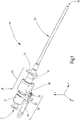
- Fig. 1 shows an embodiment of a filling needle 10.
- the filling needle 10 has a housing 12.
- the housing 12 extends between an inlet opening 14 and an outlet opening 16.
- the housing 12 has a first housing region 18 near the inlet opening.
- This first housing area 18 is also referred to as a filling tube.
- the housing 12 has a second housing region 20.
- the second housing area 20 can also be referred to as a needle housing.
- the first housing area 18 and the second housing area 20 are made in one piece.
- the housing 12 can, for example, also be made from two parts, in particular the first housing region 18 and the second housing region 20, in a separate embodiment.
- the first housing area 18 has an axial section 22. This axial section 22 of the first housing area 18 serves as a guide for an actuating arrangement 30 on its outer surface. On its inner surface, it serves as a guide for a core element described in detail below.
- a fastening flange 24 is arranged on the housing 12, the filling needle 10 can be mounted on a filling system, for example, via this fastening flange 24.
- the filling needle 10 has a pneumatic cylinder 26 in the illustrated embodiment.
- This is part of a drive device 28 which drives the actuating arrangement 30 parallel to a longitudinal extent of the filling needle (in the Fig. 1 the Y direction).
- other drive devices are also possible, for example a hydraulic drive device or an electrical drive device, which enable a translatory movement of the actuation arrangement 30 in the desired manner.
- a guide flange 25 is provided which supports the movement of the pneumatic cylinder 26 in the XZ plane. By activating the pneumatic cylinder 26 the actuating arrangement 30 can thus be displaced.
- the pneumatic cylinder 26 interlocks with a driving flange 32 provided on the actuation arrangement 30.
- the pneumatic cylinder 26 and the actuating arrangement 30 are coupled to one another in the Y direction. Actuation of the pneumatic cylinder 26 can then offset the actuation arrangement parallel to the Y direction.
- the actuation arrangement preferably has an aluminum housing.
- the actuating arrangement 30 is preferably guided via two plastic sliding bushes on an outer surface of the axial section 22.
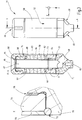
- the Fig. 2 shows a side view of the filling needle 10 in connection with the external environment of a filling system 36.
- the filling needle 10 serves to fill a fluid in a schematically illustrated container 34.
- the fluid is supplied from a reservoir 38 to the inlet opening 14 of the filling needle 10. This is done in the usual way.
- a control device 40 of the filling system 36 is used to control the filling needle 10, in particular a movement of the entire filling needle 10 parallel to the Y direction and an actuation of the pneumatic cylinder 26.
- a compressed air source 42 of the filling system can now be provided in order to provide the drive device 28 and to actuate the pneumatic cylinder 26 controlled by the control device 40.
- a longitudinal axis 43 of the filling needle 10 which runs along the longitudinal extent of the housing 12.
- the longitudinal axis 43 extends from the inlet opening 14 to the outlet opening 16.
- the housing 12 is hollow on the inside, so that a fluid can pass through the housing 12 from the inlet opening 14 to the outlet opening 16.
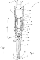
- the Fig. 3 shows a core element 44.
- the core element 44 is arranged in the interior of the housing 12, in particular within the first housing region 18.
- the core element 44 can be displaced parallel to the longitudinal axis 43 in the housing 12, ie parallel to the Y direction.
- the core element 44 has an inlet section 46, into which fluid that has entered the housing 12 through the inlet opening 14 enters the core element 44.
- it has at least one outlet section 48 through which the fluid leaves the core element 44 again in the direction of the outlet opening 16.
- the core element 44 has three outlet sections 48, two of which can be seen in the view shown.
- the outlet sections 48 are each offset by 120 °.
- the core element 44 thus essentially has the shape of a sleeve which surrounds the inner recess 47.
- the sleeve is identified by the reference number 50.
- the core element 44 can be displaceably guided in the housing 12 by means of an outer side of the sleeve 52.
- the core element 44 has an inner element 54 and an outer element 56. Each of the elements is substantially Z-shaped in the cross section of FIGS. 8-8.
- the inner element 54 and the outer element 56 are essentially rotationally symmetrical and sleeve-shaped. They form a space 57 between them.
- a first core magnet 58 and a second core magnet 60 can be arranged in this intermediate space 57.
- a total of three core ring elements 62, 64, 66 are arranged alternately with the first core magnet 58 and the second core magnet 60 in the Y direction, ie parallel to the longitudinal axis 43.
- spacer rings or spacers 80 can be provided in order to support the core magnets 58, 60 and the core ring elements 62, 64, 66 in the intermediate space 57. These can optionally be designed to be elastic in order to suitably support the core magnets 58, 60 and the core ring elements 62, 64, 66 during pressing of the inner element 54 and the outer element 56. By manufacturing the pressing, it is possible to produce the core element 44 in a suitable manner without impairing the core magnets 58, 60 due to excessively high temperatures.
- the core ring elements 62, 64, 66 are preferably formed from iron or another ferromagnetic material.
- Each of the core magnets 58, 60 and the core ring elements 62, 64, 66 are formed in a ring shape and enclose the inner recess 47. Furthermore, an upper end element 68 and a lower end element 70 are provided. The upper end element 68 is pressed with the outer element 56. Our final element 70 is pressed with the inner element 54. Sealing rings 72, 73, 74, 75 are arranged for, in particular pharmaceutically, sealing the inner recess 47 and thus the region into which the fluid is guided, in order to suitably seal the pressing surfaces. In the enlargement X, a corresponding fit 78 for pressing, for example, the lower end element 70 with the inner element 54 is indicated. The arrangement shown has the advantage that, for example, the sealing ring 72 can be used to seal both a surface between the inner element 54 and the outer element 56 and between the element 54 and the lower end element 70.
- the core element 44 in particular in the lower end element 70, has a stamp receptacle 82, via which it is connected to the stamp element (in FIG Fig. 3 not shown) can be connected.
- the stamp receptacle 82 is a thread receptacle into which the stamp element can be screwed.
- sliding bushes can also be provided on the core element in order to guide the core element.
- a sliding coating can also be applied in order to guide the core element 44 for the outside of the sleeve 52.
- the core magnets 58, 60 should not be heated above 200 ° C. in order not to impair their magnetic properties.
- the upper terminating element 68 and the lower terminating element 70 can be designed as sliding bushes.
- the upper closure element 68 and the lower closure element can be formed from polyether ether ketone (PEEK).
- the outer element 56 and the inner element 54 can also be formed from this material. This material is particularly advantageous in terms of its chemical resistance.
- the Fig. 4 shows a cross-sectional view taken along a line IV-IV in FIG Fig. 2 .
- the core element 44 is as in FIG Fig. 3 shown and performed in the axial section 22 of the housing 12.
- Actuating arrangement 30 has a first element 84 and a second element 86.
- the first element 84 essentially has a function like the outer element 56 of the core element 44.
- the inner element 86 essentially has a function like the inner element 54 of the core element 44. They can be pressed together and between them a first actuating magnet 88 and a second actuating magnet 90 record in the illustrated embodiment.
- three actuating ring elements 92, 94, 96 are provided in the illustrated embodiment.
- the actuating ring elements 92, 94, 96 are preferably made of iron or another ferromagnetic material.
- two sliding bushes 98 and 100 are provided, which guide the actuating arrangement 30 on the housing 12.
- a stamp element is denoted by 102 and screwed into the stamp receptacle 82 of the core element 44.
- the core element 54 is sealed on the stamp element 102 by means of a seal 103.
- the core element 44 and consequently the stamp element 102 is shown in an open position 104.
- a stamp head 108 of the stamp element 102 does not close the outlet opening 16 in this position.
- the actuating arrangement 30 is now driven by the drive device 28 in the positive Y direction, ie in the Fig. 4 moved downward, the core element is entrained in the positive Y direction due to the magnetic coupling between the core element 44 and the actuation arrangement 30. Consequently, the stamp element 102 also moves in the positive Y direction, so that the stamp head 108 closes the outlet opening 16 and the arrangement is then in a closed position 106.
- the stamp element 102 is shown as a stamp element closing on the inside.
- stamping elements closing on the outside are also conceivable. It then emerges that a closure position lies above, ie further in the negative Y direction, relative to the opening position, since a stamp head is then quasi drawn towards the outlet opening 16 must be to close them. Furthermore, the closed position 106 does not necessarily have to be arranged at the outlet opening 16 of the filling needle 10. In principle, other arrangements of the stamp element 102 between the reservoir 38 and the outlet opening 16 are also possible, in order to selectively block or release an outflow of the fluid due to the coupling of the stamp element 102 with the core element 44. In the Fig. 4 Another exemplary arrangement of a closed position 106 ′ on the housing 12 is designated.
- a closure position 106 ′′ can also be provided above or upstream of the core element 44.
- Fig. 5 shows a possibility for the arrangement of the core magnets 58, 60 and the actuating magnets 88, 90.
- the closing position 106 is shown on the left and the corresponding opening position 104 on the right.
- Negative poles S are marked with a "minus".
- Positive poles N are marked with a "plus”.
- a fluid 110 shown schematically with the aid of arrows, in particular a pharmaceutical or cosmetic fluid, enters the housing 12 through the inlet opening 14 and can flow through the inner recess 47. In the opening position 4 shown on the right, the fluid can thus exit the core element 44 through the internal recess 47 and the outlet sections 48 and ultimately reach the second housing region 70 in the direction of the outlet opening 16.
- the pole axes 112 of the actuating magnets 88, 90 are formed parallel to the Y axis, that is to say parallel to the longitudinal axis 43.
- the pole axes of the actuating magnets 88, 90 are designated 112.
- the pole axes of the core magnets 58, 60 are designated 114.
- the Pole axes 112, 114 are only indicated schematically.
- the pole axes 112, 114 could also be shown coaxially with the longitudinal axis 43.
- the poles of the first actuating magnet 88 and the second actuating magnet 90 are designed in opposite directions.
- the poles of the first core magnet 58 and the second core magnet 60 which are likewise designed in opposite directions.
- the first actuating magnet 88 is assigned the first core magnet 58. These magnets are polarized in opposite directions.
- the actuating ring elements serve to strengthen the magnetic fields.
Description
- Die vorliegende Erfindung betrifft eine Füllnadel zum Befüllen eines Behälters mit einem Fluid, insbesondere einem pharmazeutischen oder kosmetischen Fluid, mit einem Gehäuse, wobei sich das Gehäuse entlang einer Längsachse erstreckt und eine Eintrittsöffnung und eine Austrittsöffnung aufweist, einem Kernelement, das innerhalb des Gehäuses parallel zu der Längsachse zwischen einer Öffnungsposition und einer Verschlussposition verschiebbar angeordnet ist, einem Stempelelement, das mit dem Kernelement gekoppelt ist, insbesondere mit dem Kernelement verbunden und zusammen mit dem Kernelement verschiebbar ist, wobei das Stempelelement die Austrittsöffnung in der Verschlussposition verschließt und in der Öffnungsposition freigibt, und einer Betätigungsanordnung zum Verschieben des Kernelements zwischen der Öffnungsposition und der Verschlussposition.
- Derartige Füllnadeln sind im Stand der Technik allgemein bekannt. Sie werden dazu verwendet, beispielsweise Fluide zur pharmazeutischen oder kosmetischen Verwendung in Behälter abzufüllen. Insbesondere werden die Füllnadeln dazu zunächst durch eine Öffnung in einen Innenraum der Behälter eingeführt und während des Füllvorgangs vorzugsweise sukzessive aus dem Behälter zurückgezogen, um ein Befüllen des Behälters auch durch kleine Öffnungen und ohne Spritzverluste zu ermöglichen.
- In Füllanlagen können dazu ein oder mehrere Füllnadeln vorgesehen sein, um eine entsprechende Anzahl von Behältern gleichzeitig zu befüllen.
- Ein Beispiel für eine Vorrichtung und ein Verfahren zum Befüllen von Behältnissen zeigt etwa die Druckschrift
DE 10 2006 019 518 A1 . Dort wird eine Vorrichtung und ein Verfahren zum Befüllen von Behältnissen vorgeschlagen, die zumindest eine Fülleinrichtung, die über eine Füllnadel Flüssigkeit zu zumindest einem zu befüllenden Behältnis zuführt, aufweist, wobei die Füllnadel zum kompletten Befüllen des Behältnisses verwendet ist. Des Weiteren soll eine Antriebsvorrichtung vorgesehen sein, die die Füllnadel während des Füllvorgangs bewegt. - Des Weiteren zeigt beispielsweise die Druckschrift
DE 42 27 980 A1 eine Vorrichtung zum Eindosieren eines Mediums in einen Behälter aus zumindest einer Düse oder dergleichen, welche über zumindest eine Leitung mit einer Dosiereinrichtung verbunden ist, die an einen Vorratsbehälter anschließt. Die Düse soll dabei in Abhängigkeit der Tätigkeit einer Fördereinrichtung mit dem Behälter während des Eindosierens mitlaufen. - Des Weiteren zeigt die Druckschrift
DE 92 07 051 U1 eine Vorrichtung zum Abfüllen von Flüssigkeiten höherer Viskosität in einen Vorratsbehälter für die Flüssigkeit, von dem eine Leitung zu einer Pumpe abgeht, die in einen Füllstutzen mündet. Dabei soll vor dem Füllstutzen in die Leitung ein Absperrventil zwischengeschaltet sein, wobei das Absperrventil ein Magnetventil sein soll, dessen Öffnungsdauer veränderbar ist. Das Magnetventil soll durch ein einstellbares Zeitrelais betätigt werden. - Allgemein werden somit Magnetventile vorgeschlagen, um Leitungen betätigbar zu versperren oder freizugeben. Die Magnetventile sind dabei durchweg zwischen einem Vorratsbehälter und einer Fülleinrichtung angeordnet. Weitere derartige allgemein in Fluidkreisläufen angeordnete Magnetventile zeigen beispielsweise die Druckschriften
DE 32 27 616 A1 undDD 15 98 41 A1 - Die Druckschrift
DE 690 25 466 T2 zeigt ein aseptisches Füllventil mit einem Ventilsitz, der innerhalb eines Rohrteiles angeordnet ist, einem inneren beweglichen Teil, das in dem Rohrteil angeordnet ist und ein Ventilkörper aufweist, mit einem äußeren beweglichen Teil, das außerhalb des Rohrteiles angeordnet und mit dem inneren beweglichen Teil magnetisch gekoppelt ist. - Des Weiteren zeigt die Druckschrift
US 2006/261300 A1 ein Ventil mit einem Körper, innerhalb dem eine Nadel bewegbar ist, die mit einer Dichtung an einem Sitz anliegen kann, der an den Körper befestigt ist. - Des Weiteren zeigt die Druckschrift
US 5,450,877 ein Ventil das ein rohrförmigen Körper aufweist, der aus einem nicht magnetischen Material hergestellt ist, einen von dem rohrförmigen Körper getragenen Sitz um ein Verschlusselement, das innerhalb des rohrförmigen Körpers angeordnet ist und zu dem Sitz weist, wobei das Verschlusselement ein Ventilelement aufweist, das mit einem Antriebsring verbunden ist, der aus einem magnetischen Material hergestellt ist und sich im Wesentlichen koaxial mit dem rohrförmigen Körper erstreckt. - Die Druckschrift
DE 197 16 980 A1 zeigt ein automatisches Sperrventil, wobei das Sperrventil zwei Rückflussverhinderer aufweist, welche gegeneinander gerichtet sind, sodass im geschalteten Zustand beide Strömungsrichtungen gesperrt bleiben. - Des Weiteren zeigt die Druckschrift
WO 92/08919 A1 - Des Weiteren zeigt die Druckschrift
DE 90 15 711 U1 ein Ventil, insbesondere für hohe Reinheits- und/oder Sicherheitsanforderungen, mit einem Ventilgehäuse, dessen Innenraum, durch den ein Flüssiges oder Gasförmiges Medium hindurchleitbar ist, ein Einlasskanal und ein Auslasskanal aufweist. - Des Weiteren zeigt die Druckschrift
JP 2001-012644 A - Des Weiteren zeigt die Druckschrift
EP 1 985 900 A2 Ventile zur Steuerung des Fluiddurchflusses und insbesondere ein koaxiales Ventil, das dazu vorgesehen ist, um chemisch aggressive Fluide für den pharmazeutischen oder medizinischen Sektor und ebenfalls zur Anwendung in der Nahrungsindustrie abzugeben. - Aus dem Stand der Technik ist bekannt, einen Stempel vorzusehen, der eine Austrittsöffnung der Füllnadel verschließt bzw. freigibt, um die abzufüllenden Flüssigkeitsmengen genau zu dosieren. Da das Stempelelement unmittelbar am Austrittsende angeordnet ist, kann so ein Nachlaufen bzw. Nachtropfen von Flüssigkeitsmengen vermieden werden. In Füllnadeln ist jedoch gleichzeitig am Austrittsende nur ein geringer Bauraum vorhanden, so dass Betätigungselemente zum Bewegen des Stempelelements entfernt von der Austrittsöffnung vorzusehen sind. Im Stand der Technik sind dies Aktuatoren, die über ein sich im Inneren der Füllnadel parallel zu deren Längsachse erstreckendes Stabelement mit dem Stempel gekoppelt sind. Die Aktuatoren sind über Dichtungspakete gegenüber dem Fluidraum abgedichtet. Dennoch sind die Füllnadeln in bestimmten Intervallen zu reinigen, um gegebenenfalls vorhandene Anforderungen an Reinraumbedingungen usw. sicher einhalten zu können. Hierzu sind die Befüllungsanlagen anzuhalten und sämtliche Füllnadeln auszubauen und zu reinigen. Entsprechend geht mit dem Reinigen der Füllnadeln aufgrund des Stillstehens der gesamten Anlage ein relativ hoher Kostenaufwand einher.
- Beispielsweise aus den Druckschriften
DE 10 2010 030 175 A1 undDE 10 2012 206 262 A1 sind Düsennadeln zum Einspritzen von Kraftstoff bekannt, bei denen eine Magnetankeranordnung mittels einer wahlweise bestromten Spule bewegt wird. Dies erfordert jedoch eine Versorgung einer derartigen Düsennadel mit elektrischem Strom und erfordert gegebenenfalls mechanisch aufwändigere Anordnungen mit Federpaketen, die die Düsennadel in einen geschlossenen Zustand vorspannt, um einen sicheren Betrieb zu gewährleisten. - Es besteht daher ein Bedarf an einer verbesserten Füllnadel zum Befüllen eines Behälters, die einen geringeren Reinigungs- und Wartungsaufwand erfordert und dabei einen konstruktiv einfachen Aufbau beibehält.
- Gemäß einer Ausführungsform der vorliegenden Erfindung wird daher eine Füllnadel zum Befüllen eines Behälters mit einem Fluid, insbesondere einem pharmazeutischen oder kosmetischen Fluid, mit einem Gehäuse, wobei sich das Gehäuse entlang einer Längsachse erstreckt und eine Eintrittsöffnung und eine Austrittsöffnung aufweist, einem Kernelement, das innerhalb des Gehäuses parallel zu der Längsachse zwischen einer Öffnungsposition und einer Verschlussposition verschiebbar angeordnet ist, einem Stempelelement, das mit dem Kernelement gekoppelt ist, wobei das Stempelelement die Austrittsöffnung in der Verschlussposition verschließt und in der Öffnungsposition freigibt, und einer Betätigungsanordnung zum Verschieben des Kernelements zwischen der Öffnungsposition und der Verschlussposition, wobei das Kernelement mindestens einen als Permanentmagnet ausgebildeten Kernmagneten aufweist, wobei die Betätigungsanordnung außerhalb des Gehäuses angeordnet ist und mindestens einen als Permanentmagnet ausgebildeten Betätigungsmagneten aufweist, und wobei der mindestens eine Kernmagnet und der mindestens eine Betätigungsmagnet derart angeordnet sind, dass sie anziehend zusammenwirken und das Kernelement und die Betätigungsanordnung gemeinsam parallel zu der Längsachse verschiebbar sind, wobei das Kernelement eine Innenaussparung aufweist, um eine Fluidverbindung zwischen der Eintrittsöffnung und der Austrittsöffnung in der Öffnungsposition bereitzustellen, wobei der mindestens eine Kernmagnet ringförmig ausgebildet ist und die Innenaussparung umschließt, wobei das Kernelement ein Innenelement und ein Außenelement aufweist, wobei das Innenelement und das Außenelement im Wesentlichen rotationssymmetrisch und hülsenförmig ausgebildet sind, wobei das Innenelement mit dem Außenelement verpresst ist, wobei das Innenelement und das Außenelement zwischen sich einen Zwischenraum ausbilden, wobei der mindestens eine Kernmagnet in dem Zwischenraum angeordnet ist, wobei das Innenelement und das Außenelement jeweils hülsenförmig und rotationssymmetrisch ausgebildet sind, wobei das Innenelement und das Außenelement jeweils in einer die Längsachse aufweisenden Querschnittsebene im Wesentlichen Z-förmig ausgebildet sind, und wobei des Weiteren ein oberes Abschlusselement, das mit dem Außenelement verpresst ist, und ein unteres Abschlusselement, das mit dem Innenelement verpresst ist, vorgesehen sind, wobei zum Abdichten der Innenaussparung und damit des Bereichs, in dem das Fluid geführt wird, Dichtungsringe angeordnet sind, um die Pressflächen abzudichten.
- Auf diese Weise wird es möglich, das Kernelement zu betätigen und parallel zu der Längsachse des Gehäuses zu verschieben, ohne dass ein Durchbruch durch das Gehäuse und damit ein Eingriff in den darin befindlichen Reinraum notwendig ist. Auf diese Weise wird die Möglichkeit einer Verunreinigung des Reinraums durch die Betätigungsanordnung sicher vermieden. Dichtungspakete, die die Betätigungsanordnung gegenüber dem Reinraum abdichten, sind nicht mehr vorzusehen. Daher kann es zu keiner Verunreinigung des Fluids bzw. des Reinraums innerhalb des Gehäuses kommen. Der mindestens eine Betätigungsmagnet und der mindestens eine Kernmagnet sind derart angeordnet, dass sie anziehend zusammen wirken. Dies bedeutet, dass eine magnetische Kopplung des Kernelements mit der Betätigungsanordnung bereitgestellt ist. Die Feldlinien des durch den Betätigungsmagnet und den Kernmagnet gebildeten magnetischen Feldes wirken durch das Gehäuse hindurch. Ein Verschieben der Betätigungsanordnung parallel zu der Längsachse entlang des Gehäuses führt aufgrund der magnetischen Kupplung zwangsweise dazu, dass sich das Kernelement in gleichem Maß parallel zu der Längsachse bewegt. Auf diese Weise kann ohne Durchbrechungen des Gehäuses eine Aktuierung des Kernelements und des mit diesem gekoppelten, insbesondere verbundenen, Stempelelements erfolgen. Das Kernelement ist mit dem Stempelelement gekoppelt, insbesondere verbunden. Dies bedeutet, dass eine Betätigung des Kernelements zwischen der Öffnungsposition und der Verschlussposition ebenfalls eine Betätigung des Stempelelements zwischen einer Öffnungsposition und einer Verschlussposition bewirkt. Insbesondere wenn das Stempelelement mit dem Kernelement verbunden ist, ist das Stempelelement gemeinsam mit dem Kernelement parallel zu der Längsachse des Gehäuses verschiebbar.
- Die Lage der Längsachse ergibt sich stets in offensichtlicher Weise aus der Geometrie der Füllnadel. Die Füllnadel weist stets anschließend an die Austrittsöffnung einen langgestreckten Abschnitt auf, mit dem die Füllnadel in zu befüllende Behälter eingeführt wird. Entsprechend parallel zu dieser Längserstreckung verläuft die Längsachse der Füllnadel.
- Des Weiteren ist es möglich, die Betätigungsanordnung in aus dem Stand der Technik bekannter Weise, beispielsweise über pneumatische Antriebseinrichtungen zu betätigen. Da die Kopplung über Permanentmagnete erfolgt, ist keine zusätzliche Bestromung etwaiger Spulen bzw. eine elektrische Energieversorgung notwendig. Dies ermöglicht die unveränderte Beibehaltung des die Füllnadel umgebenden Maschinenkonzepts einer Befüllungsanlage. Insbesondere ermöglicht dies auch den Ersatz bestehender Füllnadeln durch die im Rahmen dieser Anmeldung vorgeschlagenen verbesserten Füllnadeln ohne die Notwendigkeit einer Umkonstruktion der Befüllungsanlage.
- Dies ermöglicht eine Führung des Kernelements mit seinem Außenumfang an einem Innenumfang des Gehäuses. Das Fluid tritt dann durch die Innenaussparung durch das Kernelement in Längsrichtung hindurch. Gleichzeitig ermöglicht dieses die Anordnung der Kernmagnete in einem Mantel des im Wesentlichen hülsenförmig ausgestalteten Kernelements.
- Auf diese Weise wird der mindestens eine Kernmagnet ebenfalls ringförmig bereitgestellt, wodurch sich, insbesondere im Zusammenwirken mit der Ausrichtung der Polachsen parallel zu der Längsachse, ein besonders starkes Zusammenwirken zwischen dem mindestens einen Kernmagneten und dem mindestens einen Betätigungsmagneten ergibt.
- Auf diese Weise wird es ermöglicht, das Kernelement durch Verpressen des Innenelements mit dem Außenelement bereitzustellen. In dem dazwischen gebildeten Zwischenraum werden dann der mindestens eine Kernmagnet eingepresst und gehalten. Dies kann ein Fertigen des Kernelements ohne Schweißvorgänge oder andere hitzebeaufschlagende Vorgänge ermöglichen, die eventuell die magnetischen Eigenschaften des mindestens einen Kernmagnets beeinträchtigen.
- Des Weiteren wird eine Füllanlage mit mindestens einer Füllnadel gemäß der voranstehend genannten Ausführungsform oder ein ihrer Ausgestaltungen bereitgestellt. Eine solche Füllanlage kann somit schneller und kosteneffektiver gewartet werden und stellt im Wesentlichen dieselben Vorteile bereit.
- Die eingangs gestellte Aufgabe wird somit vollkommen gelöst.
- In einer Ausgestaltung der Füllnadel kann vorgesehen sein, dass die Betätigungsanordnung hülsenförmig ausgebildet ist, wobei die hülsenförmige Betätigungsanordnung einen Axialabschnitt des Gehäuses umgibt.
- Durch die hülsenförmige Ausgestaltung der Betätigungsanordnung kann eine sichere Führung auf dem Gehäuse bereitgestellt werden. Gleichzeitig ermöglicht es die unmittelbare Anordnung der Betätigungsmagnete an dem Gehäuse, um Wirkungsverluste aufgrund eines Luftspalts zu minimieren.
- In einer weiteren Ausgestaltung der Füllnadel kann vorgesehen sein, dass der mindestens eine Betätigungsmagnet ringförmig ausgebildet ist und das Gehäuse umschließt.
- Auf diese Weise kann eine symmetrische Ausgestaltung der Magnetfelder und eine hohe Magnetkraft bereitgestellt werden, die die Betätigungsanordnung und das Kernelement sicher koppelt.
- In einer weiteren Ausgestaltung der Füllnadel kann vorgesehen sein, dass das Kernelement mehrere Kernmagnete aufweist, wobei die Betätigungsanordnung mehrere Betätigungsmagnete aufweist, und wobei eine Anzahl der Betätigungsmagnete und eine Anzahl der Kernmagnete identisch sind.
- Auf diese Weise kann es möglich sein, das das Kernelement und die Betätigungsanordnung koppelnde Magnetfeld über einen längeren Bereich des Axialabschnitts zu koppeln. Sowohl das Kernelement als auch die Betätigungsanordnung können sich über einen längeren Axialabschnitt erstrecken. Um entsprechend auch das koppelnde Magnetfeld über dieses Axialabschnitt zu erstrecken, kann folglich eine Mehrzahl von Kernmagneten und eine Mehrzahl von Betätigungsmagneten bereitgestellt sein. Die identische Anzahl bewirkt folglich, dass jeweils ein Kernmagnet einem bestimmten Betätigungsmagnet zugeordnet ist.
- In einer weiteren Ausgestaltung der Füllnadel kann vorgesehen sein, dass das Kernelement eine Mehrzahl von Kernringelementen aufweist, wobei jedes Kernringelement aus mindestens einem paramagnetischen und/oder ferromagnetischen Material ausgebildet ist, und wobei die Mehrzahl von Kernringelementen und der mindestens eine Kernmagnet in axialer Richtung abwechselnd angeordnet sind, und dass die Betätigungsanordnung eine Mehrzahl von Betätigungsringelementen aufweist, wobei jedes Betätigungsringelement aus mindestens einem paramagnetischen und/oder ferromagnetischen Magnet ausgebildet ist, und wobei die Mehrzahl von Betätigungsringelementen und der mindestens eine Betätigungsmagnet in axialer Richtung abwechselnd angeordnet sind.
- Insbesondere kann es sich bei dem Material für den mindestens einen Kernmagneten und/oder den mindestens einen Betätigungsmagneten um Eisen oder ein Ferrit wie beispielsweise Eisenoxid oder ein anderes Metalloxid handeln. Vorzugsweise handelt es sich jedoch um einen ferromagnetischen Werkstoff.
- Auf diese Weise können die Magnetfelder des mindestens einen Kernmagneten des mindestens einen Betätigungsmagneten stark verstärkt werden. In der Praxis hat sich gezeigt, dass über einen abwechselnden Aufbau von Magneten und ferromagnetischem Ringelementen eine besonders gute magnetische Kopplung von Betätigungsanordnung und Kernelement bereitgestellt werden kann.
- Üblicherweise werden Werkstoffe mit einer magnetischen Permeabilität von größer 1 als paramagnetisch bezeichnet. Als ferromagnetische Werkstoffe werden solche Werkstoffe klassifiziert, deren magnetische Permeabilität sehr viel größer 1 ist, da sich die magnetischen Momente des Ferromagneten parallel zu einem äußeren Magnetfeld ausrichten und dieses stark verstärken. Grundsätzlich weisen auch ferrimagnetische und antiferromagnetische Stoffe eine magnetische Ordnung auf und können statt eines ferromagnetischen Werkstoffs verwendet werden, insbesondere viele Oxide von ferromagnetischen Elementen wie Eisen, Nickel und Kobalt. Bevorzugt werden jedoch ferromagnetische Werkstoffe verwendet.
- In einer weiteren Ausgestaltung der Füllnadel kann vorgesehen sein, dass das Kernelement eine gerade Anzahl von Kernmagneten und eine ungerade Anzahl von Kernringelementen aufweist, und dass die Betätigungsanordnung eine gerade Anzahl von Betätigungsmagneten und eine ungerade Anzahl von Betätigungsringelementen aufweist.
- Auf diese Weise sind die Kernringelemente bzw. Betätigungsringelemente "außen" bzw. an den Enden der abwechselnden Folge von Ringelementen und Magneten angeordnet. Auf diese Weise kann das Magnetfeld der Magnete besonders geeignet verstärkt werden und der axiale Bauraum effektiv genutzt werden.
- Insbesondere kann in einer Ausgestaltung vorgesehen sein, dass das Kernelement zwei Kernmagnete und drei Kernringelemente aufweist, so dass die Betätigungsanordnung zwei Betätigungsmagnete und drei Betätigungsringelemente aufweist.
- Es hat sich herausgestellt, dass mit dieser Anordnung die Magnetfelder der zwei Kernmagnete bzw. zwei Betätigungsmagnete bei effektiver Nutzung des axialen Bauraums ausreichend verstärkt werden können und eine sichere Kopplung von Kernelement und Betätigungsanordnung bereitgestellt ist.
- In einer weiteren Ausgestaltung der Füllnadel kann vorgesehen sein, dass eine Polachse des mindestens einen Kernmagneten und eine Polachse des mindestens einen Betätigungsmagneten parallel zu der Längsachse des Gehäuses angeordnet ist, wobei die Polachse des mindestens einen Kernmagneten und die Polachse des mindestens einen Betätigungsmagneten gegensinnig gepolt sind.
- Insbesondere durch die ringförmige Ausgestaltung des mindestens einen Betätigungsmagneten wird eine effektive Bereitstellung eines starken Magnetfeldes ermöglicht, wenn die Polachsen nicht senkrecht zu der Längsachse, sondern parallel zu der Längsachse der Füllnadel ausgerichtet sind. Gleiches kann entsprechend für den mindestens einen Kernmagneten gelten. Durch die gegensinnige Polung jeweils eines Betätigungsmagneten und eines zugeordneten Kernmagneten werden die zur magnetischen Kopplung notwendigen Anziehungskräfte bereitgestellt.
- Insbesondere, wenn sowohl der mindestens eine Kernmagnet als auch der mindestens eine Betätigungsmagnet ringförmig ausgebildet und koaxial zueinander angeordnet sind, fallen die Achsen der stärksten magnetischen Wirkungen mit der Längsachse zusammen. Die Längsachse fällt dann mit den Rotationssymmetrieachsen des mindestens einen Kernmagneten und des mindestens einen Betätigungsmagneten zusammen. Folglich wird eine besonders starke Kopplung über die Magnetfelder des mindestens einen Betätigungsmagneten und des mindestens einen Kernmagneten bereitgestellt.
- In einer weiteren Ausgestaltung der Füllnadel kann vorgesehen sein, dass die Betätigungsanordnung einen ersten Betätigungsmagneten und einen zweiten Betätigungsmagneten aufweist, wobei die Polachsen der Betätigungsmagneten parallel zu der Längsachse verlaufen, und wobei der erste Betätigungsmagnet und der zweite Betätigungsmagnet gegensinnig gepolt sind, wobei das Kernelement einen ersten Kernmagneten aufweist, der dem ersten Betätigungsmagneten zugeordnet ist und gegensinnig zu diesem gepolt ist, und wobei das Kernelement einen zweiten Kernmagneten aufweist, der dem zweiten Betätigungsmagneten zugeordnet ist und gegensinnig zu diesem gepolt ist.
- Auf diese Weise kann insgesamt eine magnetisch anziehende Anordnung bereitgestellt werden, in der wiederum der erste Betätigungsmagnet und der erste Kernmagnet sowie der zweite Betätigungsmagnet und der zweite Kernmagnet gemeinsam ein Magnetfeld nach Art eines Quadrupols bilden. Auf diese Weise kann eine besonders wirksame Kopplung zwischen Kernelement und Betätigungselement bereitgestellt werden, insbesondere, da die Magnetfeldlinien zwischen erstem Kernmagneten und zweitem Kernmagneten bzw. erstem Betätigungsmagneten und zweitem Betätigungsmagneten nahezu senkrecht zu der Längsachse durch das Gehäuse hindurch verlaufen.
- In einer Ausgestaltung der Füllnadel kann vorgesehen sein, dass das Stempelelement ein die Austrittsöffnung innenseitig verschließendes oder ein die Austrittsöffnung außenseitig verschließendes Stempelelement ist.
- Grundsätzlich kann somit das Stempelelement als innenseitig oder außenseitig verschließendes Stempelelement bereitgestellt sein. Abhängig von dieser Ausgestaltung ändern sich lediglich die Öffnungsposition und die Verschlussposition. Während bei dem innenseitig verschließenden Stempelelement eine der Austrittsöffnung nahe Position des Kernelements die Verschlussposition bildet und eine weiter von der Austrittsöffnung entfernte Position des Kernelements eine Öffnungsposition bildet, verhält sich dies bei einem außenseitig verschließenden Stempelelement gerade umgekehrt.
- In der Ausgestaltung der Füllnadel kann vorgesehen sein, dass die Betätigungsanordnung pneumatisch, hydraulisch oder elektrisch angetrieben ist. Vorzugsweise ist vorgesehen, dass die Betätigungsanordnung pneumatisch angetrieben ist, da in der Regel zum Betreiben einer Befüllungsanlage, insbesondere zum Bewegen der gesamten Füllnadel in und aus einem Behälter ohnehin eine Pneumatik bereitgestellt ist und somit eine Druckluftquelle vorhanden ist. Grundsätzlich können natürlich auch andere Antriebsarten bereitgestellt sein.
- In einer weiteren Ausgestaltung kann vorgesehen sein, dass die Betätigungsanordnung über eine Hebeleinrichtung angetrieben ist.
- Es kann somit vorgesehen sein, dass beispielsweise ein Aktuator direkt an die Betätigungsanordnung angelenkt ist oder aber über eine Hebeleinrichtung an die Betätigungsanordnung angelenkt ist. Abhängig von den aufzubringenden Kräften und den zur Verfügung stehenden Verfahrwegen kann die auf die Betätigungsanordnung zu deren Verschieben beaufschlagte Kraft geeignet über die Hebeleinrichtung eingestellt werden.
- Es versteht sich, dass die vorstehend genannten und die nachstehend noch zu erläuternden Merkmale nicht nur in der jeweils angegebenen Kombination, sondern auch in anderen Kombinationen oder in Alleinstellung verwendbar sind, ohne den Rahmen der vorliegenden Erfindung zu verlassen.
- Ausführungsformen der Erfindung sind in der Zeichnung dargestellt und werden in der nachfolgenden Beschreibung näher erläutert. Es zeigen:
- Fig. 1
- eine isometrische Ansicht einer Ausführungsform einer Füllnadel,
- Fig. 2
- eine Seitenansicht der Füllnadel in
Fig. 1 , - Fig. 3
- eine Detaildarstellung einer Ausführungsform eines Kernelements,
- Fig. 4
- eine Querschnittsansicht entlang einer Linie IV-IV in
Fig. 2 , und - Fig. 5
- ein Beispiel für eine Anordnung von Kernmagneten und Betätigungsmagneten sowie ihrer entsprechenden Polung.
-
Fig. 1 zeigt eine Ausführungsform einer Füllnadel 10. Die Füllnadel 10 weist ein Gehäuse 12 auf. Das Gehäuse 12 erstreckt sich zwischen einer Eintrittsöffnung 14 und einer Austrittsöffnung 16. Das Gehäuse 12 weist nahe der Eintrittsöffnung einen ersten Gehäusebereich 18 auf. Dieser erste Gehäusebereich 18 wird auch als Füllrohr bezeichnet. Des Weiteren weist das Gehäuse 12 einen zweiten Gehäusebereich 20 auf. Der zweite Gehäusebereich 20 kann auch als Nadelgehäuse bezeichnet werden. - In der dargestellten Ausführungsform sind der erste Gehäusebereich 18 und der zweite Gehäusebereich 20 aus einem Stück gefertigt. Grundsätzlich kann das Gehäuse 12 jedoch beispielsweise auch aus zwei Teilen, insbesondere dem ersten Gehäusebereich 18 und dem zweiten Gehäusebereich 20 in separater Ausbildung gefertigt sein. Der erste Gehäusebereich 18 weist einen Axialabschnitt 22 auf. Dieser Axialabschnitt 22 des ersten Gehäusebereichs 18 dient als Führung für eine Betätigungsanordnung 30 an seiner Außenfläche. An seiner Innenfläche dient er als Führung für ein im Nachfolgenden noch detailliert beschriebenes Kernelement.
- Darüber hinaus ist an dem Gehäuse 12 ein Befestigungsflansch 24 angeordnet, über diesen Befestigungsflansch 24 kann die Füllnadel 10 beispielsweise an eine Befüllungsanlage montiert werden.
- Die Füllnadel 10 weist in der dargestellten Ausführungsform einen Pneumatikzylinder 26 auf. Dieser ist Teil einer Antriebseinrichtung 28, die die Betätigungsanordnung 30 parallel zu einer Längserstreckung der Füllnadel (in der
Fig. 1 die Y-Richtung) verschieben kann. Grundsätzlich sind jedoch auch andere Antriebseinrichtungen möglich, beispielsweise eine hydraulische Antriebseinrichtung oder eine elektrische Antriebseinrichtung, die in gewünschter Weise eine translatorische Bewegung der Betätigungsanordnung 30 ermöglichen. Zur Führung eines Betätigungszylinders des Pneumatikzylinders 26 ist ein Führungsflansch 25 vorgesehen, der die Bewegung des Pneumatikzylinders 26 in der X-Z-Ebene stützt. Durch Aktivierung des Pneumatikzylinders 26 kann so die Betätigungsanordnung 30 verschoben werden. Der Pneumatikzylinder 26 greift mit einem an der Betätigungsanordnung 30 vorgesehenen Mitnahmeflansch 32 ineinander. Auf diese Weise sind der Pneumatikzylinder 26 und die Betätigungsanordnung 30 in Y-Richtung miteinander gekoppelt. Eine Betätigung des Pneumatikzylinders 26 kann dann die Betätigungsanordnung parallel zu der Y-Richtung versetzen. Die Betätigungsanordnung weist vorzugsweise ein Aluminiumgehäuse auf. Vorzugsweise ist die Betätigungsanordnung 30 über zwei Kunststoff-Gleitbuchsen an einer Außenfläche des Axialabschnitts 22 geführt. - Die
Fig. 2 zeigt eine Seitenansicht der Füllnadel 10 im Zusammenhang mit der äußeren Umgebung einer Füllanlage 36. Die Füllnadel 10 dient zum Füllen eines Fluids in einem schematisch dargestellten Behälter 34. Hierfür kann vorgesehen sein, dass die Füllnadel 10 parallel zu der Y-Richtung in den Behälter 34 einführbar bzw. aus diesem herausführbar ist. Dies muss jedoch nicht zwingend der Fall sein. Das Fluid wird aus einem Reservoir 38 der Eintrittsöffnung 14 der Füllnadel 10 zugeführt. Dies geschieht in an sich üblicher Weise. Zur Ansteuerung der Füllnadel 10, insbesondere einer Bewegung der gesamten Füllnadel 10 parallel zu der Y-Richtung und einer Aktuierung des Pneumatikzylinders 26 dient eine Regelungseinrichtung 40 der Füllanlage 36. Jetzt kann beispielsweise eine Druckluftquelle 42 der Füllanlage bereitgestellt sein, um die Antriebseinrichtung 28 bereitzustellen und den Pneumatikzylinder 26 gesteuert durch die Regelungseinrichtung 40 zu betätigen. - Alle übrigen Elemente sind mit gleichen Bezugszeichen gekennzeichnet und werden daher nicht erneut erläutert.
- In der
Fig. 2 ebenfalls dargestellt ist eine Längsachse 43 der Füllnadel 10, die entlang der Längserstreckung des Gehäuses 12 verläuft. In der dargestellten Ausführungsform erstreckt sich die Längsachse 43 von der Eintrittsöffnung 14 bis zu der Austrittsöffnung 16. Im Inneren ist das Gehäuse 12 hohl ausgebildet, so dass ein Fluid von der Eintrittsöffnung 14 zu der Austrittsöffnung 16 durch das Gehäuse 12 hindurchtreten kann. - Die
Fig. 3 zeigt ein Kernelement 44. Das Kernelement 44 ist im Inneren des Gehäuses 12, insbesondere innerhalb des ersten Gehäusebereichs 18, angeordnet. Das Kernelement 44 ist parallel zu der Längsachse 43 in dem Gehäuse 12 verschiebbar, d.h. parallel zu der Y-Richtung. Das Kernelement 44 weist einen Eintrittsabschnitt 46 auf, in den durch die Eintrittsöffnung 14 in das Gehäuse 12 eingetretenes Fluid in das Kernelement 44 eintritt. Des Weiteren weist es zumindest einen Austrittsabschnitt 48 auf, durch den das Fluid das Kernelement 44 wieder in Richtung der Austrittsöffnung 16 verlässt. In der dargestellten Ausführungsform weist das Kernelement 44 drei Austrittsabschnitte 48 auf, von denen in der dargestellten Ansicht zwei erkennbar sind. Die Austrittsabschnitte 48 sind jeweils um 120° versetzt angeordnet. - Wie die Querschnittsansicht A-A der
Fig. 3 zu entnehmen ist, werden der Eintrittsabschnitt 46 und der mindestens eine Austrittsabschnitt 48 durch eine Innenaussparung 47 miteinander verbunden. Das Kernelement 44 weist somit im Wesentlichen die Form einer Hülse auf, die die Innenaussparung 47 umgibt. Die Hülse ist mit dem Bezugszeichen 50 gekennzeichnet. Mittels einer Außenseite der Hülse 52 kann das Kernelement 44 verschiebbar in dem Gehäuse 12 geführt sein. - Das Kernelement 44 weist ein Innenelement 54 und ein Außenelement 56 auf. Jedes der Elemente ist im Wesentlichen Z-förmig in dem Querschnitt der Fig. 8-8 ausgebildet. Das Innenelement 54 und das Außenelement 56 sind im Wesentlichen rotationssymmetrisch und hülsenförmig ausgebildet. Zwischen sich bilden sie einen Zwischenraum 57 aus. In diesem Zwischenraum 57 können ein erster Kernmagnet 58 und zweiter Kernmagnet 60 angeordnet sein. In der dargestellten Ausführungsform sind darüber hinaus insgesamt drei Kernringelemente 62, 64, 66 in Y-Richtung, d.h. parallel zu der Längsachse 43 abwechselnd mit dem ersten Kernmagnet 58 und dem zweiten Kernmagnet 60 angeordnet. Darüber hinaus können Distanzringe oder Distanzstücke 80 vorgesehen sein, um die Kernmagnete 58, 60 und die Kernringelemente 62, 64, 66 in dem Zwischenraum 57 abzustützen. Diese können gegebenenfalls elastisch ausgebildet sein, um die Kernmagneten 58, 60 und die Kernringelemente 62, 64, 66 während eines Verpressens des Innenelements 54 und des Außenelements 56 geeignet abzustützen. Durch das Fertigen des Verpressens ist es möglich, das Kernelement 44 geeignet zu fertigen, ohne aufgrund zu hoher Temperaturen die Kernmagnete 58, 60 zu beeinträchtigen. Die Kernringelemente 62, 64, 66 sind vorzugsweise aus Eisen oder einem anderen ferromagnetischen Material ausgebildet. Jeder der Kernmagnete 58, 60 und der Kernringelemente 62, 64, 66 sind ringförmig ausgebildet und umschließen die Innenaussparung 47. Des Weiteren sind ein oberes Abschlusselement 68 und eine unteres Abschlusselement 70 vorgesehen. Das obere Abschlusselement 68 ist mit dem Außenelement 56 verpresst. Das unsere Abschlusselement 70 ist mit dem Innenelement 54 verpresst. Zum, insbesondere pharmazeutischen, Abdichten der Innenaussparung 47 und damit des Bereichs, in den das Fluid geführt wird, sind Dichtungsringe 72, 73, 74, 75 angeordnet, um die Pressflächen geeignet abzudichten. In der Vergrößerung X ist eine entsprechend Passung 78 zum Verpressen beispielsweise des unteren Abschlusselement 70 mit dem Innenelement 54 angedeutet. Die dargestellte Anordnung hat den Vorteil, dass beispielsweise mittels des Dichtungsrings 72 sowohl eine Fläche zwischen dem Innenelement 54 und dem Außenelement 56 als auch zwischen dem Element 54 und dem unteren Abschlusselement 70 abgedichtet werden kann.
- Des Weiteren weist das Kernelement 44, insbesondere in dem unteren Abschlusselement 70, eine Stempelaufnahme 82 auf, über die es mit dem Stempelelement (in der
Fig. 3 nicht dargestellt) verbunden werden kann. In der dargestellten Ausführungsform ist die Stempelaufnahme 82 eine Gewindeaufnahme, in die das Stempelelement eingeschraubt werden kann. - Es können an dem Kernelement auch 44 Gleitbuchsen vorgesehen sein, um das Kernelement zu führen. Alternativ kann auch eine Gleitbeschichtung aufgebracht werden, um das Kernelement 44 für die Außenseite der Hülse 52 zu führen. Dabei sollten jedoch die Kernmagnete 58, 60 nicht über 200 °C erhitzt werden, um diese in ihren magnetischen Eigenschaften nicht zu beeinträchtigen. Insbesondere können das obere Abschlusselement 68 und das untere Abschlusselement 70 als Gleitbuchsen ausgebildet sein. Insbesondere können das obere Abschlusselement 68 und das untere Abschlusselement aus Polyetheretherketon (PEEK) ausgebildet sein.
- Aus diesem Material können auch das Außenelement 56 und das Innenelement 54 ausgebildet sein. Dieses Material bildet insbesondere Vorteile hinsichtlich seiner chemischen Beständigkeit.
- Die
Fig. 4 zeigt eine Querschnittsansicht entlang einer Linie IV-IV in derFig. 2 . Das Kernelement 44 ist wie in derFig. 3 dargestellt ausgeführt und in dem Axialabschnitt 22 des Gehäuses 12 geführt. - Betätigungsanordnung 30 weist ein erstes Element 84 und ein zweites Element 86 auf. Das erste Element 84 hat im Wesentlichen eine Funktionsweise wie das Außenelement 56 des Kernelement 44. Das Innenelement 86 hat im Wesentlichen eine Funktionsweise wie das Innenelement 54 des Kernelements 44. Sie können miteinander verpresst werden und zwischen sich einen ersten Betätigungsmagneten 88 und einen zweiten Betätigungsmagneten 90 in der dargestellten Ausführungsform aufnehmen. Des Weiteren sind in der dargestellten Ausführungsform drei Betätigungsringelemente 92, 94, 96 vorgesehen. Die Betätigungsringelemente 92, 94, 96 sind vorzugsweise aus Eisen oder einem anderen ferromagnetischen Werkstoff ausgebildet. Des Weiteren sind zwei Gleitbuchsen 98 und 100 vorgesehen, die die Betätigungsanordnung 30 an dem Gehäuse 12 führen.
- Ein Stempelelement ist mit 102 bezeichnet und in die Stempelaufnahme 82 des Kernelements 44 eingeschraubt. Das Kernelement 54 ist an dem Stempelelement 102 mittels einer Dichtung 103 abgedichtet.
- In der
Fig. 4 ist das Kernelement 44 und folglich das Stempelelement 102 in einer Öffnungsposition 104 dargestellt. Ein Stempelkopf 108 des Stempelelements 102 verschließt in dieser Stellung die Austrittsöffnung 16 nicht. Wird nun die Betätigungsanordnung 30 mittels der Antriebseinrichtung 28 in positive Y-Richtung, d.h. in derFig. 4 nach unten, bewegt, wird das Kernelement aufgrund der magnetischen Kopplung zwischen dem Kernelement 44 und der Betätigungsanordnung 30 in positive Y-Richtung mitgenommen. Folglich bewegt sich auch das Stempelelement 102 in positive Y-Richtung, so dass der Stempelkopf 108 die Austrittsöffnung 16 verschließt und sich die Anordnung dann in einer Verschlussposition 106 befindet. In derFig. 4 ist das Stempelelement 102 als ein innenseitig verschließendes Stempelelement dargestellt. Selbstverständlich sind auch außenseitig verschließende Stempelelemente denkbar. Es ergibt sich dann, dass eine Verschlussposition oberhalb, d.h. weiter in negativer Y-Richtung, relativ zu der Öffnungsposition liegt, da ein Stempelkopf dann quasi an die Austrittsöffnung 16 herangezogen werden muss, um diese zu verschließen. Des Weiteren muss die Verschlussposition 106 nicht zwingend an der Austrittsöffnung 16 der Füllnadel 10 angeordnet sein. Grundsätzlich sind auch andere Anordnungen des Stempelelements 102 zwischen dem Reservoir 38 und der Austrittsöffnung 16 möglich, um aufgrund der Kopplung des Stempelelements 102 mit dem Kernelement 44 ein Ausströmen des Fluids wahlweise zu sperren bzw. freizugeben. In derFig. 4 ist eine weitere beispielhafte Anordnung einer Verschlussposition 106' an dem Gehäuse 12 bezeichnet. Diese liegt beispielsweise etwa an einem Beginn des zweiten Gehäusebereichs 20 oder an dem ersten Gehäusebereich 18. Grundsätzlich sind auch weitere Anordnungen der Verschlussposition denkbar. Beispielsweise kann auch eine Verschlussposition 106" oberhalb bzw. stromaufwärts des Kernelements 44 bereitgestellt sein. -
Fig. 5 zeigt eine Möglichkeit für die Anordnung der Kernmagnete 58, 60 und der Betätigungsmagnete 88, 90. In derFig. 5 ist links die Verschlussposition 106 und rechts die entsprechende Öffnungsposition 104 dargestellt. - Negative Pole S sind mit einem "Minus" gekennzeichnet. Positive Pole N sind mit einem "Plus" gekennzeichnet.
- Ein schematisch anhand von Pfeilen dargestelltes Fluid 110, insbesondere ein pharmazeutisches oder kosmetisches Fluid, tritt durch die Eintrittsöffnung 14 in das Gehäuse 12 ein und kann durch die Innenaussparung 47 strömen. In der rechts dargestellten Öffnungsposition 4 kann so das Fluid durch die Innenaussparung 47 und die Austrittsabschnitte 48 wieder aus dem Kernelement 44 austreten und letztlich in den zweiten Gehäusebereich 70 in Richtung der Austrittsöffnung 16 gelangen.
- In der
Fig. 5 sind beispielhaft Möglichkeiten für die Anordnung der Magnete und ihrer Polachsen dargestellt. Wie zu erkennen ist, sind die Polachsen 112 der Betätigungsmagnete 88, 90 parallel zu der Y-Achse, d.h., parallel zu der Längsachse 43, ausgebildet. Gleiches gilt für die Polachsen der Kernmagnete 58, 60, die ebenfalls parallel zu der Längsachse 43 verlaufen. Die Polachsen der Betätigungsmagnete 88, 90 sind mit 112 bezeichnet. Die Polachsen der Kernmagnete 58, 60 sind mit 114 bezeichnet. Die Polachsen 112, 114 sind lediglich schematisch angedeutet. Da es sich bei den Kernmagneten 58, 60 und Betätigungsmagneten 88, 90 um Ringelemente handelt, könnten die Polachsen 112, 114 auch koaxial mit der Längsachse 43 eingezeichnet sein. Wie zu erkennen ist, sind die Pole des ersten Betätigungsmagneten 88 und des zweiten Betätigungsmagneten 90 gegensinnig ausgebildet. Gleiches gilt für die Pole des ersten Kernmagneten 58 und des zweiten Kernmagneten 60, die ebenfalls gegensinnig ausgebildet sind. Gleichzeitig ist dem ersten Betätigungsmagneten 88 der erste Kernmagnet 58 zugeordnet. Diese Magnete sind wiederum gegensinnig gepolt. Gleiches gilt für den zweiten Betätigungsmagneten 90 und den zweiten Kernmagneten 60, die ebenfalls gegensinnig gepolt sind. Die Betätigungsringelemente dienen zum Verstärken der Magnetfelder. Dadurch ergeben sind Magnetfeldlinien, die an zumindest drei Orten, jeweils in etwa auf Höhe der Betätigungsringelemente bzw. Kernringelemente, senkrecht durch eine Wand des Gehäuses 12 verlaufen, so das eine starke Kopplung von Betätigungselement 30 und Kernelement 44 gegeben ist. Auf diese Weise ist es zuverlässig möglich, durch eine Bewegung der Betätigungsanordnung 30 das Kernelement 44 parallel zu der Längsachse 43 bzw. der Y-Achse zu versetzen.
Claims (13)
- Füllnadel (10) zum Befüllen eines Behälters (34) mit einem Fluid (110), insbesondere einem pharmazeutischen oder kosmetischen Fluid, mit einem Gehäuse (12), wobei sich das Gehäuse (12) entlang einer Längsachse (43) erstreckt und eine Eintrittsöffnung (14) und eine Austrittsöffnung (16) aufweist, einem Kernelement (44), das innerhalb des Gehäuses (12) parallel zu der Längsachse (43) zwischen einer Öffnungsposition (104) und einer Verschlussposition (106) verschiebbar angeordnet ist, einem Stempelelement (102), das mit dem Kernelement (44) gekoppelt ist, wobei das Stempelelement (102) die Austrittsöffnung (16) in der Verschlussposition (106) verschließt und in der Öffnungsposition (104) freigibt, und einer Betätigungsanordnung (30) zum Verschieben des Kernelements (44) zwischen der Öffnungsposition (104) und der Verschlussposition (106), wobei das Kernelement (44) mindestens einen als Permanentmagnet ausgebildeten Kernmagneten (58, 60) aufweist, wobei die Betätigungsanordnung (30) außerhalb des Gehäuses (12) angeordnet ist und mindestens einen als Permanentmagnet ausgebildeten Betätigungsmagneten (88, 90) aufweist, und wobei der mindestens eine Kernmagnet (58, 60) und der mindestens eine Betätigungsmagnet (88, 90) derart angeordnet sind, dass sie anziehend zusammenwirken und das Kernelement (44) und die Betätigungsanordnung (30) gemeinsam parallel zu der Längsachse (43) verschiebbar sind, wobei das Kernelement (44) eine Innenaussparung aufweist, um eine Fluidverbindung zwischen der Eintrittsöffnung (14) und der Austrittsöffnung (16) in der Öffnungsposition (104) bereitzustellen, wobei der mindestens eine Kernmagnet (58, 60) ringförmig ausgebildet ist und die Innenaussparung umschließt, dadurch gekennzeichnet, dass das Kernelement (44) ein Innenelement (54) und ein Außenelement (56) aufweist, wobei das Innenelement (54) und das Außenelement (56) im Wesentlichen rotationssymmetrisch und hülsenförmig ausgebildet sind, wobei das Innenelement (54) mit dem Außenelement (56) verpresst ist, wobei das Innenelement (54) und das Außenelement (56) zwischen sich einen Zwischenraum (57) ausbilden, wobei der mindestens eine Kernmagnet (58, 60) in dem Zwischenraum (57) angeordnet ist, wobei das Innenelement (54) und das Außenelement (56) jeweils hülsenförmig und rotationssymmetrisch ausgebildet sind, wobei das Innenelement (54) und das Außenelement (56) jeweils in einer die Längsachse (43) aufweisenden Querschnittsebene im Wesentlichen Z-förmig ausgebildet sind, und wobei des Weiteren ein oberes Abschlusselement (68), das mit dem Außenelement (56) verpresst ist, und ein unteres Abschlusselement (70), das mit dem Innenelement (54) verpresst ist, vorgesehen sind, wobei zum Abdichten der Innenaussparung (47) und damit des Bereichs, in dem das Fluid geführt wird, Dichtungsringe (72, 73, 74, 75) angeordnet sind, um die Pressflächen abzudichten.
- Füllnadel nach Anspruch 1, dadurch gekennzeichnet, dass die Betätigungsanordnung (30) hülsenförmig ausgebildet ist, wobei die hülsenförmige Betätigungsanordnung (30) einen Axialabschnitt (22) des Gehäuses (12) umgibt.
- Füllnadel nach Anspruch 1 oder 2, dadurch gekennzeichnet, dass der mindestens eine Betätigungsmagnet (88, 90) ringförmig ausgebildet ist und das Gehäuse (12) umschließt.
- Füllnadel nach einem der Ansprüche 1 bis 3, dadurch gekennzeichnet, dass das Kernelement (44) mehrere Kernmagnete aufweist, wobei die Betätigungsanordnung (30) mehrere Betätigungsmagnete aufweist, und wobei eine Anzahl der Betätigungsmagnete und der Kernmagnete identisch ist.
- Füllnadel nach einem der Ansprüche 1 bis 4, dadurch gekennzeichnet, dass das Kernelement (44) eine Mehrzahl von Kernringelementen (62, 64, 66) aufweist, wobei jedes Kernringelement (62, 64, 66) aus mindestens einem paramagnetischen und/oder ferromagnetischen Material ausgebildet ist, und wobei die Mehrzahl von Kernringelementen (62, 64, 66) und der mindestens eine Kernmagnet (58, 60) in axialer Richtung abwechselnd angeordnet sind, und dass die Betätigungsanordnung (30) eine Mehrzahl von Betätigungsringelementen (92, 94, 96) aufweist, wobei jedes Betätigungsringelementen (92, 94, 96) aus mindestens einem paramagnetischen und/oder ferromagnetischen Material ausgebildet ist, und wobei die Mehrzahl von Betätigungsringelementen (92, 94, 96) und der mindestens eine Betätigungsmagnet (88, 90) in axialer Richtung abwechselnd angeordnet sind.
- Füllnadel nach Anspruch 5, dadurch gekennzeichnet, dass das Kernelement (44) eine gerade Anzahl von Kernmagneten (58, 60) und eine ungerade Anzahl von Kernringelementen (62, 64, 66) aufweist, und dass die Betätigungsanordnung (30) eine gerade Anzahl von Betätigungsmagneten (88, 90) und eine ungerade Anzahl von Betätigungsringelementen (92, 94, 96) aufweist.
- Füllnadel nach Anspruch 6, dadurch gekennzeichnet, dass das Kernelement (44) zwei Kernmagnete und drei Kernringelemente (62, 64, 66) aufweist, und dass die Betätigungsanordnung (30) zwei Betätigungsmagnete und drei Betätigungsringelemente aufweist.
- Füllnadel nach einem der Ansprüche 1 bis 7, dadurch gekennzeichnet, dass eine Polachse (114) des mindestens einen Kernmagneten (58, 60) und eine Polachse (112) des mindestens einen Betätigungsmagneten (88, 90) parallel zu der Längsachse (43) des Gehäuses (12) angeordnet sind, wobei die Polachse (114) des mindestens einen Kernmagneten (58, 60) und die Polachse (112) des mindestens einen Betätigungsmagneten (88, 90) gegensinnig gepolt sind.
- Füllnadel nach einem der Ansprüche 1 bis 8, dadurch gekennzeichnet, dass die Betätigungsanordnung (30) einen ersten Betätigungsmagneten (88) und einen zweiten Betätigungsmagneten (90) aufweist, wobei die Polachsen (112) der Betätigungsmagnete (88, 90) parallel zu der Längsachse (43) verlaufen, und wobei der erste Betätigungsmagnet (88) und der zweite Betätigungsmagnet (90) gegensinnig gepolt sind, wobei das Kernelement (44) einen ersten Kernmagneten (58) aufweist, der dem ersten Betätigungsmagneten (88) zugeordnet ist und gegensinnig zu diesem gepolt ist, und wobei das Kernelement (44) einen zweiten Kernmagneten (60) aufweist, der dem zweiten Betätigungsmagneten (90) zugeordnet ist und gegensinnig zu diesem gepolt ist.
- Füllnadel nach einem der Ansprüche 1 bis 9, dadurch gekennzeichnet, dass das Stempelelement (102) ein die Austrittsöffnung (16) innenseitig verschließendes oder ein die Austrittsöffnung (16) außenseitig verschließendes Stempelelement (102) ist.
- Füllnadel nach einem der Ansprüche 1 bis 10, dadurch gekennzeichnet, dass die Betätigungsanordnung (30) pneumatisch, hydraulisch oder elektrisch angetrieben ist.
- Füllnadel nach einem der Ansprüche 1 bis 11, dadurch gekennzeichnet, dass die Betätigungsanordnung (30) über eine Hebeleinrichtung angetrieben ist.
- Füllanlage mit mindestens einer Füllnadel nach einem der Ansprüche 1 bis 12.
Applications Claiming Priority (2)
| Application Number | Priority Date | Filing Date | Title |
|---|---|---|---|
| DE102014106582.4A DE102014106582B4 (de) | 2014-05-09 | 2014-05-09 | Füllnadel zum Befüllen eines Behälters mit einem Fluid |
| PCT/EP2015/059981 WO2015169865A1 (de) | 2014-05-09 | 2015-05-06 | Füllnadel zum befüllen eines behälters mit einem fluid |
Publications (2)
| Publication Number | Publication Date |
|---|---|
| EP3140202A1 EP3140202A1 (de) | 2017-03-15 |
| EP3140202B1 true EP3140202B1 (de) | 2020-05-20 |
Family
ID=53267306
Family Applications (1)
| Application Number | Title | Priority Date | Filing Date |
|---|---|---|---|
| EP15724531.7A Active EP3140202B1 (de) | 2014-05-09 | 2015-05-06 | Füllnadel zum befüllen eines behälters mit einem fluid |
Country Status (5)
| Country | Link |
|---|---|
| US (1) | US10196159B2 (de) |
| EP (1) | EP3140202B1 (de) |
| DE (1) | DE102014106582B4 (de) |
| ES (1) | ES2804125T3 (de) |
| WO (1) | WO2015169865A1 (de) |
Families Citing this family (8)
| Publication number | Priority date | Publication date | Assignee | Title |
|---|---|---|---|---|
| CN107548371B (zh) | 2015-04-22 | 2020-08-04 | 利乐拉瓦尔集团及财务有限公司 | 用于将产品填充到容器中的装置和方法 |
| DE102015110063A1 (de) * | 2015-06-23 | 2016-12-29 | Khs Gmbh | Füllelement und Füllsystem sowie Füllmaschine zum Befüllen von Packmitteln |
| EP3165500A1 (de) * | 2015-11-06 | 2017-05-10 | Sidel Participations | Durchflussregelventil für eine füllmaschine |
| DE102017103846B4 (de) * | 2017-02-24 | 2018-11-22 | Bakker Holding Son B.V. | Einfüllstutzen mit Magnetelement |
| DE102019101288A1 (de) * | 2018-01-22 | 2019-07-25 | Donaldson Company, Inc. | Diesel-Emissions-Fluid-Tank mit integrierter Fehlbefüllungsschutzeinrichtung |
| CN112384723B (zh) * | 2018-06-14 | 2023-01-10 | 爱德华·P·戴维斯 | 具有外部磁体及内部磁通量路径的线性磁性阀致动器 |
| US20220178459A1 (en) * | 2020-12-08 | 2022-06-09 | Edward P. Davis | Lethal and severe service magnetically actuated valves and retrofit kits |
| CN113069358B (zh) * | 2021-03-22 | 2023-07-21 | 四川大学华西医院 | 一种检验科用干粉水溶过程全自动装置及使用方法 |
Citations (4)
| Publication number | Priority date | Publication date | Assignee | Title |
|---|---|---|---|---|
| DE3900955A1 (de) * | 1989-01-14 | 1990-07-19 | Kugler Julius & Co Gmbh | Abfuelleinrichtung |
| JP2001012644A (ja) * | 1999-06-29 | 2001-01-16 | Shibuya Kogyo Co Ltd | マグネットバルブ |
| EP1985900A2 (de) * | 2007-04-27 | 2008-10-29 | Omal S.p.a. | Pneumatisch angetriebenes Koaxialventil mit magnetischer Mitnahme |
| WO2013057695A1 (en) * | 2011-10-18 | 2013-04-25 | Sidel S.P.A. Con Socio Unico | Batcher for filling machine |
Family Cites Families (21)
| Publication number | Priority date | Publication date | Assignee | Title |
|---|---|---|---|---|
| DD159841A3 (de) | 1980-12-15 | 1983-04-13 | Ralf Kruemmling | Automatische zapfpistole,insbesondere fuer dickfluessige medien |
| DE3227616A1 (de) | 1982-07-23 | 1984-01-26 | Heinrich 7922 Herbrechtingen Frey | Verfahren und anordnung zum abfuellen eines verformbaren und fliessfaehigen fuellgutvorrats |
| DE3605748A1 (de) * | 1986-02-22 | 1987-08-27 | Seitz Enzinger Noll Masch | Fuellrohrloses fuellelement |
| JPH0651519B2 (ja) * | 1989-12-26 | 1994-07-06 | 東洋製罐株式会社 | アセプティック充填弁 |
| DE9015711U1 (de) * | 1990-11-16 | 1991-02-21 | Asys Gmbh, 7060 Schorndorf, De | |
| DE4040148A1 (de) * | 1990-11-16 | 1992-05-21 | Asys Gmbh | Ventil |
| GB9203546D0 (en) * | 1992-02-20 | 1992-04-08 | Kodak Ltd | A fluid dispenser and apparatus for dispensing fluid |
| DE9207051U1 (de) | 1992-05-25 | 1992-09-03 | Springer, Eva-Marie | |
| DE4227980A1 (de) | 1992-08-26 | 1994-03-03 | Buerk Ohg Pumpen & Geraetetech | Vorrichtung zum Eindosieren eines Mediums in einen Behälter |
| FR2705753B1 (fr) * | 1993-05-28 | 1995-07-21 | Serac Sa | Vanne à commande magnétique. |
| DE19716980A1 (de) * | 1997-04-23 | 1998-10-29 | Dietmar Dipl Ing Geise | Automatisches Sperrventil |
| US6161722A (en) * | 1998-10-29 | 2000-12-19 | Nordson Corporation | Liquid dispensing device and methods utilizing a magnetically coupled valve stem |
| JP2002054763A (ja) | 2000-08-11 | 2002-02-20 | Shibuya Kogyo Co Ltd | マグネットバルブ |
| FR2838730B1 (fr) * | 2002-04-22 | 2004-06-18 | Serac Group | Bec de remplissage a commande electromagnetique |
| FR2853040B1 (fr) * | 2003-03-27 | 2006-03-17 | Sames Technologies | Vanne magnetique et installation de projection de produit de revetement comprenant une telle vanne |
| DE102006019518A1 (de) | 2005-07-15 | 2007-01-18 | Robert Bosch Gmbh | Vorrichtung und Verfahren zum Befüllen von Behältnissen |
| FR2913280B1 (fr) * | 2007-03-02 | 2009-05-08 | Serac Group Soc Par Actions Si | Dispositif d'actionnement magnetique d'un organe mobile dans un circuit de circulation d'un produit comportant des particules metalliques |
| FR2951445B1 (fr) * | 2009-10-15 | 2011-12-02 | Serac Group | Bec de remplissage a clapet et obturateur secondaire avec element d'actionnement intercalaire |
| DE102010030175A1 (de) | 2010-06-16 | 2011-12-22 | Robert Bosch Gmbh | Injektor, insbesondere Common-Rail-Injektor |
| DE102012206262A1 (de) | 2012-04-17 | 2013-10-17 | Robert Bosch Gmbh | Vorrichtung zur Einspritzung von Kraftstoff |
| EP3165500A1 (de) * | 2015-11-06 | 2017-05-10 | Sidel Participations | Durchflussregelventil für eine füllmaschine |
-
2014
- 2014-05-09 DE DE102014106582.4A patent/DE102014106582B4/de not_active Expired - Fee Related
-
2015
- 2015-05-06 WO PCT/EP2015/059981 patent/WO2015169865A1/de active Application Filing
- 2015-05-06 ES ES15724531T patent/ES2804125T3/es active Active
- 2015-05-06 EP EP15724531.7A patent/EP3140202B1/de active Active
-
2016
- 2016-11-03 US US15/343,056 patent/US10196159B2/en not_active Expired - Fee Related
Patent Citations (4)
| Publication number | Priority date | Publication date | Assignee | Title |
|---|---|---|---|---|
| DE3900955A1 (de) * | 1989-01-14 | 1990-07-19 | Kugler Julius & Co Gmbh | Abfuelleinrichtung |
| JP2001012644A (ja) * | 1999-06-29 | 2001-01-16 | Shibuya Kogyo Co Ltd | マグネットバルブ |
| EP1985900A2 (de) * | 2007-04-27 | 2008-10-29 | Omal S.p.a. | Pneumatisch angetriebenes Koaxialventil mit magnetischer Mitnahme |
| WO2013057695A1 (en) * | 2011-10-18 | 2013-04-25 | Sidel S.P.A. Con Socio Unico | Batcher for filling machine |
Also Published As
| Publication number | Publication date |
|---|---|
| DE102014106582A1 (de) | 2015-11-12 |
| US20170050753A1 (en) | 2017-02-23 |
| US10196159B2 (en) | 2019-02-05 |
| DE102014106582B4 (de) | 2017-08-17 |
| EP3140202A1 (de) | 2017-03-15 |
| ES2804125T3 (es) | 2021-02-03 |
| WO2015169865A1 (de) | 2015-11-12 |
Similar Documents
| Publication | Publication Date | Title |
|---|---|---|
| EP3140202B1 (de) | Füllnadel zum befüllen eines behälters mit einem fluid | |
| WO2012022314A1 (de) | Ventilvorrichtung zum steuern eines flusses eines fluides durch einen fluidkanal, anordnung sowie mehrwegventilvorrichtung | |
| EP2667977B1 (de) | Hebelarmaufhängung für einen austragskopf | |
| EP3754229B1 (de) | Ventil für fliessfähige medien, insbesondere leimventil | |
| EP3104981B1 (de) | Ventilanordnung zum auftragen von fliessfähigen medien auf oberflächen | |
| DE102008031680A1 (de) | Vorrichtung zum Befüllen von Behältnissen mit magnetisch betätigter Verschließkappe | |
| EP3313775B1 (de) | Füllsystem zum befüllen von packmitteln | |
| EP2520539B1 (de) | Behälterbehandlungsmaschine | |
| EP3092080B1 (de) | Ventil mit variabler strömungsöffnung | |
| EP2682652B1 (de) | Quetschventil | |
| DE102008013963B3 (de) | Verfahren und Vorrichtung zur Behandlung von in Rohrleitungen geführten Fluiden | |
| EP3212934A2 (de) | Kolbenanordnung zum pumpen einer flüssigkeit | |
| EP3313776B1 (de) | Füllsystem zum befüllen von packmitteln | |
| EP3791095B1 (de) | Prozesskomponente | |
| DE202008000318U1 (de) | Nadelverschlussdüse mit verbesserter Hebelanlenkung | |
| DE1775108A1 (de) | Regel- und Steuervorrichtung,insbesondere fuer Waschmaschinen,Geschirrspuelmaschinen od. dgl. | |
| DE102016006786A1 (de) | Modulares (Leim-)Ventil | |
| DE2347061C2 (de) | Elektrohydraulische Stellvorrichtung | |
| CH712686B1 (de) | Pipettiervorrichtung zum Aspirieren und Dispensieren von Flüssigkeiten. | |
| WO2017046235A1 (de) | Magnetische trennvorrichtung mit mechanischer aktivierung und deaktivierung | |
| DE102013111933A1 (de) | Behälterbehandlungsanlage und Verfahren zum Verstellen eines Ventils oder einer Ausleiteinrichtung einer Behälterbehandlungsanlage | |
| DE102011118464B4 (de) | Drei-wege-elektroventil für einen fluidzufuhrkreislauf, insbesondere für eine kaffee oder ein ähnliches getränk herstellende maschine | |
| DE102013212809A1 (de) | Getränkezubereitungssystem mit Einwegbehälter | |
| EP0029184B1 (de) | Druckmittelgesteuertes Ventil | |
| DE102013112337A1 (de) | Ventilanordnung für ein flüssiges Medium |
Legal Events
| Date | Code | Title | Description |
|---|---|---|---|
| STAA | Information on the status of an ep patent application or granted ep patent |
Free format text: STATUS: THE INTERNATIONAL PUBLICATION HAS BEEN MADE |
|
| PUAI | Public reference made under article 153(3) epc to a published international application that has entered the european phase |
Free format text: ORIGINAL CODE: 0009012 |
|
| STAA | Information on the status of an ep patent application or granted ep patent |
Free format text: STATUS: REQUEST FOR EXAMINATION WAS MADE |
|
| 17P | Request for examination filed |
Effective date: 20161207 |
|
| AK | Designated contracting states |
Kind code of ref document: A1 Designated state(s): AL AT BE BG CH CY CZ DE DK EE ES FI FR GB GR HR HU IE IS IT LI LT LU LV MC MK MT NL NO PL PT RO RS SE SI SK SM TR |
|
| AX | Request for extension of the european patent |
Extension state: BA ME |
|
| DAV | Request for validation of the european patent (deleted) | ||
| DAX | Request for extension of the european patent (deleted) | ||
| STAA | Information on the status of an ep patent application or granted ep patent |
Free format text: STATUS: EXAMINATION IS IN PROGRESS |
|
| 17Q | First examination report despatched |
Effective date: 20171122 |
|
| GRAP | Despatch of communication of intention to grant a patent |
Free format text: ORIGINAL CODE: EPIDOSNIGR1 |
|
| STAA | Information on the status of an ep patent application or granted ep patent |
Free format text: STATUS: GRANT OF PATENT IS INTENDED |
|
| INTG | Intention to grant announced |
Effective date: 20191203 |
|
| GRAS | Grant fee paid |
Free format text: ORIGINAL CODE: EPIDOSNIGR3 |
|
| GRAA | (expected) grant |
Free format text: ORIGINAL CODE: 0009210 |
|
| STAA | Information on the status of an ep patent application or granted ep patent |
Free format text: STATUS: THE PATENT HAS BEEN GRANTED |
|
| RBV | Designated contracting states (corrected) |
Designated state(s): AL AT BE BG CH CY CZ DK EE ES FI FR GB GR HR HU IE IS IT LI LT LU LV MC MK MT NL NO PL PT RO RS SE SI SK SM TR |
|
| REG | Reference to a national code |
Ref country code: DE Ref legal event code: R108 |
|
| AK | Designated contracting states |
Kind code of ref document: B1 Designated state(s): AL AT BE BG CH CY CZ DK EE ES FI FR GB GR HR HU IE IS IT LI LT LU LV MC MK MT NL NO PL PT RO RS SE SI SK SM TR |
|
| REG | Reference to a national code |
Ref country code: GB Ref legal event code: FG4D Free format text: NOT ENGLISH |
|
| REG | Reference to a national code |
Ref country code: CH Ref legal event code: EP |
|
| REG | Reference to a national code |
Ref country code: AT Ref legal event code: REF Ref document number: 1272467 Country of ref document: AT Kind code of ref document: T Effective date: 20200615 |
|
| REG | Reference to a national code |
Ref country code: LT Ref legal event code: MG4D |
|
| REG | Reference to a national code |
Ref country code: NL Ref legal event code: MP Effective date: 20200520 |
|
| PG25 | Lapsed in a contracting state [announced via postgrant information from national office to epo] |
Ref country code: IS Free format text: LAPSE BECAUSE OF FAILURE TO SUBMIT A TRANSLATION OF THE DESCRIPTION OR TO PAY THE FEE WITHIN THE PRESCRIBED TIME-LIMIT Effective date: 20200920 Ref country code: PT Free format text: LAPSE BECAUSE OF FAILURE TO SUBMIT A TRANSLATION OF THE DESCRIPTION OR TO PAY THE FEE WITHIN THE PRESCRIBED TIME-LIMIT Effective date: 20200921 Ref country code: FI Free format text: LAPSE BECAUSE OF FAILURE TO SUBMIT A TRANSLATION OF THE DESCRIPTION OR TO PAY THE FEE WITHIN THE PRESCRIBED TIME-LIMIT Effective date: 20200520 Ref country code: GR Free format text: LAPSE BECAUSE OF FAILURE TO SUBMIT A TRANSLATION OF THE DESCRIPTION OR TO PAY THE FEE WITHIN THE PRESCRIBED TIME-LIMIT Effective date: 20200821 Ref country code: NO Free format text: LAPSE BECAUSE OF FAILURE TO SUBMIT A TRANSLATION OF THE DESCRIPTION OR TO PAY THE FEE WITHIN THE PRESCRIBED TIME-LIMIT Effective date: 20200820 Ref country code: SE Free format text: LAPSE BECAUSE OF FAILURE TO SUBMIT A TRANSLATION OF THE DESCRIPTION OR TO PAY THE FEE WITHIN THE PRESCRIBED TIME-LIMIT Effective date: 20200520 Ref country code: LT Free format text: LAPSE BECAUSE OF FAILURE TO SUBMIT A TRANSLATION OF THE DESCRIPTION OR TO PAY THE FEE WITHIN THE PRESCRIBED TIME-LIMIT Effective date: 20200520 |
|
| PG25 | Lapsed in a contracting state [announced via postgrant information from national office to epo] |
Ref country code: BG Free format text: LAPSE BECAUSE OF FAILURE TO SUBMIT A TRANSLATION OF THE DESCRIPTION OR TO PAY THE FEE WITHIN THE PRESCRIBED TIME-LIMIT Effective date: 20200820 Ref country code: HR Free format text: LAPSE BECAUSE OF FAILURE TO SUBMIT A TRANSLATION OF THE DESCRIPTION OR TO PAY THE FEE WITHIN THE PRESCRIBED TIME-LIMIT Effective date: 20200520 Ref country code: LV Free format text: LAPSE BECAUSE OF FAILURE TO SUBMIT A TRANSLATION OF THE DESCRIPTION OR TO PAY THE FEE WITHIN THE PRESCRIBED TIME-LIMIT Effective date: 20200520 Ref country code: RS Free format text: LAPSE BECAUSE OF FAILURE TO SUBMIT A TRANSLATION OF THE DESCRIPTION OR TO PAY THE FEE WITHIN THE PRESCRIBED TIME-LIMIT Effective date: 20200520 |
|
| PG25 | Lapsed in a contracting state [announced via postgrant information from national office to epo] |
Ref country code: AL Free format text: LAPSE BECAUSE OF FAILURE TO SUBMIT A TRANSLATION OF THE DESCRIPTION OR TO PAY THE FEE WITHIN THE PRESCRIBED TIME-LIMIT Effective date: 20200520 Ref country code: NL Free format text: LAPSE BECAUSE OF FAILURE TO SUBMIT A TRANSLATION OF THE DESCRIPTION OR TO PAY THE FEE WITHIN THE PRESCRIBED TIME-LIMIT Effective date: 20200520 |
|
| PG25 | Lapsed in a contracting state [announced via postgrant information from national office to epo] |
Ref country code: EE Free format text: LAPSE BECAUSE OF FAILURE TO SUBMIT A TRANSLATION OF THE DESCRIPTION OR TO PAY THE FEE WITHIN THE PRESCRIBED TIME-LIMIT Effective date: 20200520 Ref country code: DK Free format text: LAPSE BECAUSE OF FAILURE TO SUBMIT A TRANSLATION OF THE DESCRIPTION OR TO PAY THE FEE WITHIN THE PRESCRIBED TIME-LIMIT Effective date: 20200520 Ref country code: CZ Free format text: LAPSE BECAUSE OF FAILURE TO SUBMIT A TRANSLATION OF THE DESCRIPTION OR TO PAY THE FEE WITHIN THE PRESCRIBED TIME-LIMIT Effective date: 20200520 Ref country code: SM Free format text: LAPSE BECAUSE OF FAILURE TO SUBMIT A TRANSLATION OF THE DESCRIPTION OR TO PAY THE FEE WITHIN THE PRESCRIBED TIME-LIMIT Effective date: 20200520 Ref country code: RO Free format text: LAPSE BECAUSE OF FAILURE TO SUBMIT A TRANSLATION OF THE DESCRIPTION OR TO PAY THE FEE WITHIN THE PRESCRIBED TIME-LIMIT Effective date: 20200520 |
|
| REG | Reference to a national code |
Ref country code: ES Ref legal event code: FG2A Ref document number: 2804125 Country of ref document: ES Kind code of ref document: T3 Effective date: 20210203 |
|
| PG25 | Lapsed in a contracting state [announced via postgrant information from national office to epo] |
Ref country code: PL Free format text: LAPSE BECAUSE OF FAILURE TO SUBMIT A TRANSLATION OF THE DESCRIPTION OR TO PAY THE FEE WITHIN THE PRESCRIBED TIME-LIMIT Effective date: 20200520 Ref country code: SK Free format text: LAPSE BECAUSE OF FAILURE TO SUBMIT A TRANSLATION OF THE DESCRIPTION OR TO PAY THE FEE WITHIN THE PRESCRIBED TIME-LIMIT Effective date: 20200520 |
|
| PLBE | No opposition filed within time limit |
Free format text: ORIGINAL CODE: 0009261 |
|
| STAA | Information on the status of an ep patent application or granted ep patent |
Free format text: STATUS: NO OPPOSITION FILED WITHIN TIME LIMIT |
|
| 26N | No opposition filed |
Effective date: 20210223 |
|
| PG25 | Lapsed in a contracting state [announced via postgrant information from national office to epo] |
Ref country code: SI Free format text: LAPSE BECAUSE OF FAILURE TO SUBMIT A TRANSLATION OF THE DESCRIPTION OR TO PAY THE FEE WITHIN THE PRESCRIBED TIME-LIMIT Effective date: 20200520 |
|
| REG | Reference to a national code |
Ref country code: CH Ref legal event code: PL |
|
| GBPC | Gb: european patent ceased through non-payment of renewal fee |
Effective date: 20210506 |
|
| PG25 | Lapsed in a contracting state [announced via postgrant information from national office to epo] |
Ref country code: MC Free format text: LAPSE BECAUSE OF FAILURE TO SUBMIT A TRANSLATION OF THE DESCRIPTION OR TO PAY THE FEE WITHIN THE PRESCRIBED TIME-LIMIT Effective date: 20200520 Ref country code: LI Free format text: LAPSE BECAUSE OF NON-PAYMENT OF DUE FEES Effective date: 20210531 Ref country code: LU Free format text: LAPSE BECAUSE OF NON-PAYMENT OF DUE FEES Effective date: 20210506 Ref country code: CH Free format text: LAPSE BECAUSE OF NON-PAYMENT OF DUE FEES Effective date: 20210531 |
|
| REG | Reference to a national code |
Ref country code: BE Ref legal event code: MM Effective date: 20210531 |
|
| PG25 | Lapsed in a contracting state [announced via postgrant information from national office to epo] |
Ref country code: IE Free format text: LAPSE BECAUSE OF NON-PAYMENT OF DUE FEES Effective date: 20210506 Ref country code: GB Free format text: LAPSE BECAUSE OF NON-PAYMENT OF DUE FEES Effective date: 20210506 |
|
| PG25 | Lapsed in a contracting state [announced via postgrant information from national office to epo] |
Ref country code: FR Free format text: LAPSE BECAUSE OF NON-PAYMENT OF DUE FEES Effective date: 20210531 |
|
| REG | Reference to a national code |
Ref country code: AT Ref legal event code: MM01 Ref document number: 1272467 Country of ref document: AT Kind code of ref document: T Effective date: 20210506 |
|
| REG | Reference to a national code |
Ref country code: ES Ref legal event code: FD2A Effective date: 20220728 |
|
| PG25 | Lapsed in a contracting state [announced via postgrant information from national office to epo] |
Ref country code: BE Free format text: LAPSE BECAUSE OF NON-PAYMENT OF DUE FEES Effective date: 20210531 |
|
| PG25 | Lapsed in a contracting state [announced via postgrant information from national office to epo] |
Ref country code: AT Free format text: LAPSE BECAUSE OF NON-PAYMENT OF DUE FEES Effective date: 20210506 |
|
| PG25 | Lapsed in a contracting state [announced via postgrant information from national office to epo] |
Ref country code: ES Free format text: LAPSE BECAUSE OF NON-PAYMENT OF DUE FEES Effective date: 20210507 |
|
| PG25 | Lapsed in a contracting state [announced via postgrant information from national office to epo] |
Ref country code: IT Free format text: LAPSE BECAUSE OF NON-PAYMENT OF DUE FEES Effective date: 20210506 |
|
| PG25 | Lapsed in a contracting state [announced via postgrant information from national office to epo] |
Ref country code: HU Free format text: LAPSE BECAUSE OF FAILURE TO SUBMIT A TRANSLATION OF THE DESCRIPTION OR TO PAY THE FEE WITHIN THE PRESCRIBED TIME-LIMIT; INVALID AB INITIO Effective date: 20150506 |
|
| PG25 | Lapsed in a contracting state [announced via postgrant information from national office to epo] |
Ref country code: CY Free format text: LAPSE BECAUSE OF FAILURE TO SUBMIT A TRANSLATION OF THE DESCRIPTION OR TO PAY THE FEE WITHIN THE PRESCRIBED TIME-LIMIT Effective date: 20200520 |