EP3139445A1 - Ziehbarer stecker fur pushin anschlussstellen - Google Patents
Ziehbarer stecker fur pushin anschlussstellen Download PDFInfo
- Publication number
- EP3139445A1 EP3139445A1 EP16187433.4A EP16187433A EP3139445A1 EP 3139445 A1 EP3139445 A1 EP 3139445A1 EP 16187433 A EP16187433 A EP 16187433A EP 3139445 A1 EP3139445 A1 EP 3139445A1
- Authority
- EP
- European Patent Office
- Prior art keywords
- electrical
- housing
- electrical conductor
- contact clip
- electrical connector
- Prior art date
- Legal status (The legal status is an assumption and is not a legal conclusion. Google has not performed a legal analysis and makes no representation as to the accuracy of the status listed.)
- Granted
Links
Images
Classifications
-
- H—ELECTRICITY
- H01—ELECTRIC ELEMENTS
- H01R—ELECTRICALLY-CONDUCTIVE CONNECTIONS; STRUCTURAL ASSOCIATIONS OF A PLURALITY OF MUTUALLY-INSULATED ELECTRICAL CONNECTING ELEMENTS; COUPLING DEVICES; CURRENT COLLECTORS
- H01R13/00—Details of coupling devices of the kinds covered by groups H01R12/70 or H01R24/00 - H01R33/00
- H01R13/62—Means for facilitating engagement or disengagement of coupling parts or for holding them in engagement
- H01R13/629—Additional means for facilitating engagement or disengagement of coupling parts, e.g. aligning or guiding means, levers, gas pressure electrical locking indicators, manufacturing tolerances
- H01R13/633—Additional means for facilitating engagement or disengagement of coupling parts, e.g. aligning or guiding means, levers, gas pressure electrical locking indicators, manufacturing tolerances for disengagement only
- H01R13/635—Additional means for facilitating engagement or disengagement of coupling parts, e.g. aligning or guiding means, levers, gas pressure electrical locking indicators, manufacturing tolerances for disengagement only by mechanical pressure, e.g. spring force
-
- H—ELECTRICITY
- H01—ELECTRIC ELEMENTS
- H01R—ELECTRICALLY-CONDUCTIVE CONNECTIONS; STRUCTURAL ASSOCIATIONS OF A PLURALITY OF MUTUALLY-INSULATED ELECTRICAL CONNECTING ELEMENTS; COUPLING DEVICES; CURRENT COLLECTORS
- H01R13/00—Details of coupling devices of the kinds covered by groups H01R12/70 or H01R24/00 - H01R33/00
- H01R13/62—Means for facilitating engagement or disengagement of coupling parts or for holding them in engagement
- H01R13/629—Additional means for facilitating engagement or disengagement of coupling parts, e.g. aligning or guiding means, levers, gas pressure electrical locking indicators, manufacturing tolerances
- H01R13/633—Additional means for facilitating engagement or disengagement of coupling parts, e.g. aligning or guiding means, levers, gas pressure electrical locking indicators, manufacturing tolerances for disengagement only
- H01R13/6335—Additional means for facilitating engagement or disengagement of coupling parts, e.g. aligning or guiding means, levers, gas pressure electrical locking indicators, manufacturing tolerances for disengagement only comprising a handle
-
- H—ELECTRICITY
- H01—ELECTRIC ELEMENTS
- H01R—ELECTRICALLY-CONDUCTIVE CONNECTIONS; STRUCTURAL ASSOCIATIONS OF A PLURALITY OF MUTUALLY-INSULATED ELECTRICAL CONNECTING ELEMENTS; COUPLING DEVICES; CURRENT COLLECTORS
- H01R12/00—Structural associations of a plurality of mutually-insulated electrical connecting elements, specially adapted for printed circuits, e.g. printed circuit boards [PCB], flat or ribbon cables, or like generally planar structures, e.g. terminal strips, terminal blocks; Coupling devices specially adapted for printed circuits, flat or ribbon cables, or like generally planar structures; Terminals specially adapted for contact with, or insertion into, printed circuits, flat or ribbon cables, or like generally planar structures
- H01R12/50—Fixed connections
- H01R12/51—Fixed connections for rigid printed circuits or like structures
- H01R12/515—Terminal blocks providing connections to wires or cables
-
- H—ELECTRICITY
- H01—ELECTRIC ELEMENTS
- H01R—ELECTRICALLY-CONDUCTIVE CONNECTIONS; STRUCTURAL ASSOCIATIONS OF A PLURALITY OF MUTUALLY-INSULATED ELECTRICAL CONNECTING ELEMENTS; COUPLING DEVICES; CURRENT COLLECTORS
- H01R13/00—Details of coupling devices of the kinds covered by groups H01R12/70 or H01R24/00 - H01R33/00
- H01R13/62—Means for facilitating engagement or disengagement of coupling parts or for holding them in engagement
- H01R13/629—Additional means for facilitating engagement or disengagement of coupling parts, e.g. aligning or guiding means, levers, gas pressure electrical locking indicators, manufacturing tolerances
- H01R13/631—Additional means for facilitating engagement or disengagement of coupling parts, e.g. aligning or guiding means, levers, gas pressure electrical locking indicators, manufacturing tolerances for engagement only
-
- H—ELECTRICITY
- H01—ELECTRIC ELEMENTS
- H01R—ELECTRICALLY-CONDUCTIVE CONNECTIONS; STRUCTURAL ASSOCIATIONS OF A PLURALITY OF MUTUALLY-INSULATED ELECTRICAL CONNECTING ELEMENTS; COUPLING DEVICES; CURRENT COLLECTORS
- H01R4/00—Electrically-conductive connections between two or more conductive members in direct contact, i.e. touching one another; Means for effecting or maintaining such contact; Electrically-conductive connections having two or more spaced connecting locations for conductors and using contact members penetrating insulation
- H01R4/28—Clamped connections, spring connections
- H01R4/48—Clamped connections, spring connections utilising a spring, clip, or other resilient member
- H01R4/4809—Clamped connections, spring connections utilising a spring, clip, or other resilient member using a leaf spring to bias the conductor toward the busbar
- H01R4/48185—Clamped connections, spring connections utilising a spring, clip, or other resilient member using a leaf spring to bias the conductor toward the busbar adapted for axial insertion of a wire end
- H01R4/4819—Clamped connections, spring connections utilising a spring, clip, or other resilient member using a leaf spring to bias the conductor toward the busbar adapted for axial insertion of a wire end the spring shape allowing insertion of the conductor end when the spring is unbiased
- H01R4/4821—Single-blade spring
-
- H—ELECTRICITY
- H01—ELECTRIC ELEMENTS
- H01R—ELECTRICALLY-CONDUCTIVE CONNECTIONS; STRUCTURAL ASSOCIATIONS OF A PLURALITY OF MUTUALLY-INSULATED ELECTRICAL CONNECTING ELEMENTS; COUPLING DEVICES; CURRENT COLLECTORS
- H01R4/00—Electrically-conductive connections between two or more conductive members in direct contact, i.e. touching one another; Means for effecting or maintaining such contact; Electrically-conductive connections having two or more spaced connecting locations for conductors and using contact members penetrating insulation
- H01R4/28—Clamped connections, spring connections
- H01R4/48—Clamped connections, spring connections utilising a spring, clip, or other resilient member
- H01R4/4809—Clamped connections, spring connections utilising a spring, clip, or other resilient member using a leaf spring to bias the conductor toward the busbar
- H01R4/4828—Spring-activating arrangements mounted on or integrally formed with the spring housing
- H01R4/4833—Sliding arrangements, e.g. sliding button
-
- H—ELECTRICITY
- H01—ELECTRIC ELEMENTS
- H01R—ELECTRICALLY-CONDUCTIVE CONNECTIONS; STRUCTURAL ASSOCIATIONS OF A PLURALITY OF MUTUALLY-INSULATED ELECTRICAL CONNECTING ELEMENTS; COUPLING DEVICES; CURRENT COLLECTORS
- H01R9/00—Structural associations of a plurality of mutually-insulated electrical connecting elements, e.g. terminal strips or terminal blocks; Terminals or binding posts mounted upon a base or in a case; Bases therefor
- H01R9/22—Bases, e.g. strip, block, panel
- H01R9/24—Terminal blocks
-
- H—ELECTRICITY
- H01—ELECTRIC ELEMENTS
- H01R—ELECTRICALLY-CONDUCTIVE CONNECTIONS; STRUCTURAL ASSOCIATIONS OF A PLURALITY OF MUTUALLY-INSULATED ELECTRICAL CONNECTING ELEMENTS; COUPLING DEVICES; CURRENT COLLECTORS
- H01R9/00—Structural associations of a plurality of mutually-insulated electrical connecting elements, e.g. terminal strips or terminal blocks; Terminals or binding posts mounted upon a base or in a case; Bases therefor
- H01R9/22—Bases, e.g. strip, block, panel
- H01R9/24—Terminal blocks
- H01R9/2416—Means for guiding or retaining wires or cables connected to terminal blocks
-
- H—ELECTRICITY
- H01—ELECTRIC ELEMENTS
- H01R—ELECTRICALLY-CONDUCTIVE CONNECTIONS; STRUCTURAL ASSOCIATIONS OF A PLURALITY OF MUTUALLY-INSULATED ELECTRICAL CONNECTING ELEMENTS; COUPLING DEVICES; CURRENT COLLECTORS
- H01R9/00—Structural associations of a plurality of mutually-insulated electrical connecting elements, e.g. terminal strips or terminal blocks; Terminals or binding posts mounted upon a base or in a case; Bases therefor
- H01R9/22—Bases, e.g. strip, block, panel
- H01R9/24—Terminal blocks
- H01R9/2458—Electrical interconnections between terminal blocks
- H01R9/2466—Electrical interconnections between terminal blocks using a planar conductive structure, e.g. printed circuit board
Definitions
- the invention relates to a contacting device for contacting an electrical conductor and an electrical connector to an electrical conductor track.
- the invention further relates to an arrangement for connecting an electrical cable to an electrical conductor track.
- the stripped end of an electrical conductor is inserted into a clamping device of the contacting device and can thus be fixed to the contacting device without the need for an operating mechanism or a tool needs to be used.
- the clamping device of the contacting device for example, have a prestressed leaf spring, which is deflected by the end of the inserted into the contacting device conductor.
- the leaf spring may have a sharp-edged end. As soon as the end of the electrical conductor slips over the sharp-edged end of the leaf spring, the edge of the leaf spring pushes the conductor against an electrical conductor inside the housing of the contacting device and secures the electrical conductor by notching out into the material of the conductor against slipping out of the contacting device. To release the electrical conductor from the clamping device, the leaf spring is usually further deflected by an actuating mechanism or a suitable tool and thus releases the end of the electrical conductor, so that the electrical conductor can be pulled out of the contacting device again.
- a concern of the present invention is to provide a contacting device for contacting an electrical conductor and an electrical connector to an electrical conductor, with which it is possible to securely contact the electrical conductor and the electrical connector to the electrical conductor, wherein the electrical conductor is secured against slipping out of the contacting device and the electrical connector while securely held in the contacting device, however, by simply pulling against its insertion direction of the contacting device is removed again.
- Another object of the present invention is to provide an arrangement for Specify connecting an electrical cable with an electrical conductor, wherein the electrical cable on the one hand can be securely connected to the electrical conductor and the other hand, the connection can be easily solved again.
- An embodiment of a correspondingly formed contacting device for contacting an electrical conductor and an electrical connector to an electrical conductor is specified in claim 1.
- the contact clip of the contacting device is designed as a clamping spring and has such a geometry that the electrical conductor rests against a first section of the contact clip, in particular a sharp-edged end of the first section of the contact clip, and by notching the sharp-edged end of the contact clip into the material of the electrical conductor is secured against slipping out of the contacting device.
- the inserted into the contacting device electrical connector is located on a second portion of the contact clip, which is bent differently than the first portion to.
- the second portion of the contact clip has a specially shaped shape that has no edge on.
- the contacting device comprises a stop element and the plug has a correspondingly complementarily shaped stop element.
- the plug When inserted into the contacting device, the plug abuts with its stop element on the stop element of the contacting device and can thus not be inserted so far into the contacting device that it touches the sharp-edged end of the contact clip.
- the electrical connector is held by the static friction generated by the contact pressure of the deflected second portion of the contact clip, but can be pulled out of the contacting device when overcoming this frictional force, without the contact clip to a correspondingly formed by actuating mechanism of the Contacting device or a special tool must be further deflected.
- An embodiment of an arrangement for connecting an electrical cable to an electrical conductor is specified in claim 8.
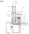
- FIG. 1 shows an embodiment of a contacting device 1 comprising a housing 100 having a first opening 101 for insertion of the electrical conductor 10 and the electrical connector 20 in a cavity 103 of the housing 100 of the contacting device.
- FIG. 1 shows the inserted into the cavity 101 electrical connector 20.
- the electrical conductor 10 is in FIG. 3 shown.
- the housing 100 has a second opening 102 for insertion of the electrical conductor track 30 into the cavity 103 of the housing.
- the electrical conductor track 30 may be arranged, for example, in a body of an electrical component. Part of the electrical track that goes into the FIGS. 1 . 2A . 2 B and 3 can protrude out of the body of the electrical component for contacting.
- the electrical component may be, for example, a motor protection switch, a circuit breaker, a motor protection, a power protection or a thermal relay, to name just a few examples.
- the contacting device 1 can be fastened to the electrical component by means of a fastening element 500, wherein the electrical strip conductor 30 can be arranged through the opening 102 in the cavity 103 of the contacting device.
- the electrical conductor 30 may be formed according to another embodiment as an electrically conductive contact surface of the contacting device.
- the electrically conductive contact surface can be electrically coupled to a further electrical conductor track of an electrical component.
- the contacting device 1 further comprises a contact clip 200, which is arranged in the cavity 103 of the housing 100 of the contacting device.
- the contact clip 200 has a first section 210 for fixing the electrical conductor 10 in a clamping fit on the electrical conductor track 30.
- the contact clip 200 includes a second portion for holding and pressing the plug 20 to the electrical trace 30.
- the second portion 220 of the contact clip is bent in a direction other than the first portion 210 of the contact clip.
- the contacting device 1 moreover comprises a lever 300 for moving the contact clip 200 such that the electrical conductor 10 is detachable from the clamping seat.
- the lever 300 can be moved translationally, for example in the vertical direction downwards, in order to bend away the portion 210 of the contact clip from the electrical conductor 10.
- the lever may, according to a further possible embodiment, be moved in such a way that, when actuated, it performs a pivoting movement or rotational movement about a pivot point in order to bend away the section 210 of the contact clip
- the second portion of the contact clip 200 is shaped such that the electrical connector 20 in a state in which it is pressed by the contact clip 200 to the electrical conductor 30 and held in the cavity 103 of the housing 100 by pulling on the electrical connector from the cavity 103 of the housing 100 is pulled out again.
- the contact clip 200 is in particular shaped in such a way that a necessary pulling force acting on the electrical plug 20 against the insertion direction into the first opening 101 of the housing 100 is smaller than pulling the plug 20 out of the housing 100 smaller than one against the insertion direction in the electrical conductor 10 the first opening 101 of the housing 100 engaging necessary tensile force to pull out the electrical conductor 10 from the housing 100 is.
- the electrical conductor 10 can not be released from the contacting device at least without destroying the function of the contact clip by merely pulling on the electrical conductor. Rather, to release the electrical conductor 10, it is necessary to actuate the lever 300 and to press against the contact clip 200 such that the contact clip 200 is further deflected and releases the electrical conductor 10 so that it is removed again from the cavity 103 of the housing can be.
- the contact clip 200 is fastened to a holding element 600 within the cavity 103 of the contacting device. From there it runs in the cavity 103 to a guide element 700, from which it is bent in the direction of a region of the cavity into which the electrical conductor 10 and the electrical conductor 20 are inserted.
- the first portion 210 of the contact clip 200 is formed as a resilient leg which is bent upon insertion of the electrical conductor 10 through the first opening 101 into the cavity 103 of the housing 100 and generates a restoring force as a result of the bending , Due to the restoring force, the contact clip 200 presses the electrical conductor 10 against the electrical conductor track 30, as in FIG FIG. 3 is shown.
- the first portion 210 of the contact clip 200 has a first end 201 of the contact clip.
- the first portion 210 of the contact clip 200 has an edge 211 at the first end 201.
- the edge 211 is preferably not rounded and aligned at an acute angle to the electrical conductor 10 when the electrical conductor 10 is inserted through the first opening 101 in the cavity 103 of the housing 100.
- the edge 211 is in particular shaped such that the contact force with which the electrical conductor 10 is pressed by the edge 211 against the electrical conductor 30 is increased when the electrical conductor 10 against the insertion direction into the first opening 101 of the housing 100th is pulled.
- the sharp-edged end 201 of the contact clip When the electrical conductor 10 is clamped by the sharp-edged end 201 of the contact clip after being pushed into the cavity 103 of the housing, the sharp-edged end 201 of the contact clip is tilted in the material of the electrical conductor 10. The tilt is increased when an attempt is made to to remove the electrical conductor 10 by pulling against the insertion direction again from the contacting device. This makes it almost impossible, by merely pulling the end of the electrical conductor 10 this again from the Remove contacting device. To release the electrical conductor 10 from the contacting device instead of the lever 300 must be actuated by the lever 300, the contact bracket 200 further deflects.
- the second section 220 of the contact clip 200 has a support region 221, on which the electrical connector 20 rests when the electrical connector is pressed by the contact clip 200 against the electrical conductor track 30.
- the surface of the support portion 221 of the contact clip, which contacts the electrical connector 20 when the electrical connector 20 is pressed by the contact clip 200 against the electrical conductor 30, is larger than the surface with which the edge 211, the electrical connector 10 to the electrical Conductor 30 holds in the press fit.
- the contact clip 200 is in particular shaped in such a way that the second section 220 of the contact clip and thus also the support region 221 runs parallel to the insertion direction of the electrical plug 20 into the cavity 103 of the housing.
- the electrical connector 20 therefore rests only on the support region 221 of the second section 220 of the contact clip 200 and is held by the static friction generated by the contact force of the deflected contact clip.
- the plug can be easily released again from the contacting device by pulling against the direction of insertion into the first opening 101.
- the plug can be additionally held with a latching snap connection to the electrical conductor 30.
- the contacting device 1 comprises a stop element 400, which is designed as a stop for the plug 20.
- a stop element 400 which is designed as a stop for the plug 20. This makes it possible, the plug 20 through the first opening 101 of the housing 100 in the cavity 103 of the housing up to a maximum a depth, so that one end of the plug 20 is disposed in the cavity 103 of the housing from the first portion 210 of the contact clip 200, as for example in the FIGS. 1 . 2A and 2B is shown.
- the stop element 400 of the contacting device may be formed as part of the housing.
- the stop element 400 may be that part of the housing which lies directly next to the first opening 101 of the housing.
- An arrangement for connecting an electric cable 2 to an electrical conductor 30 comprises the contacting device 1 and the electrical connector 20, which is arranged at one end of an electric cable 2 for contacting the electric cable.
- the electrical connector 20 comprises an electrical contact 21 and a non-conductive support element 22, on which the electrical contact 21 is arranged.
- the support element 22 of the electrical connector 20 is designed such that the support element 22 slides during insertion of the electrical connector 20 in the first opening 101 of the contacting along the support portion 221 of the portion 220 of the contact clip 200.
- the electrical connector 20 is thus held in the cavity 103 of the housing of the contacting device by the static friction between the support element 22 of the plug and the support region 221 of the second section 220 of the contact clip 200 of the contacting device.
- the stop element 400 of the contacting device and the electrical connector 20 may have a correspondingly shaped stop element 23.
- the stop element 23 of the plug 20 and the stop element 400 of the contacting device can be designed such that the stop element 23 of the plug 20 abuts against the stop element 400 of the contacting device 1 when the electrical connector 20 is inserted into the first opening 101 of the housing 100 of the contacting device becomes.
- the plug 20 can be inserted through the opening 101 of the housing into the cavity 103 of the housing to a maximum depth, so that the end of the plug 20 of the first portion 210, in particular the sharp-edged end 201 of the first portion 210 of the contact clip 200th , is arranged remotely.
- the plug may have a plurality of pin 24.
- Each plug pin 24 comprises an electrical contact 21 and a non-conductive support element 22 on which the electrical contact 21 is arranged.
- the contacting device 1 also has a correspondingly high number of first openings 101 for inserting the plug pins 24 of the plug and second openings 102 for inserting the strip conductors 30 and on contact bars 200 and levers 300. With the contacting device 1, it is possible, in particular with plugs with multiple plug pins by simply pulling out the plug to solve the various pins from the contacting, without it being necessary to operate for each pin own lever 300 or to release the contact clip for to use each of the pins corresponding tools.
Landscapes
- Details Of Connecting Devices For Male And Female Coupling (AREA)
Abstract
Description
- Die Erfindung betrifft eine Kontaktierungsvorrichtung zum Kontaktieren eines elektrischen Leiters und eines elektrischen Steckers an eine elektrische Leiterbahn. Die Erfindung betrifft des Weiteren eine Anordnung zum Verbinden eines elektrischen Kabels mit einer elektrischen Leiterbahn.
- Bei einer üblichen Kontaktierungsvorrichtung zum Kontaktieren eines elektrischen Leiters an eine elektrische Leiterbahn basierend auf der Push-In-Klemmtechnik wird das abisolierte Ende eines elektrischen Leiters in eine Klemmeinrichtung der Kontaktierungsvorrichtung gesteckt und kann damit an der Kontaktierungsvorrichtung fixiert werden, ohne dass dazu ein Betätigungsmechanismus bedient beziehungsweise ein Werkzeug benutzt werden muss. Die Klemmeinrichtung der Kontaktierungsvorrichtung kann beispielsweise eine vorgespannte Blattfeder aufweisen, die von dem Ende des in die Kontaktierungsvorrichtung eingeschobenen Leiters ausgelenkt wird.
- Die Blattfeder kann ein scharfkantiges Ende aufweisen. Sobald das Ende des elektrischen Leiters über das scharfkantige Ende der Blattfeder rutscht, drückt die Kante der Blattfeder den Leiter gegen eine elektrische Leiterbahn im Inneren des Gehäuses der Kontaktierungsvorrichtung und sichert den elektrischen Leiter durch Einkerben in das Material des Leiters gegen ein Herausrutschen aus der Kontaktierungsvorrichtung. Zum Lösen des elektrischen Leiters aus der Klemmeinrichtung wird die Blattfeder üblicherweise durch einen Betätigungsmechanismus oder ein geeignetes Werkzeug weiter auslenken und gibt somit das Ende des elektrischen Leiters frei, so dass der elektrische Leiter wieder aus der Kontaktierungsvorrichtung herausgezogen werden kann.
- Neben der Kontaktierung eines einzelnen elektrischen Leiters mit der elektrisch leitfähigen Anlagefläche/Leiterbahn im Inneren der Kontaktierungsvorrichtung ist es oftmals erforderlich, einen elektrischen Stecker, der beispielsweise am Ende eines elektrischen Kabels angeordnet ist, an die elektrisch leitfähige Anlagefläche/Leiterbahn anzukoppeln. Im Unterschied zu einem einzelnen elektrischen Leiter, der nach dem Einschieben in die Kontaktierungsvorrichtung gegen ein Herausrutschen gesichert werden muss, soll der Stecker durch einfaches Ziehen entgegen seiner Einschubrichtung wieder aus der Kontaktierungsvorrichtung entnehmbar sein.
- Zum Herausziehen des Steckers aus der Kontaktierungsvorrichtung müsste bei der oben angegebenen Ausführungsform der Kontaktierungsvorrichtung ähnlich wie beim Lösen des elektrischen Leiters ebenfalls der Betätigungsmechanismus bedient oder ein geeignetes Werkzeug benutzt werden, um den Stecker durch weiteres Auslenken der Blattfeder aus der Klemmeinrichtung der Kontaktierungsvorrichtung zu lösen. Besonders umständlich wird diese Vorgehensweise zum Lösen des Steckers aus der Kontaktierungsvorrichtung insbesondere dann, wenn der Stecker eine Vielzahl von Steckstiften, die in einer entsprechenden Vielzahl von Klemmeinrichtungen der Kontaktierungsvorrichtung fixiert sind, aufweist. In diesem Fall müssten zum Lösen des Steckers gleichzeitig sämtliche Betätigungsmechanismen bedient oder eine Vielzahl von Werkzeugen gleichzeitig benutzt werden, um die einzelnen Blattfedern zum Freigeben der Steckstifte weg zu biegen.
- Ein Anliegen der vorliegenden Erfindung ist es, eine Kontaktierungsvorrichtung zum Kontaktieren eines elektrischen Leiters und eines elektrischen Steckers an eine elektrische Leiterbahn anzugeben, mit der es ermöglicht wird, den elektrischen Leiter und den elektrischen Stecker sicher an der elektrischen Leiterbahn zu kontaktieren, wobei der elektrische Leiter gegen ein Herausrutschen aus der Kontaktierungsvorrichtung gesichert ist und der elektrische Stecker zwar sicher in der Kontaktierungsvorrichtung gehalten, jedoch durch einfaches Ziehen entgegen seiner Einschubrichtung aus der Kontaktierungsvorrichtung wieder entnehmbar ist. Ein weiteres Anliegen der vorliegenden Erfindung ist es, eine Anordnung zum Verbinden eines elektrischen Kabels mit einer elektrischen Leiterbahn anzugeben, wobei das elektrische Kabel einerseits sicher mit der elektrischen Leiterbahn verbunden werden kann und die Verbindung andererseits auf leichte Weise wieder gelöst werden kann.
- Eine Ausführungsform einer entsprechend ausgebildeten Kontaktierungsvorrichtung zum Kontaktieren eines elektrischen Leiters und eines elektrischen Steckers an eine elektrische Leiterbahn ist in Patentanspruch 1 angegeben.
- Der Kontaktbügel der Kontaktierungsvorrichtung ist als eine Klemmfeder ausgebildet und weist eine solche Geometrie auf, dass der elektrische Leiter an einem ersten Abschnitt des Kontaktbügels, insbesondere einem scharfkantigen Ende des ersten Abschnitts des Kontaktbügels, anliegt und durch ein Einkerben des scharfkantigen Endes des Kontaktbügels in das Material des elektrischen Leiters gegen ein Herausrutschen aus der Kontaktierungsvorrichtung gesichert ist. Der in die Kontaktierungsvorrichtung eingeschobene elektrische Stecker liegt hingegen an einem zweiten Abschnitt des Kontaktbügels, der anders als der erste Abschnitt gebogen ist, an. Der zweite Abschnitt des Kontaktbügels weist eine speziell geformten Ausprägung, die keine Kante hat, auf.
- Gemäß einer möglichen Ausführungsform umfasst die Kontaktierungsvorrichtung ein Anschlagelement und der Stecker weist ein dazu entsprechend komplementär geformtes Anschlagelement auf. Beim Einschieben in die Kontaktierungsvorrichtung liegt der Stecker mit seinem Anschlagelement an dem Anschlagelement der Kontaktierungsvorrichtung an und kann dadurch nicht so weit in die Kontaktierungsvorrichtung eingeführt werden kann, dass er das scharfkantige Ende des Kontaktbügels berührt. Der elektrische Stecker wird durch die von der Anpresskraft des ausgelenkten zweiten Abschnitts des Kontaktbügels erzeugten Haftreibung gehalten, kann aber bei Überwindung dieser Reibkraft wieder aus der Kontaktierungsvorrichtung herausgezogen werden, ohne dass der Kontaktbügel dazu durch einen entsprechend ausgebildeten Betätigungsmechanismus der Kontaktierungsvorrichtung oder ein spezielles Werkzeug weiter ausgelenkt werden muss.
- Eine Ausführungsform einer Anordnung zum Verbinden eines elektrischen Kabels mit einer elektrischen Leiterbahn ist im Patentanspruch 8 angegeben.
- Die Erfindung wird im Folgenden anhand von Figuren, die Ausführungsformen der Kontaktierungsvorrichtung und der Anordnung zum Verbinden eines elektrischen Kabels mit einer elektrischen Leiterbahn zeigen, näher erläutert. Es zeigen:
-
Figur 1 einen Querschnitt durch eine Ausführungsform einer Kontaktierungsvorrichtung zum Kontaktieren eines elektrischen Leiters und eines elektrischen Steckers an eine elektrische Leiterbahn. -
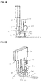
Figur 2A einen Kontaktbügel und einen Hebel zum Bewegen des Kontaktbügels der Kontaktierungsvorrichtung mit einem elektrischen Stecker, der von dem Kontaktbügel an eine elektrische Leiterbahn angedrückt wird in einer Querschnittsdarstellung. -
Figur 2B einen Kontaktbügel und einen Hebel zum Bewegen des Kontaktbügels der Kontaktierungsvorrichtung mit einem elektrischen Stecker, der von dem Kontaktbügel an eine elektrische Leiterbahn angedrückt wird, in einer räumlichen Darstellung. -
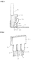
Figur 3 einen Kontaktbügel und einen Hebel zum Bewegen des Kontaktbügels der Kontaktierungsvorrichtung mit einem elektrischen Leiter, der von dem Kontaktbügel an eine elektrische Leiterbahn angedrückt wird, in einer Querschnittsdarstellung. -
Figur 4 eine Ausführungsform eines elektrischen Steckers zum Verbinden mit einem Kabel. -
Figur 1 zeigt eine Ausführungsform einer Kontaktierungsvorrichtung 1 umfassend ein Gehäuse 100 mit einer ersten Öffnung 101 zum Einschieben des elektrischen Leiters 10 und des elektrischen Steckers 20 in einen Hohlraum 103 des Gehäuses 100 der Kontaktierungsvorrichtung.Figur 1 zeigt den in den Hohlraum 101 eingeschobenen elektrischen Stecker 20. Der elektrische Leiter 10 ist inFigur 3 dargestellt. Das Gehäuse 100 weist eine zweite Öffnung 102 zum Einschieben der elektrischen Leiterbahn 30 in den Hohlraum 103 des Gehäuses auf. - Die elektrische Leiterbahn 30 kann beispielsweise in einem Körper eines elektrischen Bauelements angeordnet sein. Ein Teil der elektrischen Leiterbahn, der in den
Figuren 1 ,2A ,2B und3 gezeigt ist, kann aus dem Körper des elektrischen Bauelements zum Kontaktieren herausragen. Das elektrische Bauelement kann beispielsweise ein Motorschutzschalter, ein Leistungsschutzschalter, ein Motorschutz, ein Leistungsschutz oder ein thermisches Relais sein, um nur einige Beispiele zu nennen. Die Kontaktierungsvorrichtung 1 kann mittels eines Befestigungselements 500 an dem elektrischen Bauelement befestigt werden, wobei die elektrische Leiterbahn 30 durch die Öffnung 102 in dem Hohlraum 103 der Kontaktierungsvorrichtung angeordnet werden kann. - Die elektrische Leiterbahn 30 kann gemäß einer anderen Ausführungsform als eine elektrisch leitfähige Anlagefläche der Kontaktierungsvorrichtung ausgebildet sein. Die elektrisch leitfähige Anlagefläche kann mit einer weiteren elektrischen Leiterbahn eines elektrischen Bauelements elektrisch gekoppelt sein.
- Die Kontaktierungsvorrichtung 1 umfasst des Weiteren einen Kontaktbügel 200, der in dem Hohlraum 103 des Gehäuses 100 der Kontaktierungsvorrichtung angeordnet ist. Der Kontaktbügel 200 weist einen ersten Abschnitt 210 zum Fixieren des elektrischen Leiters 10 im Klemmsitz an der elektrischen Leiterbahn 30 auf. Darüber hinaus umfasst der Kontaktbügel 200 einen zweiten Abschnitt zum Halten und Andrücken des Steckers 20 an die elektrische Leiterbahn 30. Der zweite Abschnitt 220 des Kontaktbügels ist in eine andere Richtung als der erste Abschnitt 210 des Kontaktbügels gebogen. Die Kontaktierungsvorrichtung 1 umfasst darüber hinaus einen Hebel 300 zum Bewegen des Kontaktbügels 200 derart, dass der elektrische Leiter 10 aus dem Klemmsitz lösbar ist. Der Hebel 300 kann dazu translatorisch, beispielsweise in vertikaler Richtung nach unten, bewegt werden, um den Abschnitt 210 des Kontaktbügels von dem elektrischen Leiter 10 wegzubiegen. Der Hebel kann gemäß einer weiteren möglichen Ausführungsform derart bewegt werden, dass er bei einer Betätigung eine Schwenkbewegung beziehungsweise Drehbewegung um einen Drehpunkt ausführt, um den Abschnitt 210 des Kontaktbügels von dem elektrischen Leiter 10 wegzubiegen.
- Der zweite Abschnitt des Kontaktbügels 200 ist derart geformt, dass der elektrische Stecker 20 in einem Zustand, in dem er von dem Kontaktbügel 200 an die elektrische Leiterbahn 30 gedrückt und in dem Hohlraum 103 des Gehäuses 100 gehalten wird, durch ein Ziehen an dem elektrischen Stecker aus dem Hohlraum 103 des Gehäuses 100 wieder herausziehbar ist.
- Der Kontaktbügel 200 ist insbesondere derart geformt, dass eine an dem elektrischen Stecker 20 entgegen der Einschubrichtung in die erste Öffnung 101 des Gehäuses 100 angreifende notwendige Zugkraft zum Herausziehen des Steckers 20 aus dem Gehäuse 100 kleiner als eine an dem elektrischen Leiter 10 entgegen der Einschubrichtung in die erste Öffnung 101 des Gehäuses 100 angreifende notwendige Zugkraft zum Herausziehen des elektrischen Leiters 10 aus dem Gehäuse 100 ist.
- Aufgrund der speziellen Formung des Kontaktbügels ist es dadurch möglich, dass der elektrische Leiter 10 zumindest nicht ohne Zerstörung der Funktion des Kontaktbügels durch ein bloßes Ziehen an dem elektrischen Leiter wieder aus der Kontaktierungsvorrichtung gelöst werden kann. Zum Lösen des elektrischen Leiters 10 ist es vielmehr notwendig, den Hebel 300 zu betätigen und derart gegen den Kontaktbügel 200 zu drücken, dass der Kontaktbügel 200 weiter ausgelenkt wird und den elektrischen Leiter 10 freigibt, so dass dieser wieder aus dem Hohlraum 103 des Gehäuses entnommen werden kann.
- Der Kontaktbügel 200 ist innerhalb des Hohlraums 103 der Kontaktierungsvorrichtung an einem Halteelement 600 befestigt. Von dort verläuft er in dem Hohlraum 103 zu einem Führungselement 700, von dem er in Richtung zu einem Bereich des Hohlraums, in den der elektrische Leiter 10 beziehungsweise der elektrische Leiter 20 eingeschoben werden, verbogen wird.
- Gemäß einer möglichen Ausführungsform der Kontaktierungsvorrichtung 1 ist der erste Abschnitt 210 des Kontaktbügels 200 als ein federnder Schenkel ausgeformt, der beim Einschieben des elektrischen Leiters 10 durch die erste Öffnung 101 in den Hohlraum 103 des Gehäuses 100 verbogen wird und in Folge der Verbiegung eine Rückstellkraft erzeugt. Aufgrund der Rückstellkraft drückt der Kontaktbügel 200 den elektrischen Leiter 10 gegen die elektrische Leiterbahn 30, wie in
Figur 3 gezeigt ist. - Gemäß einer möglichen Ausführungsform der Kontaktierungsvorrichtung 1 weist der erste Abschnitt 210 des Kontaktbügels 200 ein erstes Ende 201 des Kontaktbügels auf. Der erste Abschnitt 210 des Kontaktbügels 200 weist an dem ersten Ende 201 eine Kante 211 auf. Die Kante 211 ist vorzugsweise nicht abgerundet und in einem spitzen Winkel auf den elektrischen Leiter 10 ausgerichtet, wenn der elektrische Leiter 10 durch die erste Öffnung 101 in den Hohlraum 103 des Gehäuses 100 eingeschoben wird. Die Kante 211 ist insbesondere derart geformt, dass die Anpresskraft, mit der der elektrische Leiter 10 von der Kante 211 gegen die elektrische Leiterbahn 30 gedrückt wird, erhöht wird, wenn an dem elektrischen Leiter 10 entgegen der Einschubrichtung in die erste Öffnung 101 des Gehäuses 100 gezogen wird.
- Wenn der elektrische Leiter 10 nach dem Einschieben in den Hohlraum 103 des Gehäuses von dem scharfkantigen Ende 201 des Kontaktbügels geklemmt wird, verkantet sich das scharfkantige Ende 201 des Kontaktbügels in dem Material des elektrischen Leiters 10. Die Verkantung wird noch erhöht, wenn versucht wird, den elektrischen Leiter 10 durch ein Ziehen entgegen der Einschubrichtung wieder aus der Kontaktierungsvorrichtung zu entfernen. Dadurch ist es nahezu unmöglich, durch bloßes Ziehen am Ende des elektrischen Leiters 10 diesen wieder aus der Kontaktierungsvorrichtung zu entnehmen. Zum Lösen des elektrischen Leiters 10 aus der Kontaktierungsvorrichtung muss stattdessen der Hebel 300 betätigt werden, indem der Hebel 300 den Kontaktbügel 200 weiter auslenkt.
- Gemäß einer weiteren Ausführungsform der Kontaktierungsvorrichtung weist der zweite Abschnitt 220 des Kontaktbügels 200 einen Auflagebereich 221 auf, auf dem der elektrische Stecker 20 aufliegt, wenn der elektrische Stecker von dem Kontaktbügel 200 gegen die elektrische Leiterbahn 30 gedrückt wird. Die Fläche des Auflagebereichs 221 des Kontaktbügels, die den elektrischen Stecker 20 berührt, wenn der elektrische Stecker 20 von dem Kontaktbügel 200 gegen die elektrische Leiterbahn 30 gedrückt wird, ist größer als die Fläche, mit der die Kante 211 den elektrischen Stecker 10 an der elektrischen Leiterbahn 30 im Klemmsitz hält.
- Der Kontaktbügel 200 ist insbesondere derart geformt, dass der zweite Abschnitt 220 des Kontaktbügels und damit auch der Auflagebereich 221 parallel zur Einschubrichtung des elektrischen Steckers 20 in den Hohlraum 103 des Gehäuses verläuft. Der elektrische Stecker 20 liegt daher lediglich an dem Auflagebereich 221 des zweiten Abschnitts 220 des Kontaktbügels 200 an und wird durch die von der Anpresskraft des ausgelenkten Kontaktbügels erzeugten Haftreibung gehalten. Bei Überwindung dieser Reibkraft kann der Stecker durch ein Ziehen entgegen der Einschubrichtung in die erste Öffnung 101 wieder leicht aus der Kontaktierungsvorrichtung gelöst werden. Hierzu ist es nicht notwendig, den Hebel 300 oder ein entsprechend speziell geformtes Werkzeug zu benutzen.
- Gegen ein durch Erschütterung oder Schaltimpulse verursachtes Herausrutschen der Steckstifte des elektrischen Steckers kann der Stecker zusätzlich mit einer rastenden Schnappverbindung an der elektrischen Leiterbahn 30 gehalten werden.
- Gemäß einer weiteren möglichen Ausführungsform umfasst die Kontaktierungsvorrichtung 1 ein Anschlagelement 400, das als ein Anschlag für den Stecker 20 ausgebildet ist. Dadurch ist es möglich, den Stecker 20 durch die erste Öffnung 101 des Gehäuses 100 in den Hohlraum 103 des Gehäuses bis maximal zu einer Tiefe einzuschieben, so dass ein Ende des Steckers 20 in dem Hohlraum 103 des Gehäuses von dem ersten Abschnitt 210 des Kontaktbügels 200 entfernt angeordnet ist, wie dies beispielsweise in den
Figuren 1 ,2A und 2B gezeigt ist. - Das Anschlagelement 400 der Kontaktierungsvorrichtung kann als Teil des Gehäuses ausgebildet sein. Insbesondere kann das Anschlagelement 400 derjenige Teil des Gehäuses sein, der unmittelbar neben der ersten Öffnung 101 des Gehäuses liegt. Beim Einschieben des elektrischen Steckers 20 in die Öffnung 101 schlägt der elektrische Stecker an dem Anschlagelement 400 der Kontaktierungsvorrichtung an und kann somit nicht weiter in den Hohlraum 103 des Gehäuses eingeschoben werden. Dadurch kommt das Ende des elektrischen Steckers 20 nicht in Kontakt mit dem scharfkantigen Ende 201 des Kontaktbügels 200.
- Eine Anordnung zum Verbinden eines elektrischen Kabels 2 mit einer elektrischen Leiterbahn 30 umfasst die Kontaktierungsvorrichtung 1 und den elektrischen Stecker 20, der an einem Ende eines elektrischen Kabels 2 zum Kontaktieren des elektrischen Kabels angeordnet ist. Der elektrische Stecker 20 umfasst einen elektrischen Kontakt 21 und ein nicht leitendes Auflageelement 22, auf dem der elektrische Kontakt 21 angeordnet ist.
- Beim Einschieben des elektrischen Steckers 20 in die erste Öffnung 101 des Gehäuses 100 der Kontaktierungsvorrichtung wird der Auflagebereich 221 des zweiten Abschnitts 220 des Kontaktbügels 200 gegen das nicht leitende Auflageelement 22 des elektrischen Steckers 20 gedrückt. Wenn die elektrische Leiterbahn 30 in die zweite Öffnung 102 des Gehäuses 100 der Kontaktierungsvorrichtung eingeschoben ist, wird der elektrische Kontakt 21 von der Anpresskraft des zweiten Abschnitts 220 des Kontaktbügels 200 gegen die elektrische Leiterbahn 30 gedrückt.
- Gemäß einer möglichen Ausführungsform ist das Auflageelement 22 des elektrischen Steckers 20 derart ausgebildet, dass das Auflageelement 22 beim Einschieben des elektrischen Steckers 20 in die erste Öffnung 101 der Kontaktierungsvorrichtung entlang des Auflagebereichs 221 des Abschnitts 220 des Kontaktbügels 200 gleitet. Der elektrische Stecker 20 wird somit durch die Haftreibung zwischen dem Auflageelement 22 des Steckers und dem Auflagebereich 221 des zweiten Abschnitts 220 des Kontaktbügels 200 der Kontaktierungsvorrichtung in dem Hohlraum 103 des Gehäuses der Kontaktierungsvorrichtung gehalten.
- Entsprechend dem Anschlagelement 400 der Kontaktierungsvorrichtung kann auch der elektrische Stecker 20 ein entsprechend geformtes Anschlagelement 23 aufweisen. Das Anschlagelement 23 des Steckers 20 und das Anschlagelement 400 der Kontaktierungsvorrichtung können derart zueinander ausgebildet sein, dass das Anschlagelement 23 des Steckers 20 gegen das Anschlagelement 400 der Kontaktierungsvorrichtung 1 anschlägt, wenn der elektrische Stecker 20 in die erste Öffnung 101 des Gehäuses 100 der Kontaktierungsvorrichtung eingeschoben wird. Dadurch kann der Stecker 20 durch die Öffnung 101 des Gehäuses in den Hohlraum 103 des Gehäuses bis maximal zu einer Tiefe eingeschoben werden, so dass das Ende des Steckers 20 von dem ersten Abschnitt 210, insbesondere dem scharfkantigen Ende 201 des ersten Abschnitts 210 des Kontaktbügels 200, entfernt angeordnet ist.
- Gemäß der in
Figur 4 gezeigten Ausführungsform des elektrischen Steckers kann der Stecker mehrere Steckstift 24 aufweisen. Jeder Steckstift 24 umfasst einen elektrischen Kontakt 21 und ein nicht leitendes Auflageelement 22, auf dem der elektrische Kontakt 21 angeordnet ist. Entsprechend der Anzahl der Steckstifte weist auch die Kontaktierungsvorrichtung 1 eine entsprechend hohe Anzahl an ersten Öffnungen 101 zum Einschieben der Steckstifte 24 des Steckers und an zweiten Öffnungen 102 zum Einschieben der Leiterbahnen 30 sowie an Kontaktbügeln 200 und Hebeln 300 auf. Mit der Kontaktierungsvorrichtung 1 wird es ermöglicht, insbesondere bei Steckern mit mehreren Steckstiften durch ein einfaches Herausziehen des Steckers die verschiedenen Steckstifte aus der Kontaktierungsvorrichtung zu lösen, ohne dass es notwendig ist, für jeden Steckstift einen eigenen Hebel 300 zu betätigen oder zum Lösen der Kontaktbügel für jeden der Steckstifte entsprechende Werkzeuge zu benutzen. -
- 1
- Kontaktierungsvorrichtung
- 2
- Kabel
- 10
- elektrischer Leiter
- 20
- elektrischer Stecker
- 21
- elektrischer Kontakt des Steckers
- 22
- Auflageelement des Steckers
- 23
- Anschlagelement des Steckers
- 24
- Steckstifte des Steckers
- 30
- elektrische Leiterbahn
- 100
- Gehäuse
- 101
- erste Öffnung des Gehäuses
- 102
- zweite Öffnung des Gehäuses
- 103
- Hohlraum
- 200
- Kontaktbügel
- 201
- erstes Ende des Kontaktbügels
- 210
- erster Abschnitt des Kontaktbügels
- 211
- Kante des Kontaktbügels
- 220
- zweiter Abschnitt des Kontaktbügels
- 221
- Auflagebereich des Kontaktbügels
- 300
- Hebel
- 400
- Anschlagelement
- 500
- Befestigungselement
- 600
- Halteelement
- 700
- Führungselement
Claims (10)
- Kontaktierungsvorrichtung zum Kontaktieren eines elektrischen Leiters und eines elektrischen Steckers an eine elektrische Leiterbahn, umfassend:- ein Gehäuse (100) mit einer ersten Öffnung (101) zum Einschieben des elektrischen Leiters (10) und des elektrischen Steckers (20) in einen Hohlraum (103) des Gehäuses (100) und mit einer zweiten Öffnung (102) zum Einschieben der elektrischen Leiterbahn (30) in den Hohlraum (103) des Gehäuses,- einen Kontaktbügel (200), der in dem Hohlraum (103) des Gehäuses angeordnet ist, mit einem ersten Abschnitt (210) zum Fixieren des elektrischen Leiters (10) im Klemmsitz an der elektrischen Leiterbahn (30) und mit einem zweiten Abschnitt (220) zum Halten und Andrücken des elektrischen Steckers (20) an die elektrische Leiterbahn (30), wobei der zweite Abschnitt (220) in eine andere Richtung als der erste Abschnitt (210) gebogen ist,- einen Hebel (300) zum Bewegen des Kontaktbügels (200) derart, dass der elektrische Leiter (10) aus dem Klemmsitz lösbar ist,- wobei der zweite Abschnitt (220) des Kontaktbügel (200) derart geformt ist, dass der elektrische Stecker (20) in einem Zustand, in dem er von dem Kontaktbügel (200) an die elektrische Leiterbahn (30) gedrückt und in dem Hohlraum (103) des Gehäuses gehalten wird, durch ein Ziehen an dem elektrischen Stecker (20) aus dem Hohlraum (103) des Gehäuses herausziehbar ist.
- Kontaktierungsvorrichtung nach Anspruch 1,
wobei der Kontaktbügel (200) derart geformt ist, dass eine an dem elektrischen Stecker (20) entgegen der Einschubrichtung in die erste Öffnung (101) des Gehäuses (100) angreifende notwendige Zugkraft zum Herausziehen des elektrischen Steckers (20) aus dem Gehäuse (100) kleiner als eine an dem elektrischen Leiter (10) entgegen der Einschubrichtung in die erste Öffnung (101) des Gehäuses (100) angreifende notwendige Zugkraft zum Herausziehen des elektrischen Leiters (10) aus dem Gehäuse (100) ist. - Kontaktierungsvorrichtung nach einem der Ansprüche 1 oder 2,
wobei der erste Abschnitt (210) des Kontaktbügels (200) als ein federnder Schenkel ausgeformt ist, der beim Einschieben des elektrischen Leiters (10) durch die erste Öffnung (101) in den Hohlraum (103) des Gehäuses (100) verbogen wird und infolge der Verbiegung eine Rückstellkraft erzeugt, mit der er den elektrischen Leiter (10) gegen die elektrische Leiterbahn (30) drückt. - Kontaktierungsvorrichtung nach einem der Ansprüche 2 oder 3,- wobei der erste Abschnitt (210) des Kontaktbügels (200) ein erstes Ende (201) des Kontaktbügels aufweist,- wobei der erste Abschnitt (210) des Kontaktbügels (200) an dem ersten Ende (201) des Kontaktbügels eine Kante (211) aufweist,- wobei die Kante (211) derart geformt ist, dass die Anpresskraft, mit der der elektrische Leiter (10) von der Kante (211) an dem ersten Ende (201) des Kontaktbügels (200) gegen die elektrische Leiterbahn (30) gedrückt wird, erhöht wird, wenn an dem elektrischen Leiter (10) entgegen der Einschubrichtung in die erste Öffnung (101) des Gehäuses (100) gezogen wird.
- Kontaktierungsvorrichtung nach einem der Ansprüche 2 bis 4,- wobei der zweite Abschnitt (220) des Kontaktbügels (200) einen Auflagebereich (221) aufweist, auf dem der elektrische Stecker (20) aufliegt, wenn der elektrische Stecker (20) von dem Kontaktbügel (200) gegen die elektrische Leiterbahn (30) gedrückt wird,- wobei die Fläche des Auflagebereichs (221), die den elektrischen Stecker (20) berührt, wenn der elektrische Stecker (20) von dem Kontaktbügel (200) gegen die elektrische Leiterbahn (30) gedrückt wird, größer ist als die Fläche, mit der die Kante (211) den elektrischen Leiter (10) an der elektrischen Leiterbahn (30) im Klemmsitz hält.
- Kontaktierungsvorrichtung nach Anspruch 5,
wobei der Kontaktbügel (200) derart geformt ist, dass der Auflagebereich (221) des zweiten Abschnitts (220) des Kontaktbügels (200) parallel zur Einschubrichtung des elektrischen Steckers (20) verläuft. - Kontaktierungsvorrichtung nach einem der Ansprüche 1 bis 6, umfassend:ein Anschlagelement (400), das als Anschlag für den elektrischen Stecker (20) ausgebildet ist, wodurch der elektrische Stecker (20) durch die erste Öffnung (101) des Gehäuses (100) in den Hohlraum (103) des Gehäuses bis maximal zu einer Tiefe einschiebbar ist, so dass ein Ende des elektrischen Steckers (20) in dem Hohlraum (103) des Gehäuses von dem ersten Abschnitt (210) des Kontaktbügels (200) entfernt angeordnet ist.
- Anordnung zum Verbinden eines elektrischen Kabels mit einer elektrischen Leiterbahn, umfassend:- eine Kontaktierungsvorrichtung (1) nach einem der Ansprüche 1 bis 7,- einen elektrischen Stecker (20), der an einem Ende des elektrischen Kabels (2) zum Kontaktieren des elektrischen Kabels angeordnet ist,- wobei der elektrische Stecker (20) einen elektrischen Kontakt (21) und ein nichtleitendes Auflageelement (22), auf dem der elektrische Kontakt (21) angeordnet ist, aufweist,- wobei der Auflagebereich (221) des zweiten Abschnitts (220) des Kontaktbügels (200) beim Einschieben des elektrischen Steckers (20) in die erste Öffnung (101) des Gehäuses (100) der Kontaktierungsvorrichtung gegen das nichtleitende Auflageelement (22) des elektrischen Steckers (20) gedrückt wird,- wobei der elektrische Kontakt (21) des elektrischen Steckers (20) von der Anpresskraft des zweiten Abschnitts (220) des Kontaktbügels (200) gegen die elektrische Leiterbahn (30) gedrückt wird, wenn die elektrische Leiterbahn (30) in die zweite Öffnung (102) des Gehäuses (100) der Kontaktierungsvorrichtung (1) eingeschoben ist.
- Anordnung nach Anspruch 8,
wobei das Auflageelement (22) des elektrischen Steckers (20) derart ausgebildet ist, dass das Auflageelement (22) beim Einschieben des elektrischen Steckers (20) in die erste Öffnung (101) der Kontaktierungsvorrichtung (1) entlang des Auflagebereichs (221) des zweiten Abschnitts (220) des Kontaktbügels (200) gleitet und der elektrische Stecker (20) durch die Haftreibung zwischen dem Auflageelement (22) des elektrischen Steckers (20) und dem Auflagebereich (221) des zweiten Abschnitt (220) des Kontaktbügels (200) der Kontaktierungsvorrichtung in dem Hohlraum (103) des Gehäuses der Kontaktierungsvorrichtung gehalten wird. - Anordnung nach einem der Ansprüche 8 oder 9,
wobei der elektrische Stecker (20) ein Anschlagelement (23) aufweist, wobei das Anschlagelement (23) des elektrischen Steckers (20) und das Anschlagelement (400) der Kontaktierungsvorrichtung (1) derart zueinander ausgebildet sind, dass das Anschlagelement (23) des elektrischen Steckers (20) gegen das Anschlagelement (400) der Kontaktierungsvorrichtung (1) anschlägt, wodurch der elektrische Stecker (20) durch die erste Öffnung (101) des Gehäuses in den Hohlraum (103) des Gehäuses bis maximal zu einer Tiefe einschiebbar ist, so dass das Ende des elektrischen Steckers (20) von dem ersten Abschnitt (210) des Kontaktbügels (200) entfernt angeordnet ist.
Priority Applications (1)
| Application Number | Priority Date | Filing Date | Title |
|---|---|---|---|
| PL16187433T PL3139445T3 (pl) | 2015-09-07 | 2016-09-06 | Układ do łączenia kabla elektrycznego z elektryczną ścieżką przewodzącą |
Applications Claiming Priority (1)
| Application Number | Priority Date | Filing Date | Title |
|---|---|---|---|
| DE102015114938.9A DE102015114938A1 (de) | 2015-09-07 | 2015-09-07 | Kontaktierungsvorrichtung zum Kontaktieren eines elektrischen Leiters und eines elektrischen Steckers an eine elektrische Leiterbahn |
Publications (2)
| Publication Number | Publication Date |
|---|---|
| EP3139445A1 true EP3139445A1 (de) | 2017-03-08 |
| EP3139445B1 EP3139445B1 (de) | 2020-04-15 |
Family
ID=56876984
Family Applications (1)
| Application Number | Title | Priority Date | Filing Date |
|---|---|---|---|
| EP16187433.4A Active EP3139445B1 (de) | 2015-09-07 | 2016-09-06 | Anordnung zum verbinden eines elektrisches kabels mit einer elektrischen leiterbahn |
Country Status (4)
| Country | Link |
|---|---|
| US (1) | US9793652B2 (de) |
| EP (1) | EP3139445B1 (de) |
| DE (1) | DE102015114938A1 (de) |
| PL (1) | PL3139445T3 (de) |
Cited By (2)
| Publication number | Priority date | Publication date | Assignee | Title |
|---|---|---|---|---|
| WO2023110014A1 (de) * | 2021-12-14 | 2023-06-22 | Harting Electric Stiftung & Co. Kg | Kontaktfederanordnung zur selbstverriegelnden kontaktierung eines elektrischen leiters |
| EP3667827B1 (de) * | 2018-12-11 | 2023-08-30 | Pinyou Zhu | Verdrahtungsendgerät |
Families Citing this family (4)
| Publication number | Priority date | Publication date | Assignee | Title |
|---|---|---|---|---|
| DE102015100823B4 (de) * | 2015-01-21 | 2021-12-09 | Phoenix Contact Gmbh & Co. Kg | Elektrische Anschlussklemme |
| JP6848909B2 (ja) * | 2018-03-14 | 2021-03-24 | オムロン株式会社 | 端子台 |
| DE102019106254B3 (de) * | 2019-03-12 | 2020-03-12 | Phoenix Contact Gmbh & Co. Kg | Stecksystem mit einem Steckverbinderteil und einer Steckeinrichtung |
| EP4037104B1 (de) | 2021-01-27 | 2024-11-20 | Tyco Electronics France SAS | Anschlussblock mit einer leiterschiene mit einem seitlichen abschnitt |
Citations (4)
| Publication number | Priority date | Publication date | Assignee | Title |
|---|---|---|---|---|
| DE20205821U1 (de) * | 2002-04-12 | 2003-08-21 | Weidmueller Interface | Anschlußvorrichtung für Leiter |
| EP1353407A1 (de) * | 2002-04-12 | 2003-10-15 | Weidmüller Interface GmbH & Co. | Anschlussvorrichtung für Leiter |
| EP1867009A1 (de) * | 2005-04-06 | 2007-12-19 | ABB France | Klemmeinrichtung für einen verbindungsanschluss |
| CN203312499U (zh) * | 2013-05-10 | 2013-11-27 | 町洋机电(中国)有限公司 | 弹簧式节约型电连接器 |
Family Cites Families (11)
| Publication number | Priority date | Publication date | Assignee | Title |
|---|---|---|---|---|
| DE102005045596B3 (de) * | 2005-09-23 | 2007-06-21 | Siemens Ag | Feder-Steckklemme |
| DE202006003400U1 (de) * | 2006-03-04 | 2007-07-12 | Weidmüller Interface GmbH & Co. KG | Anschlusssystem mit Direktsteckanschluss |
| DE102008014177A1 (de) * | 2008-03-14 | 2009-09-17 | Phoenix Contact Gmbh & Co. Kg | Reihenklemme und Reihenklemmblock |
| DE102008039232B4 (de) * | 2008-08-22 | 2019-02-28 | Phoenix Contact Gmbh & Co. Kg | Elektrische Anschlußklemme |
| DE102008055776B4 (de) * | 2008-11-04 | 2011-04-07 | Wago Verwaltungsgesellschaft Mbh | Vorrichtung mit einer Federkraftklemme und einem Leitereinführungsstecker |
| US7785134B2 (en) * | 2008-12-30 | 2010-08-31 | General Electric Company | Contact terminal for conductors |
| DE102010010262B9 (de) * | 2010-03-03 | 2014-10-23 | Wago Verwaltungsgesellschaft Mbh | Steckverbinder |
| DE202010014008U1 (de) * | 2010-10-07 | 2012-01-12 | Weidmüller Interface GmbH & Co. KG | Zusatzanschlussstecker |
| DE102011115637B4 (de) | 2011-06-21 | 2014-03-27 | Phoenix Contact Gmbh & Co. Kg | Elektrische Anschlussklemme |
| DE102013101408B4 (de) * | 2013-02-13 | 2021-01-14 | Wago Verwaltungsgesellschaft Mbh | Federkraftklemmelement und Verbindungsklemme |
| US9466911B1 (en) * | 2015-10-16 | 2016-10-11 | Dinkle Enterprise Co., Ltd. | Terminal base having fastening structure |
-
2015
- 2015-09-07 DE DE102015114938.9A patent/DE102015114938A1/de not_active Withdrawn
-
2016
- 2016-09-06 EP EP16187433.4A patent/EP3139445B1/de active Active
- 2016-09-06 PL PL16187433T patent/PL3139445T3/pl unknown
- 2016-09-06 US US15/256,772 patent/US9793652B2/en active Active
Patent Citations (4)
| Publication number | Priority date | Publication date | Assignee | Title |
|---|---|---|---|---|
| DE20205821U1 (de) * | 2002-04-12 | 2003-08-21 | Weidmueller Interface | Anschlußvorrichtung für Leiter |
| EP1353407A1 (de) * | 2002-04-12 | 2003-10-15 | Weidmüller Interface GmbH & Co. | Anschlussvorrichtung für Leiter |
| EP1867009A1 (de) * | 2005-04-06 | 2007-12-19 | ABB France | Klemmeinrichtung für einen verbindungsanschluss |
| CN203312499U (zh) * | 2013-05-10 | 2013-11-27 | 町洋机电(中国)有限公司 | 弹簧式节约型电连接器 |
Cited By (2)
| Publication number | Priority date | Publication date | Assignee | Title |
|---|---|---|---|---|
| EP3667827B1 (de) * | 2018-12-11 | 2023-08-30 | Pinyou Zhu | Verdrahtungsendgerät |
| WO2023110014A1 (de) * | 2021-12-14 | 2023-06-22 | Harting Electric Stiftung & Co. Kg | Kontaktfederanordnung zur selbstverriegelnden kontaktierung eines elektrischen leiters |
Also Published As
| Publication number | Publication date |
|---|---|
| PL3139445T3 (pl) | 2020-11-02 |
| US9793652B2 (en) | 2017-10-17 |
| EP3139445B1 (de) | 2020-04-15 |
| US20170070004A1 (en) | 2017-03-09 |
| DE102015114938A1 (de) | 2017-03-09 |
Similar Documents
| Publication | Publication Date | Title |
|---|---|---|
| EP3369138B1 (de) | Kontaktierungsvorrichtung zum kontaktieren eines elektrischen leiters an eine elektrische leiterbahn | |
| EP3298659B1 (de) | Leiteranschlussklemme | |
| EP3139445B1 (de) | Anordnung zum verbinden eines elektrisches kabels mit einer elektrischen leiterbahn | |
| DE102010014143B4 (de) | Betätigungseinrichtung für eine elektrische Anschlussklemme | |
| EP1207588B1 (de) | Elektrischer Verbinder für flexible Flachkabel oder flexible Leiterplatten | |
| EP3320582B1 (de) | Anschlussklemme | |
| DE202010008028U1 (de) | Anschlussvorrichtung für Leiter | |
| EP1999820A1 (de) | Anschlussklemme für leiterplatten | |
| DE102007024690A1 (de) | Elektrische Anschluß- oder Verbindungsklemme | |
| DE102011051536A1 (de) | Klemmeinheit einer elektrischen Anschlussklemme | |
| EP2135330A1 (de) | Elektrisches übergabemodul | |
| DE102016112831B4 (de) | Anschlussklemme | |
| DE102024119436A1 (de) | Anschlussklemme zum Anschließen einer elektrischen Leitung | |
| EP3005484B1 (de) | Anschluss- oder verbindungsklemme | |
| EP3320583B1 (de) | Anschlussklemme | |
| DE2619035C2 (de) | Schraubenlose Anschluß- und/oder Verbindungsklemme | |
| DE102008039219A1 (de) | Elektrische Anschlussvorrichtung | |
| DE10034589C2 (de) | Anschlußklemme für elektrische Leiter | |
| DE202010018429U1 (de) | Betätigungseinrichtung für eine elektrische Anschlussklemme | |
| EP3685473A1 (de) | Anschlusseinrichtung zum anschliessen einer elektrischen leitung | |
| WO2018036587A1 (de) | Anschlusselement | |
| DE102018121792B4 (de) | Elektrische Steckbuchse | |
| DE2622323B2 (de) | Kontaktvorrichtung zum Anschluß eines elektrischen Leitungsendes | |
| DE3434969C2 (de) | Schraubenlose Anschlußklemme | |
| DE19817062C2 (de) | Klemmvorrichtung für eine elektrische Leitung |
Legal Events
| Date | Code | Title | Description |
|---|---|---|---|
| PUAI | Public reference made under article 153(3) epc to a published international application that has entered the european phase |
Free format text: ORIGINAL CODE: 0009012 |
|
| STAA | Information on the status of an ep patent application or granted ep patent |
Free format text: STATUS: THE APPLICATION HAS BEEN PUBLISHED |
|
| AK | Designated contracting states |
Kind code of ref document: A1 Designated state(s): AL AT BE BG CH CY CZ DE DK EE ES FI FR GB GR HR HU IE IS IT LI LT LU LV MC MK MT NL NO PL PT RO RS SE SI SK SM TR |
|
| AX | Request for extension of the european patent |
Extension state: BA ME |
|
| STAA | Information on the status of an ep patent application or granted ep patent |
Free format text: STATUS: REQUEST FOR EXAMINATION WAS MADE |
|
| 17P | Request for examination filed |
Effective date: 20170714 |
|
| RBV | Designated contracting states (corrected) |
Designated state(s): AL AT BE BG CH CY CZ DE DK EE ES FI FR GB GR HR HU IE IS IT LI LT LU LV MC MK MT NL NO PL PT RO RS SE SI SK SM TR |
|
| STAA | Information on the status of an ep patent application or granted ep patent |
Free format text: STATUS: EXAMINATION IS IN PROGRESS |
|
| 17Q | First examination report despatched |
Effective date: 20171214 |
|
| RAP1 | Party data changed (applicant data changed or rights of an application transferred) |
Owner name: EATON INTELLIGENT POWER LIMITED |
|
| GRAP | Despatch of communication of intention to grant a patent |
Free format text: ORIGINAL CODE: EPIDOSNIGR1 |
|
| STAA | Information on the status of an ep patent application or granted ep patent |
Free format text: STATUS: GRANT OF PATENT IS INTENDED |
|
| RIC1 | Information provided on ipc code assigned before grant |
Ipc: H01R 13/635 20060101ALI20191114BHEP Ipc: H01R 4/48 20060101AFI20191114BHEP Ipc: H01R 9/24 20060101ALN20191114BHEP Ipc: H01R 12/51 20110101ALI20191114BHEP |
|
| INTG | Intention to grant announced |
Effective date: 20191216 |
|
| GRAS | Grant fee paid |
Free format text: ORIGINAL CODE: EPIDOSNIGR3 |
|
| GRAA | (expected) grant |
Free format text: ORIGINAL CODE: 0009210 |
|
| STAA | Information on the status of an ep patent application or granted ep patent |
Free format text: STATUS: THE PATENT HAS BEEN GRANTED |
|
| AK | Designated contracting states |
Kind code of ref document: B1 Designated state(s): AL AT BE BG CH CY CZ DE DK EE ES FI FR GB GR HR HU IE IS IT LI LT LU LV MC MK MT NL NO PL PT RO RS SE SI SK SM TR |
|
| REG | Reference to a national code |
Ref country code: CH Ref legal event code: EP |
|
| REG | Reference to a national code |
Ref country code: DE Ref legal event code: R096 Ref document number: 502016009527 Country of ref document: DE |
|
| REG | Reference to a national code |
Ref country code: IE Ref legal event code: FG4D Free format text: LANGUAGE OF EP DOCUMENT: GERMAN |
|
| REG | Reference to a national code |
Ref country code: AT Ref legal event code: REF Ref document number: 1258382 Country of ref document: AT Kind code of ref document: T Effective date: 20200515 |
|
| REG | Reference to a national code |
Ref country code: CH Ref legal event code: NV Representative=s name: VALIPAT S.A. C/O BOVARD SA NEUCHATEL, CH |
|
| REG | Reference to a national code |
Ref country code: NL Ref legal event code: FP |
|
| REG | Reference to a national code |
Ref country code: LT Ref legal event code: MG4D |
|
| PG25 | Lapsed in a contracting state [announced via postgrant information from national office to epo] |
Ref country code: FI Free format text: LAPSE BECAUSE OF FAILURE TO SUBMIT A TRANSLATION OF THE DESCRIPTION OR TO PAY THE FEE WITHIN THE PRESCRIBED TIME-LIMIT Effective date: 20200415 Ref country code: SE Free format text: LAPSE BECAUSE OF FAILURE TO SUBMIT A TRANSLATION OF THE DESCRIPTION OR TO PAY THE FEE WITHIN THE PRESCRIBED TIME-LIMIT Effective date: 20200415 Ref country code: IS Free format text: LAPSE BECAUSE OF FAILURE TO SUBMIT A TRANSLATION OF THE DESCRIPTION OR TO PAY THE FEE WITHIN THE PRESCRIBED TIME-LIMIT Effective date: 20200815 Ref country code: GR Free format text: LAPSE BECAUSE OF FAILURE TO SUBMIT A TRANSLATION OF THE DESCRIPTION OR TO PAY THE FEE WITHIN THE PRESCRIBED TIME-LIMIT Effective date: 20200716 Ref country code: NO Free format text: LAPSE BECAUSE OF FAILURE TO SUBMIT A TRANSLATION OF THE DESCRIPTION OR TO PAY THE FEE WITHIN THE PRESCRIBED TIME-LIMIT Effective date: 20200715 Ref country code: LT Free format text: LAPSE BECAUSE OF FAILURE TO SUBMIT A TRANSLATION OF THE DESCRIPTION OR TO PAY THE FEE WITHIN THE PRESCRIBED TIME-LIMIT Effective date: 20200415 Ref country code: PT Free format text: LAPSE BECAUSE OF FAILURE TO SUBMIT A TRANSLATION OF THE DESCRIPTION OR TO PAY THE FEE WITHIN THE PRESCRIBED TIME-LIMIT Effective date: 20200817 |
|
| PG25 | Lapsed in a contracting state [announced via postgrant information from national office to epo] |
Ref country code: RS Free format text: LAPSE BECAUSE OF FAILURE TO SUBMIT A TRANSLATION OF THE DESCRIPTION OR TO PAY THE FEE WITHIN THE PRESCRIBED TIME-LIMIT Effective date: 20200415 Ref country code: BG Free format text: LAPSE BECAUSE OF FAILURE TO SUBMIT A TRANSLATION OF THE DESCRIPTION OR TO PAY THE FEE WITHIN THE PRESCRIBED TIME-LIMIT Effective date: 20200715 Ref country code: LV Free format text: LAPSE BECAUSE OF FAILURE TO SUBMIT A TRANSLATION OF THE DESCRIPTION OR TO PAY THE FEE WITHIN THE PRESCRIBED TIME-LIMIT Effective date: 20200415 Ref country code: HR Free format text: LAPSE BECAUSE OF FAILURE TO SUBMIT A TRANSLATION OF THE DESCRIPTION OR TO PAY THE FEE WITHIN THE PRESCRIBED TIME-LIMIT Effective date: 20200415 |
|
| PG25 | Lapsed in a contracting state [announced via postgrant information from national office to epo] |
Ref country code: AL Free format text: LAPSE BECAUSE OF FAILURE TO SUBMIT A TRANSLATION OF THE DESCRIPTION OR TO PAY THE FEE WITHIN THE PRESCRIBED TIME-LIMIT Effective date: 20200415 |
|
| REG | Reference to a national code |
Ref country code: DE Ref legal event code: R097 Ref document number: 502016009527 Country of ref document: DE |
|
| PG25 | Lapsed in a contracting state [announced via postgrant information from national office to epo] |
Ref country code: DK Free format text: LAPSE BECAUSE OF FAILURE TO SUBMIT A TRANSLATION OF THE DESCRIPTION OR TO PAY THE FEE WITHIN THE PRESCRIBED TIME-LIMIT Effective date: 20200415 Ref country code: ES Free format text: LAPSE BECAUSE OF FAILURE TO SUBMIT A TRANSLATION OF THE DESCRIPTION OR TO PAY THE FEE WITHIN THE PRESCRIBED TIME-LIMIT Effective date: 20200415 Ref country code: RO Free format text: LAPSE BECAUSE OF FAILURE TO SUBMIT A TRANSLATION OF THE DESCRIPTION OR TO PAY THE FEE WITHIN THE PRESCRIBED TIME-LIMIT Effective date: 20200415 Ref country code: CZ Free format text: LAPSE BECAUSE OF FAILURE TO SUBMIT A TRANSLATION OF THE DESCRIPTION OR TO PAY THE FEE WITHIN THE PRESCRIBED TIME-LIMIT Effective date: 20200415 Ref country code: EE Free format text: LAPSE BECAUSE OF FAILURE TO SUBMIT A TRANSLATION OF THE DESCRIPTION OR TO PAY THE FEE WITHIN THE PRESCRIBED TIME-LIMIT Effective date: 20200415 Ref country code: SM Free format text: LAPSE BECAUSE OF FAILURE TO SUBMIT A TRANSLATION OF THE DESCRIPTION OR TO PAY THE FEE WITHIN THE PRESCRIBED TIME-LIMIT Effective date: 20200415 |
|
| PLBE | No opposition filed within time limit |
Free format text: ORIGINAL CODE: 0009261 |
|
| STAA | Information on the status of an ep patent application or granted ep patent |
Free format text: STATUS: NO OPPOSITION FILED WITHIN TIME LIMIT |
|
| PG25 | Lapsed in a contracting state [announced via postgrant information from national office to epo] |
Ref country code: SK Free format text: LAPSE BECAUSE OF FAILURE TO SUBMIT A TRANSLATION OF THE DESCRIPTION OR TO PAY THE FEE WITHIN THE PRESCRIBED TIME-LIMIT Effective date: 20200415 |
|
| 26N | No opposition filed |
Effective date: 20210118 |
|
| PG25 | Lapsed in a contracting state [announced via postgrant information from national office to epo] |
Ref country code: MC Free format text: LAPSE BECAUSE OF FAILURE TO SUBMIT A TRANSLATION OF THE DESCRIPTION OR TO PAY THE FEE WITHIN THE PRESCRIBED TIME-LIMIT Effective date: 20200415 |
|
| PG25 | Lapsed in a contracting state [announced via postgrant information from national office to epo] |
Ref country code: SI Free format text: LAPSE BECAUSE OF FAILURE TO SUBMIT A TRANSLATION OF THE DESCRIPTION OR TO PAY THE FEE WITHIN THE PRESCRIBED TIME-LIMIT Effective date: 20200415 |
|
| REG | Reference to a national code |
Ref country code: BE Ref legal event code: MM Effective date: 20200930 |
|
| PG25 | Lapsed in a contracting state [announced via postgrant information from national office to epo] |
Ref country code: LU Free format text: LAPSE BECAUSE OF NON-PAYMENT OF DUE FEES Effective date: 20200906 |
|
| PG25 | Lapsed in a contracting state [announced via postgrant information from national office to epo] |
Ref country code: BE Free format text: LAPSE BECAUSE OF NON-PAYMENT OF DUE FEES Effective date: 20200930 Ref country code: IE Free format text: LAPSE BECAUSE OF NON-PAYMENT OF DUE FEES Effective date: 20200906 |
|
| PG25 | Lapsed in a contracting state [announced via postgrant information from national office to epo] |
Ref country code: TR Free format text: LAPSE BECAUSE OF FAILURE TO SUBMIT A TRANSLATION OF THE DESCRIPTION OR TO PAY THE FEE WITHIN THE PRESCRIBED TIME-LIMIT Effective date: 20200415 Ref country code: MT Free format text: LAPSE BECAUSE OF FAILURE TO SUBMIT A TRANSLATION OF THE DESCRIPTION OR TO PAY THE FEE WITHIN THE PRESCRIBED TIME-LIMIT Effective date: 20200415 Ref country code: CY Free format text: LAPSE BECAUSE OF FAILURE TO SUBMIT A TRANSLATION OF THE DESCRIPTION OR TO PAY THE FEE WITHIN THE PRESCRIBED TIME-LIMIT Effective date: 20200415 |
|
| PG25 | Lapsed in a contracting state [announced via postgrant information from national office to epo] |
Ref country code: MK Free format text: LAPSE BECAUSE OF FAILURE TO SUBMIT A TRANSLATION OF THE DESCRIPTION OR TO PAY THE FEE WITHIN THE PRESCRIBED TIME-LIMIT Effective date: 20200415 |
|
| REG | Reference to a national code |
Ref country code: AT Ref legal event code: MM01 Ref document number: 1258382 Country of ref document: AT Kind code of ref document: T Effective date: 20210906 |
|
| PG25 | Lapsed in a contracting state [announced via postgrant information from national office to epo] |
Ref country code: AT Free format text: LAPSE BECAUSE OF NON-PAYMENT OF DUE FEES Effective date: 20210906 |
|
| P01 | Opt-out of the competence of the unified patent court (upc) registered |
Effective date: 20230521 |
|
| PGFP | Annual fee paid to national office [announced via postgrant information from national office to epo] |
Ref country code: NL Payment date: 20250820 Year of fee payment: 10 |
|
| REG | Reference to a national code |
Ref country code: CH Ref legal event code: U11 Free format text: ST27 STATUS EVENT CODE: U-0-0-U10-U11 (AS PROVIDED BY THE NATIONAL OFFICE) Effective date: 20251001 |
|
| PGFP | Annual fee paid to national office [announced via postgrant information from national office to epo] |
Ref country code: DE Payment date: 20250820 Year of fee payment: 10 |
|
| PGFP | Annual fee paid to national office [announced via postgrant information from national office to epo] |
Ref country code: PL Payment date: 20250825 Year of fee payment: 10 Ref country code: IT Payment date: 20250820 Year of fee payment: 10 |
|
| PGFP | Annual fee paid to national office [announced via postgrant information from national office to epo] |
Ref country code: GB Payment date: 20250820 Year of fee payment: 10 |
|
| PGFP | Annual fee paid to national office [announced via postgrant information from national office to epo] |
Ref country code: FR Payment date: 20250821 Year of fee payment: 10 |
|
| PGFP | Annual fee paid to national office [announced via postgrant information from national office to epo] |
Ref country code: CH Payment date: 20251001 Year of fee payment: 10 |