EP3137283B1 - Rechnerisches modell und dreidimensionale (3d) druckverfahren - Google Patents
Rechnerisches modell und dreidimensionale (3d) druckverfahren Download PDFInfo
- Publication number
- EP3137283B1 EP3137283B1 EP14891054.0A EP14891054A EP3137283B1 EP 3137283 B1 EP3137283 B1 EP 3137283B1 EP 14891054 A EP14891054 A EP 14891054A EP 3137283 B1 EP3137283 B1 EP 3137283B1
- Authority
- EP
- European Patent Office
- Prior art keywords
- sinterable material
- modifying agent
- layer
- temperature
- agent
- Prior art date
- Legal status (The legal status is an assumption and is not a legal conclusion. Google has not performed a legal analysis and makes no representation as to the accuracy of the status listed.)
- Active
Links
- 238000000034 method Methods 0.000 title claims description 54
- 238000007639 printing Methods 0.000 title claims description 18
- 238000005094 computer simulation Methods 0.000 title claims description 9
- 239000003795 chemical substances by application Substances 0.000 claims description 311
- 239000000463 material Substances 0.000 claims description 210
- 230000005855 radiation Effects 0.000 claims description 40
- 238000004519 manufacturing process Methods 0.000 claims description 39
- 238000009792 diffusion process Methods 0.000 claims description 31
- 238000010146 3D printing Methods 0.000 claims description 22
- 238000012360 testing method Methods 0.000 claims description 19
- XLYOFNOQVPJJNP-UHFFFAOYSA-N water Substances O XLYOFNOQVPJJNP-UHFFFAOYSA-N 0.000 claims description 18
- 238000005245 sintering Methods 0.000 claims description 15
- 239000004094 surface-active agent Substances 0.000 claims description 14
- 239000006184 cosolvent Substances 0.000 claims description 12
- 238000010438 heat treatment Methods 0.000 claims description 12
- 230000008859 change Effects 0.000 claims description 10
- 230000001965 increasing effect Effects 0.000 claims description 8
- 238000013508 migration Methods 0.000 claims description 7
- 230000005012 migration Effects 0.000 claims description 7
- 230000003115 biocidal effect Effects 0.000 claims description 6
- 239000003139 biocide Substances 0.000 claims description 6
- 230000008569 process Effects 0.000 claims description 6
- 238000003860 storage Methods 0.000 claims description 5
- 230000036962 time dependent Effects 0.000 claims description 3
- 230000004048 modification Effects 0.000 claims 1
- 238000012986 modification Methods 0.000 claims 1
- 239000010410 layer Substances 0.000 description 129
- 239000002245 particle Substances 0.000 description 35
- 229920000642 polymer Polymers 0.000 description 15
- 230000000694 effects Effects 0.000 description 14
- 238000012545 processing Methods 0.000 description 14
- 238000004581 coalescence Methods 0.000 description 10
- 206010073306 Exposure to radiation Diseases 0.000 description 9
- 230000008018 melting Effects 0.000 description 9
- 238000002844 melting Methods 0.000 description 9
- 239000000976 ink Substances 0.000 description 8
- -1 polyethylene Polymers 0.000 description 8
- 238000001816 cooling Methods 0.000 description 7
- 238000012937 correction Methods 0.000 description 7
- 238000001704 evaporation Methods 0.000 description 7
- 238000012935 Averaging Methods 0.000 description 6
- PEDCQBHIVMGVHV-UHFFFAOYSA-N Glycerine Chemical compound OCC(O)CO PEDCQBHIVMGVHV-UHFFFAOYSA-N 0.000 description 6
- 230000000052 comparative effect Effects 0.000 description 6
- 230000008020 evaporation Effects 0.000 description 6
- 239000002904 solvent Substances 0.000 description 6
- 238000004836 empirical method Methods 0.000 description 5
- 238000005259 measurement Methods 0.000 description 5
- 230000015654 memory Effects 0.000 description 5
- 239000004677 Nylon Substances 0.000 description 4
- 229920000299 Nylon 12 Polymers 0.000 description 4
- 238000010521 absorption reaction Methods 0.000 description 4
- 230000006399 behavior Effects 0.000 description 4
- 239000012530 fluid Substances 0.000 description 4
- 239000000203 mixture Substances 0.000 description 4
- 229920001778 nylon Polymers 0.000 description 4
- 230000003287 optical effect Effects 0.000 description 4
- NLKNQRATVPKPDG-UHFFFAOYSA-M potassium iodide Chemical compound [K+].[I-] NLKNQRATVPKPDG-UHFFFAOYSA-M 0.000 description 4
- 239000000843 powder Substances 0.000 description 4
- LCZVSXRMYJUNFX-UHFFFAOYSA-N 2-[2-(2-hydroxypropoxy)propoxy]propan-1-ol Chemical compound CC(O)COC(C)COC(C)CO LCZVSXRMYJUNFX-UHFFFAOYSA-N 0.000 description 3
- 239000006096 absorbing agent Substances 0.000 description 3
- 239000000654 additive Substances 0.000 description 3
- 230000000996 additive effect Effects 0.000 description 3
- DMSMPAJRVJJAGA-UHFFFAOYSA-N benzo[d]isothiazol-3-one Chemical compound C1=CC=C2C(=O)NSC2=C1 DMSMPAJRVJJAGA-UHFFFAOYSA-N 0.000 description 3
- 238000009835 boiling Methods 0.000 description 3
- 238000004140 cleaning Methods 0.000 description 3
- 230000003247 decreasing effect Effects 0.000 description 3
- 238000009472 formulation Methods 0.000 description 3
- 230000006870 function Effects 0.000 description 3
- 229920001223 polyethylene glycol Chemical class 0.000 description 3
- HNJBEVLQSNELDL-UHFFFAOYSA-N pyrrolidin-2-one Chemical compound O=C1CCCN1 HNJBEVLQSNELDL-UHFFFAOYSA-N 0.000 description 3
- 239000000126 substance Substances 0.000 description 3
- ARXKVVRQIIOZGF-UHFFFAOYSA-N 1,2,4-butanetriol Chemical compound OCCC(O)CO ARXKVVRQIIOZGF-UHFFFAOYSA-N 0.000 description 2
- WDQFELCEOPFLCZ-UHFFFAOYSA-N 1-(2-hydroxyethyl)pyrrolidin-2-one Chemical compound OCCN1CCCC1=O WDQFELCEOPFLCZ-UHFFFAOYSA-N 0.000 description 2
- NECRQCBKTGZNMH-UHFFFAOYSA-N 3,5-dimethylhex-1-yn-3-ol Chemical compound CC(C)CC(C)(O)C#C NECRQCBKTGZNMH-UHFFFAOYSA-N 0.000 description 2
- 239000005995 Aluminium silicate Substances 0.000 description 2
- 239000004135 Bone phosphate Substances 0.000 description 2
- NBIIXXVUZAFLBC-UHFFFAOYSA-N Phosphoric acid Chemical class OP(O)(O)=O NBIIXXVUZAFLBC-UHFFFAOYSA-N 0.000 description 2
- VYPSYNLAJGMNEJ-UHFFFAOYSA-N Silicium dioxide Chemical compound O=[Si]=O VYPSYNLAJGMNEJ-UHFFFAOYSA-N 0.000 description 2
- 239000004115 Sodium Silicate Substances 0.000 description 2
- UIIMBOGNXHQVGW-UHFFFAOYSA-M Sodium bicarbonate Chemical compound [Na+].OC([O-])=O UIIMBOGNXHQVGW-UHFFFAOYSA-M 0.000 description 2
- 239000011149 active material Substances 0.000 description 2
- 239000013543 active substance Substances 0.000 description 2
- 235000012211 aluminium silicate Nutrition 0.000 description 2
- 239000000440 bentonite Substances 0.000 description 2
- 235000012216 bentonite Nutrition 0.000 description 2
- 238000009529 body temperature measurement Methods 0.000 description 2
- 235000019347 bone phosphate Nutrition 0.000 description 2
- WERYXYBDKMZEQL-UHFFFAOYSA-N butane-1,4-diol Chemical compound OCCCCO WERYXYBDKMZEQL-UHFFFAOYSA-N 0.000 description 2
- 235000012215 calcium aluminium silicate Nutrition 0.000 description 2
- 239000000404 calcium aluminium silicate Substances 0.000 description 2
- 235000012251 calcium ferrocyanide Nutrition 0.000 description 2
- 239000000279 calcium ferrocyanide Substances 0.000 description 2
- 239000001506 calcium phosphate Substances 0.000 description 2
- 239000000378 calcium silicate Substances 0.000 description 2
- 235000012241 calcium silicate Nutrition 0.000 description 2
- 238000006243 chemical reaction Methods 0.000 description 2
- 230000001419 dependent effect Effects 0.000 description 2
- 239000004205 dimethyl polysiloxane Substances 0.000 description 2
- 235000013870 dimethyl polysiloxane Nutrition 0.000 description 2
- 239000000194 fatty acid Substances 0.000 description 2
- 239000000391 magnesium silicate Substances 0.000 description 2
- HQKMJHAJHXVSDF-UHFFFAOYSA-L magnesium stearate Chemical compound [Mg+2].CCCCCCCCCCCCCCCCCC([O-])=O.CCCCCCCCCCCCCCCCCC([O-])=O HQKMJHAJHXVSDF-UHFFFAOYSA-L 0.000 description 2
- 239000000049 pigment Substances 0.000 description 2
- 229920000139 polyethylene terephthalate Polymers 0.000 description 2
- 239000005020 polyethylene terephthalate Substances 0.000 description 2
- 235000012219 potassium aluminium silicate Nutrition 0.000 description 2
- 239000000441 potassium aluminium silicate Substances 0.000 description 2
- 239000000276 potassium ferrocyanide Substances 0.000 description 2
- 235000012249 potassium ferrocyanide Nutrition 0.000 description 2
- 235000019814 powdered cellulose Nutrition 0.000 description 2
- 230000009467 reduction Effects 0.000 description 2
- 235000012239 silicon dioxide Nutrition 0.000 description 2
- 239000000377 silicon dioxide Substances 0.000 description 2
- 235000012217 sodium aluminium silicate Nutrition 0.000 description 2
- 239000000429 sodium aluminium silicate Substances 0.000 description 2
- 235000012247 sodium ferrocyanide Nutrition 0.000 description 2
- 239000000264 sodium ferrocyanide Substances 0.000 description 2
- 238000007711 solidification Methods 0.000 description 2
- 230000008023 solidification Effects 0.000 description 2
- 239000012798 spherical particle Substances 0.000 description 2
- 238000003892 spreading Methods 0.000 description 2
- 230000007480 spreading Effects 0.000 description 2
- UWHCKJMYHZGTIT-UHFFFAOYSA-N tetraethylene glycol Chemical compound OCCOCCOCCOCCO UWHCKJMYHZGTIT-UHFFFAOYSA-N 0.000 description 2
- 238000012546 transfer Methods 0.000 description 2
- QORWJWZARLRLPR-UHFFFAOYSA-H tricalcium bis(phosphate) Chemical compound [Ca+2].[Ca+2].[Ca+2].[O-]P([O-])([O-])=O.[O-]P([O-])([O-])=O QORWJWZARLRLPR-UHFFFAOYSA-H 0.000 description 2
- 238000009834 vaporization Methods 0.000 description 2
- 230000008016 vaporization Effects 0.000 description 2
- 238000009736 wetting Methods 0.000 description 2
- LDXJRKWFNNFDSA-UHFFFAOYSA-N 2-(2,4,6,7-tetrahydrotriazolo[4,5-c]pyridin-5-yl)-1-[4-[2-[[3-(trifluoromethoxy)phenyl]methylamino]pyrimidin-5-yl]piperazin-1-yl]ethanone Chemical compound C1CN(CC2=NNN=C21)CC(=O)N3CCN(CC3)C4=CN=C(N=C4)NCC5=CC(=CC=C5)OC(F)(F)F LDXJRKWFNNFDSA-UHFFFAOYSA-N 0.000 description 1
- COBPKKZHLDDMTB-UHFFFAOYSA-N 2-[2-(2-butoxyethoxy)ethoxy]ethanol Chemical compound CCCCOCCOCCOCCO COBPKKZHLDDMTB-UHFFFAOYSA-N 0.000 description 1
- WAEVWDZKMBQDEJ-UHFFFAOYSA-N 2-[2-(2-methoxypropoxy)propoxy]propan-1-ol Chemical compound COC(C)COC(C)COC(C)CO WAEVWDZKMBQDEJ-UHFFFAOYSA-N 0.000 description 1
- KQMCGGGTJKNIMC-UHFFFAOYSA-N 2-hydroxy-3-propyl-2h-furan-5-one Chemical compound CCCC1=CC(=O)OC1O KQMCGGGTJKNIMC-UHFFFAOYSA-N 0.000 description 1
- YLZOPXRUQYQQID-UHFFFAOYSA-N 3-(2,4,6,7-tetrahydrotriazolo[4,5-c]pyridin-5-yl)-1-[4-[2-[[3-(trifluoromethoxy)phenyl]methylamino]pyrimidin-5-yl]piperazin-1-yl]propan-1-one Chemical compound N1N=NC=2CN(CCC=21)CCC(=O)N1CCN(CC1)C=1C=NC(=NC=1)NCC1=CC(=CC=C1)OC(F)(F)F YLZOPXRUQYQQID-UHFFFAOYSA-N 0.000 description 1
- WTFUTSCZYYCBAY-SXBRIOAWSA-N 6-[(E)-C-[[4-[2-(2,3-dihydro-1H-inden-2-ylamino)pyrimidin-5-yl]piperazin-1-yl]methyl]-N-hydroxycarbonimidoyl]-3H-1,3-benzoxazol-2-one Chemical compound C1C(CC2=CC=CC=C12)NC1=NC=C(C=N1)N1CCN(CC1)C/C(=N/O)/C1=CC2=C(NC(O2)=O)C=C1 WTFUTSCZYYCBAY-SXBRIOAWSA-N 0.000 description 1
- UFHFLCQGNIYNRP-UHFFFAOYSA-N Hydrogen Chemical compound [H][H] UFHFLCQGNIYNRP-UHFFFAOYSA-N 0.000 description 1
- JHWNWJKBPDFINM-UHFFFAOYSA-N Laurolactam Chemical compound O=C1CCCCCCCCCCCN1 JHWNWJKBPDFINM-UHFFFAOYSA-N 0.000 description 1
- AFCARXCZXQIEQB-UHFFFAOYSA-N N-[3-oxo-3-(2,4,6,7-tetrahydrotriazolo[4,5-c]pyridin-5-yl)propyl]-2-[[3-(trifluoromethoxy)phenyl]methylamino]pyrimidine-5-carboxamide Chemical compound O=C(CCNC(=O)C=1C=NC(=NC=1)NCC1=CC(=CC=C1)OC(F)(F)F)N1CC2=C(CC1)NN=N2 AFCARXCZXQIEQB-UHFFFAOYSA-N 0.000 description 1
- 229910000503 Na-aluminosilicate Inorganic materials 0.000 description 1
- 229920000571 Nylon 11 Polymers 0.000 description 1
- 229920002292 Nylon 6 Polymers 0.000 description 1
- 229920002302 Nylon 6,6 Polymers 0.000 description 1
- 229920000572 Nylon 6/12 Polymers 0.000 description 1
- ALQSHHUCVQOPAS-UHFFFAOYSA-N Pentane-1,5-diol Chemical compound OCCCCCO ALQSHHUCVQOPAS-UHFFFAOYSA-N 0.000 description 1
- 239000004952 Polyamide Substances 0.000 description 1
- 239000004698 Polyethylene Substances 0.000 description 1
- 239000002202 Polyethylene glycol Chemical class 0.000 description 1
- 239000004743 Polypropylene Substances 0.000 description 1
- 239000004793 Polystyrene Substances 0.000 description 1
- 235000021355 Stearic acid Nutrition 0.000 description 1
- ZJCCRDAZUWHFQH-UHFFFAOYSA-N Trimethylolpropane Chemical compound CCC(CO)(CO)CO ZJCCRDAZUWHFQH-UHFFFAOYSA-N 0.000 description 1
- 238000002835 absorbance Methods 0.000 description 1
- 150000008431 aliphatic amides Chemical class 0.000 description 1
- 150000003973 alkyl amines Chemical class 0.000 description 1
- 229910000147 aluminium phosphate Inorganic materials 0.000 description 1
- 229910000323 aluminium silicate Inorganic materials 0.000 description 1
- PZZYQPZGQPZBDN-UHFFFAOYSA-N aluminium silicate Chemical compound O=[Al]O[Si](=O)O[Al]=O PZZYQPZGQPZBDN-UHFFFAOYSA-N 0.000 description 1
- 238000004458 analytical method Methods 0.000 description 1
- 235000012213 anti-caking agent fatty acid Nutrition 0.000 description 1
- 238000013459 approach Methods 0.000 description 1
- 239000007864 aqueous solution Substances 0.000 description 1
- 235000013405 beer Nutrition 0.000 description 1
- YSJGOMATDFSEED-UHFFFAOYSA-M behentrimonium chloride Chemical compound [Cl-].CCCCCCCCCCCCCCCCCCCCCC[N+](C)(C)C YSJGOMATDFSEED-UHFFFAOYSA-M 0.000 description 1
- 229940075506 behentrimonium chloride Drugs 0.000 description 1
- 229910000278 bentonite Inorganic materials 0.000 description 1
- SVPXDRXYRYOSEX-UHFFFAOYSA-N bentoquatam Chemical compound O.O=[Si]=O.O=[Al]O[Al]=O SVPXDRXYRYOSEX-UHFFFAOYSA-N 0.000 description 1
- 239000011230 binding agent Substances 0.000 description 1
- 230000015572 biosynthetic process Effects 0.000 description 1
- WNCYAPRTYDMSFP-UHFFFAOYSA-N calcium aluminosilicate Chemical compound [Al+3].[Al+3].[Ca+2].[O-][Si]([O-])=O.[O-][Si]([O-])=O.[O-][Si]([O-])=O.[O-][Si]([O-])=O WNCYAPRTYDMSFP-UHFFFAOYSA-N 0.000 description 1
- 229940078583 calcium aluminosilicate Drugs 0.000 description 1
- 235000011010 calcium phosphates Nutrition 0.000 description 1
- 229910052918 calcium silicate Inorganic materials 0.000 description 1
- OYACROKNLOSFPA-UHFFFAOYSA-N calcium;dioxido(oxo)silane Chemical compound [Ca+2].[O-][Si]([O-])=O OYACROKNLOSFPA-UHFFFAOYSA-N 0.000 description 1
- 239000006229 carbon black Substances 0.000 description 1
- 239000001913 cellulose Substances 0.000 description 1
- 239000011248 coating agent Substances 0.000 description 1
- 238000000576 coating method Methods 0.000 description 1
- MRUAUOIMASANKQ-UHFFFAOYSA-N cocamidopropyl betaine Chemical compound CCCCCCCCCCCC(=O)NCCC[N+](C)(C)CC([O-])=O MRUAUOIMASANKQ-UHFFFAOYSA-N 0.000 description 1
- 229940073507 cocamidopropyl betaine Drugs 0.000 description 1
- 238000004891 communication Methods 0.000 description 1
- 239000002826 coolant Substances 0.000 description 1
- 239000011258 core-shell material Substances 0.000 description 1
- 230000002596 correlated effect Effects 0.000 description 1
- 230000000875 corresponding effect Effects 0.000 description 1
- 239000008367 deionised water Substances 0.000 description 1
- 229910021641 deionized water Inorganic materials 0.000 description 1
- 230000000994 depressogenic effect Effects 0.000 description 1
- 238000010586 diagram Methods 0.000 description 1
- 235000014113 dietary fatty acids Nutrition 0.000 description 1
- MTHSVFCYNBDYFN-UHFFFAOYSA-N diethylene glycol Chemical compound OCCOCCO MTHSVFCYNBDYFN-UHFFFAOYSA-N 0.000 description 1
- GXGAKHNRMVGRPK-UHFFFAOYSA-N dimagnesium;dioxido-bis[[oxido(oxo)silyl]oxy]silane Chemical compound [Mg+2].[Mg+2].[O-][Si](=O)O[Si]([O-])([O-])O[Si]([O-])=O GXGAKHNRMVGRPK-UHFFFAOYSA-N 0.000 description 1
- 230000003292 diminished effect Effects 0.000 description 1
- 150000002009 diols Chemical class 0.000 description 1
- FPAFDBFIGPHWGO-UHFFFAOYSA-N dioxosilane;oxomagnesium;hydrate Chemical compound O.[Mg]=O.[Mg]=O.[Mg]=O.O=[Si]=O.O=[Si]=O.O=[Si]=O.O=[Si]=O FPAFDBFIGPHWGO-UHFFFAOYSA-N 0.000 description 1
- XQGPKZUNMMFTAL-UHFFFAOYSA-L dipotassium;hydrogen phosphate;trihydrate Chemical compound O.O.O.[K+].[K+].OP([O-])([O-])=O XQGPKZUNMMFTAL-UHFFFAOYSA-L 0.000 description 1
- SZXQTJUDPRGNJN-UHFFFAOYSA-N dipropylene glycol Chemical compound OCCCOCCCO SZXQTJUDPRGNJN-UHFFFAOYSA-N 0.000 description 1
- 239000006185 dispersion Substances 0.000 description 1
- 238000005516 engineering process Methods 0.000 description 1
- 239000003623 enhancer Substances 0.000 description 1
- 230000002708 enhancing effect Effects 0.000 description 1
- 150000002148 esters Chemical class 0.000 description 1
- 238000011156 evaluation Methods 0.000 description 1
- 238000001125 extrusion Methods 0.000 description 1
- 229930195729 fatty acid Natural products 0.000 description 1
- 238000010304 firing Methods 0.000 description 1
- 150000002334 glycols Chemical class 0.000 description 1
- XXMIOPMDWAUFGU-UHFFFAOYSA-N hexane-1,6-diol Chemical compound OCCCCCCO XXMIOPMDWAUFGU-UHFFFAOYSA-N 0.000 description 1
- 230000002209 hydrophobic effect Effects 0.000 description 1
- 239000003112 inhibitor Substances 0.000 description 1
- 239000011229 interlayer Substances 0.000 description 1
- 239000007788 liquid Substances 0.000 description 1
- 238000003754 machining Methods 0.000 description 1
- 235000010933 magnesium salts of fatty acid Nutrition 0.000 description 1
- 239000001778 magnesium salts of fatty acids Substances 0.000 description 1
- 235000019359 magnesium stearate Nutrition 0.000 description 1
- 229940099273 magnesium trisilicate Drugs 0.000 description 1
- 229910000386 magnesium trisilicate Inorganic materials 0.000 description 1
- 235000019793 magnesium trisilicate Nutrition 0.000 description 1
- 239000000155 melt Substances 0.000 description 1
- QIQXTHQIDYTFRH-UHFFFAOYSA-N octadecanoic acid Chemical compound CCCCCCCCCCCCCCCCCC(O)=O QIQXTHQIDYTFRH-UHFFFAOYSA-N 0.000 description 1
- OQCDKBAXFALNLD-UHFFFAOYSA-N octadecanoic acid Natural products CCCCCCCC(C)CCCCCCCCC(O)=O OQCDKBAXFALNLD-UHFFFAOYSA-N 0.000 description 1
- 230000000149 penetrating effect Effects 0.000 description 1
- 230000000704 physical effect Effects 0.000 description 1
- 229920000435 poly(dimethylsiloxane) Polymers 0.000 description 1
- 229920002647 polyamide Polymers 0.000 description 1
- 239000004417 polycarbonate Substances 0.000 description 1
- 229920000515 polycarbonate Polymers 0.000 description 1
- 229920000573 polyethylene Polymers 0.000 description 1
- 229920005862 polyol Polymers 0.000 description 1
- 150000003077 polyols Chemical class 0.000 description 1
- 229920006324 polyoxymethylene Polymers 0.000 description 1
- 229920001155 polypropylene Polymers 0.000 description 1
- 229920002223 polystyrene Polymers 0.000 description 1
- 238000012805 post-processing Methods 0.000 description 1
- 229920003124 powdered cellulose Polymers 0.000 description 1
- 150000003242 quaternary ammonium salts Chemical class 0.000 description 1
- 238000001953 recrystallisation Methods 0.000 description 1
- 150000003839 salts Chemical class 0.000 description 1
- 238000005488 sandblasting Methods 0.000 description 1
- 239000004065 semiconductor Substances 0.000 description 1
- 239000002356 single layer Substances 0.000 description 1
- URGAHOPLAPQHLN-UHFFFAOYSA-N sodium aluminosilicate Chemical compound [Na+].[Al+3].[O-][Si]([O-])=O.[O-][Si]([O-])=O URGAHOPLAPQHLN-UHFFFAOYSA-N 0.000 description 1
- 235000017557 sodium bicarbonate Nutrition 0.000 description 1
- 229910000030 sodium bicarbonate Inorganic materials 0.000 description 1
- CDBYLPFSWZWCQE-UHFFFAOYSA-L sodium carbonate Substances [Na+].[Na+].[O-]C([O-])=O CDBYLPFSWZWCQE-UHFFFAOYSA-L 0.000 description 1
- 235000011182 sodium carbonates Nutrition 0.000 description 1
- GTSHREYGKSITGK-UHFFFAOYSA-N sodium ferrocyanide Chemical compound [Na+].[Na+].[Na+].[Na+].[Fe+2].N#[C-].N#[C-].N#[C-].N#[C-].N#[C-].N#[C-] GTSHREYGKSITGK-UHFFFAOYSA-N 0.000 description 1
- NTHWMYGWWRZVTN-UHFFFAOYSA-N sodium silicate Chemical compound [Na+].[Na+].[O-][Si]([O-])=O NTHWMYGWWRZVTN-UHFFFAOYSA-N 0.000 description 1
- 229910052911 sodium silicate Inorganic materials 0.000 description 1
- 239000007787 solid Substances 0.000 description 1
- 239000000243 solution Substances 0.000 description 1
- 239000008117 stearic acid Substances 0.000 description 1
- 239000000454 talc Substances 0.000 description 1
- 235000012222 talc Nutrition 0.000 description 1
- XOGGUFAVLNCTRS-UHFFFAOYSA-N tetrapotassium;iron(2+);hexacyanide Chemical compound [K+].[K+].[K+].[K+].[Fe+2].N#[C-].N#[C-].N#[C-].N#[C-].N#[C-].N#[C-] XOGGUFAVLNCTRS-UHFFFAOYSA-N 0.000 description 1
- 239000012815 thermoplastic material Substances 0.000 description 1
- 238000012876 topography Methods 0.000 description 1
- 235000019731 tricalcium phosphate Nutrition 0.000 description 1
- 229940078499 tricalcium phosphate Drugs 0.000 description 1
- 229910000391 tricalcium phosphate Inorganic materials 0.000 description 1
- ZIBGPFATKBEMQZ-UHFFFAOYSA-N triethylene glycol Chemical compound OCCOCCOCCO ZIBGPFATKBEMQZ-UHFFFAOYSA-N 0.000 description 1
- 238000010792 warming Methods 0.000 description 1
- 238000005406 washing Methods 0.000 description 1
- 239000000080 wetting agent Substances 0.000 description 1
Images


Classifications
-
- B—PERFORMING OPERATIONS; TRANSPORTING
- B29—WORKING OF PLASTICS; WORKING OF SUBSTANCES IN A PLASTIC STATE IN GENERAL
- B29C—SHAPING OR JOINING OF PLASTICS; SHAPING OF MATERIAL IN A PLASTIC STATE, NOT OTHERWISE PROVIDED FOR; AFTER-TREATMENT OF THE SHAPED PRODUCTS, e.g. REPAIRING
- B29C64/00—Additive manufacturing, i.e. manufacturing of three-dimensional [3D] objects by additive deposition, additive agglomeration or additive layering, e.g. by 3D printing, stereolithography or selective laser sintering
- B29C64/10—Processes of additive manufacturing
- B29C64/165—Processes of additive manufacturing using a combination of solid and fluid materials, e.g. a powder selectively bound by a liquid binder, catalyst, inhibitor or energy absorber
-
- B—PERFORMING OPERATIONS; TRANSPORTING
- B29—WORKING OF PLASTICS; WORKING OF SUBSTANCES IN A PLASTIC STATE IN GENERAL
- B29C—SHAPING OR JOINING OF PLASTICS; SHAPING OF MATERIAL IN A PLASTIC STATE, NOT OTHERWISE PROVIDED FOR; AFTER-TREATMENT OF THE SHAPED PRODUCTS, e.g. REPAIRING
- B29C64/00—Additive manufacturing, i.e. manufacturing of three-dimensional [3D] objects by additive deposition, additive agglomeration or additive layering, e.g. by 3D printing, stereolithography or selective laser sintering
- B29C64/10—Processes of additive manufacturing
- B29C64/171—Processes of additive manufacturing specially adapted for manufacturing multiple 3D objects
- B29C64/182—Processes of additive manufacturing specially adapted for manufacturing multiple 3D objects in parallel batches
-
- B—PERFORMING OPERATIONS; TRANSPORTING
- B29—WORKING OF PLASTICS; WORKING OF SUBSTANCES IN A PLASTIC STATE IN GENERAL
- B29C—SHAPING OR JOINING OF PLASTICS; SHAPING OF MATERIAL IN A PLASTIC STATE, NOT OTHERWISE PROVIDED FOR; AFTER-TREATMENT OF THE SHAPED PRODUCTS, e.g. REPAIRING
- B29C64/00—Additive manufacturing, i.e. manufacturing of three-dimensional [3D] objects by additive deposition, additive agglomeration or additive layering, e.g. by 3D printing, stereolithography or selective laser sintering
- B29C64/20—Apparatus for additive manufacturing; Details thereof or accessories therefor
- B29C64/205—Means for applying layers
- B29C64/209—Heads; Nozzles
-
- B—PERFORMING OPERATIONS; TRANSPORTING
- B29—WORKING OF PLASTICS; WORKING OF SUBSTANCES IN A PLASTIC STATE IN GENERAL
- B29C—SHAPING OR JOINING OF PLASTICS; SHAPING OF MATERIAL IN A PLASTIC STATE, NOT OTHERWISE PROVIDED FOR; AFTER-TREATMENT OF THE SHAPED PRODUCTS, e.g. REPAIRING
- B29C64/00—Additive manufacturing, i.e. manufacturing of three-dimensional [3D] objects by additive deposition, additive agglomeration or additive layering, e.g. by 3D printing, stereolithography or selective laser sintering
- B29C64/20—Apparatus for additive manufacturing; Details thereof or accessories therefor
- B29C64/205—Means for applying layers
- B29C64/214—Doctor blades
-
- B—PERFORMING OPERATIONS; TRANSPORTING
- B29—WORKING OF PLASTICS; WORKING OF SUBSTANCES IN A PLASTIC STATE IN GENERAL
- B29C—SHAPING OR JOINING OF PLASTICS; SHAPING OF MATERIAL IN A PLASTIC STATE, NOT OTHERWISE PROVIDED FOR; AFTER-TREATMENT OF THE SHAPED PRODUCTS, e.g. REPAIRING
- B29C64/00—Additive manufacturing, i.e. manufacturing of three-dimensional [3D] objects by additive deposition, additive agglomeration or additive layering, e.g. by 3D printing, stereolithography or selective laser sintering
- B29C64/20—Apparatus for additive manufacturing; Details thereof or accessories therefor
- B29C64/227—Driving means
-
- B—PERFORMING OPERATIONS; TRANSPORTING
- B29—WORKING OF PLASTICS; WORKING OF SUBSTANCES IN A PLASTIC STATE IN GENERAL
- B29C—SHAPING OR JOINING OF PLASTICS; SHAPING OF MATERIAL IN A PLASTIC STATE, NOT OTHERWISE PROVIDED FOR; AFTER-TREATMENT OF THE SHAPED PRODUCTS, e.g. REPAIRING
- B29C64/00—Additive manufacturing, i.e. manufacturing of three-dimensional [3D] objects by additive deposition, additive agglomeration or additive layering, e.g. by 3D printing, stereolithography or selective laser sintering
- B29C64/20—Apparatus for additive manufacturing; Details thereof or accessories therefor
- B29C64/264—Arrangements for irradiation
-
- B—PERFORMING OPERATIONS; TRANSPORTING
- B29—WORKING OF PLASTICS; WORKING OF SUBSTANCES IN A PLASTIC STATE IN GENERAL
- B29C—SHAPING OR JOINING OF PLASTICS; SHAPING OF MATERIAL IN A PLASTIC STATE, NOT OTHERWISE PROVIDED FOR; AFTER-TREATMENT OF THE SHAPED PRODUCTS, e.g. REPAIRING
- B29C64/00—Additive manufacturing, i.e. manufacturing of three-dimensional [3D] objects by additive deposition, additive agglomeration or additive layering, e.g. by 3D printing, stereolithography or selective laser sintering
- B29C64/30—Auxiliary operations or equipment
- B29C64/386—Data acquisition or data processing for additive manufacturing
- B29C64/393—Data acquisition or data processing for additive manufacturing for controlling or regulating additive manufacturing processes
-
- B—PERFORMING OPERATIONS; TRANSPORTING
- B29—WORKING OF PLASTICS; WORKING OF SUBSTANCES IN A PLASTIC STATE IN GENERAL
- B29C—SHAPING OR JOINING OF PLASTICS; SHAPING OF MATERIAL IN A PLASTIC STATE, NOT OTHERWISE PROVIDED FOR; AFTER-TREATMENT OF THE SHAPED PRODUCTS, e.g. REPAIRING
- B29C64/00—Additive manufacturing, i.e. manufacturing of three-dimensional [3D] objects by additive deposition, additive agglomeration or additive layering, e.g. by 3D printing, stereolithography or selective laser sintering
- B29C64/40—Structures for supporting 3D objects during manufacture and intended to be sacrificed after completion thereof
-
- B—PERFORMING OPERATIONS; TRANSPORTING
- B29—WORKING OF PLASTICS; WORKING OF SUBSTANCES IN A PLASTIC STATE IN GENERAL
- B29C—SHAPING OR JOINING OF PLASTICS; SHAPING OF MATERIAL IN A PLASTIC STATE, NOT OTHERWISE PROVIDED FOR; AFTER-TREATMENT OF THE SHAPED PRODUCTS, e.g. REPAIRING
- B29C67/00—Shaping techniques not covered by groups B29C39/00 - B29C65/00, B29C70/00 or B29C73/00
-
- B—PERFORMING OPERATIONS; TRANSPORTING
- B33—ADDITIVE MANUFACTURING TECHNOLOGY
- B33Y—ADDITIVE MANUFACTURING, i.e. MANUFACTURING OF THREE-DIMENSIONAL [3-D] OBJECTS BY ADDITIVE DEPOSITION, ADDITIVE AGGLOMERATION OR ADDITIVE LAYERING, e.g. BY 3-D PRINTING, STEREOLITHOGRAPHY OR SELECTIVE LASER SINTERING
- B33Y10/00—Processes of additive manufacturing
-
- B—PERFORMING OPERATIONS; TRANSPORTING
- B33—ADDITIVE MANUFACTURING TECHNOLOGY
- B33Y—ADDITIVE MANUFACTURING, i.e. MANUFACTURING OF THREE-DIMENSIONAL [3-D] OBJECTS BY ADDITIVE DEPOSITION, ADDITIVE AGGLOMERATION OR ADDITIVE LAYERING, e.g. BY 3-D PRINTING, STEREOLITHOGRAPHY OR SELECTIVE LASER SINTERING
- B33Y30/00—Apparatus for additive manufacturing; Details thereof or accessories therefor
-
- B—PERFORMING OPERATIONS; TRANSPORTING
- B33—ADDITIVE MANUFACTURING TECHNOLOGY
- B33Y—ADDITIVE MANUFACTURING, i.e. MANUFACTURING OF THREE-DIMENSIONAL [3-D] OBJECTS BY ADDITIVE DEPOSITION, ADDITIVE AGGLOMERATION OR ADDITIVE LAYERING, e.g. BY 3-D PRINTING, STEREOLITHOGRAPHY OR SELECTIVE LASER SINTERING
- B33Y50/00—Data acquisition or data processing for additive manufacturing
- B33Y50/02—Data acquisition or data processing for additive manufacturing for controlling or regulating additive manufacturing processes
-
- B—PERFORMING OPERATIONS; TRANSPORTING
- B33—ADDITIVE MANUFACTURING TECHNOLOGY
- B33Y—ADDITIVE MANUFACTURING, i.e. MANUFACTURING OF THREE-DIMENSIONAL [3-D] OBJECTS BY ADDITIVE DEPOSITION, ADDITIVE AGGLOMERATION OR ADDITIVE LAYERING, e.g. BY 3-D PRINTING, STEREOLITHOGRAPHY OR SELECTIVE LASER SINTERING
- B33Y70/00—Materials specially adapted for additive manufacturing
-
- G—PHYSICS
- G06—COMPUTING; CALCULATING OR COUNTING
- G06F—ELECTRIC DIGITAL DATA PROCESSING
- G06F30/00—Computer-aided design [CAD]
- G06F30/20—Design optimisation, verification or simulation
-
- G—PHYSICS
- G06—COMPUTING; CALCULATING OR COUNTING
- G06T—IMAGE DATA PROCESSING OR GENERATION, IN GENERAL
- G06T17/00—Three dimensional [3D] modelling, e.g. data description of 3D objects
-
- B—PERFORMING OPERATIONS; TRANSPORTING
- B29—WORKING OF PLASTICS; WORKING OF SUBSTANCES IN A PLASTIC STATE IN GENERAL
- B29K—INDEXING SCHEME ASSOCIATED WITH SUBCLASSES B29B, B29C OR B29D, RELATING TO MOULDING MATERIALS OR TO MATERIALS FOR MOULDS, REINFORCEMENTS, FILLERS OR PREFORMED PARTS, e.g. INSERTS
- B29K2077/00—Use of PA, i.e. polyamides, e.g. polyesteramides or derivatives thereof, as moulding material
-
- B—PERFORMING OPERATIONS; TRANSPORTING
- B29—WORKING OF PLASTICS; WORKING OF SUBSTANCES IN A PLASTIC STATE IN GENERAL
- B29K—INDEXING SCHEME ASSOCIATED WITH SUBCLASSES B29B, B29C OR B29D, RELATING TO MOULDING MATERIALS OR TO MATERIALS FOR MOULDS, REINFORCEMENTS, FILLERS OR PREFORMED PARTS, e.g. INSERTS
- B29K2105/00—Condition, form or state of moulded material or of the material to be shaped
- B29K2105/0005—Condition, form or state of moulded material or of the material to be shaped containing compounding ingredients
- B29K2105/0011—Biocides
Definitions
- Three-dimensional (3D) printing is an additive printing process used to make three-dimensional solid objects from a digital model.
- 3D printing is often used in rapid product prototyping, mold generation, and mold master generation.
- 3D printing techniques are considered additive processes because they involve the application of successive layers of material. This is unlike traditional machining processes, which often rely upon the removal of material to create the final object.
- Materials used in 3D printing often require curing or fusing, which for some materials may be accomplished using heat-assisted extrusion or sintering, and for other materials may be accomplished using digital light projection technology.
- WO 01/38061 A1 discloses a 3D-printing method for making an object, based on repeating the following steps: providing a layer of sinterable powder; selectively adding a coalescent internally to the cross-section of the object; applying a sintering inhibitor (modifying agent) to the area outside the cross-section of the object, for preventing such area from reaching the sintering temperature; and sintering.
- the present disclosure provides a three-dimensional (3D) printing method as defined in claims 1 to 10, a method for identifying how to apply a modifying agent during a three-dimensional printing method as defined in claims 11 and 12, and a computational modeling method for identifying how to apply a modifying agent during a three-dimensional printing method as defined in claims 13 to 15.
- Examples of the three-dimensional (3D) printing method disclosed herein utilize light area processing. During light area processing, an entire layer of a sinterable material is exposed to radiation, but only a selected region of the sinterable material is fused and hardened to become a layer of a 3D object. In the examples disclosed herein, a coalescent agent is selectively deposited in contact with the selected region of the sinterable material.
- the coalescent agent(s) is capable of penetrating into the layer of the sinterable material. In other instances, the coalescent agent may remain on the surface of the sinterable material. This coalescent agent is capable of absorbing radiation and converting the absorbed radiation to thermal energy, which in turn melts or sinters the sinterable material that is in contact with the coalescent agent. This causes the sinterable material to sinter, fuse, bind, cure, etc. to form the layer of the 3D object. When the term curing is used, it may mean curing, sintering, fusing, binding, or the like.
- coalescence bleed may result, for example, in a reduction in the overall dimensional accuracy of generated three-dimensional objects and/or part dimensional growth. For example, edge acuity may be undesirably rough, undefined, etc.
- the effects of coalescence bleed may be managed by delivering an example of the modifying agent disclosed herein to appropriate portion(s) of the sinterable material prior to radiation exposure.
- Examples of the modifying agent serve to reduce the degree of coalescence, or prevent coalescence of a portion of the sinterable material on which the modifying agent has been delivered or has penetrated.
- how to apply the modifying agent may also be determined prior to actually applying the modifying agent. This enables one to enhance the effects of the modifying agent, to produce more dimensionally accurate parts, to improve the surface finish of parts, and/or to potentially reduce or eliminate the need for post-processing techniques, which are otherwise used to address similar concerns.
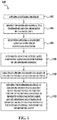
- FIG. 1 An example of the 3D printing method 100 is depicted in Fig. 1 . It is to be understood that each of the steps of the method 100 shown in Fig. 1 will be discussed in detail herein, and in some instances, Figs. 2A through 2F and Figs. 3 and 4 will be discussed in conjunction with Fig. 1 .
- the method 100 includes applying a sinterable material.
- An example of this step 102 is shown in cross-section at Fig. 2A .
- one layer 10 of the sinterable material 16 has been deposited, as will be discussed in more detail below.
- the sinterable material 16 may be a powder, a liquid, a paste, or a gel.
- sinterable material 16 include semi-crystalline thermoplastic materials with a wide processing window of greater than 5°C (i.e., the temperature range between the melting point and the re-crystallization temperature).
- Some specific examples of the sinterable material 16 include polyamides (e.g., nylon 11, nylon 12, nylon 6, nylon 8, nylon 9, nylon 66, nylon 612, nylon 812, nylon 912, etc.).
- Other specific examples of the sinterable material 16 include polyethylene, polyethylene terephthalate (PET), and amorphous variation of these materials.
- PET polyethylene terephthalate
- suitable sinterable materials 16 include polystyrene, polyacetals, polypropylene, polycarbonate, and blends of any two or more of the polymers listed herein. Core shell polymer particles of these materials may also be used.
- the sinterable material 16 includes similarly sized polymer particles (e.g., particles of all the same size). In another example, the sinterable material 16 includes differently sized polymer particles. For example, the sinterable material 16 may include particles having two or more different sizes. In the example shown in Fig. 2A , the sinterable material 16 includes a plurality of polymer particles 16A, 16B, 16C containing at least three different particle sizes. While polymer particles 16A, 16B, 16C of three different sizes are shown in Fig. 2A , it is to be understood that any additional number of particle sizes may be added.
- the average size of the first polymer particle 16A is larger than the average size of the second polymer particle 16B, and the average size of the second polymer particle 16B is larger than the average size of the third polymer particle 16C.
- size refers to the diameter of a spherical particle, or the average diameter of a non-spherical particle (i.e., the average of multiple diameters across the particle).
- the average size of each of the first, second, and third particles 16A, 16B, 16C ranges from 5 ⁇ m to about 100 ⁇ m.
- the average size of the first polymer particle 16A may be greater than 50 ⁇ m
- the average size of the second polymer particle 16B may be between 10 ⁇ m and 30 ⁇ m
- the average size of the third polymer particle 16C may be equal to or less than 10 ⁇ m.
- the shape of the particles 16A, 16B, 16C may also be the same or different.
- the particles 16A, 16B, 16C have spherical or near-spherical shapes.
- Particles 16A, 16B, 16C that have a sphericity of >0.84 are considered to be spherical or near-spherical in the examples disclosed herein.
- any particles 16A, 16B, 16C having a sphericity of ⁇ 0.84 are non-spherical.
- One or more of the particles 16A, 16B, 16C may also be physically modified, so that the surface topography of the particles 16A, 16B, 16C is altered, and/or chemically modified.
- sinterable material 16 may include, in addition to polymer particles 16A, 16B, and/or 16C, a charging agent, a flow aid, or combinations thereof.
- Charging agent(s) may be added to suppress tribo-charging.
- suitable charging agent(s) include aliphatic amines (which may be ethoxylated), aliphatic amides, quaternary ammonium salts (e.g., behentrimonium chloride or cocamidopropyl betaine), esters of phosphoric acid, polyethylene glycol esters, or polyols.
- Some suitable commercially available charging agents include HOSTASTAT® FA 38 (natural based ethoxylated alkylamine), HOSTASTAT® FE2 (fatty acid ester), and HOSTASTAT® HS 1 (alkane sulfonate), each of which is available from Clariant Int. Ltd.).
- the charging agent is added in an amount ranging from greater than 0 wt% to less than 5 wt% based upon the total wt% of the polymer particles.
- Flow aid(s) may be added to improve the coating flowability of the sinterable material 16.
- Flow aid(s) may be particularly desirable when the particles 16A, 16B, and/or 16C are less than 25 ⁇ m in size. The flow aid improves the flowability of the sinterable material 16 by reducing the friction, the lateral drag, and the tribocharge buildup (by increasing the particle conductivity).
- Suitable flow aids include tricalcium phosphate (E341), powdered cellulose (E460(ii)), magnesium stearate (E470b), sodium bicarbonate (E500), sodium ferrocyanide (E535), potassium ferrocyanide (E536), calcium ferrocyanide (E538), bone phosphate (E542), sodium silicate (E550), silicon dioxide (E551), calcium silicate (E552), magnesium trisilicate (E553a), talcum powder (E553b), sodium aluminosilicate (E554), potassium aluminium silicate (E555), calcium aluminosilicate (E556), bentonite (E558), aluminium silicate (E559), stearic acid (E570), or polydimethylsiloxane (E900).
- the flow aid is added in an amount ranging from greater than 0 wt% to less than 5 wt% based upon the total wt% of the particles 16A, 16B
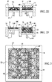
- a printing system 12 for forming the 3D object includes a supply bed 14 (including a supply of the sinterable material 16), a delivery piston 18, a roller 20, a fabrication bed 22 (having a contact surface 25), and a fabrication piston 24.
- Each of these physical elements may be operatively connected to a central processing unit (not shown) of the printing system 12.
- the central processing unit e.g., running computer readable instructions stored on a non-transitory, tangible computer readable storage medium
- the data for the selective delivery of the sinterable material 16, the coalescent agent, etc. may be derived from a model of the 3D object to be formed.
- the delivery piston 18 and the fabrication piston 24 may be the same type of piston, but are programmed to move in opposite directions.
- the delivery piston 18 may be programmed to push a predetermined amount of the sinterable material 16 out of the opening in the supply bed 14 and the fabrication piston 24 may be programmed to move in the opposite direction of the delivery piston 18 in order to increase the depth of the fabrication bed 22.
- the delivery piston 18 will advance enough so that when the roller 20 pushes the sinterable material 16 into the fabrication bed 22 and onto the contact surface 25, the depth of the fabrication bed 22 is sufficient so that a layer 10 of the sinterable material 16 may be formed in the bed 22.
- the roller 20 is capable of spreading the sinterable material 16 into the fabrication bed 22 to form the layer 10, which is relatively uniform in thickness.
- the thickness of the layer 10 ranges from about 90 ⁇ m to about 110 ⁇ m, although thinner or thicker layers may also be used.
- roller 20 may be replaced by other tools, such as a blade that may be desirable for spreading different types of powders, or a combination of a roller and a blade.
- the layer 10 of the sinterable material 16 is deposited in the fabrication bed 22, the layer 10 is exposed to heating (as shown at reference number 104 in Fig. 1 and in Fig. 2B ). Heating is performed to pre-heat the sinterable material 16, and thus it is desirable that the heating temperature be below the melting point of the sinterable material 16. As such, the temperature selected will depend upon the sinterable material 16 that is used. As examples, the heating temperature may be from about 5°C to about 50°C below the melting point of the sinterable material. In an example, the heating temperature ranges from about 50°C to about 350°C. In another example, the heating temperature ranges from about 150°C to about 170°C. In another example, some or all of the pre-heating may be performed while the sinterable material 16 is still on the supply bed 14.
- Pre-heating the layer 10 of the sinterable material 16 may be accomplished using any suitable heat source that exposes all of the sinterable material 16 in the fabrication bed 22 or the supply bed 14 to the heat.
- the heat source include a thermal heat source or a light radiation source.
- the coalescent agent is selectively applied on a portion of the sinterable material 16 in the layer 10, as shown at reference number 106 in Fig. 1 and in Fig. 2C .
- the coalescent agent 28 may be dispensed from an inkjet printhead 26. While a single printhead is shown in Fig. 2C , it is to be understood that multiple printheads may be used that span the width of the fabrication bed 22.
- the printhead 26 may be attached to a moving XY stage or a translational carriage (neither of which is shown) that moves the printhead 26 adjacent to the fabrication bed 22 in order to deposit the coalescent agent 28 in desirable area(s).
- the printhead 26 may be programmed to receive commands from the central processing unit and to deposit the coalescent agent 28 according to a pattern of a cross-section for the layer of the 3D object that is to be formed.
- the cross-section of the layer of the object to be formed refers to the cross-section that is parallel to the contact surface 25.
- the printhead 26 selectively applies the coalescent agent 28 on those portion(s) 44 of the layer 10 that are to be fused to become the first layer of the 3D object.
- the coalescent agent 28 will be deposited in a square pattern or a circular pattern (from a top view), respectively, on at least a portion 44 of the layer 10 of the sinterable material 16. In the example shown in Fig. 2C , the coalescent agent 28 is deposited in a square pattern on the portion 44 of the layer 10 and not outside the portion 44.
- suitable coalescent agents 28 are water-based dispersions including a radiation absorbing binding agent (i.e., an active material).
- the active agent may be an infrared light absorber, a near infrared light absorber, or a visible light absorber.
- the coalescent agent 28 may be an ink-type formulation including carbon black as the active material.
- An example of this ink-type formulation is commercially known as CM997A available from Hewlett-Packard Company.
- examples of inks including visible light enhancers as the active agent are dye based colored ink and pigment based colored ink.
- pigment based colored inks include the commercially available inks CE039A and CE042A, available from Hewlett-Packard Company.
- the aqueous nature of the coalescent agent 28 enables the coalescent agent 28 to penetrate, at least partially, into the layer 10 of the sinterable material 16.
- the sinterable material 16 may be hydrophobic, and the presence of a co-solvent and/or a surfactant in the coalescent agent 28 may assist in obtaining desirable wetting behavior.
- coalescent agent 28 may be selectively applied to form the layer of the 3D object, or multiple coalescent agents 28 may be selectively applied to form the layer of the 3D object.
- the modifying agent Prior to, concurrently with, or after the coalescent agent 28 is/are selectively applied on the desired portion(s) 44, the modifying agent is selectively applied on different portion(s) of the sinterable material 16, as shown at reference numeral 110 in Fig. 1 .
- An example of the selective application of the modifying agent is schematically shown in Fig. 2D , where reference numeral 29 represents the modifying agent and reference numeral 42 represents the other portions of the sinterable material 16 to which the modifying agent 29 is selectively applied.
- the modifying agent 29 acts as a coolant, which effectively removes energy and keeps the sinterable material 16 at a temperature that prevents curing or retards the sintering, melting, fusing, and/or curing of the sinterable material 16.
- the method 100 further includes determining how to selectively apply the modifying agent 29. This is shown at reference numeral 108 in Fig. 1 .
- the determination as to how to selectively apply the modifying agent 29 may include determining where to apply the modifying agent 29 and/or determining how much of the modifying agent 29 to apply. These determinations may be made using a thermal diffusion characteristic of the sinterable material 16, a layer to be formed of the sinterable material 16 (i.e., the sintered layer or part), or combinations thereof.
- the thermal diffusion characteristic may be a time scale/characteristic time of thermal diffusion, a length scale/characteristic length of thermal diffusion, a temperature profile, and/or an energy profile.
- Characteristic times and lengths refer to the approximate time or distance required for a system to recover from a perturbation. They are often defined as the time or distance for a perturbation to be reduced to 1/e (-37%) of the initial perturbation. In practice, they are often used to mean the time or distance over which a perturbation has a significant effect.
- the time scale of thermal diffusion generally refers to the time it takes for the sinterable material to stabilize (approach its equilibrium value) in temperature after energy has been added or removed from an adjoining area of material.
- the length scale of thermal diffusion generally refers to the distance from the part edge or build surface that experiences a significant temperature increase due to the presence of the hot sintered material. As examples, the distance may be horizontal or vertical with respect to the location of the sintered material.
- Examples of a significant temperature change or increase include i) a temperature rise of about 25% of the difference between the sintered part/layer temperature and the surrounding sinterable material temperature, or ii) 25% of the difference between the normal temperature of the surrounding sinterable material 16 and the melting temperature of the sinterable material 16.
- the time and/or length scales of thermal diffusion may be empirically measured, or derived from respective thermal diffusion coefficients or temperature differences in the system.
- the thermal diffusion coefficients may themselves be empirically determined or estimated from values of similar materials or by chemical modeling methods.
- the temperature and or energy profile generally refers to temperature and/or energy differences exhibited by the sinterable material 16 or sintered part/layer with or without an agent 28 and/or 29 applied thereon. As examples, these differences may be observed before radiation exposure (e.g., due to modifying agent evaporation) or after radiation exposure (e.g., due to energy migration).
- the temperature profile and/or energy profile may be generated using the thermal model, or may be an estimation of a temperature or energy profile. As will be described in more detail below, the estimation of the temperature or energy profile may be based upon manipulating the image data used to form the 3D part layers. Calculating the local variation from mean values of the surrounding region provides a rough estimation of the temperature and/or energy differences in the sintered layer/part where coalescence agent 28 is applied and not applied.
- the appropriate quantity and/or position of the modifying agent 29 may be determined using a time-dependent thermal model of the sintering process.
- the thermal model itself may be used to directly calculate the modifying agent quantity and/or identify the modifying agent position.
- the thermal model is used to generate a temperature or energy profile, which can be used by a correction algorithm to generate a pattern (e.g., location and/or quantity) for applying the modifying agent 29.
- one or more thermal models may be used to identify typical time and/or length scales of thermal diffusion.
- the typical length scale and/or time scale may then be used to calculate the modifying agent quantity and/or determine the modifying agent position, without requiring full modeling of the exact geometry of the 3D object to be formed.
- the appropriate quantity and/or position of the modifying agent 29 may be determined empirically.
- the thermal model may be generated using a computational modeling method.
- the computational modeling method is performed by a computer (including hardware components, such as a processor) running/executing computer readable instructions that are stored on a non-transitory, tangible computer readable medium.
- An example of the computational modeling software is Abaqus FEA version 6.13.
- the computer readable medium may include any one of many physical media such as, for example, electronic, magnetic, optical, electromagnetic, or semiconductor media. More specific examples of suitable computer readable media include hard drives, a random access memory (RAM), a read-only memory (ROM), an erasable programmable read-only memory (EPROM), or a portable CD, DVD, or flash drive.
- the computational modeling method or any of the computer-based methods for determining how to apply the modifying agent 29 may be virtualized and configured in a Cloud Computer (i.e., in an Internet-based computing environment).
- the computer equipment may be accessed as a Cloud platform service, or PaaS (Platform as a Service), utilizing Cloud infrastructure rather than hosting computer equipment at a physical building.
- the Cloud infrastructure known as laaS (Infrastructure as a Service), typically utilizes a platform virtualization environment as a service, which may include components such as the processor, database, server, and other computer equipment.
- the computer receives characteristics (e.g., as inputs from a user) that are sufficient to build the thermal model. These characteristics relate to the sinterable material 16 being modeled (e.g., the type of powder, thermal conductivity at different temperatures, heat capacity, and density), the number of layers, the thickness of the layers, the type of coalescence agent 28 being modeled, a set temperature of the fabrication bed 22, and the time for building a particular layer.
- the density, heat capacity, and the thermal diffusivity are provided for both the unsintered sinterable material 16 and the sintered material.
- the heat capacity change between the unsintered sinterable material 16 and the sintered material may be largely due to the density change between the materials, and thus a single heat capacity value may be adequate.
- characteristics that may be input to the computer are the energy released when the layer solidifies from a molten state, the temperature at which the sinterable material 16 and coalescent agent 28 are delivered to the fabrication bed 22, and/or the expected energy inputs or losses from the edge surface(s) of the build volume.
- any or all of these parameters/characteristics may vary with temperature. It may be desirable to include the temperature dependent behavior, for example, if the parameters change more than 10% within the temperature range experienced during the build process.
- the entered characteristics may also include the differences in temperature, specific heat capacity, and thermal diffusivity between the sinterable material 16 in the portion 44 (to be cured) and the portion 42 (not to be cured).
- a suitable input may describe the difference in radiation converted to heat by the non-sintered regions (e.g., portion 42) versus the portion(s) 44 with coalescent agent 28 that will convert more of the radiation to heat.
- This input may be an empirical measurement of the temperature difference between cure/sintered portion(s) 44 and the uncured/unsintered portion(s) 42.
- Other general characteristics may include a higher specific heat capacity and a lower thermal diffusivity at the portion(s) 42 than at the portion(s) 44.
- thermal model of the layer or object All of these characteristics are used by the computer (running a suitable software program) to build a thermal model of the layer or object.
- a finite element analysis or other modeling technique may be used to identify the thermal gradients that develop around the layer or object over a time scale of interest.
- the time scale of interest is the time required to build one or several layers.
- the thermal gradients that develop around the layer/part over the time scale of interest identify the length scale of thermal diffusion for a particular thermal model.
- the time scale of thermal diffusion may be determined by generating a thermal model with different numbers of part layers that are to be formed, and identifying long the model must be run after the addition of a material layer for convergence of the thermal model to stable predictions at a particular layer.
- the temperatures in the vicinity of the layer or object while it is being fabricated can be estimated based upon the model (e.g., using the thermal gradient(s)).
- the thermal model is used to determine the location and timing of heat flows in and around the layer or object being constructed.
- the excess temperature ( ⁇ T) of the sintered material 16 in the portion 42 (where curing is not desirable) that is above the set temperature of the fabrication bed 22 represents excess energy evolved from the layer or object.
- the excess temperature may be determined by subtracting the set temperature of the fabrication bed from the temperature of the sintered material 16 in the portion 42 according to the thermal model or an empirical measurement (taken using a high resolution temperature measuring device, such as an IR camera).
- the excess energy for the entire portion 42 can be identified. As such, a map of excess energy around the layer or object can be generated by this method.
- the excess energy is equivalent to a quantity of energy to be removed (i.e., removed energy) by the modifying agent 29.
- the excess energy can be converted to a quantity of the modifying agent 29 that is appropriate to remove this quantity of energy.
- a map of the desired quantities of modifying agent 29 around the layer or object can be generated. As such, with this example, both the position and the quantity of the modifying agent 29 to be used may be determined.
- the conversion from excess/removed energy to modifying agent quantity may be accomplished using the specific heat capacity (Cp MA ) of the modifying agent 29 to raise its temperature from the application temperature (T app-MA ) to the boiling point (T boil-MA ), plus the heat of vaporization (H vap-MA ) of the modifying agent 29.
- Cp MA specific heat capacity
- H vap-MA heat of vaporization
- the application temperature (T app-MA ) of the modifying agent 29 may be room temperature (from about 18°C to about 22°C), a temperature controlled by the printhead 26' (see Fig. 2D ) or other application device (e.g., a warming or operating temperature of an inkjet printhead), or a typical temperature that the modifying agent 29 reaches as it is delivered into the heated fabrication bed 22 of the system 12.
- the sum of the heating and vaporization energy terms multiplied by the volume of the modifying fluid 29 is equal to the total energy that the modifying agent 29 will remove from the system (i.e., the removed energy).
- the modifying agent 29 evaporates and removes energy from the sinterable material 16. Evaporation may be on the order of a few tenths of a second, which may result in significant removal before the application of the curing energy (i.e., radiation R, see Fig. 2E ). This may create a cold region to which energy will migrate over time. In other words, energy may diffuse back into the portion(s) 42 that were cooled by the modifying agent 29 (resulting in a loss of local cooling). This secondary migration of energy (in terms of amount) may be estimated by modeling or empirical methods. Then, the quantity of energy to be removed (i.e., removed energy in equation 3 above) may be increased by this amount to compensate for this effect.
- the curing energy i.e., radiation R, see Fig. 2E
- the thermal model could be allowed to run for a desired delay time after the application of modifying agent 29.
- the modifying agent 29 may be incorporated in the model as a simple removal of energy at an instant in time, or as a sub-model involving evaporation and other fluid behaviors.
- the temperature measurements described in the following empirical method could be made following a delay after the application of rad iation.
- the temperature change refers to a difference between the temperature of the sinterable material 16 (without having any coalescent agent 28 or modifying agent 29 thereon) after being exposed to radiation and the temperature of the sinterable material 16 (having modifying agent 29 thereon) after being exposed to radiation.
- any temperature measurements may be performed with any suitable temperature device, such as an infrared (IR) camera, an IR temperature sensor, or low mass thermocouple.
- the table may be constructed by applying different quantities of the modifying agent 29 on respective areas of the sinterable material 16, and applying no modifying agent 29 on one area of the sinterable material 16.
- the entire sinterable material 16 may then be exposed to radiation.
- the area with no modifying agent 29 exposed to radiation is referred to as a reference area, and the areas with the different quantities of the modifying agent 29 exposed to radiation are referred to as test areas.
- the temperature of the reference area and the test areas may be measured.
- Each test area that received modifying agent after receiving radiation should have a lower temperature than the reference area. For a particular test area, the temperature reduction compared to the reference area is the effect of the associated quantity of modifying agent.
- the temperature changes may be calculated and correlated with the different quantities of the modifying agent 29 that are used to generate the table.
- the table may be referenced to determine the quantity of modifying agent 29 to use to effect a desired temperature change.
- the length scale of thermal diffusion may be empirically determined.
- a test layer/part is used.
- the test layer/part is made up of the same sinterable material 16 and same coalescent agent 28 that is to be used for the actual 3D object/layer.
- the coalescent agent 28 may be applied in a simple geometry, such as a square, or in geometry similar to actual 3D objects.
- the size of the test part should be large compared with the determined length scale of thermal diffusion, e.g., at least three times the size. In an example, a half inch may be a sufficient size. However, if the determined length scale is larger than 1/3 the object size, the test should be redone using a larger test part size.
- No modifying agent 29 is used for the test layer/part.
- the test layer/part After application of the coalescent agent 28 and exposure to radiation, the test layer/part is formed.
- the position of the coalescent material 28 when forming the test layer/part is compared to the actual extent of material 16 sintering in the test layer/part. During this comparison, the test layer/part is examined for any undesirable sintered material located beyond/outside the edge boundary of the applied coalescent material 28.
- the length of the undesirable sintered material is measured. This value, or this value multiplied by a scalar correction factor, is the estimated length scale that can be used in other examples. If the actual 3D object geometry was used, the region of undesirable sintered material can be used to estimate the location for the modifying agent 29 during formation of the actual 3D object/layer.
- the coalescent agent 28 When subsequently forming the actual 3D object/layer, the coalescent agent 28 may be applied in the same position and the modifying agent 29 may be applied along the estimated length scale.
- the use of the modifying agent 29 close to the edge boundary 27 may reduce the temperature of the sinterable material 16 within the portion(s) 42 at the edges of the layer to be formed, but may also reduce the quality of sintering or melting within the portion(s) 44 along the edge boundary 27. This energy loss within the cross-section of the layer may be compensated for by increasing the quantity of the coalescent agent 28 within the portion(s) 44.
- the thermal model may also predict that the interior of a layer/part is too hot (i.e., excess energy is present).
- This energy increase within the cross-section of the layer/part may be compensated for by decreasing the quantity of the coalescent agent 28 within the portion(s) 44 and/or increasing a quantity of the modifying agent 29 within the portion(s) 44.
- the amount of modifying agent 29 to add may be calculated using equation 3, except in this instance the removed energy is the excess energy at the particular location within the cross-section of the layer/part.
- the increased or decreased quantity of the coalescent agent 28 may be determined in an analogous fashion to determining how much modifying agent 29 to selectively apply.
- the delta temperature values of the thermal model may be converted to an energy quantity, and using a modeled or empirical table of coalescent agent quantity versus energy absorbed, the additional quantity of coalescent agent 28 may be determined.
- the quantity of coalescent agent 28 required will have a linear relationship with the desired temperature change.
- the absorption efficiency may be reduced, and additional coalescent agent 28 may be needed to effect the desired change.
- This may be modeled or empirically determined by comparing temperatures after radiation is applied to portions of the sinterable material 16 covered with different quantities of coalescing agent.
- a model based solution may need to incorporate the cooling effect of evaporating any volatile solvents dispensed as part of the coalescent agent 28, in addition to the absorption behavior of the coalescent agent 28, and radiative or convective losses from the surface of the fabrication bed 22.
- the computer may include a correction algorithm. Using the correction algorithm, a modified image may be generated to correct for the thermal diffusion effects for each layer image of the 3D object to be formed.
- the correction algorithm utilizes 3D shape information for the layer image and a temperature/energy profile associated with the 3D shape to generate a pattern (including location and/or quantity information) for applying the modifying agent 29.
- the 3D shape information may include information about one layer, several layers, or the entire part, and may also include value(s) that is/are indicative of the selective application of the coalescent agent 28. For example, there may be a spatially varying quantity of coalescent agent 28 that is used in the thermal model or used in the manipulation of the 3D shape information.
- the 3D shape information may be supplied to the thermal model and the temperature/energy profile may be automatically generated.
- manipulation of the 3D shape information (described below) may be used to generate an estimation of the temperature/energy profile (in the form of a map of local temperature/energy variation) without using a thermal model.
- the map of local temperature/energy variation in the build region can be constructed from the 3D layer image based on a spatial averaging technique.
- the original layer image is composed of, or can be converted into data with positive values describing portion(s) 44 that should receive coalescent agent 28, and a value of zero describing portion(s) 42 not receiving the coalescent agent 28. It is to be understood however, that the values may be switched if desirable.
- value conventions are used for the purposes of clarity in this example. It is to be understood that other value conventions and math operations could be employed to achieve the intended result.
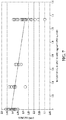
- the radius of the layer image over which an average may be taken may be determined by the characteristic length of thermal diffusion found in the thermal model or by empirical measurement of excess part growth. This empirical measurement may be performed by building parts of nominal lengths using coalscent agent 28, and plotting the dimensional error after radiation exposure (when no modifying agent 29 is used) versus the nominal size. In this example, the intercept of the best fit line with the Y axis (0 length part) should be approximately the characteristic length. This empirical measurement may also be performed as previously described for the length scale (e.g., with the test layer/part).
- a rough map of local temperature/energy content can be calculated at each location (i.e. pixel) by averaging the values of all the pixels within the radius of that location. Averaging may be accomplished using a Gaussian averaging function, or some other suitable averaging function.
- the difference between the original pixel value and the averaged value of all pixels within the specified radius indicates the amount of energy imbalance that may be corrected for using the modifying agent 29 at that pixel location. More particularly, when the averaged pixel value exceeds the actual pixel value (e.g., a negative difference), this indicates that cooling by the modifying agent 29 is desirable.
- the modifying agent 29 should not be used, or that an additional quantity of coalescent agent 28 may be applied to the location.
- the positive difference value may be directly added to the original pixel value to modify the coalescent agent 28 quantity, multiplied by a scalar adjustment factor, or used as the index in a look up table to find a quantity to add to the original pixel value.
- the negative difference value may be used directly, multiplied by a scalar adjustment factor, or used as the index in a look up table to find a suitable quantity. From the difference values, the pattern for applying the coalescent agent 28 and/or modifying agent 29 may be produced.
- the correction algorithm may result in both positive and negative differences at different portions of the layer image.
- the quantities for both the modifying agent 29 and the coalescent agent 28 may be adjusted.
- the use of the modifying agent 29 may not be desirable.
- the final corrected image (i.e., the result of averaged image subtraction or the image modified by thermal model results) may be halftoned, i.e., converted into a spatial pattern of dots corresponding to the intensity information in the corrected image.
- the correction algorithm may be desirable to perform the correction algorithm by averaging multiple layers of the 3D object geometry, rather than a single layer.
- the modifying agent 29 is selectively applied in the desired portion(s) 42, or in some instances in portion(s) 44, of the sinterable material 16 (as shown at reference numeral 110 in Fig. 1 and in Fig. 2D ).
- the modifying agent 29 includes a surfactant, a co-solvent, water, and optionally a biocide.
- the modifying agent 29 consists of these components, and no other components. It has been found that this particular combination of components effectively reduces or prevents coalescence bleed, in part because the water and co-solvent provide evaporative cooling to the sinterable material 16 in proximity thereof (e.g., in thermal contact therewith). It is believed that evaporation of 1.3 milligrams per cm 2 of the modifying agent 29 can remove up to 3 Joules of energy per cm 2 of the sinterable material 16. This energy loss is enough to keep the sinterable material 16 from heating and curing (e.g., which may require 4 to 5 Joules per cm 2 per 100 micron layer of sinterable material 16).
- the co-solvent that is used in the modifying agent 29 has a lower thermal diffusivity than water. As such, the co-solvent exhibits less heat transfer than water. This characteristic renders the modifying agent 29 as being capable of reducing the energy flow from the sintered material to the unsintered surroundings having the modifying agent 29 thereon. As such, the modifying agent 29 aids in reducing undesired migration of energy.
- the modifying agent 29 disclosed herein can effectively reduce or prevent curing of the sinterable material 16 when the sintering material 16 is in thermal contact with the modifying agent 29.
- the total amount of co-solvent present in the modifying agent 29 ranges from about 5.0 wt% up to 30 wt% with respect to the total weight of the modifying agent 29.
- suitable co-solvents at least have a lower thermal diffusivity than water.
- the modifying agent 29 also includes the surfactant.
- the type and amount of surfactant may be selected so that a contact angle with a contact line of the sinterable material 16 is less than 90°. In some instances, the contact angle may be less than 45°, which may be desirable to ensure wetting of the sinterable material 16 with the modifying agent 29.
- the components of the modifying agent 29 may be mixed together, and then the amount of surfactant may be adjusted to achieve the desirable contact angle. It has been found that the suitable amount of surfactant may vary depending in part upon the strength of the surfactant and/or whether a combination of surfactants is used. In an example, the surfactant amount may be up to about 1.5 wt% with respect to the total weight of the modifying agent 29.
- Suitable surfactants include a self-emulsifiable, nonionic wetting agent based on acetylenic diol chemistry (e.g., SURFYNOL® SEF from Air Products and Chemicals, Inc.), a perfluoro-based ethoxylated nonionic fluorosurfactant (CHEMGUARD® S-550-100 from Tyco Fire & Security GMBH LLC), a nonionic fluorosurfactant (e.g., CAPSTONE® fluorosurfactants from DuPont, previously known as ZONYL FSO), and combinations thereof.
- a self-emulsifiable, nonionic wetting agent based on acetylenic diol chemistry e.g., SURFYNOL® SEF from Air Products and Chemicals, Inc.
- CHEMGUARD® S-550-100 from Tyco Fire & Security GMBH LLC
- nonionic fluorosurfactant e.g.,
- the modifying agent 29 also includes, in some instances, the biocide.
- the biocide When part of the modifying agent 29, the biocide is present in an amount ranging from about 0.01 wt% to about 0.2 wt% with respect to the total weight of the modifying agent 29.
- An example of a suitable biocide is an aqueous solution of 1,2-benzisothiazolin-3-one (e.g., PROXEL® GXL from Arch Chemicals, Inc.).
- the balance of the modifying agent 29 is water.
- the amount of water may vary depending upon the amounts of surfactant, co-solvent, and, in some instances, biocide that are included. In an example, the amount of water ranges from about 70 wt% to about 95 wt% of the total weight of the modifying agent 29.
- the modifying agent 29 may be selectively applied in a manner similar to the coalescent agent 28. In an example, the modifying agent 29 may be applied at the same time that the coalescent agent 28 is dispensed, using a single pass or using multiple passes. In another example, the modifying agent 29 may be applied before or after the coalescent agent 28 is dispensed.
- the modifying agent 29 may be dispensed from an inkjet printhead 26'. While a single printhead is shown in Fig. 2D , it is to be understood that multiple printheads may be used that span the width of the fabrication bed 22.
- the printhead 26' may be attached to a moving XY stage or a translational carriage (neither of which is shown) that moves the printhead 26' adjacent to the fabrication bed 22 in order to deposit the modifying agent in desirable area(s).
- the printhead 26' may be programmed to receive commands from the central processing unit and to deposit the modifying agent 29 in the desired portion(s) 44 and/or 42.
- the coalescent agent 28 may be selectively applied according to the pattern of the cross-section (which is parallel to the contact surface 25) for the layer of the 3D object, and the modifying agent 29 may be selectively applied along at least part of an edge boundary 27 of that cross-section.
- Fig. 2D side cross-sectional view of the system 12
- Fig. 3 top view of the sinterable material 16 in the fabrication bed 22.
- the shape of the 3D object layer to be formed is a rectangular prism, and the pattern of the cross-section that is parallel to the contact surface 25 is a square or rectangle having edge boundary 27.
- the sinterable material 16 within the edge boundary 27 is the portion 44 upon which the coalescent agent 28 is selectively applied.
- the sinterable material 16 positioned between the edge boundary 27 and the edges of the fabrication bed 22 is outside the pattern of the cross-section for the layer to be formed, and thus is the portion 42 upon which the modifying agent 29 is selectively applied.
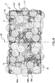
- FIG. 4 a front perspective view of some of each of the two portions 42 and 44 is depicted.
- the view in Fig. 4 illustrates some of the sinterable material 16 after the coalescent agent 28 and modifying agent 29 are applied thereon.
- the coalescent agent 28 may penetrate into at least some of the voids 31 between the particles 16A, 16B, 16C of the sinterable material 16 within the portion 44.
- the modifying agent 29 may penetrate into at least some of the voids 31' between the particles 16A, 16B, 16C of the sinterable material 16 within the portion 42 outside of the edge boundary 27.
- the coalescent agent 28 and/or modifying agent 29 may not penetrate into the voids 31, 31', but may spread out over the exposed surface of the layer 10 of the sinterable material 16.
- the modifying agent 29 is capable of preventing curing (fusing, sintering, etc.) of the portion 42 of the sinterable material 16, while the coalescent agent 28 is capable of enhancing curing (fusing, sintering, etc.) of the portion 44 of the sinterable material 16.
- the coalescent agent 28 may be selectively applied according to the pattern of the cross-section (which is parallel to the contact surface 25) for the layer of the 3D object, but the amount may be lowered to reduce the amount of energy in the desired areas.
- the coalescent agent 28 may be selectively applied according to the pattern of the cross-section (which is parallel to the contact surface 25) for the layer of the 3D object, and the modifying agent 29 may be selectively applied within at least a portion of that cross-section in order to reduce the amount of energy in the desired areas.
- the modifying agent 29 may be applied to all or some of the portion 44 of the sinterable material 16 upon which the coalescent agent 28 is applied.
- the modifying agent 29 may be applied at or near the center of the portion 44 of the sinterable material 16 that exhibits a higher temperature during curing, and may not be applied near the edge boundary 27 of the portion 44 of the sinterable material 16.
- the entire layer 10 of the sinterable material 16 is exposed to radiation R. This is shown at reference numeral 112 of Fig. 1 and in Fig. 2E .
- the radiation R is emitted from a radiation source 30, such as an IR, near-IR, UV, or visible curing lamp, IR, near-IR, UV, or visible light emitting diodes (LED), or lasers with specific wavelengths.
- the radiation source 30 used will depend, at least in part, on the type of coalescent agent 28 that is used.
- the radiation source 30 may be attached, for example, to a carriage that also holds the printhead(s) 26, 26'. The carriage may move the radiation source 30 into a position that is adjacent to the fabrication bed 22.
- the radiation source 30 may be programmed to receive commands from the central processing unit and to expose the layer 10, including the coalescent agent 28 and modifying agent 29, to radiation R.
- the length of time the radiation R is applied for, or energy exposure time may be dependent, for example, on one or more of: characteristics of the radiation source 30; characteristics of the sinterable material 16; and/or characteristics of the coalescent agent 28.
- the time between selective application of the coalescent agent 28 and the modifying agent 29 and exposure to radiation may range anywhere from 0.05 seconds to about 6 seconds.
- the time between application and radiation exposure may be decreased and/or the amount of modifying agent 29 may be increased.
- Making time and/or quantity adjustments ensures that the temperature of the selected portions remains depressed for a time sufficient to suppress curing in the portion(s) 42 while curing takes place in the portion(s) 44. This is desirable because when the portion(s) 42 are colder than their surroundings due to evaporation, energy migration into the portion(s) 42 may occur over time.
- the coalescent agent 28 enhances the absorption of the radiation R, converts the absorbed radiation to thermal energy, and promotes the transfer of the thermal energy to the sinterable material 16 in proximity thereof (i.e., the sinterable material 16 within thermal contact of the coalescence agent 28).
- the coalescent agent 28 sufficiently elevates the temperature of the sinterable material 16 in the portion 44 above the melting point(s), allowing curing (e.g., sintering, binding, fusing, etc.) of the particles 16A, 16B, 16C to take place.
- portions 42 of the sinterable material 16 that do not have the coalescent agent 28 applied thereto but do have the modifying agent 29 applied thereto do absorb some energy.
- the modifying agent 29 may diffuse the absorbed energy to the adjacent sinterable material 16 more slowly, and evaporation of the modifying agent 29 removes energy.
- the particles 16A, 16B, 16C within the portion(s) 42 generally do not exceed the melting point(s) of the particles 16A, 16B, 16C and do not cure.
- Exposure to radiation R forms one layer 32 of the 3D object 40 (see Fig. 2F ) to be formed.
- Steps 102 through 112 of Fig. 1 may be repeated as many times as desirable to create subsequent layers 34, 36, 38 ( Fig. 2F ) and to ultimately form the 3D object 40.
- heat absorbed during the application of energy from a portion of the sinterable material 16 on which coalescent agent 28 has been delivered may propagate to a previously solidified layer, such as layer 32, causing at least some of that layer to heat up above its melting point. This effect helps create strong interlayer bonding between adjacent layers of the 3D object 40.
- Fig. 2F illustrates one example of the 3D object 40 in the fabrication bed 22. It is to be understood, however, that the subsequently formed layers 34, 36, 38 may have any desirable shape and/or thickness and may be the same as or different from any other layer 32, 34, 36, 38 depending upon the size, shape, etc. of the 3D object 40 that is to be formed.
- the delivery piston 18 is pushed closer to the opening of the delivery bed 14, and the supply of the sinterable material 16 in the delivery bed 14 is diminished (compared, for example, to Fig. 2A at the outset of the method).
- the fabrication piston 24 is pushed further away from the opening of the fabrication bed 22 in order to accommodate the subsequent layer(s) of sinterable material 16, the selectively applied coalescent agent 28, and the selectively applied modifying agent 29. Since at least some of the sinterable material 16 remains uncured after each layer 32, 34, 36, 38 is formed, the 3D object 40 is at least partially surrounded by the uncured sinterable material 16 and modifying agent 29 in the fabrication bed 22.
- the 3D object 40 When the 3D object 40 is complete, it may be removed from the fabrication bed 22, and the uncured sinterable material 16 and modifying agent 29 may be separated from one another. This may be accomplished by washing with water. The uncured sinterable material 16 may be washed and then reused.
- the system 12' includes a central processing unit 46 that controls the general operation of the additive printing system 12'.
- the central processing unit 46 may be a microprocessor-based controller that is coupled to a memory 50, for example via a communications bus (not shown).
- the memory 50 stores the computer readable instructions 48.
- the central processing unit 46 may execute the instructions 48, and thus may control operation of the system 12' in accordance with the instructions 48.
- the printing system 12' includes a coalescent agent distributor 26 to selectively deliver coalescent agent 28 to portion(s) 44 of the layer (not shown in this figure) of sinterable material 16 provided on a support member 58.
- the printing system 12' also includes a modifying agent distributor 26' to selectively deliver modifying agent 29 to other portion(s) 42 and/or the portion(s) 44 of the layer (not shown in this figure) of sinterable material 16 provided on a support member 58.
- the support member 58 has dimensions ranging from about 10 cm by 10 cm up to about 100 cm by 100 cm, although the support member 58 may have larger or smaller dimensions depending upon the 3D object 40 that is to be formed.
- the central processing unit 46 controls the selective delivery of the coalescent agent 28 and the modifying agent 29 to the layer of the sinterable material 16 in accordance with delivery control data 52.
- the distributors 26, 26' are printheads, such as thermal printheads or piezoelectric inkjet printheads.
- the printheads 26, 26' may be drop-on-demand printheads or continuous drop printheads.
- the printheads 26, 26' may be used to selectively deliver the coalescent agent 28 and modifying agent 29, respectively, when in the form of a suitable fluid.
- each of the coalescent agent 28 and the modifying agent 29 includes a vehicle, such as water, co-solvent(s), surfactant(s), etc., to enable it to be delivered via the printheads 26, 26'.
- the printhead 26, 26' may be selected to deliver drops of the coalescent agent 28 and the modifying agent 29 at a resolution ranging from about 180 dots per inch (DPI) to about 1200 DPI. In other examples, the printhead 26, 26' may be selected to be able to deliver drops of the coalescent agent 28 and the modifying agent 29 at a higher or lower resolution.
- the drop velocity may range from about 8 m/s to about 24 m/s and the firing frequency may range from about 1 kHz to about 48 kHz. In an example, it may be desirable that 0.3-1.0 milligram/cm 2 of the modifying agent 29 be delivered in selected portions per layer of the object being built.
- Each printhead 26, 26' may include an array of nozzles through which the printhead 26, 26' is able to selectively eject drops of fluid.
- each drop may be in the order of from about 6 pico liters (pl) per drop to about 10 pico liters (pl) per drop, although it is contemplated that a higher or lower drop size may be used.
- printheads 26, 26' are able to deliver variable size drops.
- the printheads 26, 26' may be an integral part of the printing system 12', or it may be user replaceable. When the printheads 26, 26' are user replaceable, they may be removably insertable into a suitable distributor receiver or interface module (not shown).
- a single inkjet printhead may be used to selectively deliver both the coalescent agent 28 and the modifying agent 29.
- a first set of printhead nozzles of the printhead may be configured to deliver the coalescent agent 28, and a second set of printhead nozzles of the printhead may be configured to deliver the modifying agent 29.
- each of the distributors 26, 26' has a length that enables it to span the whole width of the support member 58 in a page-wide array configuration.
- the page-wide array configuration is achieved through a suitable arrangement of multiple printheads.
- the page-wide array configuration is achieved through a single printhead with an array of nozzles having a length to enable them to span the width of the support member 58.
- the distributors 26, 26' may have a shorter length that does not enable them to span the whole width of the support member 58.
- the distributors 26, 26' may be mounted on a moveable carriage to enable them to move bi-directionally across the length of the support member 58 along the illustrated y-axis. This enables selective delivery of the coalescent agent 28 and modifying agent 29 across the whole width and length of the support member 58 in a single pass.
- the distributors 26, 26' may be fixed while the support member 58 is configured to move relative thereto.
- the term 'width' generally denotes the shortest dimension in the plane parallel to the X and Y axes shown in Fig. 5
- the term 'length' denotes the longest dimension in this plane.
- the term 'width' may be interchangeable with the term 'length'.
- the distributors 26, 26' may have a length that enables it to span the whole length of the support member 58 while the moveable carriage may move bi-directionally across the width of the support member 58.
- the distributors 26, 26' may also be movable bi-directionally across the width of the support member 58 in the illustrated X axis. This configuration enables selective delivery of the coalescent agent 28 and modifying agent 29 across the whole width and length of the support member 58 using multiple passes.
- the distributors 26, 26' may respectively include therein a supply of the coalescent agent 28 and modifying agent 29, or may be respectively operatively connected to a separate supply of the coalescent agent 28 and modifying agent 29.
- the printing system 12' also includes a sinterable material distributor 56.
- This distributor 56 is used to provide the layer (e.g., layer 10) of the sinterable material 16 on the support member 58.
- Suitable sinterable material distributors 56 may include, for example, a wiper blade, a roller, or combinations thereof.
- the sinterable material 16 may be supplied to the sinterable material distributor 56 from a hopper or other suitable delivery system.
- the sinterable material distributor 56 moves across the length (Y axis) of the support member 58 to deposit a layer of the sinterable material 16.
- a first layer of sinterable material 16 will be deposited on the support member 58, whereas subsequent layers of the sinterable material 16 will be deposited on a previously deposited (and solidified) layer.
- the support member 58 may also be moveable along the Z axis.
- the support member 58 is moved in the Z direction such that as new layers of sinterable material 16 are deposited, a predetermined gap is maintained between the surface of the most recently formed layer and the lower surface of the distributors 26, 26'.
- the support member 58 may be fixed along the Z axis and the distributor 26 may be movable along the Z axis.
- the system 12' also includes the radiation source 30 to apply energy to the deposited layer of sinterable material 16, the coalescent agent 28, and the modifying agent 28 to cause the solidification of portion(s) 44 of the sinterable material 16.
- the radiation source 30 is a single energy source that is able to uniformly apply energy to the deposited materials, and in another example, radiation source 30 includes an array of energy sources to uniformly apply energy to the deposited materials.
- the radiation source 30 is configured to apply energy in a substantially uniform manner to the whole surface of the deposited sinterable material 16.
- This type of radiation source 30 may be referred to as an unfocused energy source. Exposing the entire layer to energy simultaneously may help increase the speed at which a three-dimensional object may be generated.
- the radiation source 30 may be mounted on the moveable carriage or may be in a fixed position.
- the central processing unit 46 may control the radiation source 30.
- the amount of energy applied may be in accordance with delivery control data 52.
- the system 12' may also include a pre-heater 60 that is used to pre-heat the deposited sinterable material 16 (as shown and described in reference to Fig. 2B ).
- the use of the pre-heater 60 may help reduce the amount of energy that has to be applied by the radiation source 30.
- Symmetrical parts were formed using light area processing.
- a 100um layer of PA2200 polyamide 12 sinterable material available from Electro Optical Systems GmbH was applied.
- HP CM991A ink available from Hewlett Packard Company was applied as a coalescent agent with an inkjet printer on the sinterable material in the pattern of the part.
- the example and comparative example modifying agents were applied to the sinterable material at the edges of half of the pattern.
- the printer settings included a 160°C fabrication bed set point and a 20 second layer cycle time. 40 layers of material were deposited, patterned, and cured.
- the formed parts were exposed to cleaning in soapy water with a toothbrush to remove unsintered sinterable material and to evaluate the performance of the modifying agents.
- FIG. 6A through 6F Photographs of the parts after cleaning are shown in Figs. 6A through 6F .
- Table 3 links the figures to the various parts and the modifying agent used during fabrication of the respective parts.
- Table 3 Part and Modifying Agent used Figure Example Part formed using IF7 Example 6A Comp. Part 1 formed using IF Comp. 1 6B Comp. Part 2 formed using IF4 Comp. 2 6C Comp. Part 3 formed using IF6 Comp. 3 6D Comp. Part 4 formed using IF8 Comp. 4 6E Comp. Part 5 formed using IF9 Comp. 5 6F
- the respective modifying agents had been applied along the bottom edge and within the square shaped notch during the fabrication of each of the parts.
- the Example Part Fig. 6A , formed with the Example modifying agent consisting of water, co-solvent with a desirable thermal diffusivity and in a desired range, and surfactants
- the comparative parts Figs. 6B-6F ), formulated with salts and/or a high (greater than 30 wt%) amount of co-solvent(s) did not clear the notch as well. Rather, the unsintered sinterable material cakes (i.e., builds up) within the notch in the comparative parts.
- a modifying agent including about 90 wt% water and about 8 wt% glycol ether was prepared.
- a 100 ⁇ m layer of PA2200 polyamide 12 sinterable material available from Electro Optical Systems GmbH was applied.
- HP CM991A ink available from Hewlett Packard Company was applied as a coalescent agent with an inkjet printer on the sinterable material in the pattern of the part.
- the modifying agent in a quantity ranging from 0 mg/cm 2 per layer to 1.3 mg/cm 2 per layer, was applied to the sinterable material at the edges of respective saw tooth shapes.
- Fig. 7 illustrates a graph of the tooth length versus the quantity of modifying agent. It appears that 1.3 mg/cm 2 of the modifying agent may provide too much cooling and undesirably reduce the pattern length.
- Figs. 8A through 8D are photographs of the part formed in this example.
- Fig. 8A shows the saw tooth with no modifying agent (i.e., 0 mg/cm 2 per layer) applied at its edge.
- Fig. 8B shows the saw tooth with modifying agent applied around its edge and extending 2 mm beyond the end of the tooth in a quantity of 0.33 mg/cm 2 per layer.
- Fig. 8C shows the saw tooth with modifying agent applied at its edge in a quantity of 0.66 mg/cm 2 per layer.
- Fig. 8D shows the saw tooth with modifying agent applied at its edge in a quantity 1.3 mg/cm 2 per layer.
- the black region of the saw tooth indicates the area marked with coalescent agent, which represents the desired dimensions of the feature.
- FIG. 8A There is more white undesired sintered material present at the edge of the saw tooth in Fig. 8A as compared to Figs. 8B-8D.
- Figures 8B through 8D represent increasing quantities (0.33, 0.66, 1.33 mg/cm 2 ) of modifying agent deposited next to the coalescent agent region. The amount of undesired white sintered material is reduced in each consecutive image.
- Example 2 The modifying agent of Example 2 was also used in this Example.
- a 100 ⁇ m layer of PA2200 polyamide 12 sinterable material available from Electro Optical Systems GmbH was applied.
- HP CM991A ink available from Hewlett Packard Company was applied as a coalescent agent with an inkjet printer on the sinterable material in the pattern of the part.
- the modifying agent was applied, in quantities of 0, 0.66, and 1.33 mg/cm 2 per layer, to the sinterable material at the edges of respective saw tooth shapes.
- the examples of the modifying agent 29 disclosed herein may effectively reduce undesirable sinterable material caking at or near the edge boundary 27, may reduce coalescence bleed, and/or may reduce the level of curing and/or prevent curing of sinterable material 16 at or near the edge boundary 27 within portion(s) 42.
- ranges provided herein include the stated range and any value or sub-range within the stated range.
- a range from about 50°C to about 350°C should be interpreted to include not only the explicitly recited limits of about 50°C to about 350°C, but also to include individual values, such as 57°C, 95°C, 125°C, 250°C, etc., and sub-ranges, such as from about 70°C to about 225°C, from about 60°C to about 170°C, etc.
- “about” is utilized to describe a value, this is meant to encompass minor variations (up to +/- 10%) from the stated value.
Claims (15)
- Dreidimensionales (3D-)Druckverfahren, das Folgendes umfasst:Auftragen eines sinterbaren Materials;Erwärmen des sinterbaren Materials auf eine Temperatur im Bereich von 50°C bis 350°C;selektives Auftragen eines Koaleszenzmittels auf einen Teil des sinterbaren Materials;Bestimmen, wie ein Modifiziermittel selektiv auf einen anderen Teil des sinterbaren Materials aufzutragen ist, unter Verwendung:i) einer Wärmeleitcharakteristik des sinterbaren Materials,ii) einer Wärmeleitcharakteristik einer aus dem Teil des sinterbaren Materials zu bildenden Schicht oderiii) einer Wärmeleitcharakteristik von sowohl i) als auch ii),wobei die Wärmeleitcharakteristik eine Zeitskala oder eine charakteristische Zeit der Wärmeleitung; eine Längenskala oder eine charakteristische Länge der Wärmeleitung; ein Temperaturprofil; und/oder ein Energieprofil ist; undwobei das Modifiziermittel Folgendes enthält:von 70 Gew.-% bis 95 Gew.-% Wasser;von 5 Gew.-% bis zu 30 Gew.-% eines Co-Lösungsmittels mit einer geringeren Temperaturleitfähigkeit als Wasser;ein Tensid; undoptional ein Biozid;selektives Auftragen der Menge des Modifiziermittels auf einen anderen Teil des sinterbaren Materials; undBeaufschlagen des sinterbaren Materials mit einer Strahlung, wobei das Koaleszenzmittel den in Nähe des Koaleszenzmittels befindlichen Teil des sinterbaren Materials zumindest teilweise aushärtet und das Modifiziermittel das Aushärten des anderen in Nähe des Modifiziermittels befindlichen Teils des sinterbaren Materials verringert oder verhindert.
- 3D-Druckverfahren nach Anspruch 1, wobei das Bestimmen folgendermaßen erfolgt:Erstellen eines Wärmeleitmodells der aus dem sinterbaren Material zu bildenden Schicht durch einen Computer, auf dem computerlesbare Anweisungen ausgeführt werden, die auf einem nichtflüchtigen, materiellen computerlesbaren Speichermedium gespeichert sind; undBerechnen einer selektiv aufzutragenden Menge des Modifiziermittels auf Basis des Wärmeleitmodells durch den Computer.
- 3D-Druckverfahren nach Anspruch 2, wobei die Schicht aus dem Teil des sinterbaren Materials zu bilden ist und wobei das Berechnen Folgendes einschließt:Bestimmen, aus dem Wärmeleitmodell, einer über einer eingestellten Temperatur eines Fertigungsbett liegenden Übertemperatur des anderen Teils des sinterbaren Materials;Umwandeln der Übertemperatur in eine Menge von überschüssiger Energie; und Umwandeln der Menge von überschüssiger Energie in die Menge des Modifiziermittels, durch die eine Abfuhr der überschüssigen Energie bewirkt wird.
- 3D-Druckverfahren nach Anspruch 3, wobei zur Berücksichtigung der sekundären Energiemigration zu dem anderen Teil des sinterbaren Materials die Menge von überschüssiger Energie erhöht wird.
- 3D-Druckverfahren nach Anspruch 3, das ferner das Bestimmen einer angepassten Menge des Koaleszenzmittels umfasst, die zum Ausgleich von Energieverlusten innerhalb einer Grenze des Teils oder innerhalb des Teils aufzutragen ist.
- 3D-Druckverfahren nach Anspruch 1, wobei das Bestimmen das empirische Bestimmen einer Menge des Modifiziermittels und einer durch die Menge des Modifiziermittels bewirkten Temperaturänderung einschließt.
- 3D-Druckverfahren nach Anspruch 6, wobei das empirische Bestimmen Folgendes einschließt:Beaufschlagen des sinterbaren Materials, auf das kein Koaleszenzmittel oder Modifiziermittel aufgetragen ist, mit der Strahlung, um einen Referenzbereich auszubilden;Messen einer Temperatur des Referenzbereichs;Beaufschlagen des sinterbaren Materials, auf das die Menge des Modifiziermittels aufgetragen ist, mit der Strahlung, um einen Testbereich auszubilden;Messen der Temperatur des Testbereichs; Bestimmen eines Temperaturunterschieds zwischen dem Testbereich und dem Referenzbereich; undAssoziieren der Menge des Modifiziermittels mit der Temperaturdifferenz.
- 3D-Druckverfahren nach Anspruch 1, wobei das Bestimmen Folgendes einschließt:Schätzen einer Längenskala der Wärmeleitung unter Verwendung einer gehärteten Schicht, die mit einer gleichen Art von sinterbarem Material, einer gleichen Stelle für das selektiv aufgetragene Koaleszenzmittel und ohne das Modifiziermittel gebildet wurde; undErmitteln mindestens einer Stelle für den selektiven Auftrag des Modifiziermittels aus der Längenskala.
- 3D-Druckverfahren nach Anspruch 1, wobei das Bestimmen folgendermaßen erfolgt:Empfangen, durch einen Computer, auf dem computerlesbare Anweisungen ausgeführt werden, die auf einem nichtflüchtigen, materiellen computerlesbaren Speichermedium gespeichert sind, von 3D-Form-lnformationen zu der aus dem sinterbaren Material zu bildenden Schicht;Erstellen, durch den Computer, eines Energie- oder Temperaturprofils für die aus dem Teil des sinterbaren Materials zu bildenden Schicht; undErstellen eines Musters für den selektiven Auftrag des Modifiziermittels durch den Computer aus den 3D-Form-lnformationen und dem Energie- oder Temperaturprofil.
- 3D-Druckverfahren nach Anspruch 1, wobei das sinterbare Material auf eine Kontaktfläche aufgetragen wird und wobei das Verfahren ferner Folgendes umfasst:selektives Auftragen des Koaleszenzmittels auf den Teil des sinterbaren Materials gemäß einem Muster eines Querschnitts einer Schicht eines zu bildenden dreidimensionalen Gegenstands, wobei der Querschnitt parallel zur Kontaktfläche ist; undselektives Auftragen des Modifiziermittels auf den anderen Teil des sinterbaren Materials an einer Kantengrenze mindestens eines Teils des Querschnitts.
- Verfahren zum Ermitteln, wie ein Modifiziermittel während eines dreidimensionalen (3D-)Druckverfahrens nach einem der Ansprüche 1 bis 10 aufzutragen ist, wobei das Verfahren Folgendes umfasst:Empfangen, durch einen Computer, auf dem computerlesbare Anweisungen ausgeführt werden, die auf einem nichtflüchtigen, materiellen computerlesbaren Speichermedium gespeichert sind, von 3D-Form-lnformationen zu einer aus einem Teil des sinterbaren Materials zu bildenden Schicht, wobei die 3D-Form-lnformationen Charakteristiken einschließen, die für den selektiven Auftrag eines Koaleszenzmittels auf das sinterbare Material kennzeichnend sind;Erstellen, durch den Computer, eines Energie- oder Temperaturprofils für die aus dem Teil des sinterbaren Materials zu bildenden Schicht unter Verwendung eines Wärmeleitmodells;Bestimmen, aus dem Wärmeleitmodell, einer Übertemperatur eines anderen Teils des sinterbaren Materials, bei dem ein Aushärten des sinterbaren Materials zum Bilden der Schicht aus dem Teil des sinterbaren Materials nicht erwünscht ist, wobei die Übertemperatur eine Differenz zwischen einer eingestellten Temperatur eines Fertigungsbetts und der Temperatur des anderen Teils des sinterbaren Materials gemäß dem Wärmeleitmodell umfasst;Umwandeln der Übertemperatur in eine Menge von überschüssiger Energie unter Verwendung der spezifischen Wärmekapazität, Dichte und des Volumens des anderen Teils des sinterbaren Materials; und Umwandeln der Menge von überschüssiger Energie in die Menge des Modifiziermittels, durch die eine Abfuhr der überschüssigen Energie bewirkt wird; undErstellen eines Musters für den selektiven Auftrag des Modifiziermittels bezüglich der zu bildenden Schicht durch den Computer aus den 3D-Form-lnformationen und dem Energie- oder Temperaturprofil.
- Verfahren nach Anspruch 11, das ferner das Erzeugen, durch den Computer, eines Modifikationswerts zum Anpassen des Werts umfasst, der für den selektiven Auftrag des Koaleszenzmittels kennzeichnend ist.
- Computermodellierungsverfahren zum Ermitteln, wie ein Modifiziermittel während eines dreidimensionalen (3D-)Druckverfahrens nach einem der Ansprüche 1 bis 10 unter Verwendung eines zeitabhängigen Wärmeleitmodells des Sinterprozesses aufzutragen ist, wobei das Computermodellierungsverfahren Folgendes umfasst:Erstellen eines Wärmeleitmodells einer Schicht eines dreidimensionalen Gegenstands, der aus einem Teil eines sinterbaren Material unter Verwendung eines 3D-Druckverfahrens zu bilden ist, durch einen Computer, auf dem computerlesbare Anweisungen ausgeführt werden, die auf einem nichtflüchtigen, materiellen computerlesbaren Speichermedium gespeichert sind; undBerechnen einer selektiv auf einen anderen Teil des sinterbaren Materials aufzutragenden Menge des Modifiziermittels durch den Computer, bei dem ein Aushärten des sinterbaren Materials zum Bilden der Schicht aus dem Teil des sinterbaren Materials nicht erwünscht ist, basierend auf dem Wärmeleitmodell, wobei die Berechnung Folgendes umfasst:Bestimmen, aus dem Wärmeleitmodell, einer Übertemperatur des anderen Teils des sinterbaren Materials, wobei die Übertemperatur eine Differenz zwischen einer eingestellten Temperatur eines Fertigungsbetts und der Temperatur des anderen Teils des sinterbaren Materials gemäß dem Wärmeleitmodell umfasst;Umwandeln der Übertemperatur in eine Menge von überschüssiger Energie unter Verwendung der spezifischen Wärmekapazität, Dichte und des Volumens des anderen Teils des sinterbaren Materials; und Umwandeln der Menge von überschüssiger Energie in die Menge des Modifiziermittels, durch die eine Abfuhr der überschüssigen Energie bewirkt wird.
- Computermodellierungsverfahren nach Anspruch 13, wobei:das Wärmeleitmodell eine überschüssige Energie außerhalb einer Kantengrenze der Schicht ermittelt; unddas Berechnen die überschüssige Energie in die Menge des selektiv aufzutragenden Modifiziermittels umwandelt.
- Computermodellierungsverfahren nach Anspruch 13, das ferner das Bestimmen einer innerhalb einer Kantengrenze des Teils oder innerhalb des Teils aufzutragenden Menge eines Koaleszenzmittels umfasst.
Applications Claiming Priority (1)
| Application Number | Priority Date | Filing Date | Title |
|---|---|---|---|
| PCT/US2014/036133 WO2015167520A1 (en) | 2014-04-30 | 2014-04-30 | Computational model and three-dimensional (3d) printing methods |
Publications (3)
| Publication Number | Publication Date |
|---|---|
| EP3137283A1 EP3137283A1 (de) | 2017-03-08 |
| EP3137283A4 EP3137283A4 (de) | 2017-05-17 |
| EP3137283B1 true EP3137283B1 (de) | 2020-08-26 |
Family
ID=54359067
Family Applications (1)
| Application Number | Title | Priority Date | Filing Date |
|---|---|---|---|
| EP14891054.0A Active EP3137283B1 (de) | 2014-04-30 | 2014-04-30 | Rechnerisches modell und dreidimensionale (3d) druckverfahren |
Country Status (10)
| Country | Link |
|---|---|
| US (1) | US10471698B2 (de) |
| EP (1) | EP3137283B1 (de) |
| JP (1) | JP6273042B2 (de) |
| KR (1) | KR102180185B1 (de) |
| CN (1) | CN106232331B (de) |
| BR (1) | BR112016021614B1 (de) |
| DE (1) | DE112014006447T5 (de) |
| MX (1) | MX2016014138A (de) |
| RU (1) | RU2656329C2 (de) |
| WO (1) | WO2015167520A1 (de) |
Families Citing this family (63)
| Publication number | Priority date | Publication date | Assignee | Title |
|---|---|---|---|---|
| FR3029811B1 (fr) * | 2014-12-16 | 2019-04-12 | Xavier Rocher | Dispositif et procede de fabrication de structures tridimensionnelles realisees en couches successives |
| EP3271147A4 (de) * | 2015-06-02 | 2018-12-05 | Hewlett-Packard Development Company, L.P. | Opferobjekte auf basis eines temperaturschwellenwerts |
| WO2017012656A1 (en) * | 2015-07-21 | 2017-01-26 | Hewlett-Packard Development Company, L. P. | Object generation temperature measurement |
| JP6471245B2 (ja) * | 2015-09-28 | 2019-02-13 | ヒューレット−パッカード デベロップメント カンパニー エル.ピー.Hewlett‐Packard Development Company, L.P. | 積層造形システムにおける温度測定 |
| WO2017131613A1 (en) * | 2016-01-25 | 2017-08-03 | Hewlett-Packard Development Company, L.P. | Three-dimensional (3d) object printing simulator |
| JPWO2017163834A1 (ja) * | 2016-03-23 | 2019-01-31 | コニカミノルタ株式会社 | 粉末材料、および立体造形物の製造方法 |
| US11020905B2 (en) | 2016-03-24 | 2021-06-01 | Hewlett-Packard Development Company, L.P. | Accuracy improvement and surface finishing using fusing agent and detailing agent |
| CN109070467B (zh) * | 2016-04-04 | 2021-04-13 | 惠普发展公司,有限责任合伙企业 | 用于增材制造的防护特征的定义 |
| US10850446B2 (en) * | 2016-04-20 | 2020-12-01 | Hewlett-Packard Development Company, L.P. | Three-dimensional (3D) printing with epoxy mold compound |
| WO2017188943A1 (en) * | 2016-04-27 | 2017-11-02 | Hewlett-Packard Development Company, L.P. | Composition including a high melt temperature build material |
| US11104065B2 (en) | 2016-04-28 | 2021-08-31 | Hewlett-Packard Development Company, L.P. | Material sets |
| EP3448659B1 (de) | 2016-04-28 | 2023-02-22 | Hewlett-Packard Development Company, L.P. | Materialsets |
| BR112018072178B1 (pt) | 2016-05-12 | 2022-05-17 | Hewlett-Packard Development Company, L.P | Método, aparelho de fabricação aditiva e meio legível por máquina |
| JP6725694B2 (ja) * | 2016-05-12 | 2020-07-22 | ヒューレット−パッカード デベロップメント カンパニー エル.ピー.Hewlett‐Packard Development Company, L.P. | ヒートシンクの3d印刷 |
| CN109070464A (zh) * | 2016-05-12 | 2018-12-21 | 惠普发展公司,有限责任合伙企业 | 3d打印定义过程 |
| WO2017196353A1 (en) | 2016-05-12 | 2017-11-16 | Hewlett-Packard Development Company, L.P. | Three dimensional (3d) printing |
| CN108602243B (zh) * | 2016-05-12 | 2020-06-05 | 惠普发展公司有限责任合伙企业 | 三维(3d)打印 |
| US10889057B2 (en) * | 2016-05-12 | 2021-01-12 | Hewlett-Packard Development Company, L.P. | Material sets |
| JP2019514748A (ja) | 2016-05-12 | 2019-06-06 | ヒューレット−パッカード デベロップメント カンパニー エル.ピー.Hewlett‐Packard Development Company, L.P. | 積層造形中の各層間の熱寄与の管理 |
| WO2017200533A1 (en) | 2016-05-17 | 2017-11-23 | Hewlett-Packard Development Company, L.P. | 3d printer with tuned coolant droplets |
| US10596754B2 (en) * | 2016-06-03 | 2020-03-24 | The Boeing Company | Real time inspection and correction techniques for direct writing systems |
| CN108883574B (zh) * | 2016-06-10 | 2021-06-04 | 惠普发展公司,有限责任合伙企业 | 材料套装 |
| EP3436248B1 (de) * | 2016-07-04 | 2022-10-05 | Hewlett-Packard Development Company, L.P. | Erstellung einer basis zur generativen fertigung |
| JP6774020B2 (ja) * | 2016-09-29 | 2020-10-21 | セイコーエプソン株式会社 | 三次元造形物の製造装置及び三次元造形物の製造方法 |
| JP6866602B2 (ja) * | 2016-10-03 | 2021-04-28 | コニカミノルタ株式会社 | 粉末材料、立体造形物の製造方法 |
| IT201600101385A1 (it) * | 2016-10-13 | 2018-04-13 | Giorgio Macor | Metodo per generare una struttura superficiale |
| CN109562564B (zh) * | 2016-10-19 | 2021-07-23 | 惠普发展公司,有限责任合伙企业 | 增材制造 |
| WO2018080506A1 (en) * | 2016-10-27 | 2018-05-03 | Hewlett-Packard Development Company, L.P. | 3d indicator object |
| EP3544789A4 (de) | 2017-01-18 | 2020-10-21 | Hewlett-Packard Development Company, L.P. | Abweichungssteuerung in der generativen fertigung |
| WO2018140034A1 (en) * | 2017-01-27 | 2018-08-02 | Hewlett-Packard Development Company, L.P. | Predicting distributions of values of layers for three-dimensional printing |
| WO2018186893A1 (en) * | 2017-04-08 | 2018-10-11 | Hewlett-Packard Development Company, L.P. | Additive manufacturing |
| US11220046B2 (en) | 2017-04-09 | 2022-01-11 | Hewlett-Packard Development Company, L.P. | Additive manufacturing |
| US10064726B1 (en) | 2017-04-18 | 2018-09-04 | Warsaw Orthopedic, Inc. | 3D printing of mesh implants for bone delivery |
| US11660196B2 (en) | 2017-04-21 | 2023-05-30 | Warsaw Orthopedic, Inc. | 3-D printing of bone grafts |
| DE102017207264A1 (de) | 2017-04-28 | 2018-10-31 | Eos Gmbh Electro Optical Systems | Homogenisierung des Energieeintrags |
| US10436758B2 (en) * | 2017-06-16 | 2019-10-08 | Xerox Corporation | Method and apparatus for determining an ultraviolet (UV) cure level |
| WO2019009906A1 (en) * | 2017-07-06 | 2019-01-10 | Hewlett-Packard Development Company, L.P. | PRINTING IN THREE DIMENSIONS (3D) |
| EP3606726A4 (de) | 2017-07-10 | 2021-03-03 | Hewlett-Packard Development Company, L.P. | Segmente in virtuellen bauvolumen |
| WO2019013069A1 (ja) * | 2017-07-10 | 2019-01-17 | コニカミノルタ株式会社 | 粉末材料、および立体造形物の製造方法 |
| US11127204B2 (en) * | 2017-08-15 | 2021-09-21 | Siemens Industry Software Inc. | Boundary characteristic-based part processing in support of additive manufacturing |
| KR102420164B1 (ko) * | 2017-09-14 | 2022-07-12 | 삼성전자주식회사 | 기체의 유동 시뮬레이션을 수행하기 위한 컴퓨팅 시스템 및 시뮬레이션 방법 |
| WO2019088243A1 (ja) * | 2017-11-06 | 2019-05-09 | コニカミノルタ株式会社 | 樹脂組成物、およびこれを用いた立体造形物の製造方法 |
| CN111356738B (zh) * | 2017-11-30 | 2022-07-26 | 惠普发展公司,有限责任合伙企业 | 用于三维打印的抗聚结剂 |
| JP7205492B2 (ja) * | 2017-12-13 | 2023-01-17 | コニカミノルタ株式会社 | 立体造形物の製造方法、およびそれに用いる粉末材料 |
| WO2019117016A1 (ja) * | 2017-12-13 | 2019-06-20 | コニカミノルタ株式会社 | 立体造形物の製造方法、およびそれに用いる粉末材料 |
| US11780170B2 (en) * | 2018-05-29 | 2023-10-10 | Hewlett-Packard Development Company, L.P. | Fusing three dimensional (3D) parts |
| EP3762217A4 (de) * | 2018-06-04 | 2021-10-13 | Hewlett-Packard Development Company, L.P. | Kontrolle thermischer eigenschaften bei einem baumaterial |
| WO2019245519A1 (en) | 2018-06-18 | 2019-12-26 | Hewlett-Packard Development Company, L. P. | Additive manufacturing |
| JP7139720B2 (ja) * | 2018-06-27 | 2022-09-21 | 株式会社リコー | 造形物の製造方法、及び造形物の製造装置 |
| CN108919688B (zh) * | 2018-08-14 | 2020-09-22 | 南京工大数控科技有限公司 | 一种离散式测控在线执行方法 |
| US11663372B2 (en) * | 2018-09-04 | 2023-05-30 | Siemens Industry Software Inc. | Spatially-aware detection of trapped support areas in 3D printing |
| US11884021B2 (en) | 2018-10-09 | 2024-01-30 | Hewlett-Packard Development Company, L.P. | Modifying object geometries based on radiant heating distribution |
| US11787181B2 (en) | 2018-12-30 | 2023-10-17 | Stratasys Ltd. | Printing head for non-cartesian inkjet printing |
| WO2020141515A1 (en) * | 2018-12-31 | 2020-07-09 | Stratasys Ltd. | Method and system for controlling a cooling system in three-dimensional printing |
| CN112789127B (zh) * | 2019-02-27 | 2023-11-07 | 惠普发展公司,有限责任合伙企业 | 用于3d打印生坯部件的固化时间 |
| EP3934892A4 (de) * | 2019-05-29 | 2022-10-05 | Hewlett-Packard Development Company, L.P. | Verminderung von aufbaumaterial |
| DE102019004955A1 (de) * | 2019-07-17 | 2021-01-21 | Voxeljet Ag | Verfahren zur Herstellung von 3D-Formteilen mit variablen Zieleigenschaften der gedruckten Bildpunkte |
| DE102019007595A1 (de) | 2019-11-01 | 2021-05-06 | Voxeljet Ag | 3d-druckverfahren und damit hergestelltes formteil unter verwendung von ligninsulfat |
| US11801127B2 (en) | 2020-04-07 | 2023-10-31 | Maurice Matthew Trentel | Method and system for a modular dental device |
| EP4153401A1 (de) * | 2020-05-21 | 2023-03-29 | Hewlett-Packard Development Company, L.P. | Gebäudeobjekte mit flachen bodenflächen |
| US20230401364A1 (en) * | 2020-10-23 | 2023-12-14 | Hewlett-Packard Development Company, L.P. | Agent map generation |
| WO2023022699A1 (en) * | 2021-08-16 | 2023-02-23 | Hewlett-Packard Development Company, L.P. | Polymer melt pool crystallization measurements |
| WO2023140831A1 (en) * | 2022-01-19 | 2023-07-27 | Hewlett-Packard Development Company, L.P. | Color fusing agents for three-dimensional printers |
Family Cites Families (22)
| Publication number | Priority date | Publication date | Assignee | Title |
|---|---|---|---|---|
| US5518680A (en) * | 1993-10-18 | 1996-05-21 | Massachusetts Institute Of Technology | Tissue regeneration matrices by solid free form fabrication techniques |
| US6322728B1 (en) | 1998-07-10 | 2001-11-27 | Jeneric/Pentron, Inc. | Mass production of dental restorations by solid free-form fabrication methods |
| JP2002527144A (ja) | 1998-10-12 | 2002-08-27 | セリックス, インコーポレイテッド | 組織再生のための複合体およびその製造方法 |
| JP2001150556A (ja) * | 1999-09-14 | 2001-06-05 | Minolta Co Ltd | 三次元造形装置および三次元造形方法 |
| WO2001038061A1 (en) | 1999-10-26 | 2001-05-31 | University Of Southern California | Process of making a three-dimensional object |
| RU2288073C2 (ru) | 2002-07-23 | 2006-11-27 | Юниверсити Оф Саутерн Калифорния | Способ и установка для изготовления объемных металлических изделий |
| EP1400340B1 (de) * | 2002-09-21 | 2008-01-16 | Evonik Degussa GmbH | Verfahren zur Herstellung eines dreidimensionalen Objektes |
| US20040169699A1 (en) * | 2003-02-28 | 2004-09-02 | Hunter Shawn D. | Methods and systems for producing an object through solid freeform fabrication using immiscible fluids |
| US20050014005A1 (en) * | 2003-07-18 | 2005-01-20 | Laura Kramer | Ink-jettable reactive polymer systems for free-form fabrication of solid three-dimensional objects |
| GB0317387D0 (en) | 2003-07-25 | 2003-08-27 | Univ Loughborough | Method and apparatus for combining particulate material |
| EP1661690A4 (de) | 2003-08-27 | 2009-08-12 | Fujifilm Corp | Verfahren zur herstellung eines dreidimensionalen modells |
| US7362031B2 (en) * | 2003-09-03 | 2008-04-22 | Mitsuba Corporation | Electric motor |
| US20050074511A1 (en) * | 2003-10-03 | 2005-04-07 | Christopher Oriakhi | Solid free-form fabrication of solid three-dimesional objects |
| US7220380B2 (en) * | 2003-10-14 | 2007-05-22 | Hewlett-Packard Development Company, L.P. | System and method for fabricating a three-dimensional metal object using solid free-form fabrication |
| US7348075B2 (en) * | 2003-10-28 | 2008-03-25 | Hewlett-Packard Development Company, L.P. | System and method for fabricating three-dimensional objects using solid free-form fabrication |
| DE102004012682A1 (de) | 2004-03-16 | 2005-10-06 | Degussa Ag | Verfahren zur Herstellung von dreidimensionalen Objekten mittels Lasertechnik und Auftragen eines Absorbers per Inkjet-Verfahren |
| EP2001656B1 (de) | 2006-04-06 | 2014-10-15 | 3D Systems Incorporated | Set zur herstellung dreidimensionaler objekte durch verwendung elektromagnetischer strahlung |
| ATE507969T1 (de) | 2007-09-10 | 2011-05-15 | Agfa Graphics Nv | Verfahren zur herstellung einer flexographischen druckform |
| US9895842B2 (en) * | 2008-05-20 | 2018-02-20 | Eos Gmbh Electro Optical Systems | Selective sintering of structurally modified polymers |
| US20120163553A1 (en) | 2010-12-27 | 2012-06-28 | Analogic Corporation | Three-dimensional metal printing |
| GB2493398B (en) * | 2011-08-05 | 2016-07-27 | Univ Loughborough | Methods and apparatus for selectively combining particulate material |
| EP2776233B1 (de) | 2011-08-29 | 2017-12-27 | Impossible Objects, Inc. | 3d-herstellungsverfahren und -vorrichtung |
-
2014
- 2014-04-30 MX MX2016014138A patent/MX2016014138A/es active IP Right Grant
- 2014-04-30 CN CN201480078586.1A patent/CN106232331B/zh active Active
- 2014-04-30 WO PCT/US2014/036133 patent/WO2015167520A1/en active Application Filing
- 2014-04-30 JP JP2016564983A patent/JP6273042B2/ja active Active
- 2014-04-30 RU RU2016142350A patent/RU2656329C2/ru active
- 2014-04-30 KR KR1020167030183A patent/KR102180185B1/ko active IP Right Grant
- 2014-04-30 BR BR112016021614-8A patent/BR112016021614B1/pt active IP Right Grant
- 2014-04-30 US US15/127,739 patent/US10471698B2/en active Active
- 2014-04-30 EP EP14891054.0A patent/EP3137283B1/de active Active
- 2014-04-30 DE DE112014006447.5T patent/DE112014006447T5/de not_active Ceased
Non-Patent Citations (1)
| Title |
|---|
| None * |
Also Published As
| Publication number | Publication date |
|---|---|
| RU2656329C2 (ru) | 2018-06-04 |
| EP3137283A1 (de) | 2017-03-08 |
| US10471698B2 (en) | 2019-11-12 |
| EP3137283A4 (de) | 2017-05-17 |
| RU2016142350A3 (de) | 2018-05-30 |
| RU2016142350A (ru) | 2018-05-30 |
| CN106232331B (zh) | 2020-04-07 |
| MX2016014138A (es) | 2017-02-09 |
| JP2017517414A (ja) | 2017-06-29 |
| KR102180185B1 (ko) | 2020-11-18 |
| BR112016021614A2 (pt) | 2018-07-10 |
| US20170151722A1 (en) | 2017-06-01 |
| JP6273042B2 (ja) | 2018-01-31 |
| DE112014006447T5 (de) | 2016-11-24 |
| WO2015167520A1 (en) | 2015-11-05 |
| CN106232331A (zh) | 2016-12-14 |
| BR112016021614B1 (pt) | 2021-08-17 |
| KR20160147772A (ko) | 2016-12-23 |
Similar Documents
| Publication | Publication Date | Title |
|---|---|---|
| EP3137283B1 (de) | Rechnerisches modell und dreidimensionale (3d) druckverfahren | |
| US10434708B2 (en) | Three-dimensional (3D) printing method | |
| RU2650155C2 (ru) | Формирование трехмерных объектов | |
| RU2692342C2 (ru) | Формирование трехмерных объектов | |
| JP6494769B2 (ja) | 3次元(3d)印刷 | |
| CN109070467B (zh) | 用于增材制造的防护特征的定义 | |
| JP2018502751A (ja) | 多重構造3d物体の印刷 | |
| EP3429828B1 (de) | Dreidimensionales (3d) drucken | |
| JP2019513596A (ja) | 融合に先立つ温度制御 | |
| US20200114639A1 (en) | Additive manufacturing for an overhang | |
| US20210370597A1 (en) | Additive manufacturing | |
| US11235531B2 (en) | Selecting a task in additive manufacturing | |
| WO2023101683A1 (en) | Fusing agent compositions |
Legal Events
| Date | Code | Title | Description |
|---|---|---|---|
| PUAI | Public reference made under article 153(3) epc to a published international application that has entered the european phase |
Free format text: ORIGINAL CODE: 0009012 |
|
| STAA | Information on the status of an ep patent application or granted ep patent |
Free format text: STATUS: REQUEST FOR EXAMINATION WAS MADE |
|
| 17P | Request for examination filed |
Effective date: 20160803 |
|
| AK | Designated contracting states |
Kind code of ref document: A1 Designated state(s): AL AT BE BG CH CY CZ DE DK EE ES FI FR GB GR HR HU IE IS IT LI LT LU LV MC MK MT NL NO PL PT RO RS SE SI SK SM TR |
|
| AX | Request for extension of the european patent |
Extension state: BA ME |
|
| A4 | Supplementary search report drawn up and despatched |
Effective date: 20170419 |
|
| RIC1 | Information provided on ipc code assigned before grant |
Ipc: B29C 67/00 20170101AFI20170411BHEP |
|
| DAX | Request for extension of the european patent (deleted) | ||
| STAA | Information on the status of an ep patent application or granted ep patent |
Free format text: STATUS: EXAMINATION IS IN PROGRESS |
|
| RAP1 | Party data changed (applicant data changed or rights of an application transferred) |
Owner name: HEWLETT-PACKARD DEVELOPMENT COMPANY, L.P. |
|
| GRAP | Despatch of communication of intention to grant a patent |
Free format text: ORIGINAL CODE: EPIDOSNIGR1 |
|
| STAA | Information on the status of an ep patent application or granted ep patent |
Free format text: STATUS: GRANT OF PATENT IS INTENDED |
|
| INTG | Intention to grant announced |
Effective date: 20200515 |
|
| GRAS | Grant fee paid |
Free format text: ORIGINAL CODE: EPIDOSNIGR3 |
|
| GRAA | (expected) grant |
Free format text: ORIGINAL CODE: 0009210 |
|
| STAA | Information on the status of an ep patent application or granted ep patent |
Free format text: STATUS: THE PATENT HAS BEEN GRANTED |
|
| AK | Designated contracting states |
Kind code of ref document: B1 Designated state(s): AL AT BE BG CH CY CZ DE DK EE ES FI FR GB GR HR HU IE IS IT LI LT LU LV MC MK MT NL NO PL PT RO RS SE SI SK SM TR |
|
| REG | Reference to a national code |
Ref country code: GB Ref legal event code: FG4D |
|
| REG | Reference to a national code |
Ref country code: CH Ref legal event code: EP |
|
| REG | Reference to a national code |
Ref country code: AT Ref legal event code: REF Ref document number: 1305964 Country of ref document: AT Kind code of ref document: T Effective date: 20200915 |
|
| REG | Reference to a national code |
Ref country code: IE Ref legal event code: FG4D |
|
| REG | Reference to a national code |
Ref country code: DE Ref legal event code: R096 Ref document number: 602014069544 Country of ref document: DE |
|
| REG | Reference to a national code |
Ref country code: LT Ref legal event code: MG4D |
|
| PG25 | Lapsed in a contracting state [announced via postgrant information from national office to epo] |
Ref country code: BG Free format text: LAPSE BECAUSE OF FAILURE TO SUBMIT A TRANSLATION OF THE DESCRIPTION OR TO PAY THE FEE WITHIN THE PRESCRIBED TIME-LIMIT Effective date: 20201126 Ref country code: GR Free format text: LAPSE BECAUSE OF FAILURE TO SUBMIT A TRANSLATION OF THE DESCRIPTION OR TO PAY THE FEE WITHIN THE PRESCRIBED TIME-LIMIT Effective date: 20201127 Ref country code: NO Free format text: LAPSE BECAUSE OF FAILURE TO SUBMIT A TRANSLATION OF THE DESCRIPTION OR TO PAY THE FEE WITHIN THE PRESCRIBED TIME-LIMIT Effective date: 20201126 Ref country code: LT Free format text: LAPSE BECAUSE OF FAILURE TO SUBMIT A TRANSLATION OF THE DESCRIPTION OR TO PAY THE FEE WITHIN THE PRESCRIBED TIME-LIMIT Effective date: 20200826 Ref country code: FI Free format text: LAPSE BECAUSE OF FAILURE TO SUBMIT A TRANSLATION OF THE DESCRIPTION OR TO PAY THE FEE WITHIN THE PRESCRIBED TIME-LIMIT Effective date: 20200826 Ref country code: PT Free format text: LAPSE BECAUSE OF FAILURE TO SUBMIT A TRANSLATION OF THE DESCRIPTION OR TO PAY THE FEE WITHIN THE PRESCRIBED TIME-LIMIT Effective date: 20201228 Ref country code: HR Free format text: LAPSE BECAUSE OF FAILURE TO SUBMIT A TRANSLATION OF THE DESCRIPTION OR TO PAY THE FEE WITHIN THE PRESCRIBED TIME-LIMIT Effective date: 20200826 Ref country code: SE Free format text: LAPSE BECAUSE OF FAILURE TO SUBMIT A TRANSLATION OF THE DESCRIPTION OR TO PAY THE FEE WITHIN THE PRESCRIBED TIME-LIMIT Effective date: 20200826 |
|
| REG | Reference to a national code |
Ref country code: NL Ref legal event code: MP Effective date: 20200826 |
|
| REG | Reference to a national code |
Ref country code: AT Ref legal event code: MK05 Ref document number: 1305964 Country of ref document: AT Kind code of ref document: T Effective date: 20200826 |
|
| PG25 | Lapsed in a contracting state [announced via postgrant information from national office to epo] |
Ref country code: LV Free format text: LAPSE BECAUSE OF FAILURE TO SUBMIT A TRANSLATION OF THE DESCRIPTION OR TO PAY THE FEE WITHIN THE PRESCRIBED TIME-LIMIT Effective date: 20200826 Ref country code: RS Free format text: LAPSE BECAUSE OF FAILURE TO SUBMIT A TRANSLATION OF THE DESCRIPTION OR TO PAY THE FEE WITHIN THE PRESCRIBED TIME-LIMIT Effective date: 20200826 Ref country code: PL Free format text: LAPSE BECAUSE OF FAILURE TO SUBMIT A TRANSLATION OF THE DESCRIPTION OR TO PAY THE FEE WITHIN THE PRESCRIBED TIME-LIMIT Effective date: 20200826 Ref country code: NL Free format text: LAPSE BECAUSE OF FAILURE TO SUBMIT A TRANSLATION OF THE DESCRIPTION OR TO PAY THE FEE WITHIN THE PRESCRIBED TIME-LIMIT Effective date: 20200826 Ref country code: IS Free format text: LAPSE BECAUSE OF FAILURE TO SUBMIT A TRANSLATION OF THE DESCRIPTION OR TO PAY THE FEE WITHIN THE PRESCRIBED TIME-LIMIT Effective date: 20201226 |
|
| PG25 | Lapsed in a contracting state [announced via postgrant information from national office to epo] |
Ref country code: CZ Free format text: LAPSE BECAUSE OF FAILURE TO SUBMIT A TRANSLATION OF THE DESCRIPTION OR TO PAY THE FEE WITHIN THE PRESCRIBED TIME-LIMIT Effective date: 20200826 Ref country code: DK Free format text: LAPSE BECAUSE OF FAILURE TO SUBMIT A TRANSLATION OF THE DESCRIPTION OR TO PAY THE FEE WITHIN THE PRESCRIBED TIME-LIMIT Effective date: 20200826 Ref country code: EE Free format text: LAPSE BECAUSE OF FAILURE TO SUBMIT A TRANSLATION OF THE DESCRIPTION OR TO PAY THE FEE WITHIN THE PRESCRIBED TIME-LIMIT Effective date: 20200826 Ref country code: RO Free format text: LAPSE BECAUSE OF FAILURE TO SUBMIT A TRANSLATION OF THE DESCRIPTION OR TO PAY THE FEE WITHIN THE PRESCRIBED TIME-LIMIT Effective date: 20200826 Ref country code: SM Free format text: LAPSE BECAUSE OF FAILURE TO SUBMIT A TRANSLATION OF THE DESCRIPTION OR TO PAY THE FEE WITHIN THE PRESCRIBED TIME-LIMIT Effective date: 20200826 |
|
| REG | Reference to a national code |
Ref country code: DE Ref legal event code: R097 Ref document number: 602014069544 Country of ref document: DE |
|
| PG25 | Lapsed in a contracting state [announced via postgrant information from national office to epo] |
Ref country code: ES Free format text: LAPSE BECAUSE OF FAILURE TO SUBMIT A TRANSLATION OF THE DESCRIPTION OR TO PAY THE FEE WITHIN THE PRESCRIBED TIME-LIMIT Effective date: 20200826 Ref country code: AT Free format text: LAPSE BECAUSE OF FAILURE TO SUBMIT A TRANSLATION OF THE DESCRIPTION OR TO PAY THE FEE WITHIN THE PRESCRIBED TIME-LIMIT Effective date: 20200826 Ref country code: AL Free format text: LAPSE BECAUSE OF FAILURE TO SUBMIT A TRANSLATION OF THE DESCRIPTION OR TO PAY THE FEE WITHIN THE PRESCRIBED TIME-LIMIT Effective date: 20200826 |
|
| PG25 | Lapsed in a contracting state [announced via postgrant information from national office to epo] |
Ref country code: SK Free format text: LAPSE BECAUSE OF FAILURE TO SUBMIT A TRANSLATION OF THE DESCRIPTION OR TO PAY THE FEE WITHIN THE PRESCRIBED TIME-LIMIT Effective date: 20200826 |
|
| PLBE | No opposition filed within time limit |
Free format text: ORIGINAL CODE: 0009261 |
|
| STAA | Information on the status of an ep patent application or granted ep patent |
Free format text: STATUS: NO OPPOSITION FILED WITHIN TIME LIMIT |
|
| PG25 | Lapsed in a contracting state [announced via postgrant information from national office to epo] |
Ref country code: IT Free format text: LAPSE BECAUSE OF FAILURE TO SUBMIT A TRANSLATION OF THE DESCRIPTION OR TO PAY THE FEE WITHIN THE PRESCRIBED TIME-LIMIT Effective date: 20200826 |
|
| 26N | No opposition filed |
Effective date: 20210527 |
|
| PG25 | Lapsed in a contracting state [announced via postgrant information from national office to epo] |
Ref country code: SI Free format text: LAPSE BECAUSE OF FAILURE TO SUBMIT A TRANSLATION OF THE DESCRIPTION OR TO PAY THE FEE WITHIN THE PRESCRIBED TIME-LIMIT Effective date: 20200826 |
|
| REG | Reference to a national code |
Ref country code: DE Ref legal event code: R119 Ref document number: 602014069544 Country of ref document: DE |
|
| PG25 | Lapsed in a contracting state [announced via postgrant information from national office to epo] |
Ref country code: MC Free format text: LAPSE BECAUSE OF FAILURE TO SUBMIT A TRANSLATION OF THE DESCRIPTION OR TO PAY THE FEE WITHIN THE PRESCRIBED TIME-LIMIT Effective date: 20200826 |
|
| PG25 | Lapsed in a contracting state [announced via postgrant information from national office to epo] |
Ref country code: LU Free format text: LAPSE BECAUSE OF NON-PAYMENT OF DUE FEES Effective date: 20210430 |
|
| REG | Reference to a national code |
Ref country code: BE Ref legal event code: MM Effective date: 20210430 |
|
| PG25 | Lapsed in a contracting state [announced via postgrant information from national office to epo] |
Ref country code: DE Free format text: LAPSE BECAUSE OF NON-PAYMENT OF DUE FEES Effective date: 20211103 Ref country code: LI Free format text: LAPSE BECAUSE OF NON-PAYMENT OF DUE FEES Effective date: 20210430 Ref country code: CH Free format text: LAPSE BECAUSE OF NON-PAYMENT OF DUE FEES Effective date: 20210430 |
|
| PG25 | Lapsed in a contracting state [announced via postgrant information from national office to epo] |
Ref country code: IE Free format text: LAPSE BECAUSE OF NON-PAYMENT OF DUE FEES Effective date: 20210430 |
|
| PG25 | Lapsed in a contracting state [announced via postgrant information from national office to epo] |
Ref country code: IS Free format text: LAPSE BECAUSE OF FAILURE TO SUBMIT A TRANSLATION OF THE DESCRIPTION OR TO PAY THE FEE WITHIN THE PRESCRIBED TIME-LIMIT Effective date: 20201226 |
|
| PG25 | Lapsed in a contracting state [announced via postgrant information from national office to epo] |
Ref country code: BE Free format text: LAPSE BECAUSE OF NON-PAYMENT OF DUE FEES Effective date: 20210430 |
|
| PGFP | Annual fee paid to national office [announced via postgrant information from national office to epo] |
Ref country code: FR Payment date: 20230321 Year of fee payment: 10 |
|
| PG25 | Lapsed in a contracting state [announced via postgrant information from national office to epo] |
Ref country code: HU Free format text: LAPSE BECAUSE OF FAILURE TO SUBMIT A TRANSLATION OF THE DESCRIPTION OR TO PAY THE FEE WITHIN THE PRESCRIBED TIME-LIMIT; INVALID AB INITIO Effective date: 20140430 |
|
| PGFP | Annual fee paid to national office [announced via postgrant information from national office to epo] |
Ref country code: GB Payment date: 20230321 Year of fee payment: 10 |
|
| PG25 | Lapsed in a contracting state [announced via postgrant information from national office to epo] |
Ref country code: CY Free format text: LAPSE BECAUSE OF FAILURE TO SUBMIT A TRANSLATION OF THE DESCRIPTION OR TO PAY THE FEE WITHIN THE PRESCRIBED TIME-LIMIT Effective date: 20200826 |
|
| PG25 | Lapsed in a contracting state [announced via postgrant information from national office to epo] |
Ref country code: MK Free format text: LAPSE BECAUSE OF FAILURE TO SUBMIT A TRANSLATION OF THE DESCRIPTION OR TO PAY THE FEE WITHIN THE PRESCRIBED TIME-LIMIT Effective date: 20200826 |
|
| PGFP | Annual fee paid to national office [announced via postgrant information from national office to epo] |
Ref country code: GB Payment date: 20240320 Year of fee payment: 11 |