EP3136839B1 - Abschirmungsvorrichtung für ein gewächshaus und installierungsverfahren - Google Patents
Abschirmungsvorrichtung für ein gewächshaus und installierungsverfahren Download PDFInfo
- Publication number
- EP3136839B1 EP3136839B1 EP15728198.1A EP15728198A EP3136839B1 EP 3136839 B1 EP3136839 B1 EP 3136839B1 EP 15728198 A EP15728198 A EP 15728198A EP 3136839 B1 EP3136839 B1 EP 3136839B1
- Authority
- EP
- European Patent Office
- Prior art keywords
- strip
- fastening
- sheet member
- screen
- chamber
- Prior art date
- Legal status (The legal status is an assumption and is not a legal conclusion. Google has not performed a legal analysis and makes no representation as to the accuracy of the status listed.)
- Active
Links
Images


Classifications
-
- A—HUMAN NECESSITIES
- A01—AGRICULTURE; FORESTRY; ANIMAL HUSBANDRY; HUNTING; TRAPPING; FISHING
- A01G—HORTICULTURE; CULTIVATION OF VEGETABLES, FLOWERS, RICE, FRUIT, VINES, HOPS OR SEAWEED; FORESTRY; WATERING
- A01G9/00—Cultivation in receptacles, forcing-frames or greenhouses; Edging for beds, lawn or the like
- A01G9/24—Devices or systems for heating, ventilating, regulating temperature, illuminating, or watering, in greenhouses, forcing-frames, or the like
- A01G9/241—Arrangement of opening or closing systems for windows and ventilation panels
- A01G9/242—Arrangement of opening or closing systems for windows and ventilation panels for greenhouses with flexible coverings
-
- A—HUMAN NECESSITIES
- A01—AGRICULTURE; FORESTRY; ANIMAL HUSBANDRY; HUNTING; TRAPPING; FISHING
- A01G—HORTICULTURE; CULTIVATION OF VEGETABLES, FLOWERS, RICE, FRUIT, VINES, HOPS OR SEAWEED; FORESTRY; WATERING
- A01G9/00—Cultivation in receptacles, forcing-frames or greenhouses; Edging for beds, lawn or the like
- A01G9/14—Greenhouses
- A01G9/1476—Greenhouse gutters
-
- A—HUMAN NECESSITIES
- A01—AGRICULTURE; FORESTRY; ANIMAL HUSBANDRY; HUNTING; TRAPPING; FISHING
- A01G—HORTICULTURE; CULTIVATION OF VEGETABLES, FLOWERS, RICE, FRUIT, VINES, HOPS OR SEAWEED; FORESTRY; WATERING
- A01G9/00—Cultivation in receptacles, forcing-frames or greenhouses; Edging for beds, lawn or the like
- A01G9/22—Shades or blinds for greenhouses, or the like
-
- E—FIXED CONSTRUCTIONS
- E04—BUILDING
- E04D—ROOF COVERINGS; SKY-LIGHTS; GUTTERS; ROOF-WORKING TOOLS
- E04D11/00—Roof covering, as far as not restricted to features covered by only one of groups E04D1/00 - E04D9/00; Roof covering in ways not provided for by groups E04D1/00 - E04D9/00, e.g. built-up roofs, elevated load-supporting roof coverings
-
- E—FIXED CONSTRUCTIONS
- E04—BUILDING
- E04D—ROOF COVERINGS; SKY-LIGHTS; GUTTERS; ROOF-WORKING TOOLS
- E04D13/00—Special arrangements or devices in connection with roof coverings; Protection against birds; Roof drainage ; Sky-lights
- E04D13/004—Protection against birds, mice or the like
-
- E—FIXED CONSTRUCTIONS
- E04—BUILDING
- E04D—ROOF COVERINGS; SKY-LIGHTS; GUTTERS; ROOF-WORKING TOOLS
- E04D13/00—Special arrangements or devices in connection with roof coverings; Protection against birds; Roof drainage ; Sky-lights
- E04D13/04—Roof drainage; Drainage fittings in flat roofs, balconies or the like
- E04D13/064—Gutters
-
- E—FIXED CONSTRUCTIONS
- E04—BUILDING
- E04H—BUILDINGS OR LIKE STRUCTURES FOR PARTICULAR PURPOSES; SWIMMING OR SPLASH BATHS OR POOLS; MASTS; FENCING; TENTS OR CANOPIES, IN GENERAL
- E04H5/00—Buildings or groups of buildings for industrial or agricultural purposes
- E04H5/02—Buildings or groups of buildings for industrial purposes, e.g. for power-plants or factories
-
- E—FIXED CONSTRUCTIONS
- E04—BUILDING
- E04H—BUILDINGS OR LIKE STRUCTURES FOR PARTICULAR PURPOSES; SWIMMING OR SPLASH BATHS OR POOLS; MASTS; FENCING; TENTS OR CANOPIES, IN GENERAL
- E04H5/00—Buildings or groups of buildings for industrial or agricultural purposes
- E04H5/08—Buildings or groups of buildings for agricultural purposes
-
- Y—GENERAL TAGGING OF NEW TECHNOLOGICAL DEVELOPMENTS; GENERAL TAGGING OF CROSS-SECTIONAL TECHNOLOGIES SPANNING OVER SEVERAL SECTIONS OF THE IPC; TECHNICAL SUBJECTS COVERED BY FORMER USPC CROSS-REFERENCE ART COLLECTIONS [XRACs] AND DIGESTS
- Y02—TECHNOLOGIES OR APPLICATIONS FOR MITIGATION OR ADAPTATION AGAINST CLIMATE CHANGE
- Y02A—TECHNOLOGIES FOR ADAPTATION TO CLIMATE CHANGE
- Y02A40/00—Adaptation technologies in agriculture, forestry, livestock or agroalimentary production
- Y02A40/10—Adaptation technologies in agriculture, forestry, livestock or agroalimentary production in agriculture
- Y02A40/25—Greenhouse technology, e.g. cooling systems therefor
Definitions
- the invention relates to a fastening system, comprising a flexible sheet member and at least one flat strip attached to the flexible member with main surfaces that face away and are parallel to each other, as well as at least one fastening section that has an undercut chamber and a longitudinal opening that opens into this chamber, wherein the strip is accommodated in the chamber of that fastening section in such a way that one of the main surfaces thereof is oriented towards the longitudinal opening and the other main surface faces away from the longitudinal opening and such that the flexible member fastened to the strip extends outwards from the fastening section via the longitudinal opening thereof.
- Such a fastening system is known from NL-C-1034598 .
- the flexible sheet members applied therein, in particular screen cloths normally consist of a series of film bands extending adjacent to each other, which are interconnected by strips or wires extending transversely.
- a relatively rigid strip is accommodated in the screen cloth, which is slid from one extremity of the fastening section, in particular a screen section, into the undercut chamber of the same.
- the strip is accommodated in the weave or knit of the screen cloth.
- a sheet screen is mentioned, in which the strip may be fastened by welding, stitching, or the like.
- Such an embodiment of the fastening system has the aim of inserting a relatively long screen cloth assembly efficiently into the screen sections.
- a disadvantage of this known fastening system is that the forces required for pulling we screen cloth assembly into the screen sections are quite high. This applies to a greater extent to large greenhouses, in other words, greenhouses where the screen installations extend over longer distances.
- the film material and the knit or weave of the screen cloth when pulled into the screen sections, exert a relatively high friction resistance in relation on the internal walls of the undercut chamber of the screen sections, as a result of which there is a threat of the tensile forces becoming too high during insertion.
- a fastening system consisting of screen sections with an undercut chamber and a screen cloth to which fastening profiles are fastened which have a barbed hook shape.
- These fastening sections must be pressed transversely into the undercut chamber of the screen section.
- a method for attaching the screen cloth is very labour-intensive. After all, the staff must access the screen sections over the entire length to press in the strips. That is a laborious approach, in particular because of the relatively high position which the screen sections can assume in the greenhouse.
- a further disadvantage of this known screen installation is that the screen cloth with the fastened sections is not easy to roll up.
- One aim of the invention is therefore to create a fastening system of the type described herein above, which may also be installed efficiently and with manageable forces in the case of larger dimensions.
- that aim is achieved by fastening the flexible sheet member to the main surface of the strip that is facing the longitudinal opening, at a fastening position that is located at the level of the longitudinal opening, and keeping free at least the other main surface of the strip, and that the strip is located at a distance from a free edge of the sheet member forming a free flap that is defined between this strip and the free edge of the sheet member, which flap extends from the fastening position on the strip into the longitudinal opening.
- the strip that is fastened to the sheet member is located in the undercut chamber of the fastening profile.
- the sheet member runs through the opening inwards into the undercut chamber, yet is fastened there to the part of the strip that does not come into contact with the internal walls of the chamber.
- the flap is fastened to the strip there, yet this also can extend out of the chamber through the opening to the outside.
- a relatively short flap is located in the longitudinal opening without protruding outwards from it.
- the surface of the strip oriented towards the longitudinal opening may directly abut, or can be brought to directly abut against, the internal surface of the chamber on opposite sides of the longitudinal opening thereof. Consequently, only one part of the external surface of the strip comes into contact with the internal walls of the chamber, and while pulling the sheet member further into the chamber with the strip, friction is exerted only between the strip and the chamber.
- the strip may be implemented in a material that exhibits a relatively low coefficient of friction with respect to the material from which the fastening section, in particular that part thereof that delimits the undercut chamber, is made.
- the fastening system is consequently also suitable for longer screen installations since that the friction forces remain limited. That is also the case if a short piece of the flap were to be situated between the strip and the chamber.
- a further advantage of the invention is that the undercut chamber remains protected against the growth of algae.
- the growth of algae is mostly limited to the sheet member, which however is not or barely situated inside the undercut chamber.
- the flat strip preferably has a total thickness dimension which is at least one order of magnitude smaller than the width thereof.
- the sheet member is preferably fastened to the strip by means of an attachment such as obtained by stitching, adhesion, riveting, or the like, which extends preferably in the middle of the strip, viewed in the widthwise direction of the strip.
- an attachment such as obtained by stitching, adhesion, riveting, or the like, which extends preferably in the middle of the strip, viewed in the widthwise direction of the strip.
- a fastening outside the middle of the strip is also possible.
- the fastening between the sheet member and the strip may be located on surfaces of the sheet member and the strip that are facing each other.
- Such an implementation may be very easily rolled up into a relatively small roll.
- the strips exhibit a low bending stiffness with regard to the deformations transverse to the plane that is defined by the longitudinal direction and widthwise direction thereof, so that they hardly form an obstruction to rolling up. This is not only relevant for handling and transport, but also makes it possible to position the thus rolled-up assembly into the greenhouse under construction and to gradually unroll it when inserting the assembly into the screen sections.
- An advantage is also achieved when removing the assembly; it can actually be rolled up with a relatively small diameter.
- the circumference of the strip, transverse to the longitudinal direction of the same, is preferably rectangular.
- Such a flat strip may, on the one hand, be easy to bend, while, on the other hand, may provide a good resistance inside the undercut chamber for holding the screen cloth therein.
- the strip does not always have to be completely flat and may, for example, exhibit a small curvature, viewed in the transverse cross-section.
- Such a strip may, nevertheless, be properly rolled up, even if the curvature is made to disappear due to the rolling up.
- the at least one fastening section may have an undercut chamber with an essentially rectangular or square internal transverse cross-section, wherein the opening is preferably located in the centre of one of the walls delimiting the chamber. However, a position of the longitudinal opening outside the centre of the respective wall is also possible.
- the fastening system may, in particular, be adapted to a screen installation for a greenhouse or warehouse.
- a screen installation comprises a screen as well as screen sections on opposite edges of the screen, wherein at least one of the screen sections is fastened to the screen by means of such a fastening system.
- a further strip is located on the screen and a further screen section with an undercut chamber and a longitudinal opening that opens into this chamber is provided, wherein the further strip is accommodated in the chamber of that further screen section in such a way that the screen fastened thereto extends outwards from the further screen section through the longitudinal opening thereof.
- the flap may also protrude outwards, or extend in the longitudinal opening.
- the widthwise direction of the strip is oriented transverse, preferably at approximately 90°, with respect to the screen. In this configuration, the friction between the screen assembly consisting of the screen and the strip on the one hand, and the screen section on the other hand, is as low as possible.
- At least one of the screen sections is supported so that it can be displaced back and forth with regard to the other screen section. It is also possible to support both screen section similarly displaceable in relation to each other.
- the transverse cross-sectional dimensions of the strip and the transverse cross-sectional dimensions of the chamber are preferably selected in such a way that the strip is locked into the chamber to prevent the strip from leaving the chamber via the longitudinal opening thereof.
- the chamber of each screen section on at least one longitudinal end thereof is open for sliding a strip into the chamber with screen cloth and screen cloth flap fastened to the same.
- a second aspect of the invention relates a greenhouse or warehouse comprising a roof, a supporting structure on which the roof is supported as well as a screen installation as described above.
- This screen installation may have fixed screen sections.
- one or both screen sections may be displaceable, in which case the supporting structure is provided with a wire apron by means of which a minimum of one of the screen sections and the screen assembly are supported so they can be displaced back and forth, as well as a driving mechanism for displacing that at least one screen section and the screen assembly back and forth.
- a third aspect of the invention relates to a greenhouse or warehouse, comprising a supporting structure as well as a roof supported on it.
- the roof may be implemented as a flexible sheet member that is fastened on opposite edges thereof to the supporting structure in each case by means of a fastening system such as described above.
- a greenhouse is also referred to as a "film greenhouse”.
- the flexible sheet member may be supported by a series of arch-shaped elements located at a distance apart.
- the roof has a translucent cover layer, as well as a translucent flexible sheet member that extends at a distance from, and essentially parallel to, the cover layer.
- the flexible sheet member and the cover layer jointly create an insulating effect.
- the translucent cover layer may also comprise such a flexible sheet member, such as a film layer, that may or may not be suspended by means of the fastening system according to the invention, but may also comprise a conventional cover layer with rods and glass panels.
- a further aspect of the invention relates to an assembly for use in the greenhouse as described above, comprising a flexible sheet member and at least one flat strip fastened to the flexible sheet member, which strip extends along the longitudinal direction of the flexible sheet member, wherein the flexible sheet member is fastened to the strip by means of a linear fastening, such as obtained by stitching, adhesion, melting, riveting, or the like, which extends essentially in the centre of the strip, viewed in the widthwise direction of the strip.
- a linear fastening such as obtained by stitching, adhesion, melting, riveting, or the like, which extends essentially in the centre of the strip, viewed in the widthwise direction of the strip.
- a linear fastening such as obtained by stitching, adhesion, melting, riveting, or the like, which extends essentially in the centre of the strip, viewed in the widthwise direction of the strip.
- a roll comprising such an assembly that is rolled up according to a roll centre line that extends transverse to the longitudinal direction of
- the flexible sheet member may thus be fitted at various positions in a greenhouse or warehouse. This may be a screen cloth that extends horizontally under the roof, with the purpose of insulating the culture from cooling overnight, or protecting it against sunlight. Another possible application of the flexible sheet member relates to the formation of an insulating cavity under the normal cover of the greenhouse, such as a cover with glass panels.
- the flexible sheet member is in that case slantingly oriented, corresponding to the slope of the glass panels.
- Such a flexible sheet member may, for example, be made from a film. Alternative embodiments are those made of a knitwork, a woven fabric, or film bands combined with a knit or web.
- the invention also relates to a method for assembling a fastening system, comprising the steps of:
- the method may also comprise the steps of:
- the method may also, preferably, comprise the steps of:
- the fastening section may have an integral undercut chamber and, for example, be implemented as an extrusion section.
- the undercut chamber may form part of a fastening section that is fastened to a main section that is in turn suspended on the roof structure.
- the greenhouse shown in Figure 1 comprises a number of columns 1 on which rafters 2 are supported.
- the roof structure is supported on these rafters 2.
- This roof structure comprises gutter 3 in relation to which rods 4 are oriented slantingly upwards.
- the ridges 5 are supported on the rods 4. Between these rods 4, the gutters 3 and the ridges 5, glass plates 6 are accommodated.
- This screen installation 13 comprises a number of screen cloths 7 in a known way, one end of which is also connected to the fixed screen section 18 that is suspended on the under-girder 14 that forms a part of the rafters 2.
- the other end of the screen cloths 7 is connected to the screen sections 8, which are displaceable in a known way each between two beams 2.
- the screen sections 8 are connected by means of a known coupling 15 to the wire-shaped driving means 16.
- These driving means 16 ensure that the screen cloths 7 may be transferred between a closed and an opened position: in Figure 1 an intermediate position is illustrated.
- the screen cloths 7 are supported against sagging by the wires 17. Also above the screen cloths 7, wires 17 are provided for preventing the former from being blown upwards..
- an installation including a vehicle 10 onto which a roll 11 is placed, which includes the assembly 22 of the screen cloth 7 and the strips 21 fastened thereto.
- Figure 3 shows this assembly 22 in transverse cross-section.
- the vehicle 10 has wheels 12, so that it is drivable along e.g. the heating pipes 9 or other rails which are located on the floor in a greenhouse. Therefore, the vehicle 10 may be placed next to each pair of rafters 14, as shown in Figure 4 .
- the relevant screen section 8 as mentioned is moved up to the rafter 14 that is located opposite to the rafter 14 to which the fixed section 18 is fastened.
- the assembly 22 is then unrolled, wherein the strips 21 thereof are gradually rotated until they come to an upright state. For example, this may be achieved by applying transfer sections 27, 28 which have a twisted track.
- the screen cloth flaps 19 on opposite sides of the screen cloth are then also rotated, preferably towards a region above or onto the portion of the screen cloth 7 that is located in-between the strips 21.
- the strips 21 thus set-up may then be inserted into the undercut chambers 20, and indeed at the free open longitudinal ends 25 of the screen sections 8, 18.
- the screen cloth 7 and the screen cloth flaps 19 thereby end up in the longitudinal opening 23 of these screen sections 8, 18 as shown in Figure 4 .
- the assembly can then be further pulled into the undercut chambers 20 of the screen sections 8, 18, whereby the roll 11 is gradually unrolled.
- the undercut chamber 20 is integrally formed with the screen section 8, 18 implemented as a whole, it is also possible to accommodate this chamber in a screen section that is in turn connected with a main section, for example by means of a clip connection.
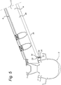
- FIG. 5 a detail is shown of a greenhouse in which under the glass panels 6 a film layer 32 is tensioned. Between this film layer 32 and the glass panels, a cavity 33 is thus formed that creates an insulating effect.
- the fastening of the film to the gutter 3 is shown; the opposite side of the film 32 is fastened in the same way (not shown) to the ridge of the greenhouse.
- the film flap 34 protrudes outwards, so that only parts of the strip 21 are in contact with the internal walls of the undercut chamber 20 which, in this example, forms an integral part of the gutter 3.
- a separate section (not shown) can be fastened with such an undercut chamber to the gutter.
Landscapes
- Engineering & Computer Science (AREA)
- Architecture (AREA)
- Civil Engineering (AREA)
- Structural Engineering (AREA)
- Life Sciences & Earth Sciences (AREA)
- Environmental Sciences (AREA)
- Greenhouses (AREA)
Claims (21)
- Befestigungssystem, das ein flexibles Bahnelement (7, 32) sowie wenigstens einen flachen Streifen (21), der an dem Bahnelement angebracht ist, mit Hauptflächen (30, 31), die voneinander weg gewandt sind und parallel zueinander sind, sowie wenigstens einen Befestigungs-Teilabschnitt (8, 18) umfasst, der eine hinterschnittene Kammer (20) sowie eine Längsöffnung (23) aufweist, die sich in diese Kammer hinein öffnet, wobei der Streifen in der Kammer des Befestigungs-Teilabschnitts so aufgenommen ist, dass eine der Hauptflächen (30) desselben der Längsöffnung zugewandt ist und die andere Hauptfläche (31) von der Längsöffnung weg gewandt ist, so dass sich das an dem Streifen (21) befestigte Bahnelement von dem Befestigungs-Teilabschnitt über die Längsöffnung desselben nach außen erstreckt,
wobei das Bahnelement (7, 32) an der Hauptfläche (30) des Streifens (21), die der Längsöffnung zugewandt ist, an einer Befestigungsposition befestigt ist, die sich auf der Höhe der Längsöffnung (23) befindet, und wenigstens die andere Hauptfläche (31) des Streifens frei lässt, und der Streifen (21) in einem Abstand zu einer freien Kante des Bahnelementes (7, 32) angeordnet ist, so dass eine freie Lasche (19, 34) entsteht, die zwischen diesem Streifen (21) und dieser freien Kante des Bahnelementes (7, 32) ausgebildet ist, und sich die Lasche (19, 34) von der Befestigungsposition an dem Streifen (21) in die Längsöffnung (23) hinein erstreckt. - Befestigungssystem nach Anspruch 1, wobei sich die Lasche (19, 34) durch die Längsöffnung (23) des Befestigungs-Teilabschnitts (8, 18) davon nach außen erstreckt.
- Befestigungssystem nach einem der Ansprüche 1 oder 2, wobei die Fläche (30) des Streifens (21), die der Längsöffnung (23) zugewandt ist, an der Innenfläche der Kammer (20) an einander gegenüberliegenden Seiten der Längsöffnung (23) derselben anliegt oder direkt zum Anliegen daran gebracht werden kann.
- Befestigungssystem nach einem der Ansprüche 1-3, wobei der flache Streifen (21) eine Gesamt-Dickenabmessung hat, die wenigstens eine Größenordnung kleiner ist als die Breite derselben.
- Befestigungssystem nach einem der Ansprüche 1-4, wobei das flexible Element (7, 32) mittels einer Befestigung (24) an dem Streifen (21) befestigt ist, die mit Vernähen, Verkleben, Verschmelzen, Vernieten oder dergleichen hergestellt wird.
- Befestigungssystem nach Anspruch 5, wobei sich die Befestigung (24), in der Breitenrichtung des Streifens gesehen, im Wesentlichen in der Mitte des Streifens erstreckt.
- Befestigungssystem nach Anspruch 5 oder 6, wobei die Befestigung (24) zwischen des flexiblen Elementes (7, 32) an dem Streifen (21) an den Hauptflächen des flexiblen Elementes und des Streifens angeordnet ist, die einander zugewandt sind.
- Befestigungssystem nach einem der Ansprüche 1-7, wobei der Befestigungs-Teil-abschnitt (8, 18) eine hinterschnittene Kammer (20) mit einem im Wesentlichen rechteckigen oder quadratischen Innen-Querschnitt aufweist.
- Befestigungssystem nach einem der Ansprüche 1-8, wobei die Längsöffnung (23) im Wesentlichen in der Mitte einer der Wände angeordnet ist, die die Kammer begrenzen.
- Befestigungssystem nach einem der Ansprüche 1-9, wobei die Breitenrichtung des Streifens (21) quer, vorzugsweise um ungefähr 90°, in Bezug auf das flexible Element (7, 32) ausgerichtet ist.
- Befestigungssystem nach einem der Ansprüche 1-10, wobei die Querschnitts-Abmessungen des Streifens (21) und die Querschnitts-Abmessungen der hinterschnittenen Kammer (20) so ausgewählt werden, dass der Streifen in der Kammer arretiert wird, um zu verhindern, dass der Streifen aus der Kammer über die Längsöffnung (23) derselben austritt.
- Befestigungssystem nach Anspruch 11, wobei die hinterschnittene Kammer (20) jedes Befestigungs-Teilabschnitts (8, 18) an wenigstens einem Längsende (25) derselben offen ist, um einen Streifen (21) in die Kammer hinein zu schieben, wobei das flexible Element (7, 32) und die Lasche (19, 34) an dem Streifen angebracht sind.
- Gewächshaus oder Lagerhaus, das ein Dach, eine tragende Struktur, von der das Dach getragen wird, sowie eine Abschirmungs-Installation umfasst, die ein flexibles Bahnelement (7) umfasst, das als eine im Wesentlichen horizontal ausgerichtete Abschirmung ausgeführt ist, die an einander gegenüberliegenden Kanten derselben an der tragenden Struktur in jedem Fall mittels eines Befestigungssystems nach einem der vorangehenden Ansprüche aufgehängt ist.
- Gewächshaus nach Anspruch 13, wobei die tragende Struktur mit zueinander parallelen Trägern versehen ist, zwischen denen ein im wesentlichen horizontaler Drahteinsatz (17) mit zueinander parallelen Drähten verspannt ist, und die Befestigungs-Teilabschnitte quer, vorzugsweise senkrecht, in Bezug auf die Drähte des Drahteinsatzes ausgerichtet sind, die Abschirmung und wenigstens einer der Befestigungs-Teilabschnitte (8), der als ein Abschirmungs-Teilabschnitt ausgeführt ist, von dem Drahteinsatz so getragen werden, dass sie hin und her verschoben werden können, sowie mit einer Antriebseinrichtung versehen ist, mit der der wenigstens eine Abschirmungs-Teilabschnitt und die Abschirmung hin und her verschoben werden.
- Gewächshaus oder Lagerhaus, das eine tragende Struktur sowie ein von ihr getragenes Dach umfasst, das ein flexibles Bahnelement umfasst, das an einander gegenüberliegenden Kanten desselben an der tragenden Struktur in jedem Fall mittels eines Befestigungssystems nach einem der Ansprüche 1-12 befestigt ist.
- Gewächshaus nach Anspruch 15, wobei das Dach Rinnen (3) und einen First umfasst, der mit Stäben (4) zwischen den Rinnen (3) in einer größeren Höhe getragen wird als die Rinnen, wobei Platten (6) zwischen dem First, der entsprechenden Rinne (3) und den Stangen (4) aufgenommen sind, die sich von der Rinne zu dem First erstrecken und so einen Dach-Teil bilden, und sich das flexible Bahnelement (32) in einem Abstand zu dem Dach-Teil und dem Wesentlichen parallel dazu erstreckt und so ein Hohlraum (33) zwischen dem Dach-Teil und dem flexiblen Bahnelement (32) gebildet wird, wobei das flexible Bahnelement (32) in jedem Fall an oder nahe an der Rinne (3) und dem First mittels eines entsprechenden Befestigungssystems befestigt ist.
- Anordnung (22) zum Einsatz in dem Gewächshaus nach einem der Ansprüche 13-16, die ein flexibles Bahnelement (7, 32) sowie wenigstens einen flachen Streifen (21) umfasst, der an dem flexiblen Bahnelement befestigt ist, und der eine erste sowie eine zweite Hauptfläche (30, 31) aufweist, die voneinander weg gewandt und parallel zueinander sind, wobei sich der Streifen in der Längsrichtung des flexiblen Bahnelementes erstreckt, das flexible Bahnelement an der ersten Hauptfläche (30) des Streifens mittels einer geradlinigen Befestigung (24) befestigt ist, die beispielsweise mit Vernähen, Verkleben, Verschmelzen, Vernieten oder dergleichen hergestellt wird und sich, in der Breitenrichtung des Streifens gesehen, im Wesentlichen in der Mitte des Streifens erstreckt, und die zweite Hauptfläche (31) des Streifens freigehalten wird, und der Streifen (21) in einem Abstand zu einer freien Kante des Bahnelementes (7, 32) angeordnet ist und eine freie Lasche (19, 34) bildet, die zwischen dem Streifen (21) und der freien Kante des Bahnelementes (7, 32) ausgebildet ist.
- Rolle (11), die eine Anordnung nach Anspruch 17 umfasst, die um eine Mittellinie der Rolle herum aufgerollt ist, die quer in Bezug auf die Längsrichtung der Abschirmung (7) verläuft.
- Verfahren zum Montieren eines Befestigungssystems nach einem der Ansprüche 1-12, das die folgenden Schritte umfasst:Schaffen einer Anordnung (22), die ein flexibles Bahnelement (7) sowie wenigstens einen flachen Streifen (21) umfasst, der an dem flexiblen Bahnelement befestigt ist, wobei der Streifen in einem Abstand zu der angrenzenden freien Kante des flexiblen Bahnelementes befestigt ist und eine freie Lasche (19) bildet,Bereitstellen eines Befestigungs-Teilabschnitts (8, 18), der eine hinterschnittene Kammer (20) und eine Längsöffnung (23) aufweist, die sich in diese Kammer hinein öffnet,Einführen der Anordnung (22) in das freie Längsende (25) des Befestigungs-Teilabschnitts (8, 18), so dass ein Ende des Streifens (21) und das daran befestigte flexible Bahnelement (7) und die daran befestigte Lasche (19) in ein Längsende (25) des Befestigungs-Teilabschnitts hineinreichen und die Abschirmung über die Längsöffnung (23) nach außen vorsteht,Bewegen der so in den Befestigungs-Teilabschnitt (8, 18) eingeführten Anordnung (22) an dem Befestigungs-Teilabschnitt entlang.
- Verfahren nach Anspruch 19, das die folgenden Schritte umfasst:Bereitstellen einer Anordnung (22) in Form einer Rolle (11), wobei die Mittellinie der Rolle quer zu der Längsrichtung des Streifens (21) ausgerichtet ist,Anordnen der Rolle nahe an einem freien Längsende (25) des Befestigungs-Teilabschnitts (8, 18),Abrollen der Anordnung (22) der Rolle (11) und Verschieben des abgerollten Endes der Anordnung zu dem freien oder offenen Längsende des Befestigungs-Teilabschnitts.
- Verfahren nach Anspruch 20, das die folgenden Schritte umfasst:nach Abrollen der Anordnung (22) Ausrichten der Breitenrichtung des Streifens (21) quer in Bezug auf die Abschirmung,Falten oder Umbiegen der Lasche (19) in Bezug auf das flexible Bahnelement (7)anschließend Einführen des Streifens (21) in den Befestigungs-Teilabschnitt (8, 18).
Applications Claiming Priority (2)
| Application Number | Priority Date | Filing Date | Title |
|---|---|---|---|
| NL2012719A NL2012719B1 (nl) | 2014-04-30 | 2014-04-30 | Bevestigingssysteem en scherminstallatie voor een kas, alsmede werkwijze voor het aanbrengen daarvan. |
| PCT/NL2015/050291 WO2015167334A1 (en) | 2014-04-30 | 2015-04-30 | Fastening system and screen installation for a greenhouse, as well as method for attaching the same |
Publications (2)
| Publication Number | Publication Date |
|---|---|
| EP3136839A1 EP3136839A1 (de) | 2017-03-08 |
| EP3136839B1 true EP3136839B1 (de) | 2018-08-15 |
Family
ID=50896433
Family Applications (1)
| Application Number | Title | Priority Date | Filing Date |
|---|---|---|---|
| EP15728198.1A Active EP3136839B1 (de) | 2014-04-30 | 2015-04-30 | Abschirmungsvorrichtung für ein gewächshaus und installierungsverfahren |
Country Status (6)
| Country | Link |
|---|---|
| US (1) | US10617067B2 (de) |
| EP (1) | EP3136839B1 (de) |
| CA (1) | CA2947400C (de) |
| ES (1) | ES2692996T3 (de) |
| NL (1) | NL2012719B1 (de) |
| WO (1) | WO2015167334A1 (de) |
Families Citing this family (9)
| Publication number | Priority date | Publication date | Assignee | Title |
|---|---|---|---|---|
| US10004180B1 (en) * | 2015-12-10 | 2018-06-26 | Gro-Tech Systems, Inc. | Modular enclosure with automated curtain deployment |
| US11185017B2 (en) * | 2018-07-03 | 2021-11-30 | Palram Applications (1995) Ltd. | System and method for controlling light in a facility |
| NL2023273B1 (nl) * | 2019-06-07 | 2020-12-22 | Van Der Ende Pompen B V | Kas voorzien van ventilatiesysteem |
| IL288844B2 (en) * | 2019-06-19 | 2024-05-01 | Top Greenhouses Ltd | Cover unfolds and retracts |
| NL2026839B1 (nl) * | 2020-11-05 | 2022-06-27 | Alweco Scherminstallaties Bv | Spantbeugel voor een kas en combinaties daarvan met een klem, een doekgeleider en een geleidedraadklem |
| KR102623822B1 (ko) * | 2021-04-09 | 2024-01-11 | 농업회사법인 도시농업유한회사 | 전천후 버블 온실 |
| US20230138490A1 (en) * | 2021-10-29 | 2023-05-04 | Beth Ann Wexell | Roof Sunshade Device |
| KR102709249B1 (ko) * | 2023-10-11 | 2024-09-25 | 대경에이티 주식회사 | 온실하우스용 수평커튼 장치 |
| NL2036274B1 (en) * | 2023-11-15 | 2025-05-27 | Van Der Valk Systemen B V | Device for coupling drive means to a screen profile in a screen assembly |
Family Cites Families (13)
| Publication number | Priority date | Publication date | Assignee | Title |
|---|---|---|---|---|
| US3116097A (en) * | 1961-05-16 | 1963-12-31 | William H Novales | Curtain assembly |
| NL8105447A (nl) * | 1981-12-02 | 1983-07-01 | Priva Handel Bv | Isolatiescherm. |
| US4697326A (en) * | 1985-05-28 | 1987-10-06 | Faircloth F Craige | Screen means |
| GB2251777B (en) * | 1991-01-17 | 1994-07-27 | Brian Edward Stephens | Crop cover arrangement |
| NL1011546C2 (nl) * | 1999-03-12 | 2000-09-14 | Holland Scherming B V | Doekconstructie. |
| DE102005024657C5 (de) * | 2004-11-19 | 2016-04-21 | Webasto Ag | Rolloanordnung für ein Fahrzeug |
| DE102005040758B4 (de) * | 2005-08-26 | 2010-09-23 | Webasto Ag | Rolloanordnung |
| NL1034598C2 (nl) * | 2007-10-30 | 2009-05-06 | Peter Dekker Installaties B V | Warenhuis, scherminrichting en scherm. |
| NL2002319C2 (nl) * | 2008-12-12 | 2010-06-15 | Valk Systemen Bvvd | Werkwijze voor het installeren van een scherminrichting in een kas of warenhuis. |
| NL2002621C2 (nl) * | 2009-03-13 | 2010-09-14 | Valk Systemen Bvvd | Werkwijze voor het vervaardigen van een scherminstallatie alsmede profielen daarvoor. |
| DE102010018259B4 (de) * | 2010-04-26 | 2011-12-01 | Webasto Ag | Fahrzeugrolloanordnung, Baugruppe mit einer Fahrzeugrolloanordnung, und Dachanordnung |
| TW201331062A (zh) * | 2012-01-19 | 2013-08-01 | Macauto Ind Co Ltd | 捲簧式天窗遮陽簾 |
| EP3064386B1 (de) * | 2015-03-04 | 2020-02-12 | Inalfa Roof Systems Group B.V. | Sonnenschirmanordnung und damit ausgestattete offene Dachkonstruktion |
-
2014
- 2014-04-30 NL NL2012719A patent/NL2012719B1/nl not_active IP Right Cessation
-
2015
- 2015-04-30 ES ES15728198.1T patent/ES2692996T3/es active Active
- 2015-04-30 US US15/307,836 patent/US10617067B2/en active Active
- 2015-04-30 CA CA2947400A patent/CA2947400C/en active Active
- 2015-04-30 WO PCT/NL2015/050291 patent/WO2015167334A1/en not_active Ceased
- 2015-04-30 EP EP15728198.1A patent/EP3136839B1/de active Active
Non-Patent Citations (1)
| Title |
|---|
| None * |
Also Published As
| Publication number | Publication date |
|---|---|
| NL2012719A (nl) | 2016-02-15 |
| US20170086392A1 (en) | 2017-03-30 |
| US10617067B2 (en) | 2020-04-14 |
| ES2692996T3 (es) | 2018-12-07 |
| WO2015167334A1 (en) | 2015-11-05 |
| NL2012719B1 (nl) | 2016-07-18 |
| CA2947400A1 (en) | 2015-11-05 |
| EP3136839A1 (de) | 2017-03-08 |
| CA2947400C (en) | 2022-08-16 |
Similar Documents
| Publication | Publication Date | Title |
|---|---|---|
| US10617067B2 (en) | Fastening system and screen installation for a greenhouse, as well as method for attaching the same | |
| US8919415B1 (en) | Curtain closure system having impact resistant tension bar | |
| EP3460164A1 (de) | Isolierte türplatten | |
| DE2819194C2 (de) | Anschluß eines Nebenkanals an einen aus Blechstreifen zusammengefügten Haupt- bzw. Sammelkanal | |
| US9194128B1 (en) | Exterior mounted solar shade screen for skylights | |
| WO2011082372A1 (en) | Insulating shade for covering an architectural opening | |
| CN105339578A (zh) | 卷门 | |
| US20170096854A1 (en) | Retractable shade system and related method of manufacturing | |
| US2988183A (en) | Mullion arrangement | |
| US20080185107A1 (en) | Brace for awning roller tube | |
| EP1611303B1 (de) | Membran-wandelement für die errichtung einer zelt-oder hallenkonstruktion | |
| DE202014010819U1 (de) | Tor, insbesondere Hubtor, zum Verschließen einer Öffnung in einer zwei verschiedene Temperaturzonen voneinander trennenden Wandung | |
| DE102007001438A1 (de) | Bewegliche Isolation von Gewächshäusern durch aufblasbaren Folienmantel oder aufrollbare Isolationsmatten mit Innenraum | |
| EP2136030A2 (de) | Mobile Sonnenblende | |
| US20140069052A1 (en) | Sun Louvre Formed by a Structure Supporting an Interweave of Metal Sheets | |
| EP1774847A1 (de) | Abschirmvorrichtung und Abschirmrahmen für ein Gewächshaus, Gewächshaus und Verfahren für die Anfertigung eines solchen Gewächshaus | |
| CN223979212U (zh) | 一种农业大棚的保护装置及农业大棚 | |
| JP7554412B2 (ja) | ハウス内環境の保全シート用ハウスバンドの位置決め固定具 | |
| EP4461901A1 (de) | Tropfstreifen | |
| DE102017002757A1 (de) | Sanierungsverfahren für ein Scheddachsystem ohne Unterbrechung der Gebäudenutzung | |
| DE2019666A1 (de) | Wandelement mit Isolierung | |
| NL8100442A (nl) | Zon- en warmtescherm voor een plantenkas. | |
| CN110344547A (zh) | 一种高防水屋面系统 | |
| JPS62236978A (ja) | 簡易建物 | |
| NL2006055A (nl) | Schermsysteem voor een warenhuis. |
Legal Events
| Date | Code | Title | Description |
|---|---|---|---|
| STAA | Information on the status of an ep patent application or granted ep patent |
Free format text: STATUS: THE INTERNATIONAL PUBLICATION HAS BEEN MADE |
|
| PUAI | Public reference made under article 153(3) epc to a published international application that has entered the european phase |
Free format text: ORIGINAL CODE: 0009012 |
|
| STAA | Information on the status of an ep patent application or granted ep patent |
Free format text: STATUS: REQUEST FOR EXAMINATION WAS MADE |
|
| 17P | Request for examination filed |
Effective date: 20161027 |
|
| AK | Designated contracting states |
Kind code of ref document: A1 Designated state(s): AL AT BE BG CH CY CZ DE DK EE ES FI FR GB GR HR HU IE IS IT LI LT LU LV MC MK MT NL NO PL PT RO RS SE SI SK SM TR |
|
| AX | Request for extension of the european patent |
Extension state: BA ME |
|
| DAV | Request for validation of the european patent (deleted) | ||
| DAX | Request for extension of the european patent (deleted) | ||
| RIC1 | Information provided on ipc code assigned before grant |
Ipc: A01G 9/22 20060101ALI20171222BHEP Ipc: E04D 11/00 20060101ALI20171222BHEP Ipc: E04D 13/00 20060101ALI20171222BHEP Ipc: E04D 13/064 20060101ALI20171222BHEP Ipc: A01G 9/24 20060101ALI20171222BHEP Ipc: E04H 5/08 20060101ALI20171222BHEP Ipc: E04H 5/02 20060101ALI20171222BHEP Ipc: A01G 9/14 20060101AFI20171222BHEP |
|
| GRAP | Despatch of communication of intention to grant a patent |
Free format text: ORIGINAL CODE: EPIDOSNIGR1 |
|
| STAA | Information on the status of an ep patent application or granted ep patent |
Free format text: STATUS: GRANT OF PATENT IS INTENDED |
|
| RIC1 | Information provided on ipc code assigned before grant |
Ipc: A01G 9/22 20060101AFI20180201BHEP |
|
| INTG | Intention to grant announced |
Effective date: 20180227 |
|
| RIN1 | Information on inventor provided before grant (corrected) |
Inventor name: BROOS, JOHAN MARTIEN Inventor name: VAN DEURSEN, ADRIANUS GERARDUS Inventor name: PRINS, VINCENT |
|
| GRAS | Grant fee paid |
Free format text: ORIGINAL CODE: EPIDOSNIGR3 |
|
| GRAA | (expected) grant |
Free format text: ORIGINAL CODE: 0009210 |
|
| STAA | Information on the status of an ep patent application or granted ep patent |
Free format text: STATUS: THE PATENT HAS BEEN GRANTED |
|
| AK | Designated contracting states |
Kind code of ref document: B1 Designated state(s): AL AT BE BG CH CY CZ DE DK EE ES FI FR GB GR HR HU IE IS IT LI LT LU LV MC MK MT NL NO PL PT RO RS SE SI SK SM TR |
|
| REG | Reference to a national code |
Ref country code: CH Ref legal event code: EP Ref country code: GB Ref legal event code: FG4D Ref country code: AT Ref legal event code: REF Ref document number: 1028652 Country of ref document: AT Kind code of ref document: T Effective date: 20180815 |
|
| REG | Reference to a national code |
Ref country code: IE Ref legal event code: FG4D |
|
| REG | Reference to a national code |
Ref country code: DE Ref legal event code: R096 Ref document number: 602015014768 Country of ref document: DE |
|
| REG | Reference to a national code |
Ref country code: SE Ref legal event code: TRGR |
|
| REG | Reference to a national code |
Ref country code: NL Ref legal event code: FP |
|
| REG | Reference to a national code |
Ref country code: ES Ref legal event code: FG2A Ref document number: 2692996 Country of ref document: ES Kind code of ref document: T3 Effective date: 20181207 |
|
| REG | Reference to a national code |
Ref country code: LT Ref legal event code: MG4D |
|
| PG25 | Lapsed in a contracting state [announced via postgrant information from national office to epo] |
Ref country code: BG Free format text: LAPSE BECAUSE OF FAILURE TO SUBMIT A TRANSLATION OF THE DESCRIPTION OR TO PAY THE FEE WITHIN THE PRESCRIBED TIME-LIMIT Effective date: 20181115 Ref country code: LT Free format text: LAPSE BECAUSE OF FAILURE TO SUBMIT A TRANSLATION OF THE DESCRIPTION OR TO PAY THE FEE WITHIN THE PRESCRIBED TIME-LIMIT Effective date: 20180815 Ref country code: FI Free format text: LAPSE BECAUSE OF FAILURE TO SUBMIT A TRANSLATION OF THE DESCRIPTION OR TO PAY THE FEE WITHIN THE PRESCRIBED TIME-LIMIT Effective date: 20180815 Ref country code: IS Free format text: LAPSE BECAUSE OF FAILURE TO SUBMIT A TRANSLATION OF THE DESCRIPTION OR TO PAY THE FEE WITHIN THE PRESCRIBED TIME-LIMIT Effective date: 20181215 Ref country code: RS Free format text: LAPSE BECAUSE OF FAILURE TO SUBMIT A TRANSLATION OF THE DESCRIPTION OR TO PAY THE FEE WITHIN THE PRESCRIBED TIME-LIMIT Effective date: 20180815 Ref country code: GR Free format text: LAPSE BECAUSE OF FAILURE TO SUBMIT A TRANSLATION OF THE DESCRIPTION OR TO PAY THE FEE WITHIN THE PRESCRIBED TIME-LIMIT Effective date: 20181116 Ref country code: NO Free format text: LAPSE BECAUSE OF FAILURE TO SUBMIT A TRANSLATION OF THE DESCRIPTION OR TO PAY THE FEE WITHIN THE PRESCRIBED TIME-LIMIT Effective date: 20181115 |
|
| PG25 | Lapsed in a contracting state [announced via postgrant information from national office to epo] |
Ref country code: HR Free format text: LAPSE BECAUSE OF FAILURE TO SUBMIT A TRANSLATION OF THE DESCRIPTION OR TO PAY THE FEE WITHIN THE PRESCRIBED TIME-LIMIT Effective date: 20180815 Ref country code: LV Free format text: LAPSE BECAUSE OF FAILURE TO SUBMIT A TRANSLATION OF THE DESCRIPTION OR TO PAY THE FEE WITHIN THE PRESCRIBED TIME-LIMIT Effective date: 20180815 Ref country code: AL Free format text: LAPSE BECAUSE OF FAILURE TO SUBMIT A TRANSLATION OF THE DESCRIPTION OR TO PAY THE FEE WITHIN THE PRESCRIBED TIME-LIMIT Effective date: 20180815 |
|
| PG25 | Lapsed in a contracting state [announced via postgrant information from national office to epo] |
Ref country code: EE Free format text: LAPSE BECAUSE OF FAILURE TO SUBMIT A TRANSLATION OF THE DESCRIPTION OR TO PAY THE FEE WITHIN THE PRESCRIBED TIME-LIMIT Effective date: 20180815 Ref country code: CZ Free format text: LAPSE BECAUSE OF FAILURE TO SUBMIT A TRANSLATION OF THE DESCRIPTION OR TO PAY THE FEE WITHIN THE PRESCRIBED TIME-LIMIT Effective date: 20180815 Ref country code: RO Free format text: LAPSE BECAUSE OF FAILURE TO SUBMIT A TRANSLATION OF THE DESCRIPTION OR TO PAY THE FEE WITHIN THE PRESCRIBED TIME-LIMIT Effective date: 20180815 Ref country code: PL Free format text: LAPSE BECAUSE OF FAILURE TO SUBMIT A TRANSLATION OF THE DESCRIPTION OR TO PAY THE FEE WITHIN THE PRESCRIBED TIME-LIMIT Effective date: 20180815 |
|
| REG | Reference to a national code |
Ref country code: DE Ref legal event code: R097 Ref document number: 602015014768 Country of ref document: DE |
|
| PG25 | Lapsed in a contracting state [announced via postgrant information from national office to epo] |
Ref country code: SK Free format text: LAPSE BECAUSE OF FAILURE TO SUBMIT A TRANSLATION OF THE DESCRIPTION OR TO PAY THE FEE WITHIN THE PRESCRIBED TIME-LIMIT Effective date: 20180815 Ref country code: SM Free format text: LAPSE BECAUSE OF FAILURE TO SUBMIT A TRANSLATION OF THE DESCRIPTION OR TO PAY THE FEE WITHIN THE PRESCRIBED TIME-LIMIT Effective date: 20180815 Ref country code: DK Free format text: LAPSE BECAUSE OF FAILURE TO SUBMIT A TRANSLATION OF THE DESCRIPTION OR TO PAY THE FEE WITHIN THE PRESCRIBED TIME-LIMIT Effective date: 20180815 |
|
| PLBE | No opposition filed within time limit |
Free format text: ORIGINAL CODE: 0009261 |
|
| STAA | Information on the status of an ep patent application or granted ep patent |
Free format text: STATUS: NO OPPOSITION FILED WITHIN TIME LIMIT |
|
| 26N | No opposition filed |
Effective date: 20190516 |
|
| PG25 | Lapsed in a contracting state [announced via postgrant information from national office to epo] |
Ref country code: SI Free format text: LAPSE BECAUSE OF FAILURE TO SUBMIT A TRANSLATION OF THE DESCRIPTION OR TO PAY THE FEE WITHIN THE PRESCRIBED TIME-LIMIT Effective date: 20180815 |
|
| REG | Reference to a national code |
Ref country code: AT Ref legal event code: UEP Ref document number: 1028652 Country of ref document: AT Kind code of ref document: T Effective date: 20180815 |
|
| PG25 | Lapsed in a contracting state [announced via postgrant information from national office to epo] |
Ref country code: MC Free format text: LAPSE BECAUSE OF FAILURE TO SUBMIT A TRANSLATION OF THE DESCRIPTION OR TO PAY THE FEE WITHIN THE PRESCRIBED TIME-LIMIT Effective date: 20180815 Ref country code: LU Free format text: LAPSE BECAUSE OF NON-PAYMENT OF DUE FEES Effective date: 20190430 |
|
| PG25 | Lapsed in a contracting state [announced via postgrant information from national office to epo] |
Ref country code: TR Free format text: LAPSE BECAUSE OF FAILURE TO SUBMIT A TRANSLATION OF THE DESCRIPTION OR TO PAY THE FEE WITHIN THE PRESCRIBED TIME-LIMIT Effective date: 20180815 |
|
| PG25 | Lapsed in a contracting state [announced via postgrant information from national office to epo] |
Ref country code: IE Free format text: LAPSE BECAUSE OF NON-PAYMENT OF DUE FEES Effective date: 20190430 |
|
| PG25 | Lapsed in a contracting state [announced via postgrant information from national office to epo] |
Ref country code: PT Free format text: LAPSE BECAUSE OF FAILURE TO SUBMIT A TRANSLATION OF THE DESCRIPTION OR TO PAY THE FEE WITHIN THE PRESCRIBED TIME-LIMIT Effective date: 20181215 |
|
| PG25 | Lapsed in a contracting state [announced via postgrant information from national office to epo] |
Ref country code: CY Free format text: LAPSE BECAUSE OF FAILURE TO SUBMIT A TRANSLATION OF THE DESCRIPTION OR TO PAY THE FEE WITHIN THE PRESCRIBED TIME-LIMIT Effective date: 20180815 |
|
| PG25 | Lapsed in a contracting state [announced via postgrant information from national office to epo] |
Ref country code: MT Free format text: LAPSE BECAUSE OF FAILURE TO SUBMIT A TRANSLATION OF THE DESCRIPTION OR TO PAY THE FEE WITHIN THE PRESCRIBED TIME-LIMIT Effective date: 20180815 Ref country code: HU Free format text: LAPSE BECAUSE OF FAILURE TO SUBMIT A TRANSLATION OF THE DESCRIPTION OR TO PAY THE FEE WITHIN THE PRESCRIBED TIME-LIMIT; INVALID AB INITIO Effective date: 20150430 |
|
| PG25 | Lapsed in a contracting state [announced via postgrant information from national office to epo] |
Ref country code: MK Free format text: LAPSE BECAUSE OF FAILURE TO SUBMIT A TRANSLATION OF THE DESCRIPTION OR TO PAY THE FEE WITHIN THE PRESCRIBED TIME-LIMIT Effective date: 20180815 |
|
| P01 | Opt-out of the competence of the unified patent court (upc) registered |
Effective date: 20230518 |
|
| PGFP | Annual fee paid to national office [announced via postgrant information from national office to epo] |
Ref country code: SE Payment date: 20250228 Year of fee payment: 11 |
|
| PGFP | Annual fee paid to national office [announced via postgrant information from national office to epo] |
Ref country code: NL Payment date: 20250407 Year of fee payment: 11 |
|
| PGFP | Annual fee paid to national office [announced via postgrant information from national office to epo] |
Ref country code: DE Payment date: 20250428 Year of fee payment: 11 |
|
| PGFP | Annual fee paid to national office [announced via postgrant information from national office to epo] |
Ref country code: ES Payment date: 20250513 Year of fee payment: 11 |
|
| PGFP | Annual fee paid to national office [announced via postgrant information from national office to epo] |
Ref country code: BE Payment date: 20250424 Year of fee payment: 11 Ref country code: IT Payment date: 20250422 Year of fee payment: 11 |
|
| PGFP | Annual fee paid to national office [announced via postgrant information from national office to epo] |
Ref country code: FR Payment date: 20250424 Year of fee payment: 11 |
|
| PGFP | Annual fee paid to national office [announced via postgrant information from national office to epo] |
Ref country code: CH Payment date: 20250501 Year of fee payment: 11 |
|
| PGFP | Annual fee paid to national office [announced via postgrant information from national office to epo] |
Ref country code: AT Payment date: 20250417 Year of fee payment: 11 |
|
| PGFP | Annual fee paid to national office [announced via postgrant information from national office to epo] |
Ref country code: GB Payment date: 20260304 Year of fee payment: 12 |
|
| REG | Reference to a national code |
Ref country code: CH Ref legal event code: U11 Free format text: ST27 STATUS EVENT CODE: U-0-0-U10-U11 (AS PROVIDED BY THE NATIONAL OFFICE) Effective date: 20260501 |