EP4461901A1 - Tropfstreifen - Google Patents
Tropfstreifen Download PDFInfo
- Publication number
- EP4461901A1 EP4461901A1 EP24175250.0A EP24175250A EP4461901A1 EP 4461901 A1 EP4461901 A1 EP 4461901A1 EP 24175250 A EP24175250 A EP 24175250A EP 4461901 A1 EP4461901 A1 EP 4461901A1
- Authority
- EP
- European Patent Office
- Prior art keywords
- wall
- drip strip
- drip
- strip
- length
- Prior art date
- Legal status (The legal status is an assumption and is not a legal conclusion. Google has not performed a legal analysis and makes no representation as to the accuracy of the status listed.)
- Pending
Links
Images





Classifications
-
- E—FIXED CONSTRUCTIONS
- E04—BUILDING
- E04F—FINISHING WORK ON BUILDINGS, e.g. STAIRS, FLOORS
- E04F13/00—Coverings or linings, e.g. for walls or ceilings
- E04F13/02—Coverings or linings, e.g. for walls or ceilings of plastic materials hardening after applying, e.g. plaster
- E04F13/04—Bases for plaster
- E04F13/06—Edge-protecting borders
-
- E—FIXED CONSTRUCTIONS
- E04—BUILDING
- E04F—FINISHING WORK ON BUILDINGS, e.g. STAIRS, FLOORS
- E04F13/00—Coverings or linings, e.g. for walls or ceilings
- E04F13/02—Coverings or linings, e.g. for walls or ceilings of plastic materials hardening after applying, e.g. plaster
- E04F13/04—Bases for plaster
- E04F13/06—Edge-protecting borders
- E04F13/068—Edge-protecting borders combined with mesh material or the like to allow plaster to bond therewith
-
- E—FIXED CONSTRUCTIONS
- E04—BUILDING
- E04F—FINISHING WORK ON BUILDINGS, e.g. STAIRS, FLOORS
- E04F19/00—Other details of constructional parts for finishing work on buildings
- E04F19/02—Borders; Finishing strips, e.g. beadings; Light coves
-
- E—FIXED CONSTRUCTIONS
- E04—BUILDING
- E04F—FINISHING WORK ON BUILDINGS, e.g. STAIRS, FLOORS
- E04F13/00—Coverings or linings, e.g. for walls or ceilings
- E04F13/02—Coverings or linings, e.g. for walls or ceilings of plastic materials hardening after applying, e.g. plaster
- E04F13/04—Bases for plaster
- E04F13/06—Edge-protecting borders
- E04F2013/065—Edge-protecting borders for lower edges of outer insulation layers
-
- E—FIXED CONSTRUCTIONS
- E04—BUILDING
- E04F—FINISHING WORK ON BUILDINGS, e.g. STAIRS, FLOORS
- E04F13/00—Coverings or linings, e.g. for walls or ceilings
- E04F13/02—Coverings or linings, e.g. for walls or ceilings of plastic materials hardening after applying, e.g. plaster
- E04F13/04—Bases for plaster
- E04F13/06—Edge-protecting borders
- E04F2013/066—Edge-protecting borders for expansion joints between two plaster layers
Definitions
- This invention concerns a drip strip, in particular a rollable drip strip to be installed in building insulation systems.
- drip strips A lot of drip strips are known. There are drip strips having an angled cross section, wherein there is a foot located close to the joint between the arms of the angle. Usually, drip strips comprise a wall that is generally vertical after installation of the strip and extends the face of the façade.
- drip strips are made as angle bars. Since drip strips have the form of angle bars, they are stored and offered for sale in the so-called long-load packages, also referred to in short as long loads.
- Long loads are packages that are relatively short in height, moderately wide and relatively long. For packages with drip strips, the long loads are around 0.1 metre in height, 0.3 in width and around 3 metres in length. Given the nature of the long loads, such packages require special treatment during transportation and storage.
- the purpose of the present invention is to provide a drip strip that can be rolled up or wound on a roller for transporting or storing the drip strip.
- the drip strip according to the present invention is characterised in that it comprises a first wall that extends along the length of the drip strip, a second wall that extends along the length of the drip strip, wherein the second wall is connected to the first wall by means of a swivel joint, a third wall that extends along the length of the drip strip, wherein the third wall is connected to the first wall by means of a swivel joint, opposite to the second wall, wherein the first wall, second wall and third wall have the form of a flexible flat bar.
- the drip strip according to the invention further comprises an adhesive element arranged on one out of the first wall, second wall and third wall.
- the adhesive element is arranged on the first wall.
- the adhesive element is arranged on the second wall or third wall.
- the drip strip according to the invention further comprises at least one mounting element arranged on at least one of the second wall and third wall.
- the mounting element is selected from a group including mounting holes, goffering, grooving and corrugation.
- the mounting element is formed by multiple holes arranged along at least one of the second wall and third wall.
- the drip strip according to the invention further comprises at least one auxiliary mounting element attached to at least one of the second wall and third wall.
- the auxiliary mounting element is in a form of a band extending along the length of the drip strip.
- the auxiliary mounting element is selected from a group including a mesh, mat, woven fabric and unwoven fabric.
- the drip strip according to the invention is in a form selected from among a roll, roller and spool.
- the drip strip according to the present invention is in a form form of a flat drip strip that can be rolled up or wound on a roller.
- the rollable drip strip according to the present invention can be rolled up or wound on a roller, it occupies much less space. This makes the rolled drip strip according to the present invention easier to transport and store.
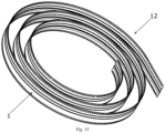
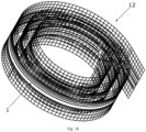
- a drip strip 1 according to the invention which can be rolled into a roll 12 or wound on a roller.
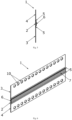
- the drip strip 1 according to the invention comprises a first wall 2 having the form of a flexible flat bar, wherein the wall 2 extends along the length of the drip strip 1, as shown in Figs. 2 , 4 , 6 and 8 .
- the drip strip 1 according to the invention comprises further a second wall 3 having the form of a flexible flat bar, wherein the second wall 3 extends along the length of the drip strip 1, as shown in Figs. 2 , 4 , 6 and 8 .
- the second wall 3 is connected to the first wall 1 along the length of the drip strip by means of a swivel joint 5, as shown in Figs.
- the drip strip 1 further comprises a third wall 4 having the form of a flexible flat bar, wherein the third wall 4 extends along the length of the drip strip 1, as shown in Fig. 2 , 4 , 6 and 8 .
- the third wall 4 is connected to the first wall 1 along the length of the drip strip by means of a swivel joint 5, as shown in Figs. 1 to 8 .
- the third wall 4 is connected to the first wall 1, opposite to the second wall 2, as shown in Figs. 1 to 8 .
- the swivel joint 5 is a connection that enables a rotational change of an orientation of one of the walls 2, 3, 4 relative to the other of the walls 2, 3, 4, respectively, what will be described below in more detail.
- the drip strip 1 comprises an adhesive element 6.
- the adhesive element 6 is arranged on one of the first wall 2, second wall 3 and third wall 4. In one of the embodiments, the adhesive element 6 is arranged on the first wall 2, as shown in Figs. 5 to 8 . In another embodiment, the adhesive element 6 is arranged on the second wall 3, as shown in Figs. 1 to 4 .
- the adhesive element is arranged on a wall 2, 3, 4 along the length of the drip strip 1.
- the adhesive element is used for adhering the wall on which it is arranged with the adjacent wall, what will be described below in more detail.
- the adhesive element 6 according to the invention is, for example, but not limited to, a layer of adhesive or a double-sided tape.
- the adhesive element 6 is covered with protective element 7, as shown in Figs. 2 , 4 , 6 and 8 , in order to protect the adhesive element 6 against deterioration of its adhesive properties, for example by contaminating the surface of the adhesive element 6, and against accidental and unintended adhering of the adhesive element 6 to another wall of the drip strip 1 or to another external object.
- the drip strip 1 further comprises at least a mounting element 10 arranged on at least one of the second wall 3 and third wall 4.
- the mounting element 10 is formed by mounting holes.
- the mounting element 10 is formed by multiple mounting holes arranged along at least one of the second wall 3 and third wall 4, arranged along the length of the drip strip 1.
- the drip strip 1 comprises a mounting element 10 in the form of two groups of mounting holes, each arranged on the second wall 3 and third wall 4, respectively, arranged along the drip strip, as shown in Figs. 2 and 6 .
- the mounting element 10 is formed by goffering, grooving or corrugation arranged on at least one of the second wall 3 and third wall 4.
- the goffering, grooving or corrugation is arranged on at least one of the second wall 3 and third wall 4 and extends along the length of the drip strip 1.
- the drip strip 1 comprises a mounting element 10 in the form of goffering, grooving or corrugation, each arranged on the second wall 3 and third wall 4, respectively, extending along the drip strip (not shown in the figures).
- the mounting element(s) 10 provided in the drip strip 1 according to the invention enhance the fastening of that strip in adhesive or coating mortars during installation of the drip strip 1 in a construction plane.
- the mounting element(s) 10 can also be formed by other commonly used solutions for anchoring a component of a construction product having the form of construction strips, including also drip strip, in construction mortars.
- the drip strip 1 preferably comprises at least one auxiliary mounting element 11 attached to at least one of the second wall 3 and third wall 4.
- the drip strip 1 comprises one auxiliary mounting element 11 attached to one out of the second wall 3 and third wall 4, which extends along the length of the drip strip 1 (not shown in the figures).
- the drip strip 1 comprises two auxiliary mounting elements 11, each attached to the second wall 3 and third wall 4, respectively, extending along the length of the drip strip 1, as shown in Figs. 4 and 8 .
- the auxiliary mounting element 11 is an element featuring a considerably higher penetrability and/or permeability of construction mortars within that auxiliary mounting element 11.
- the auxiliary mounting element 11 is formed by, for example, but not limited to, a mesh, mat, woven fabric or unwoven fabric. Any materials can be used that ensure a high penetrability and/or permeability for construction mortars.
- the auxiliary mounting element 11 is provided in the form of a band, as shown in Figs. 4 to 8 . The use of the auxiliary mounting element 11 ensures secure installation of the drip strip according to the invention in a construction plane.
- the drip strip 1 according to the invention can be produced as a single integrated element comprising a first wall 2, second wall 3 and third wall 4.
- the mounting element(s) 10 is/are made in the drip strip 1, having the form of holes, goffering, grooving or corrugation, arranged as described above.
- the mounting element(s) 10 is/are produced during the production of the drip strip 1 comprising a first wall 2, second wall 3 and third wall 4, in the form of, for example, but not limited to, goffering, grooving or corrugation.
- the adhesive element 6 is attached to the drip strip 1 on one out of the first wall 2, second wall 3 and third wall 4, respectively, to obtain a drip strip in the embodiments as specified above.
- at least one auxiliary mounting element 11 is attached to the produced drip strip 1 comprising the first wall 2, second wall 3 and third wall 4 to obtain the drip strip in the preferred embodiments, as specified above.
- the drip strip 1 according to the invention is produced of a flexible material that makes it possible to roll the drip strip 1 into a roll 12 or to wind it on a roller or spool without permanently changing its shape or losing its structural integrity, in particular, but not limited to, without permanent deformation, cracking, tearing or breaking.
- the drip strip 1 according to the invention is produced, for example, but not limited to, of a flexible plastic such as PVC, polyethylene or polypropylene.
- the drip strip 1 according to the invention is produced, for example, but not limited to, by extrusion, coextrusion.
- the auxiliary mounting element 11 is produced of a flexible material such as, for example, but not limited to, PVC, glass material or rock material. Any materials and methods can be used that are appropriate for producing a rolled drip strip 1 and known to a person skilled in the art of building profiles.
- the drip strip 1 according to the invention is obtained wherein a first wall 2, second wall 3 and third wall 4, interconnected by means of corresponding swivel joints 5, are oriented relative to one another so that they are positioned generally in the same plane, as shown in Figs. 1 to 8 .
- the first wall 2 and the second wall 3, the second wall 3 and the third wall 4, and the first wall 2 and the third wall 4, are oriented relative to each other generally at 180 degrees, as shown in Figs. 1 to 8 .
- the drip strip 1 according to the invention is rolled into a roll 12, as schematically shown in simplified form in Figs. 13 to 18 .
- the drip strip 1 is wound on a roller or spool (not shown in the figures).
- a rolled drip strip 1 according to the invention is obtained.
- the rolled drip strip 1 according to the invention having the form of a roll 12, roller, spool or another rolled up form, takes much less space than a conventional drip strip.
- a rolled drip strip 1 is much easier to store, transport and use at the place of destination such as, for example, but not limited to, a construction site than a conventional drip strip in the form of cut sections of around 2.5 to around 3 metres in length.
- the drip strip 1 according to the invention can be rolled up to form a roll 12, roller or spool containing any desirable number of linear metres of the drip strip 1 according to the invention.
- a roll 12, roller or spool can contain, for example, but not limited to, 5 metres, 10 metres, 15 metres, 20 metres, etc. of the drip strip 1 according to the invention. Therefore, a greater quantity of the drip strip can be stored, transported and used individually, while maintaining the said advantages of a rolled drip strip compared to a conventional drip strip.
- the drip strip 1 is unrolled from a roll 12, roller, spool or another wound form. Then the drip strip 1 is cut off from the roll 12, roller, spool or another wound form to the desired length.
- the cut off section of the drip strip 1 according to the invention is flat at that moment, as described above and shown in Figs. 1 to 8 .
- the material used to produce the drip strip 1 is flexible, it becomes flat once unrolled, as described above and shown in Figs. 1 to 8 , according to, but not limited to, the principle of material elasticity.
- Cutting off the drip strip 1 according to the invention from a roll 12, roller, spool or another rolled form to the desired length prevents the generation of waste, in particular having the form of short and mostly useless sections of the drip strip, as in the case of conventional drip strips. Furthermore, cutting off the drip strip 1 according to the invention from a roll 12, roller, spool or another rolled form to the desired length makes it possible to use the drip strip 1 as a single building component of the desired length that may exceed the typical lengths of conventional drip strips being around 2.5 metres to around 3 metres. In other words, owing to the drip strip 1 according to the invention, it is possible to make a drip in a construction plane of over 3 metres in length, without joining sections of drip strips together.
- the protective element if any, is removed from the adhesive element 6 and thus the adhesive surface of the adhesive element 6 is exposed.
- the wall 2, 3, 4 on which the adhesive element 6 is arranged is brought closer to the adjacent wall 2, 3, 4 by being bent at the swivel joint 5 that connects these adjacent walls 2, 3, 4, and then the walls are adhered together by means of the adhesive element 6.
- the walls 2, 3, 4 bonded together with the adhesive element 6 are generally parallel and aligned to each other along the swivel joint 5 along the length of the drip strip 1, as shown in Figs. 9 to 12 .
- the joined together first wall 2 and one of the second wall 3 or third wall 4 thus form a protrusion 9, as shown in Figs. 9 to 12 , for draining water from the construction surface.
- the free out of the second wall 3 and third wall 4 is bent by an angle required to form a plane for mounting the drip strip 1 according to the invention to the lower part of the construction plane, in order to form a folded drip strip 1 according to the invention, ready to be installed in the construction plane.
- the free out of the second wall 3 and third wall 4, respectively is bent at generally 90°, as shown in Figs. 9 to 12 .
- the adhesive element 6 is arranged on the first wall 2
- the first wall 2 and the third wall 4 are brought closer to each other by rotating the first wall 2 and the third wall 4 around the swivel joint 5 that connects them, and then both walls are adhered together to form the protrusion 9, as described above.
- the free second wall 3 is bent around the swivel joint 5 that connects said second wall 3 and first wall 2 to the desired position relative to the third wall 4, as described above and shown in Figs. 9 to 12 , to form the drip strip 1 according to the invention being ready for installation in a construction plane.
- the adhesive element 6 is arranged on the third wall 4, while folding, the first wall 2 and the third wall 4 are brought closer to each other by rotating the first wall 2 and the third wall 4 around the swivel joint 5 that connects them, and then both walls are adhered together to form the protrusion 9, as described above. Then the free second wall 3 is bent around the swivel joint 5 that connects said second wall 3 and first wall 2 to the desired position relative to the third wall 4, as described above and shown in Figs. 9 to 12 , to form the drip strip 1 according to the invention with a protrusion 9, being ready for installation in a construction plane.
- the folded drip strip 1 according to the invention is installed in a construction plane, in the areas wherein it is required, with a method of installing known drip strips known to a person skilled in the art. Therefore, a person skilled in the art will be aware of the method for installing the drip strip 1 according to the invention in a construction plane, which method will not be described herein in details.
- the drip strip 1 according to the invention provides a protrusion 9 in the construction plane that protrudes in parallel to the construction plane, downwards beyond its edge.
- the protrusion 9 in the drip strip 1 according to the invention forms an extension of a ready construction plane in a building, in particular, but not limited to, in a building facade.
- Water that dribbles down on a ready construction surface accumulates at the lowest point of the protrusion 9 in the drip strip 1 according to the invention and drips from the drip strip 1 to that point. In consequence, the water does not accumulate on the edge of a ready construction plane of a building, nor does it permeate to the lower surfaces of that plane, thus protecting the construction plane near the edge against damage caused by permeating water.
- the mounting elements 10 have the form of mounting holes arranged along the length of the second wall 3 and third wall 4, as shown in Figs. 2 and 6 .
- the drip strip 1 comprises mounting elements 10 formed by mounting holes arranged along the length of the second wall 3 and third wall 4 and, additionally, auxiliary mounting elements 11 in the form of a mesh band, attached to the second wall 3 and third wall 4 and extending along the length of the drip strip, as shown in Figs. 3 , 4 and 7 , 8 .
- spatial expressions “side”, “upper” and “lower”, and any grammatical variants thereof, are used only for clear and exhaustive description of this invention and are not considered to be limiting. Such spatial expressions should not in particular be considered to define an absolute and exclusive position of individual components of this invention relative to one another. It is possible to use other spatial expressions for those components of this invention, depending on the adopted frame of reference.
- the ordinal expressions “first”, “second” and “third”, and any grammatical variants thereof, are used only to clearly differentiate in this description those components of the invention that have the same structure and/or technical function and are not considered to be limiting. Those ordinal expressions should not in particular be considered to indicate priority and/or sequence of individual components of this invention. Similarly, it is possible to use other ordinal expressions for those components of this invention, depending on the adopted frame of reference.
Landscapes
- Engineering & Computer Science (AREA)
- Architecture (AREA)
- Civil Engineering (AREA)
- Structural Engineering (AREA)
- Building Environments (AREA)
- Vehicle Interior And Exterior Ornaments, Soundproofing, And Insulation (AREA)
Applications Claiming Priority (1)
| Application Number | Priority Date | Filing Date | Title |
|---|---|---|---|
| PL444874A PL444874A1 (pl) | 2023-05-12 | 2023-05-12 | Listwa okapnikowa |
Publications (1)
| Publication Number | Publication Date |
|---|---|
| EP4461901A1 true EP4461901A1 (de) | 2024-11-13 |
Family
ID=91431459
Family Applications (1)
| Application Number | Title | Priority Date | Filing Date |
|---|---|---|---|
| EP24175250.0A Pending EP4461901A1 (de) | 2023-05-12 | 2024-05-10 | Tropfstreifen |
Country Status (2)
| Country | Link |
|---|---|
| EP (1) | EP4461901A1 (de) |
| PL (1) | PL444874A1 (de) |
Citations (3)
| Publication number | Priority date | Publication date | Assignee | Title |
|---|---|---|---|---|
| JPH04254653A (ja) * | 1991-02-07 | 1992-09-09 | Yoshiro Ohashi | 接合テープ |
| EP3477013A1 (de) * | 2017-10-30 | 2019-05-01 | all-tech Profile GmbH | Anschlussprofil für an einen putz angrenzende bauteile |
| DE202022102093U1 (de) * | 2022-02-03 | 2022-05-16 | Christian Mick | Profilleiste |
Family Cites Families (4)
| Publication number | Priority date | Publication date | Assignee | Title |
|---|---|---|---|---|
| DE4103088C2 (de) * | 1991-02-01 | 1994-07-21 | Sto Ag | Vorrichtung zur Ausbildung gleichmäßig verlaufender, vorstehender Kanten an Gebäudeoberflächen |
| DE19634632C2 (de) * | 1995-09-06 | 1999-02-18 | Gehring Gmbh Maschf | Randleiste |
| PL62675Y1 (pl) * | 2001-12-04 | 2006-10-31 | Przemyslaw Jastrzebski | Listwa naroznikowa PL PL |
| PL400325A1 (pl) * | 2012-08-10 | 2014-02-17 | Roman Wiertelak | Tynkarski element naroznikowy |
-
2023
- 2023-05-12 PL PL444874A patent/PL444874A1/pl unknown
-
2024
- 2024-05-10 EP EP24175250.0A patent/EP4461901A1/de active Pending
Patent Citations (3)
| Publication number | Priority date | Publication date | Assignee | Title |
|---|---|---|---|---|
| JPH04254653A (ja) * | 1991-02-07 | 1992-09-09 | Yoshiro Ohashi | 接合テープ |
| EP3477013A1 (de) * | 2017-10-30 | 2019-05-01 | all-tech Profile GmbH | Anschlussprofil für an einen putz angrenzende bauteile |
| DE202022102093U1 (de) * | 2022-02-03 | 2022-05-16 | Christian Mick | Profilleiste |
Also Published As
| Publication number | Publication date |
|---|---|
| PL444874A1 (pl) | 2024-11-18 |
Similar Documents
| Publication | Publication Date | Title |
|---|---|---|
| EP2466032B1 (de) | Dämmblock bestehend aus zwei Elementen aus unterschiedlichem Material und Verfahren zur Isolierung eines Dachfensters mit diesem Dämmblock | |
| US6964136B2 (en) | Flashing and weep apparatus for masonry wall window and door installations | |
| US4736552A (en) | Roof insulation system and method of fabrication therefor | |
| JPH01318646A (ja) | 屋根の棟を仕上げるために使用される封止ストリップ | |
| WO2001034922A1 (de) | Folienbahn, fensterrahmen mit einer solchen bahn und verwendung dieser bahn | |
| CA2646816A1 (en) | Insulation system and method for pre-engineered buildings | |
| US20100209650A1 (en) | Building board | |
| EA037873B1 (ru) | Гидроизолирующий набор, включающий уплотнительный элемент для использования между гидроизолирующим элементом и кровельным материалом, и способ для защиты от погодных условий стыка между крышей здания и проникающей кровельной конструкцией | |
| US10233651B2 (en) | Building system | |
| SI9520002A (en) | Ventilation strip | |
| EP3269901A1 (de) | Verbessertes industriezelt und planenverbund | |
| US20210079656A1 (en) | Method for covering roof with shrink wrap | |
| JP2010037728A (ja) | 屋根用防水シート、棟用防水シート、棟用防水シートの設置方法、棟用防水シートを用いた棟施工ユニット | |
| JP2006063715A (ja) | 屋上断熱防水構造 | |
| EP1529147B1 (de) | Folienbahn, fensterrahmen mit einer solchen bahn und verwendung dieser bahn | |
| HUT61364A (en) | Insulated skewed roof and method for insulating skewed roofs and insulating material available in coil form | |
| US8910430B2 (en) | Mini-wall parapet for roof edging or coping | |
| US20140202101A1 (en) | Roof structure | |
| US20150136283A1 (en) | Roofing cover | |
| EP3851603A1 (de) | Dämmplatte | |
| DE10333823A1 (de) | Abdichtende Folienbahn, Fensterrahmen mit einer solchen Bahn und Verwendung dieser Bahn | |
| AU2009233686B2 (en) | Roof Structure | |
| AU2013100097B4 (en) | A Method of Building a Roof Structure | |
| US20210079570A1 (en) | Fabric Having a Sheet of Reinforcement Threads, and Awning Comprising Said Fabric | |
| CN205022088U (zh) | 防水卷材 |
Legal Events
| Date | Code | Title | Description |
|---|---|---|---|
| PUAI | Public reference made under article 153(3) epc to a published international application that has entered the european phase |
Free format text: ORIGINAL CODE: 0009012 |
|
| STAA | Information on the status of an ep patent application or granted ep patent |
Free format text: STATUS: REQUEST FOR EXAMINATION WAS MADE |
|
| 17P | Request for examination filed |
Effective date: 20240605 |
|
| AK | Designated contracting states |
Kind code of ref document: A1 Designated state(s): AL AT BE BG CH CY CZ DE DK EE ES FI FR GB GR HR HU IE IS IT LI LT LU LV MC ME MK MT NL NO PL PT RO RS SE SI SK SM TR |
|
| STAA | Information on the status of an ep patent application or granted ep patent |
Free format text: STATUS: EXAMINATION IS IN PROGRESS |
|
| 17Q | First examination report despatched |
Effective date: 20260220 |