EP3135901B1 - Pompe d'alimentation en carburant à haute pression - Google Patents
Pompe d'alimentation en carburant à haute pression Download PDFInfo
- Publication number
- EP3135901B1 EP3135901B1 EP15783842.6A EP15783842A EP3135901B1 EP 3135901 B1 EP3135901 B1 EP 3135901B1 EP 15783842 A EP15783842 A EP 15783842A EP 3135901 B1 EP3135901 B1 EP 3135901B1
- Authority
- EP
- European Patent Office
- Prior art keywords
- pressure
- valve
- discharge
- fuel
- relief valve
- Prior art date
- Legal status (The legal status is an assumption and is not a legal conclusion. Google has not performed a legal analysis and makes no representation as to the accuracy of the status listed.)
- Active
Links
Images


Classifications
-
- F—MECHANICAL ENGINEERING; LIGHTING; HEATING; WEAPONS; BLASTING
- F02—COMBUSTION ENGINES; HOT-GAS OR COMBUSTION-PRODUCT ENGINE PLANTS
- F02M—SUPPLYING COMBUSTION ENGINES IN GENERAL WITH COMBUSTIBLE MIXTURES OR CONSTITUENTS THEREOF
- F02M59/00—Pumps specially adapted for fuel-injection and not provided for in groups F02M39/00 -F02M57/00, e.g. rotary cylinder-block type of pumps
- F02M59/44—Details, components parts, or accessories not provided for in, or of interest apart from, the apparatus of groups F02M59/02 - F02M59/42; Pumps having transducers, e.g. to measure displacement of pump rack or piston
- F02M59/46—Valves
- F02M59/462—Delivery valves
-
- F—MECHANICAL ENGINEERING; LIGHTING; HEATING; WEAPONS; BLASTING
- F02—COMBUSTION ENGINES; HOT-GAS OR COMBUSTION-PRODUCT ENGINE PLANTS
- F02M—SUPPLYING COMBUSTION ENGINES IN GENERAL WITH COMBUSTIBLE MIXTURES OR CONSTITUENTS THEREOF
- F02M59/00—Pumps specially adapted for fuel-injection and not provided for in groups F02M39/00 -F02M57/00, e.g. rotary cylinder-block type of pumps
- F02M59/20—Varying fuel delivery in quantity or timing
- F02M59/34—Varying fuel delivery in quantity or timing by throttling of passages to pumping elements or of overflow passages, e.g. throttling by means of a pressure-controlled sliding valve having liquid stop or abutment
-
- F—MECHANICAL ENGINEERING; LIGHTING; HEATING; WEAPONS; BLASTING
- F02—COMBUSTION ENGINES; HOT-GAS OR COMBUSTION-PRODUCT ENGINE PLANTS
- F02M—SUPPLYING COMBUSTION ENGINES IN GENERAL WITH COMBUSTIBLE MIXTURES OR CONSTITUENTS THEREOF
- F02M59/00—Pumps specially adapted for fuel-injection and not provided for in groups F02M39/00 -F02M57/00, e.g. rotary cylinder-block type of pumps
- F02M59/44—Details, components parts, or accessories not provided for in, or of interest apart from, the apparatus of groups F02M59/02 - F02M59/42; Pumps having transducers, e.g. to measure displacement of pump rack or piston
- F02M59/46—Valves
-
- F—MECHANICAL ENGINEERING; LIGHTING; HEATING; WEAPONS; BLASTING
- F02—COMBUSTION ENGINES; HOT-GAS OR COMBUSTION-PRODUCT ENGINE PLANTS
- F02M—SUPPLYING COMBUSTION ENGINES IN GENERAL WITH COMBUSTIBLE MIXTURES OR CONSTITUENTS THEREOF
- F02M59/00—Pumps specially adapted for fuel-injection and not provided for in groups F02M39/00 -F02M57/00, e.g. rotary cylinder-block type of pumps
- F02M59/44—Details, components parts, or accessories not provided for in, or of interest apart from, the apparatus of groups F02M59/02 - F02M59/42; Pumps having transducers, e.g. to measure displacement of pump rack or piston
- F02M59/48—Assembling; Disassembling; Replacing
- F02M59/485—Means for fixing delivery valve casing and barrel to each other or to pump casing
-
- F—MECHANICAL ENGINEERING; LIGHTING; HEATING; WEAPONS; BLASTING
- F02—COMBUSTION ENGINES; HOT-GAS OR COMBUSTION-PRODUCT ENGINE PLANTS
- F02M—SUPPLYING COMBUSTION ENGINES IN GENERAL WITH COMBUSTIBLE MIXTURES OR CONSTITUENTS THEREOF
- F02M63/00—Other fuel-injection apparatus having pertinent characteristics not provided for in groups F02M39/00 - F02M57/00 or F02M67/00; Details, component parts, or accessories of fuel-injection apparatus, not provided for in, or of interest apart from, the apparatus of groups F02M39/00 - F02M61/00 or F02M67/00; Combination of fuel pump with other devices, e.g. lubricating oil pump
- F02M63/0012—Valves
- F02M63/0031—Valves characterized by the type of valves, e.g. special valve member details, valve seat details, valve housing details
- F02M63/005—Pressure relief valves
-
- F—MECHANICAL ENGINEERING; LIGHTING; HEATING; WEAPONS; BLASTING
- F04—POSITIVE - DISPLACEMENT MACHINES FOR LIQUIDS; PUMPS FOR LIQUIDS OR ELASTIC FLUIDS
- F04B—POSITIVE-DISPLACEMENT MACHINES FOR LIQUIDS; PUMPS
- F04B19/00—Machines or pumps having pertinent characteristics not provided for in, or of interest apart from, groups F04B1/00 - F04B17/00
- F04B19/20—Other positive-displacement pumps
- F04B19/22—Other positive-displacement pumps of reciprocating-piston type
Definitions
- the present invention relates to the configuration of a high-pressure fuel supply pump for an internal-combustion engine of a vehicle.
- High-pressure fuel supply pumps that increase the pressure of the fuel are widely used for direct-injection internal-combustion engines in which the fuel is directly injected to the inside of the combustion chamber among internal-combustion engines, for example, of vehicles.
- the high-pressure fuel supply pump is sometimes provided with a pressure relief valve mechanism that opens when an excessive high pressure is generated in a high-pressure pipe in the downstream part of the discharge valve so as to communicate the downstream high-pressure fuel path of the discharge valve with the upstream low-pressure fuel path of the discharge valve and protect the high-pressure pipes including a common rail.
- JP 2009-257197 A describes a high-pressure fuel supply pump in which a pressure relief valve mechanism is integrally and vertically or horizontally provided to the pump body (see PTL 1).
- JP 2013-167259 A is another Patent Literature.
- JP 2008 064013 A relates to a fuel passage in which one end is opened in the center of the valve seat and the other end is opened at the other side of the cylindrical member is arranged on a cylindrical member in which the valve seat is formed on one side, the cylindrical member is inserted into a through-hole formed on a pump housing, and a seal member made of a 4-fluorinated ethylene material is interposed between an outer periphery of the cylindrical member and an inner periphery of the through-hole.
- An objective of the present invention is to provide a high-pressure fuel supply pump in which the pressure relief valve can be installed in the pump body with a simple structure and the pump body can be reduced in size even when the high-pressure fuel supply pump deals with a high fuel pressure.
- a high-pressure fuel supply pump that is not large too much and sufficiently performs a relief function by efficiently using the excessive space in the pump even when the high-pressure fuel supply pump deals with a higher fuel pressure.
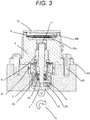
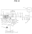
- a part surrounded by a dashed line is the body of a high-pressure fuel supply pump (hereinafter, referred to as a high-pressure pump) .
- the mechanism and parts in the dashed line are integrally embedded in a high-pressure pump body 1.
- the fuel in a fuel tank 20 is pumped up by a feed pump 21, and fed via an intake pipe 28 to an intake joint 10a of the pump body 1.
- the fuel After passing through the intake joint 10a, the fuel passes through a pressure pulsation reducing mechanism 9, and an intake path 10b, and reaches an intake port 30a of an electromagnetic inlet valve 30 included in a flow rate control mechanism.
- the pulsation preventing mechanism 9 will be described below.
- the electromagnetic inlet valve 30 includes an electromagnetic coil 308.
- the electromagnetic coil 308 does not conduct electricity, the difference between the biasing force of an anchor spring 303 and the biasing force of a valve spring 304 biases an inlet valve body 301 in a valve-opening direction in which the inlet valve body 301 is opened, and this opens the intake opening 30d.
- the biasing force of the anchor spring 303 and the biasing force of the valve spring 304 are set so that the biasing force of the anchor spring 303 > the biasing force of the valve spring 304 holds.
- the inlet valve body 301 is still opened by the biasing force of the anchor spring 303.
- the volume of the pressurizing chamber 11 decreases with the compressing motion of the plunger 2.
- the fuel sucked in the pressurizing chamber 11 is returned through the opened inlet valve body 301 to the intake path 10b (the intake port 30a).
- the pressure in the pressurizing chamber is not increased. This process is referred to as a return process.
- ECU engine control unit 27
- a current flows through the electromagnetic coil 308 of the electromagnetic inlet valve 30.
- the magnetic biasing force moves the electromagnetic plunger 305 to the left side of FIG. 4 and a state in which the anchor spring 303 is compressed is maintained.
- the biasing force of the anchor spring 303 does not act on the inlet valve body 301.
- the fluid force due to the biasing force of the valve spring 304 and the flow of the fuel into the intake path 10b (the intake port 30a) acts. This closes the inlet valve 301 and thus closes the intake opening 30d.
- the compression process of the plunger 2 includes the return process and the discharge process.
- Controlling the timing at which the electromagnetic coil 308 of the electromagnetic inlet valve 30 conducts electricity can control the amount of the high-pressure fuel to be discharged.
- the timing at which the electromagnetic coil 308 conducts electricity is hastened, the proportion of the return process is low and the proportion of the discharge process is high to the compression process.
- the amount of fuel to be returned to the intake path 10b (the intake port 30a) is decreased and the amount of fuel to be discharged at high pressure is increased.
- the proportion of the return process is high and the proportion of the discharge process is low to the compression process. In other words, the amount of fuel to be returned to the intake path 10b is increased and the amount of fuel to be discharged at high pressure is decreased.
- the timing at which the electromagnetic coil 308 conducts electricity is controlled by the instructions from the ECU.
- the configuration described above controls the timing at which the electromagnetic coil 308 conducts electricity. This can control the amount of fuel to be discharged at high pressure in accordance with the amount of fuel that the internal-combustion engine requires.
- the outlet of the pressurizing chamber 11 is provided with a discharge valve mechanism 8.
- the discharge valve mechanism 8 includes a discharge valve seat 8a, a discharge valve 8b, and a discharge valve spring 8c.
- the discharge valve 8b When there is no fuel differential pressure between the pressurizing chamber 11 and the discharge joint 12, the discharge valve 8b is pressed and fixed to the discharge valve seat 8a and closed by the biasing force of the discharge valve spring 8c.
- the discharge valve 8b is opened against the discharge valve spring 8c and the fuel in the pressurizing chamber 11 is discharged at high pressure through the discharge joint 12 to the common rail 23.
- the fuel guided to the intake joint 10a is pressurized at high pressure by the reciprocation of the plunger 2 in the pressurizing chamber 11 of the pump body 1 as much as necessary, and fed from the discharge joint 12 to the common rail 23 by the pressure.
- Injectors 24 for direct injection namely, a direct-injection injectors
- a pressure sensor 26 are attached to the common rail 23.
- the number of the attached direct-injection injectors 24 corresponds to the number of cylinder engines of the internal-combustion engine.
- the direct-injection injectors 24 open and close in accordance with the control signal from the engine control unit (ECU) 27 so as to inject the fuel in the cylinder.
- ECU engine control unit
- the pump body 1 is further provided with a discharge flow path 110 communicating the downstream part of the discharge valve 8b with the pressurizing chamber 11 and bypassing the discharge valve, separately from the discharge flow path.
- the discharge flow path 110 is provided with a pressure relief valve 104 that limits the flow of the fuel only to a direction from the discharge flow path to the pressurizing chamber 11.
- the pressure relief valve 104 is pressed to the pressure relief valve seat 105 by the relief spring 102 that generates pressing force.
- the pressure relief valve 104 moves away from the pressure relief valve seat 105 and opens.
- the pressure relief valve 104 opens and the discharge flow path at the excessive high pressure is returned from the discharge flow path 110 to the pressurizing chamber 11. This protects a high-pressure pipe such as the common rail 23.
- a general high-pressure pump is air-tightly sealed and fixed to the flat surface of a cylinder head 41 of the internal-combustion engine with a flange 1e provided to the pump body 1.
- An O-ring 61 is fitted to the pump body 1 so that the airtightness between the cylinder head and the pump body is retained.
- a cylinder 6 is attached to the pump body 1.
- the cylinder 6 is formed in a cylinder with a bottom on an end so that the cylinder 6 guides the back-and-forth movement of the plunger 2 and the pressurizing chamber 11 is formed in the cylinder 6.
- the pressurizing chamber 11 is provided with a plurality of communication holes 11a so that the pressurizing chamber 11 communicates with the electromagnetic inlet valve 30 configured to feed the fuel and the discharge valve mechanism 8 configured to discharge the fuel from the pressurizing chamber 11 to the discharge path.
- the outer diameter of the cylinder 6 includes a large-diameter part and a small-diameter part.
- the small-diameter part is pressed and inserted in the pump body 1.
- the surface of a width difference 6a between the large-diameter part and the small-diameter part is pressed and fixed to the pump body 1. This prevents the fuel pressurized in the pressurizing chamber 11 from leaking to the low-pressure side.
- the lower end of the plunger 2 is provided with a tappet 3 that converts the rotation movement of a cam 5 attached to a camshaft of the internal-combustion engine into up-and-down movement, and transmits the up-and-down movement to the plunger 2.
- the plunger 2 is pressed and fixed to the tappet 3 through a retainer 15 with a spring 4. This can move (reciprocate) the plunger 2 up and down with the rotation movement of the cam 5.
- a plunger seal 13 held on the lower end of the inner periphery of the seal holder 7 has slidably contact with the outer periphery of the plunger 2 on the lower end of the cylinder 6 in the drawing. This seals the blow-by gap between the plunger 2 and the cylinder 6 and prevents the fuel from leaking to the outside of the pump. Meanwhile, this prevents the lubricant (including engine oil) that smoothly moves a sliding part of the internal-combustion engine from leaking through the blow-by gap into the pump body 1.
- the fuel sucked by the feed pump 21 is fed through the intake joint 10a coupled with the intake pipe 28 to the pump body 1.
- a damper cover 14 is coupled with the pump body 1 and forms a low-pressure fuel chamber 10.
- the fuel passing through the inlet joint 10a flows into the low-pressure fuel chamber 10.
- a fuel filter 102 is attached to the upstream part of the low-pressure fuel chamber 10, for example, while being pressed and inserted in the pump body 1.
- a pressure pulsation reducing mechanism 9 is installed in the low-pressure fuel chamber 10 so that the pressure pulsation reducing mechanism 9 reduces the spread of the pressure pulsation generated in the high-pressure pump to a fuel pipe 28.
- the fuel sucked in the pressurizing chamber 11 is returned through the opened inlet valve body 301 to the intake path 10b (the intake port 30a) under a state in which the flow rate of the fuel is controlled, the fuel returned to the intake path 10b (the intake port 30a) generates the pressure pulsation in the low-pressure fuel chamber 10.
- the pressure pulsation is absorbed and reduced by the expansion and contraction of a metal damper 9a forming the pressure pulsation reducing mechanism 9 provided to the low-pressure fuel chamber 10.
- the metal damper 9a is formed of two corrugated metal disks of which outer peripheries are bonded together. Inert gas such as argon is injected in the metal damper 9a.
- Mounting hardware 9b is configured to fix the metal damper 9a on the inner periphery of the pump body 1.
- the electromagnetic inlet valve 30 is a variable control mechanism that includes the electromagnetic coil 308.
- the electromagnetic inlet valve 30 is connected to the ECU through the terminal 307 and repeats conduction and non-conduction of electricity so as to open and close the inlet valve and control the flow rate of the fuel.
- the biasing force of the anchor spring 303 is transmitted to the inlet valve body 301 through the anchor 305 and the anchor rod 302 integrally formed with the anchor 305.
- the biasing force of the valve spring 304 installed in the inlet valve body is set so that the biasing force of the anchor spring 303 > the biasing force of the valve spring 304 holds.
- the inlet valve body 301 is biased in a valve-opening direction in which the inlet valve body 301 is opened.
- the intake opening 30d is opened.
- the anchor rod 302 has contact with the inlet valve body 301 at a part 302b (in a state illustrated FIG. 1 ).
- the setting for the magnetic biasing force generated by the electricity conduction through the coil 308 is configured to enable the anchor 305 to overcome the biasing force of the anchor spring 303 and be sucked into a stator 306.
- the anchor 303 moves toward the stator 306 (the left side of the drawing) and a stopper 302a formed on an end of the anchor rod 302 has contact with an anchor rod bearing 309 and is seized.
- the clearance is set so that the travel distance of the anchor 301 > the travel distance of the inlet valve body 301 holds.
- the contact part 302b opens between the anchor rod 302 and the inlet valve body 301. As a result, the inlet valve body 301 is biased by the valve spring 304 and the intake opening 30d is closed.
- the electromagnetic inlet valve 30 is fixed to the pump body 1 while an inlet valve seat 310 is hermetically inserted in a tubular boss 1b so that the inlet valve body 301 can seal the intake opening 30d to the pressurizing chamber.
- the intake port 30a is connected to the intake path 10b.
- the discharge valve mechanism 8 is provided with a plurality of discharge paths radially drilled around the sliding axis of the discharge valve body 8b.
- the discharge valve mechanism 8 includes a discharge valve seat member 8a and a discharge valve member 8b.
- the discharge valve seat member 8a is provided with a bearing that can sustain the sliding reciprocation of the discharge valve body 8b at the center of the discharge valve seat member 8a.
- the discharge valve member 8b has the central axis so as to slide with respect to the bearing of the discharge valve seat member 8a, and has a circular contact surface on the outer periphery. The circular contact surface can retain the airtightness by having contact with the discharge valve seat member 8a.
- a discharge valve spring 33 is inserted and held in the discharge valve mechanism 8.
- the discharge valve spring 33 is a coil spring that biases the discharge valve member 8b in a valve-closing direction in which the discharge valve member 8b is closed.
- the discharge valve seat member for example, is pressed, inserted and held in the pump body 1.
- the discharge valve member 8b and the discharge valve spring 33 are further inserted in the pump body 1.
- a sealing plug 17 seals the pump body 1.
- the discharge valve mechanism 8 is formed as described above. The formation causes the discharge valve mechanism 8 to function as a check valve that controls the direction in which the fuel flows.
- a pressure relief valve mechanism 100 includes a pressure relief valve housing 101, a relief spring 102, a relief holder 103, a pressure relief valve 104, and a pressure relief valve seat 105. After the pressure relief valve seat 105 is pressed, inserted and fixed to the pressure relief valve housing 101, the pressure relief valve 104, the relief holder 103, and the relief spring 102 are sequentially inserted. The set load of the relief spring 102 is determined depending on the position at which the pressure relief valve seat is fixed. The valve-opening pressure at which the pressure relief valve 104 is opened is determined depending on the set load of the relief spring 102.
- the pressure relief valve mechanism 100 unitized as described above is fixed to the pump body 1 by the press-insertion of the pressure relief valve seat 105 to the inner peripheral wall of a cylindrical pass-through slot 1C provided to the pump body 1. Subsequently, the discharge joint 12 is fixed so that the discharge joint 12 blocks the cylindrical pass-through slot 1C of the pump body 1 so as to prevent the fuel from leaking from the high-pressure pump to the outside and to enable the pressure relief valve mechanism 100 to be connected to a common rail. Meanwhile, the pressure relief valve mechanism 100 is partially stored in the discharge joint 12.
- the discharge valve mechanism 8 and the pressure relief valve mechanism 100 are installed in the pump body so that the central axes of the discharge valve mechanism 8 and the pressure relief valve mechanism 100 are radially arranged around the pressurizing chamber 11. This can make the process easy while the pump body 1 is produced.
- the overshoot generated in the pressurizing chamber will be described with reference to FIG. 5 .
- the pressure in the pressurizing chamber increases with the decrease in volume.
- the discharge valve mechanism 8 is opened and the fuel is discharged from the pressurizing chamber 11 to the discharge flow path 110. From the moment the discharge valve mechanism 8 is opened to the time immediately after the opening, the pressure in the pressurizing chamber overshoots and becomes very high. The very high pressure propagates in the discharge flow path and the pressure in the discharge flow path simultaneously overshoots.
- the overshoot of the pressure in the discharge flow path causes the pressure difference between the inlet and outlet of the pressure relief valve 104 to exceed the valve-opining pressure at which the pressure relief valve mechanism 100 is opened. This causes an error in the pressure relief valve.
- the outlet of the pressure relief valve mechanism 100 of the embodiment is connected to the pressurizing chamber 11, and thus the pressure in the pressurizing chamber acts on the outlet of the pressure relief valve mechanism 100 and the pressure in the discharge flow path 110 acts on the inlet of the pressure relief valve mechanism 11.
- the pressure overshoot occurs simultaneously in the pressurizing chamber and the discharge flow path.
- the pressures difference between the inlet and outlet of the pressure relief valve does not exceed the valve-opining pressure at which the pressure relief valve is opened. In other words, an error in the pressure relief valve does not occur.
- the direct-injection injector In the event of failure of the direct-injection injector, in other words, when the injection function of the direct-injection injector stops and the direct-injection injector does not feed the fuel fed in the common rail 23 into the combustion chamber of the internal-combustion engine, the fuel accumulates between the discharge valve mechanism 8 and the common rail 23. This causes an excessive high pressure of the fuel. When the fuel pressure moderately increases to the excessive high pressure, the pressure sensor 26 provided to the common rail 23 detects the abnormal pressure. Then, the electromagnetic inlet valve 30 that is a flow rate control mechanism provided in the intake path the intake path 10b (the intake port 30a) is controlled by feedback control. The feedback control operates as a safety function to decrease the amount of the fuel to be discharged.
- the feedback control with the pressure sensor is not effective in dealing with an instantaneous excessive high pressure.
- the electromagnetic inlet valve 30 is out of order and keeps the maximum flow rate in an operation state in which the fuel is not required so much, the pressure at which the fuel is discharged excessively increases. In such a case, the excessive high pressure is not dissolved because of the failure of the flow rate control mechanism even when the pressure sensor 26 of the common rail 23 detects the excessive high pressure.
- the pressure relief valve mechanism 100 of the embodiment functions as a safety valve.
- the pressure in the pressurizing chamber decreases with the increase in volume.
- the pressure in the inlet of the pressure relief valve mechanism 100 namely, in the discharge flow path is higher than or equal to the pressure in the outlet of the pressure relief valve, namely, in the pressurizing chamber 11 by the valve-opening pressure at which the pressure relief valve mechanism 100 is opened
- the pressure relief valve mechanism 100 is opened and returns the fuel at an excessive high pressure in the common rail to the pressurizing chamber. This return prevents the fuel pressure from being higher than or equal to a predetermined pressure even when an excessive high pressure occurs. This prevention protects the high-pressure pipe system including the common rail 23.
- the mechanism described above prevents the pressure difference between the inlet and outlet of the pressure relief valve mechanism 100 from being higher than or equal to the valve-opening pressure at which the pressure relief valve mechanism 100 is opened, and thus, the pressure relief valve mechanism 100 is not opened in the discharge process.
- the fuel pressure in the pressurizing chamber 11 decreases to a low pressure identical to the pressure in the intake pipe 28.
- the pressure in the relief chamber 112 increases to a pressure identical to the pressure in the common rail 23.
- a pressure relief valve mechanism 100 provided to a pump body 1 communicates the downstream part of a discharge valve 8b with an intake path 10b.
- a pressure relief valve 104 is pressed to a pressure relief valve seat 105 by a relief spring 102 generating pressing force.
- the pressure relief valve 104 moves away from the pressure relief valve seat 105 and opens.
- a pressure relief valve mechanism 100 includes a pressure relief valve stopper 101, a pressure relief valve 102, a pressure relief valve seat 103, a relief spring stopper 104, and a relief spring 105 as illustrated.
- the pressure relief valve seat 103 includes a bearing that enables the pressure relief valve 102 to slide.
- the pressure relief valve 102 integrally including a sliding shaft is inserted in the pressure relief valve seat 103. After that the position of the relief spring stopper 104 is determined so that the relief spring 105 has a desired load, and the relief spring stopper 104 is fixed to the pressure relief valve 102, for example, by press and insertion.
- the valve-opening pressure at which the pressure relief valve 102 is opened is determined depending on the pressing force of the relief spring 105.
- the pressure relief valve stopper 101 is inserted between the pump body 1 and the pressure relief valve seat 103 so as to function as a stopper that controls how much the pressure relief valve 102 is opened.
- the pressure relief valve mechanism 100 unitized as described above is fixed to the pump body 1 by the press and insertion of the pressure relief valve seat 103 to the inner peripheral wall of a cylindrical pass-through slot 1C provided to the pump body 1.
- the pressure relief valve is an inward-opening valve.
- the relief spring 105 is provided on a side of the pressure relief valve 102 facing the discharge joint 12 as described above. This prevents the increase in volume of the pressurizing chamber 11 even when the outlet of the pressure relief valve 104 of the pressure relief valve mechanism 100 is opened toward the pressurizing chamber 11.
Claims (5)
- Pompe de carburant à haute pression comprenant :deux cages pour une première et une seconde valve, formées dans un corps de pompe (1) ;une valve de décharge (8b) placée dans la première cage de valve ;une valve de détente de pression (104) placée dans la seconde cage de valve et agencée dans un joint de décharge (12) qui stocke partiellement le mécanisme de valve de détente de pression et qui est connectée à un tube à haute pression ; etdes ressorts qui sollicitent la valve de décharge (8b) et la valve de détente de pression (104) vers des sièges de valve, respectivement.
- Pompe à haute pression selon la revendication 1, comprenant en outre : un bouchon qui scelle le trou d'attachement de mécanisme de valve dans lequel la valve de décharge (8b) et le ressort qui sollicite la valve de décharge (8b) sont stockés.
- Pompe à haute pression selon la revendication 2, comprenant en outre : un trajet de décharge formé dans un boîtier de pompe, le trajet de décharge étant configuré pour connecter un trajet à haute pression d'une partie aval de la valve de décharge (8b) à une partie aval de la valve de détente de pression.
- Pompe à haute pression selon la revendication 1, dans laquelle un axe central de la valve de décharge (8b) et un axe central de la valve de détente de pression (104) sont agencés radialement autour d'une chambre de pressurisation.
- Pompe à haute pression selon la revendication 1, dans lequel la valve de détente de pression (104) est une valve qui s'ouvre vers l'intérieur.
Priority Applications (1)
| Application Number | Priority Date | Filing Date | Title |
|---|---|---|---|
| EP19186498.2A EP3587790B1 (fr) | 2014-04-25 | 2015-04-17 | Pompe d'alimentation en carburant haute pression |
Applications Claiming Priority (2)
| Application Number | Priority Date | Filing Date | Title |
|---|---|---|---|
| JP2014090822 | 2014-04-25 | ||
| PCT/JP2015/061776 WO2015163245A1 (fr) | 2014-04-25 | 2015-04-17 | Pompe d'alimentation en carburant à haute pression |
Related Child Applications (1)
| Application Number | Title | Priority Date | Filing Date |
|---|---|---|---|
| EP19186498.2A Division EP3587790B1 (fr) | 2014-04-25 | 2015-04-17 | Pompe d'alimentation en carburant haute pression |
Publications (3)
| Publication Number | Publication Date |
|---|---|
| EP3135901A1 EP3135901A1 (fr) | 2017-03-01 |
| EP3135901A4 EP3135901A4 (fr) | 2018-01-03 |
| EP3135901B1 true EP3135901B1 (fr) | 2019-07-31 |
Family
ID=54332411
Family Applications (2)
| Application Number | Title | Priority Date | Filing Date |
|---|---|---|---|
| EP19186498.2A Active EP3587790B1 (fr) | 2014-04-25 | 2015-04-17 | Pompe d'alimentation en carburant haute pression |
| EP15783842.6A Active EP3135901B1 (fr) | 2014-04-25 | 2015-04-17 | Pompe d'alimentation en carburant à haute pression |
Family Applications Before (1)
| Application Number | Title | Priority Date | Filing Date |
|---|---|---|---|
| EP19186498.2A Active EP3587790B1 (fr) | 2014-04-25 | 2015-04-17 | Pompe d'alimentation en carburant haute pression |
Country Status (5)
| Country | Link |
|---|---|
| US (1) | US10941741B2 (fr) |
| EP (2) | EP3587790B1 (fr) |
| JP (2) | JP6470267B2 (fr) |
| CN (2) | CN111322187B (fr) |
| WO (1) | WO2015163245A1 (fr) |
Families Citing this family (8)
| Publication number | Priority date | Publication date | Assignee | Title |
|---|---|---|---|---|
| CN109072845B (zh) * | 2016-04-06 | 2021-07-30 | 日立汽车系统株式会社 | 高压燃料供给泵 |
| JP6569589B2 (ja) * | 2016-04-28 | 2019-09-04 | 株式会社デンソー | 高圧ポンプ |
| WO2017203861A1 (fr) | 2016-05-27 | 2017-11-30 | 日立オートモティブシステムズ株式会社 | Pompe d'alimentation en carburant haute pression |
| CN109937297A (zh) * | 2016-11-18 | 2019-06-25 | 日立汽车系统株式会社 | 高压燃料供给泵 |
| JP6897173B2 (ja) * | 2017-03-07 | 2021-06-30 | 株式会社デンソー | 高圧ポンプ |
| JP6809520B2 (ja) * | 2017-09-29 | 2021-01-06 | 株式会社デンソー | 高圧ポンプ |
| JP7397729B2 (ja) | 2020-03-18 | 2023-12-13 | 日立Astemo株式会社 | 燃料ポンプ |
| CN112648120A (zh) * | 2020-12-23 | 2021-04-13 | 南岳电控(衡阳)工业技术股份有限公司 | 一种装叶片式输油泵的单缸共轨供油泵 |
Family Cites Families (39)
| Publication number | Priority date | Publication date | Assignee | Title |
|---|---|---|---|---|
| DE7925377U1 (de) * | 1979-09-07 | 1979-12-06 | Robert Bosch Gmbh, 7000 Stuttgart | Kraftstoffeinspritzpumpe fuer brennkraftmaschinen |
| JPS5641157U (fr) * | 1979-09-07 | 1981-04-16 | ||
| IT1150318B (it) * | 1981-03-21 | 1986-12-10 | Bosch Gmbh Robert | Pompa di iniezione del carburante per motori endotermici |
| DE3141654A1 (de) * | 1981-10-21 | 1983-05-05 | L'Orange GmbH, 7000 Stuttgart | Kraftstoffeinspritzpumpe, insbesondere fuer eine dieselbrennkraftmaschine |
| DE3218960A1 (de) * | 1982-05-19 | 1983-11-24 | Speck Kolbenpumpen Fabrik | Pumpe, insbesondere hochdruckpumpe zur foerderung von fluessigkeiten |
| JPH0341089Y2 (fr) * | 1987-04-18 | 1991-08-29 | ||
| JPH116475A (ja) * | 1997-06-18 | 1999-01-12 | Unisia Jecs Corp | 燃料加圧用ポンプ |
| DE10327411B4 (de) * | 2002-10-15 | 2015-12-17 | Robert Bosch Gmbh | Druckbegrenzungsventil sowie Kraftstoffsystem mit einem solchen Druckbegrenzungsventil |
| JP2004218547A (ja) * | 2003-01-15 | 2004-08-05 | Bosch Automotive Systems Corp | 高圧燃料ポンプ |
| JP4415884B2 (ja) * | 2005-03-11 | 2010-02-17 | 株式会社日立製作所 | 電磁駆動機構,電磁弁機構及び電磁駆動機構によって操作される吸入弁を備えた高圧燃料供給ポンプ,電磁弁機構を備えた高圧燃料供給ポンプ |
| JP2007120492A (ja) * | 2005-09-29 | 2007-05-17 | Denso Corp | 高圧燃料ポンプ |
| JP4415929B2 (ja) * | 2005-11-16 | 2010-02-17 | 株式会社日立製作所 | 高圧燃料供給ポンプ |
| JP4437552B2 (ja) * | 2006-05-26 | 2010-03-24 | 株式会社デンソー | 高圧燃料ポンプ |
| JP2008057451A (ja) * | 2006-08-31 | 2008-03-13 | Hitachi Ltd | 高圧燃料供給ポンプ |
| JP2008064013A (ja) * | 2006-09-07 | 2008-03-21 | Hitachi Ltd | 高圧燃料供給ポンプ |
| JP4353288B2 (ja) * | 2007-08-08 | 2009-10-28 | トヨタ自動車株式会社 | 燃料ポンプ |
| JP4413260B2 (ja) * | 2007-10-12 | 2010-02-10 | 株式会社日本自動車部品総合研究所 | 高圧燃料ポンプ |
| JP2009103008A (ja) | 2007-10-22 | 2009-05-14 | Toyota Motor Corp | 燃料ポンプ |
| JP4945504B2 (ja) * | 2008-04-17 | 2012-06-06 | 日立オートモティブシステムズ株式会社 | 高圧燃料供給ポンプ |
| JP5002523B2 (ja) * | 2008-04-25 | 2012-08-15 | 日立オートモティブシステムズ株式会社 | 燃料の圧力脈動低減機構、及びそれを備えた内燃機関の高圧燃料供給ポンプ |
| JP5252314B2 (ja) | 2008-12-26 | 2013-07-31 | 株式会社デンソー | 高圧ポンプ |
| IT1396473B1 (it) * | 2009-03-30 | 2012-12-14 | Magneti Marelli Spa | Pompa carburante con una valvola di massima pressione perfezionata per un sistema di iniezione diretta |
| JP5493966B2 (ja) * | 2009-06-02 | 2014-05-14 | 株式会社デンソー | 燃料噴射装置 |
| IT1396142B1 (it) | 2009-11-03 | 2012-11-16 | Magneti Marelli Spa | Pompa carburante con dispositivo smorzatore perfezionato per un sistema di iniezione diretta |
| KR101526375B1 (ko) * | 2009-11-11 | 2015-06-08 | 현대자동차 주식회사 | 고압 연료 펌프의 토출 밸브와 압력 릴리프 밸브 일체형 구조 |
| US8132558B2 (en) * | 2009-12-01 | 2012-03-13 | Stanadyne Corporation | Common rail fuel pump with combined discharge and overpressure relief valves |
| DE102010001880A1 (de) * | 2010-02-12 | 2011-08-18 | Robert Bosch GmbH, 70469 | Zylinderkopf für eine Kraftstoffhochdruckpumpe |
| JP5226712B2 (ja) * | 2010-02-26 | 2013-07-03 | ヤンマー株式会社 | 燃料噴射ポンプ |
| JP5401360B2 (ja) * | 2010-02-26 | 2014-01-29 | 日立オートモティブシステムズ株式会社 | 高圧燃料供給ポンプ |
| KR101182131B1 (ko) * | 2010-08-23 | 2012-09-12 | (주)모토닉 | 직접분사식 가솔린 엔진용 고압연료펌프 |
| JP5501272B2 (ja) | 2011-03-08 | 2014-05-21 | 日立オートモティブシステムズ株式会社 | 高圧燃料供給ポンプ |
| JP5472751B2 (ja) * | 2011-03-30 | 2014-04-16 | 株式会社デンソー | 高圧ポンプ |
| US9181944B2 (en) | 2011-03-31 | 2015-11-10 | Denso Corporation | High pressure pump having unitary discharge and relief valve |
| JP5653288B2 (ja) * | 2011-04-27 | 2015-01-14 | 株式会社デンソー | 定残圧弁 |
| JP5639970B2 (ja) * | 2011-08-03 | 2014-12-10 | 日立オートモティブシステムズ株式会社 | 電磁弁の制御方法、高圧燃料供給ポンプの電磁吸入弁の制御方法および電磁吸入弁の電磁駆動機構の制御装置 |
| ES2865184T3 (es) * | 2011-11-17 | 2021-10-15 | Stanadyne Llc | Válvula de alivio de presión auxiliar en bomba de combustible de un solo pistón |
| CN105008709B (zh) * | 2013-03-05 | 2018-04-20 | 斯坦蒂内有限责任公司 | 电控式入口计量单活塞燃油泵 |
| JP2014224523A (ja) * | 2013-04-18 | 2014-12-04 | 株式会社デンソー | 弁装置、及びこの弁装置を用いる高圧ポンプ |
| JP5589121B2 (ja) | 2013-06-06 | 2014-09-10 | 日立オートモティブシステムズ株式会社 | 高圧燃料供給ポンプ |
-
2015
- 2015-04-17 EP EP19186498.2A patent/EP3587790B1/fr active Active
- 2015-04-17 WO PCT/JP2015/061776 patent/WO2015163245A1/fr active Application Filing
- 2015-04-17 EP EP15783842.6A patent/EP3135901B1/fr active Active
- 2015-04-17 CN CN202010084729.7A patent/CN111322187B/zh active Active
- 2015-04-17 US US15/304,237 patent/US10941741B2/en active Active
- 2015-04-17 CN CN201580021052.XA patent/CN106232978B/zh active Active
- 2015-04-17 JP JP2016514898A patent/JP6470267B2/ja active Active
-
2019
- 2019-01-17 JP JP2019005751A patent/JP6860598B2/ja active Active
Non-Patent Citations (1)
| Title |
|---|
| None * |
Also Published As
| Publication number | Publication date |
|---|---|
| JPWO2015163245A1 (ja) | 2017-04-13 |
| CN111322187A (zh) | 2020-06-23 |
| JP6860598B2 (ja) | 2021-04-14 |
| EP3135901A4 (fr) | 2018-01-03 |
| EP3587790B1 (fr) | 2023-03-08 |
| EP3587790A1 (fr) | 2020-01-01 |
| WO2015163245A1 (fr) | 2015-10-29 |
| CN106232978B (zh) | 2020-02-28 |
| JP6470267B2 (ja) | 2019-02-13 |
| US10941741B2 (en) | 2021-03-09 |
| JP2019074092A (ja) | 2019-05-16 |
| CN106232978A (zh) | 2016-12-14 |
| EP3135901A1 (fr) | 2017-03-01 |
| US20170037822A1 (en) | 2017-02-09 |
| CN111322187B (zh) | 2021-12-31 |
Similar Documents
| Publication | Publication Date | Title |
|---|---|---|
| EP3135901B1 (fr) | Pompe d'alimentation en carburant à haute pression | |
| JP4415929B2 (ja) | 高圧燃料供給ポンプ | |
| EP2803851B1 (fr) | Pompe à carburant à haute pression de moteur à combustion interne | |
| EP2497939B1 (fr) | Pompe d'alimentation en carburant haute pression | |
| EP3135900B1 (fr) | Pompe d'alimentation en carburant à haute pression | |
| JP6561158B2 (ja) | 電磁弁、この電磁弁を吸入弁機構として備えた高圧燃料供給ポンプ | |
| JP5589121B2 (ja) | 高圧燃料供給ポンプ | |
| CN110832188B (zh) | 高压燃料泵 | |
| EP3135899B1 (fr) | Pompe à carburant à haute pression | |
| WO2018012211A1 (fr) | Pompe d'alimentation en carburant à haute pression | |
| US20220316470A1 (en) | Fuel Pump | |
| JP2018105274A (ja) | 高圧燃料供給ポンプ | |
| JP2017160915A (ja) | 高圧燃料供給ポンプ | |
| JP6165674B2 (ja) | 高圧燃料供給ポンプ | |
| EP4286680A1 (fr) | Mécanisme de vanne électromagnétique et pompe à carburant | |
| EP4191049A1 (fr) | Pompe à carburant | |
| EP4286718A1 (fr) | Pompe à carburant | |
| US20230193865A1 (en) | Fuel Pump | |
| JP2023030297A (ja) | 燃料ポンプ | |
| JP2021188544A (ja) | 燃料ポンプ | |
| JP2017072027A (ja) | 高圧燃料供給ポンプ | |
| JP2019027334A (ja) | 高圧燃料供給ポンプ | |
| JP2018009495A (ja) | 高圧燃料供給ポンプ |
Legal Events
| Date | Code | Title | Description |
|---|---|---|---|
| STAA | Information on the status of an ep patent application or granted ep patent |
Free format text: STATUS: THE INTERNATIONAL PUBLICATION HAS BEEN MADE |
|
| PUAI | Public reference made under article 153(3) epc to a published international application that has entered the european phase |
Free format text: ORIGINAL CODE: 0009012 |
|
| STAA | Information on the status of an ep patent application or granted ep patent |
Free format text: STATUS: REQUEST FOR EXAMINATION WAS MADE |
|
| 17P | Request for examination filed |
Effective date: 20161125 |
|
| AK | Designated contracting states |
Kind code of ref document: A1 Designated state(s): AL AT BE BG CH CY CZ DE DK EE ES FI FR GB GR HR HU IE IS IT LI LT LU LV MC MK MT NL NO PL PT RO RS SE SI SK SM TR |
|
| AX | Request for extension of the european patent |
Extension state: BA ME |
|
| DAV | Request for validation of the european patent (deleted) | ||
| DAX | Request for extension of the european patent (deleted) | ||
| RIC1 | Information provided on ipc code assigned before grant |
Ipc: F02M 63/00 20060101ALI20171123BHEP Ipc: F02M 59/46 20060101AFI20171123BHEP Ipc: F02M 59/34 20060101ALI20171123BHEP Ipc: F02M 59/44 20060101ALI20171123BHEP Ipc: F02M 59/48 20060101ALI20171123BHEP |
|
| A4 | Supplementary search report drawn up and despatched |
Effective date: 20171130 |
|
| GRAP | Despatch of communication of intention to grant a patent |
Free format text: ORIGINAL CODE: EPIDOSNIGR1 |
|
| STAA | Information on the status of an ep patent application or granted ep patent |
Free format text: STATUS: GRANT OF PATENT IS INTENDED |
|
| INTG | Intention to grant announced |
Effective date: 20190207 |
|
| GRAS | Grant fee paid |
Free format text: ORIGINAL CODE: EPIDOSNIGR3 |
|
| GRAA | (expected) grant |
Free format text: ORIGINAL CODE: 0009210 |
|
| STAA | Information on the status of an ep patent application or granted ep patent |
Free format text: STATUS: THE PATENT HAS BEEN GRANTED |
|
| AK | Designated contracting states |
Kind code of ref document: B1 Designated state(s): AL AT BE BG CH CY CZ DE DK EE ES FI FR GB GR HR HU IE IS IT LI LT LU LV MC MK MT NL NO PL PT RO RS SE SI SK SM TR |
|
| REG | Reference to a national code |
Ref country code: CH Ref legal event code: EP Ref country code: GB Ref legal event code: FG4D |
|
| RIN1 | Information on inventor provided before grant (corrected) |
Inventor name: SUGANAMI MASAYUKI Inventor name: TOKUO KENICHIROU Inventor name: YAMADA HIROYUKI Inventor name: SAITO ATSUJI Inventor name: YAGAI MASAMICHI Inventor name: USUI SATOSHI Inventor name: SASO YUTA Inventor name: HOHKITA ATSUSHI |
|
| REG | Reference to a national code |
Ref country code: DE Ref legal event code: R096 Ref document number: 602015034871 Country of ref document: DE |
|
| REG | Reference to a national code |
Ref country code: AT Ref legal event code: REF Ref document number: 1161164 Country of ref document: AT Kind code of ref document: T Effective date: 20190815 |
|
| REG | Reference to a national code |
Ref country code: IE Ref legal event code: FG4D |
|
| REG | Reference to a national code |
Ref country code: NL Ref legal event code: MP Effective date: 20190731 |
|
| REG | Reference to a national code |
Ref country code: LT Ref legal event code: MG4D |
|
| REG | Reference to a national code |
Ref country code: AT Ref legal event code: MK05 Ref document number: 1161164 Country of ref document: AT Kind code of ref document: T Effective date: 20190731 |
|
| PG25 | Lapsed in a contracting state [announced via postgrant information from national office to epo] |
Ref country code: FI Free format text: LAPSE BECAUSE OF FAILURE TO SUBMIT A TRANSLATION OF THE DESCRIPTION OR TO PAY THE FEE WITHIN THE PRESCRIBED TIME-LIMIT Effective date: 20190731 Ref country code: HR Free format text: LAPSE BECAUSE OF FAILURE TO SUBMIT A TRANSLATION OF THE DESCRIPTION OR TO PAY THE FEE WITHIN THE PRESCRIBED TIME-LIMIT Effective date: 20190731 Ref country code: SE Free format text: LAPSE BECAUSE OF FAILURE TO SUBMIT A TRANSLATION OF THE DESCRIPTION OR TO PAY THE FEE WITHIN THE PRESCRIBED TIME-LIMIT Effective date: 20190731 Ref country code: NO Free format text: LAPSE BECAUSE OF FAILURE TO SUBMIT A TRANSLATION OF THE DESCRIPTION OR TO PAY THE FEE WITHIN THE PRESCRIBED TIME-LIMIT Effective date: 20191031 Ref country code: AT Free format text: LAPSE BECAUSE OF FAILURE TO SUBMIT A TRANSLATION OF THE DESCRIPTION OR TO PAY THE FEE WITHIN THE PRESCRIBED TIME-LIMIT Effective date: 20190731 Ref country code: LT Free format text: LAPSE BECAUSE OF FAILURE TO SUBMIT A TRANSLATION OF THE DESCRIPTION OR TO PAY THE FEE WITHIN THE PRESCRIBED TIME-LIMIT Effective date: 20190731 Ref country code: PT Free format text: LAPSE BECAUSE OF FAILURE TO SUBMIT A TRANSLATION OF THE DESCRIPTION OR TO PAY THE FEE WITHIN THE PRESCRIBED TIME-LIMIT Effective date: 20191202 Ref country code: NL Free format text: LAPSE BECAUSE OF FAILURE TO SUBMIT A TRANSLATION OF THE DESCRIPTION OR TO PAY THE FEE WITHIN THE PRESCRIBED TIME-LIMIT Effective date: 20190731 Ref country code: BG Free format text: LAPSE BECAUSE OF FAILURE TO SUBMIT A TRANSLATION OF THE DESCRIPTION OR TO PAY THE FEE WITHIN THE PRESCRIBED TIME-LIMIT Effective date: 20191031 |
|
| PG25 | Lapsed in a contracting state [announced via postgrant information from national office to epo] |
Ref country code: IS Free format text: LAPSE BECAUSE OF FAILURE TO SUBMIT A TRANSLATION OF THE DESCRIPTION OR TO PAY THE FEE WITHIN THE PRESCRIBED TIME-LIMIT Effective date: 20191130 Ref country code: GR Free format text: LAPSE BECAUSE OF FAILURE TO SUBMIT A TRANSLATION OF THE DESCRIPTION OR TO PAY THE FEE WITHIN THE PRESCRIBED TIME-LIMIT Effective date: 20191101 Ref country code: ES Free format text: LAPSE BECAUSE OF FAILURE TO SUBMIT A TRANSLATION OF THE DESCRIPTION OR TO PAY THE FEE WITHIN THE PRESCRIBED TIME-LIMIT Effective date: 20190731 Ref country code: LV Free format text: LAPSE BECAUSE OF FAILURE TO SUBMIT A TRANSLATION OF THE DESCRIPTION OR TO PAY THE FEE WITHIN THE PRESCRIBED TIME-LIMIT Effective date: 20190731 Ref country code: AL Free format text: LAPSE BECAUSE OF FAILURE TO SUBMIT A TRANSLATION OF THE DESCRIPTION OR TO PAY THE FEE WITHIN THE PRESCRIBED TIME-LIMIT Effective date: 20190731 Ref country code: RS Free format text: LAPSE BECAUSE OF FAILURE TO SUBMIT A TRANSLATION OF THE DESCRIPTION OR TO PAY THE FEE WITHIN THE PRESCRIBED TIME-LIMIT Effective date: 20190731 |
|
| PG25 | Lapsed in a contracting state [announced via postgrant information from national office to epo] |
Ref country code: TR Free format text: LAPSE BECAUSE OF FAILURE TO SUBMIT A TRANSLATION OF THE DESCRIPTION OR TO PAY THE FEE WITHIN THE PRESCRIBED TIME-LIMIT Effective date: 20190731 |
|
| PG25 | Lapsed in a contracting state [announced via postgrant information from national office to epo] |
Ref country code: IT Free format text: LAPSE BECAUSE OF FAILURE TO SUBMIT A TRANSLATION OF THE DESCRIPTION OR TO PAY THE FEE WITHIN THE PRESCRIBED TIME-LIMIT Effective date: 20190731 Ref country code: DK Free format text: LAPSE BECAUSE OF FAILURE TO SUBMIT A TRANSLATION OF THE DESCRIPTION OR TO PAY THE FEE WITHIN THE PRESCRIBED TIME-LIMIT Effective date: 20190731 Ref country code: EE Free format text: LAPSE BECAUSE OF FAILURE TO SUBMIT A TRANSLATION OF THE DESCRIPTION OR TO PAY THE FEE WITHIN THE PRESCRIBED TIME-LIMIT Effective date: 20190731 Ref country code: RO Free format text: LAPSE BECAUSE OF FAILURE TO SUBMIT A TRANSLATION OF THE DESCRIPTION OR TO PAY THE FEE WITHIN THE PRESCRIBED TIME-LIMIT Effective date: 20190731 Ref country code: PL Free format text: LAPSE BECAUSE OF FAILURE TO SUBMIT A TRANSLATION OF THE DESCRIPTION OR TO PAY THE FEE WITHIN THE PRESCRIBED TIME-LIMIT Effective date: 20190731 |
|
| PG25 | Lapsed in a contracting state [announced via postgrant information from national office to epo] |
Ref country code: SK Free format text: LAPSE BECAUSE OF FAILURE TO SUBMIT A TRANSLATION OF THE DESCRIPTION OR TO PAY THE FEE WITHIN THE PRESCRIBED TIME-LIMIT Effective date: 20190731 Ref country code: CZ Free format text: LAPSE BECAUSE OF FAILURE TO SUBMIT A TRANSLATION OF THE DESCRIPTION OR TO PAY THE FEE WITHIN THE PRESCRIBED TIME-LIMIT Effective date: 20190731 Ref country code: SM Free format text: LAPSE BECAUSE OF FAILURE TO SUBMIT A TRANSLATION OF THE DESCRIPTION OR TO PAY THE FEE WITHIN THE PRESCRIBED TIME-LIMIT Effective date: 20190731 Ref country code: IS Free format text: LAPSE BECAUSE OF FAILURE TO SUBMIT A TRANSLATION OF THE DESCRIPTION OR TO PAY THE FEE WITHIN THE PRESCRIBED TIME-LIMIT Effective date: 20200224 |
|
| REG | Reference to a national code |
Ref country code: DE Ref legal event code: R097 Ref document number: 602015034871 Country of ref document: DE |
|
| PLBE | No opposition filed within time limit |
Free format text: ORIGINAL CODE: 0009261 |
|
| STAA | Information on the status of an ep patent application or granted ep patent |
Free format text: STATUS: NO OPPOSITION FILED WITHIN TIME LIMIT |
|
| PG2D | Information on lapse in contracting state deleted |
Ref country code: IS |
|
| PG25 | Lapsed in a contracting state [announced via postgrant information from national office to epo] |
Ref country code: IS Free format text: LAPSE BECAUSE OF FAILURE TO SUBMIT A TRANSLATION OF THE DESCRIPTION OR TO PAY THE FEE WITHIN THE PRESCRIBED TIME-LIMIT Effective date: 20191030 |
|
| 26N | No opposition filed |
Effective date: 20200603 |
|
| PG25 | Lapsed in a contracting state [announced via postgrant information from national office to epo] |
Ref country code: SI Free format text: LAPSE BECAUSE OF FAILURE TO SUBMIT A TRANSLATION OF THE DESCRIPTION OR TO PAY THE FEE WITHIN THE PRESCRIBED TIME-LIMIT Effective date: 20190731 |
|
| PG25 | Lapsed in a contracting state [announced via postgrant information from national office to epo] |
Ref country code: MC Free format text: LAPSE BECAUSE OF FAILURE TO SUBMIT A TRANSLATION OF THE DESCRIPTION OR TO PAY THE FEE WITHIN THE PRESCRIBED TIME-LIMIT Effective date: 20190731 |
|
| REG | Reference to a national code |
Ref country code: CH Ref legal event code: PL |
|
| PG25 | Lapsed in a contracting state [announced via postgrant information from national office to epo] |
Ref country code: FR Free format text: LAPSE BECAUSE OF NON-PAYMENT OF DUE FEES Effective date: 20200430 Ref country code: LI Free format text: LAPSE BECAUSE OF NON-PAYMENT OF DUE FEES Effective date: 20200430 Ref country code: CH Free format text: LAPSE BECAUSE OF NON-PAYMENT OF DUE FEES Effective date: 20200430 Ref country code: LU Free format text: LAPSE BECAUSE OF NON-PAYMENT OF DUE FEES Effective date: 20200417 |
|
| REG | Reference to a national code |
Ref country code: BE Ref legal event code: MM Effective date: 20200430 |
|
| PG25 | Lapsed in a contracting state [announced via postgrant information from national office to epo] |
Ref country code: BE Free format text: LAPSE BECAUSE OF NON-PAYMENT OF DUE FEES Effective date: 20200430 |
|
| REG | Reference to a national code |
Ref country code: DE Ref legal event code: R082 Ref document number: 602015034871 Country of ref document: DE Representative=s name: MERH-IP MATIAS ERNY REICHL HOFFMANN PATENTANWA, DE Ref country code: DE Ref legal event code: R081 Ref document number: 602015034871 Country of ref document: DE Owner name: HITACHI ASTEMO, LTD., HITACHINAKA-SHI, JP Free format text: FORMER OWNER: HITACHI AUTOMOTIVE SYSTEMS, LTD., HITACHINAKA-SHI, IBARAKI, JP |
|
| GBPC | Gb: european patent ceased through non-payment of renewal fee |
Effective date: 20200417 |
|
| PG25 | Lapsed in a contracting state [announced via postgrant information from national office to epo] |
Ref country code: GB Free format text: LAPSE BECAUSE OF NON-PAYMENT OF DUE FEES Effective date: 20200417 Ref country code: IE Free format text: LAPSE BECAUSE OF NON-PAYMENT OF DUE FEES Effective date: 20200417 |
|
| PG25 | Lapsed in a contracting state [announced via postgrant information from national office to epo] |
Ref country code: MT Free format text: LAPSE BECAUSE OF FAILURE TO SUBMIT A TRANSLATION OF THE DESCRIPTION OR TO PAY THE FEE WITHIN THE PRESCRIBED TIME-LIMIT Effective date: 20190731 Ref country code: CY Free format text: LAPSE BECAUSE OF FAILURE TO SUBMIT A TRANSLATION OF THE DESCRIPTION OR TO PAY THE FEE WITHIN THE PRESCRIBED TIME-LIMIT Effective date: 20190731 |
|
| PG25 | Lapsed in a contracting state [announced via postgrant information from national office to epo] |
Ref country code: MK Free format text: LAPSE BECAUSE OF FAILURE TO SUBMIT A TRANSLATION OF THE DESCRIPTION OR TO PAY THE FEE WITHIN THE PRESCRIBED TIME-LIMIT Effective date: 20190731 |
|
| PGFP | Annual fee paid to national office [announced via postgrant information from national office to epo] |
Ref country code: DE Payment date: 20230228 Year of fee payment: 9 |