EP3135566B1 - Structure de construction legere de vehicule automobile de facture souple - Google Patents
Structure de construction legere de vehicule automobile de facture souple Download PDFInfo
- Publication number
- EP3135566B1 EP3135566B1 EP15182959.5A EP15182959A EP3135566B1 EP 3135566 B1 EP3135566 B1 EP 3135566B1 EP 15182959 A EP15182959 A EP 15182959A EP 3135566 B1 EP3135566 B1 EP 3135566B1
- Authority
- EP
- European Patent Office
- Prior art keywords
- vehicle body
- node
- body structure
- section
- structures
- Prior art date
- Legal status (The legal status is an assumption and is not a legal conclusion. Google has not performed a legal analysis and makes no representation as to the accuracy of the status listed.)
- Active
Links
- 238000004519 manufacturing process Methods 0.000 title claims description 37
- 238000010276 construction Methods 0.000 title description 16
- 239000000463 material Substances 0.000 claims description 48
- 238000000034 method Methods 0.000 claims description 19
- 239000000654 additive Substances 0.000 claims description 15
- 230000000996 additive effect Effects 0.000 claims description 13
- 238000003466 welding Methods 0.000 claims description 10
- 229910052751 metal Inorganic materials 0.000 claims description 8
- 239000002184 metal Substances 0.000 claims description 8
- 239000000843 powder Substances 0.000 claims description 8
- 238000000110 selective laser sintering Methods 0.000 claims description 7
- 230000008018 melting Effects 0.000 claims description 5
- 238000002844 melting Methods 0.000 claims description 5
- 238000013461 design Methods 0.000 description 7
- 238000011161 development Methods 0.000 description 7
- 230000018109 developmental process Effects 0.000 description 7
- XAGFODPZIPBFFR-UHFFFAOYSA-N aluminium Chemical compound [Al] XAGFODPZIPBFFR-UHFFFAOYSA-N 0.000 description 6
- RTAQQCXQSZGOHL-UHFFFAOYSA-N Titanium Chemical compound [Ti] RTAQQCXQSZGOHL-UHFFFAOYSA-N 0.000 description 5
- 229910052782 aluminium Inorganic materials 0.000 description 5
- 238000005457 optimization Methods 0.000 description 5
- 239000010959 steel Substances 0.000 description 5
- 239000010936 titanium Substances 0.000 description 5
- 229910052719 titanium Inorganic materials 0.000 description 5
- 229910000831 Steel Inorganic materials 0.000 description 4
- 238000003032 molecular docking Methods 0.000 description 4
- 229910000838 Al alloy Inorganic materials 0.000 description 2
- XEEYBQQBJWHFJM-UHFFFAOYSA-N Iron Chemical compound [Fe] XEEYBQQBJWHFJM-UHFFFAOYSA-N 0.000 description 2
- 229910001069 Ti alloy Inorganic materials 0.000 description 2
- 229910045601 alloy Inorganic materials 0.000 description 2
- 239000000956 alloy Substances 0.000 description 2
- 238000005266 casting Methods 0.000 description 2
- 239000002131 composite material Substances 0.000 description 2
- 238000000465 moulding Methods 0.000 description 2
- 235000001968 nicotinic acid Nutrition 0.000 description 2
- 230000002787 reinforcement Effects 0.000 description 2
- 238000010146 3D printing Methods 0.000 description 1
- 229910000851 Alloy steel Inorganic materials 0.000 description 1
- 240000000057 Victoria amazonica Species 0.000 description 1
- 230000006978 adaptation Effects 0.000 description 1
- 238000004026 adhesive bonding Methods 0.000 description 1
- 238000013459 approach Methods 0.000 description 1
- 238000000149 argon plasma sintering Methods 0.000 description 1
- 210000000988 bone and bone Anatomy 0.000 description 1
- 238000005253 cladding Methods 0.000 description 1
- 238000004590 computer program Methods 0.000 description 1
- 238000007796 conventional method Methods 0.000 description 1
- 230000001419 dependent effect Effects 0.000 description 1
- 230000008021 deposition Effects 0.000 description 1
- 239000003814 drug Substances 0.000 description 1
- 238000005516 engineering process Methods 0.000 description 1
- 239000000835 fiber Substances 0.000 description 1
- 238000003780 insertion Methods 0.000 description 1
- 230000037431 insertion Effects 0.000 description 1
- 238000009434 installation Methods 0.000 description 1
- 229910052742 iron Inorganic materials 0.000 description 1
- 230000001788 irregular Effects 0.000 description 1
- 238000005304 joining Methods 0.000 description 1
- 238000005259 measurement Methods 0.000 description 1
- 238000011089 mechanical engineering Methods 0.000 description 1
- 239000007769 metal material Substances 0.000 description 1
- 150000002739 metals Chemical class 0.000 description 1
Images


Classifications
-
- B—PERFORMING OPERATIONS; TRANSPORTING
- B62—LAND VEHICLES FOR TRAVELLING OTHERWISE THAN ON RAILS
- B62D—MOTOR VEHICLES; TRAILERS
- B62D27/00—Connections between superstructure or understructure sub-units
- B62D27/02—Connections between superstructure or understructure sub-units rigid
- B62D27/023—Assembly of structural joints
-
- B—PERFORMING OPERATIONS; TRANSPORTING
- B22—CASTING; POWDER METALLURGY
- B22F—WORKING METALLIC POWDER; MANUFACTURE OF ARTICLES FROM METALLIC POWDER; MAKING METALLIC POWDER; APPARATUS OR DEVICES SPECIALLY ADAPTED FOR METALLIC POWDER
- B22F10/00—Additive manufacturing of workpieces or articles from metallic powder
- B22F10/20—Direct sintering or melting
- B22F10/25—Direct deposition of metal particles, e.g. direct metal deposition [DMD] or laser engineered net shaping [LENS]
-
- B—PERFORMING OPERATIONS; TRANSPORTING
- B22—CASTING; POWDER METALLURGY
- B22F—WORKING METALLIC POWDER; MANUFACTURE OF ARTICLES FROM METALLIC POWDER; MAKING METALLIC POWDER; APPARATUS OR DEVICES SPECIALLY ADAPTED FOR METALLIC POWDER
- B22F10/00—Additive manufacturing of workpieces or articles from metallic powder
- B22F10/20—Direct sintering or melting
- B22F10/28—Powder bed fusion, e.g. selective laser melting [SLM] or electron beam melting [EBM]
-
- B—PERFORMING OPERATIONS; TRANSPORTING
- B22—CASTING; POWDER METALLURGY
- B22F—WORKING METALLIC POWDER; MANUFACTURE OF ARTICLES FROM METALLIC POWDER; MAKING METALLIC POWDER; APPARATUS OR DEVICES SPECIALLY ADAPTED FOR METALLIC POWDER
- B22F5/00—Manufacture of workpieces or articles from metallic powder characterised by the special shape of the product
- B22F5/10—Manufacture of workpieces or articles from metallic powder characterised by the special shape of the product of articles with cavities or holes, not otherwise provided for in the preceding subgroups
-
- B—PERFORMING OPERATIONS; TRANSPORTING
- B62—LAND VEHICLES FOR TRAVELLING OTHERWISE THAN ON RAILS
- B62D—MOTOR VEHICLES; TRAILERS
- B62D21/00—Understructures, i.e. chassis frame on which a vehicle body may be mounted
- B62D21/02—Understructures, i.e. chassis frame on which a vehicle body may be mounted comprising longitudinally or transversely arranged frame members
-
- B—PERFORMING OPERATIONS; TRANSPORTING
- B62—LAND VEHICLES FOR TRAVELLING OTHERWISE THAN ON RAILS
- B62D—MOTOR VEHICLES; TRAILERS
- B62D29/00—Superstructures, understructures, or sub-units thereof, characterised by the material thereof
- B62D29/008—Superstructures, understructures, or sub-units thereof, characterised by the material thereof predominantly of light alloys, e.g. extruded
-
- B—PERFORMING OPERATIONS; TRANSPORTING
- B62—LAND VEHICLES FOR TRAVELLING OTHERWISE THAN ON RAILS
- B62D—MOTOR VEHICLES; TRAILERS
- B62D65/00—Designing, manufacturing, e.g. assembling, facilitating disassembly, or structurally modifying motor vehicles or trailers, not otherwise provided for
- B62D65/02—Joining sub-units or components to, or positioning sub-units or components with respect to, body shell or other sub-units or components
-
- B—PERFORMING OPERATIONS; TRANSPORTING
- B22—CASTING; POWDER METALLURGY
- B22F—WORKING METALLIC POWDER; MANUFACTURE OF ARTICLES FROM METALLIC POWDER; MAKING METALLIC POWDER; APPARATUS OR DEVICES SPECIALLY ADAPTED FOR METALLIC POWDER
- B22F10/00—Additive manufacturing of workpieces or articles from metallic powder
- B22F10/80—Data acquisition or data processing
-
- Y—GENERAL TAGGING OF NEW TECHNOLOGICAL DEVELOPMENTS; GENERAL TAGGING OF CROSS-SECTIONAL TECHNOLOGIES SPANNING OVER SEVERAL SECTIONS OF THE IPC; TECHNICAL SUBJECTS COVERED BY FORMER USPC CROSS-REFERENCE ART COLLECTIONS [XRACs] AND DIGESTS
- Y02—TECHNOLOGIES OR APPLICATIONS FOR MITIGATION OR ADAPTATION AGAINST CLIMATE CHANGE
- Y02P—CLIMATE CHANGE MITIGATION TECHNOLOGIES IN THE PRODUCTION OR PROCESSING OF GOODS
- Y02P10/00—Technologies related to metal processing
- Y02P10/25—Process efficiency
Definitions
- the invention relates to a lightweight vehicle structure, in particular a function-integrated, lightweight hybrid vehicle structure in flexible production.
- the construction according to the invention can be used in vehicles, in particular motor vehicles.
- the construction method and the production concept shown can also be used on bodies or components for heavy and light commercial vehicles, mobile work machines or in general for space frame structures or for rod-node structures for machines and systems and advantageously for the areas of passenger vehicles and commercial vehicles , Rail vehicles, mechanical engineering, aircraft and space technology, medicine, etc.
- a body node for connecting shell-shaped body structures of a vehicle is known.
- a base wall structure and a reinforcement rib of the body node are formed together as a thin-walled metal cast body in a casting process.
- the US 2011/061591 A1 describes a manufacturing method and a device for the generative manufacture of a three-dimensional component. With the method and the device, vehicle components can be produced generatively.
- the EP 2 801 512 A1 discloses a composite structure with a base structure that forms a body node of a vehicle body, and a generatively shaped functional structure that mechanically reinforces the body node or the base structure, so that overall a highly resilient, lightweight composite structure is obtained.
- the EP 0 146 716 A1 shows a body node for connecting body structures of a vehicle, the body node having a first, second and third connecting flange for a connection to the body structure and a connecting structure which rigidly connects the connecting bottle to one another and with which it forms a monolithic body.
- Generative manufacturing processes as such are known to those skilled in the art, such as B. laser additive manufacturing processes (LAM), in particular selective laser melting (SLM) and selective laser sintering (SLS).
- LAM laser additive manufacturing processes
- SLM selective laser melting
- SLS selective laser sintering
- the invention is based on the object of specifying a vehicle node, a body section of a body and a manufacturing method for the body node or the body section, the body node or the body section to be improved structurally, in particular with regard to lightweight construction and stability.
- the invention is based on a body node for connecting, in particular shell-shaped body structures of a vehicle, in particular a motor vehicle.
- the body node is preferably part of a self-supporting structure of a vehicle, in particular in a space frame or framework construction.
- a shell-shaped body structure is considered to be a body structure that has a thin-walled structure, such as a wall or sheet metal, which is angled or curved at least once, such as several times, in cross section, such as in cross section transverse to the longitudinal direction of the body structure and / or has a closed or open cross section.
- the body node is adapted to absorb forces and moments of the body structures attached to it or connected to it.
- the body node connects the body structures attached to it, for. B. rigid.
- the example shell-shaped body structures can preferably be elongated, idealized from the point of view of technical mechanics, for. B. be viewed as bars or beams. At least one, several or all of the body structures mentioned herein can be designed in the shape of a shell or box. Under a box-shaped body structure that A special case of a shell-shaped body structure is understood to be a tubular or prismatic, in particular thin-walled, hollow profile which surrounds a cavity at least over the largest part of its circumference. Although the shell-shaped or box-shaped body structure preferably has a closed cross section, it can in principle also have an open cross-section, wherein the shell-shaped or box-shaped body structure can enclose the cavity on at least three, preferably four sides.
- the body structure can be angled one or more times over its circumference.
- the body structure can have a regular or irregular prismatic or tubular shape.
- the body structure has high torsional and torsional rigidity.
- At least one, several or each of the body structures can be an extruded profile or a profile composed of one or more metal sheets.
- a profile preferably forms the said shell-shaped or box-shaped body structure.
- the shell-shaped or box-shaped body structure by means of a generative manufacturing process or another primary forming process, such as. B. a casting process.
- a body structure can be produced in one of the named designs and another body structure in another of the named designs.
- the body node has a first connection flange for connection to a first body structure and at least one further connection flange for connection to at least one further body structure.
- the body node has a first connection flange for a connection to a first body structure, a second connection flange for a connection to a second body structure and a third Connection flange for connection to a third body structure.
- the term connection also includes fastening, that is to say that the connection flange is provided for fastening to the respective body structure.
- the body node can have a fourth or even a fifth or generally an n-th connecting flange for a connection to a fourth, fifth or n-th body structure. The number of connecting flanges results from the requirement of how many body structures are to be connected to the body node.
- the body node comprises a connection structure which rigidly connects the connecting flanges of the body node to one another.
- the connection structure together with the connection flanges of the body node forms a monolithic, i.e. H. one-piece body which can advantageously be handled as a single body.
- the body node could also consist of several parts, such as. B. cast and / or sheet metal parts, which are rigidly connected to each other and thus also form an individually manageable unit.
- the body node has been or is produced generatively by means of a laser-additive manufacturing method, such as a selective laser melting method or a selective laser sintering method.
- a laser-additive manufacturing method such as a selective laser melting method or a selective laser sintering method.
- any generative manufacturing method can be used to generate the body node.
- a synonym for generative molding or manufacturing can also be referred to as additive molding or manufacturing.
- the entire body node including the connection structure and the connection flanges is preferably formed generatively or additively by means of a laser.
- Laser additive manufacturing includes the processes of "Direct Metal Laser Sintering" (DMLS), "Selective Laser Melting” (SLM), “Laser Cusing", “Selective Laser Sintering” (SLS) or laser generation.
- DMLS Direct Metal Laser Sintering
- SLM Selective Laser Melting
- SLS Selective Laser Sintering
- the range of materials includes in particular metallic materials, such as. B. iron or steel, aluminum and titanium alloys, but is not limited to this because the materials or alloys that can be provided for this purpose are constantly being expanded.
- the structure node can be produced by means of additive manufacturing from a plastic material, in particular a structurally relevant plastic material, with or without fiber reinforcement.
- the process is based on a 3D CAD model of the component to be produced, in particular the structure node.
- the component to be manufactured is placed in a virtual installation space, broken down into individual layers and saved as layer information. Typical layer thicknesses are depending on the material and the manufacturing plant z. B. between 30 and 60 micrometers, but can also be above or below.
- the actual manufacturing process can e.g. B. comprise three basic, iteratively repeating steps up to component completion. In a first step, a thin powder layer corresponding to the current component layer is melted by the laser. In a second step the powder bed is then lowered by one layer thickness and in a third step a further powder layer is applied to the component layer solidified by the laser.
- Additive manufacturing can be adapted to the fluctuating number of units of the vehicle variants with a low level of logistics effort.
- the structure nodes can e.g. B. On site for the respective variant "Just in Sequence" can be produced.
- the body structures can also be manufactured or cut accordingly shortly before production. It should also be emphasized that during a vehicle life cycle it is quick and easy to respond to new functional requirements, e.g. B. can be responded to by updateable structural components, in particular the structure node.
- connection structure can have at least one topologically optimized section or can be topologically optimized.
- the aim of the optimization is, in particular, that the body node has high strength and low weight (lightweight construction).
- the topologically optimized structure or the topologically optimized section can e.g. B. contain struts or beams, which may resemble the structure of the interior of a bird bone or a Victoria lily.
- the beams or struts can be arranged in a cavity which is surrounded by an enveloping wall of the connecting structure.
- the enveloping wall can be provided with depressions and / or recesses or holes.
- the beams or struts in the cavity surrounded by the wall stiffen the wall and open into it.
- the struts or beams can also branch out.
- Additive manufacturing allows the beams or struts to be optimized with regard to the load cases to be expected that act on the structure nodes, in particular in terms of their mechanical stability.
- the body node can therefore be optimized so that it only has material there where it is needed so as not to fail with the expected loads.
- Such optimizations are z. B. made using numerical methods on a CAD model of the component to be manufactured.
- the wall surrounding the cavity preferably connects the connecting flanges of the body node.
- the beams or struts in the cavity can also connect the connecting flanges, but it is preferred that the beams or struts stiffen the wall. Additive manufacturing allows such a topologically optimized design of the connection structure.
- the body structures or at least one of the body structures which are elongated and form a rod or beam in the space frame, also generatively, with the, in particular box-shaped, cross section being optionally with depressions and / or Circumferential wall provided with holes can surround a cavity in which bars or struts are arranged which open into the wall and thus stiffen the wall, it being preferred that these bars or struts are topologically optimized with regard to lightweight construction.
- At least one, several or each of the connecting flanges can each form an enclosure which encloses the body structure provided for the connecting flange on the outer circumference.
- an end region, in particular of an elongated body structure is framed on the outer circumference.
- the end of the body structure can be inserted into the enclosure.
- the enclosure can the connecting flange z. B. completely or partially surrounded over the outer circumference.
- At least one, several or each of the connecting flanges can form a base on which the body structure provided for the connecting flange, in particular an end region or one end of the body structure, can be slipped or slipped.
- the outer circumference of the end region of the body structure can thus partially or completely surround the base over its circumference.
- the body node can, for. B. one or more Have connecting flanges that form a base and one or more connecting flanges that form an enclosure.
- the enclosure or the base can e.g. B. at least be shaped or be that a, preferably elongated, body structure can be secured or is secured positively against movements transverse to the longitudinal direction or longitudinal axis of the body structure and optionally also positively against rotation in the longitudinal direction or around the longitudinal axis of the body structure, if the body structure is arranged in the enclosure or on the base.
- the end of the body structure can thus have a non-circular cross-section, which prevents the body structure from rotating in the longitudinal direction or about the longitudinal axis of the body structure.
- the enclosure can e.g. B. have one or more tabs which secure the end of the body structure positively against movements transversely to the longitudinal axis or direction of the body structure and / or positively against rotation about the longitudinal axis or direction.
- an end edge of the enclosure or enclosure formed by the enclosure and pointing away from the connecting structure can run at least in sections at an angle to the circumferential direction of the enclosure or enclosure. It can thereby be achieved that the entire length of the end edge of the enclosure or enclosure is greater than the circumference of the enclosure or enclosure.
- a weld seam by means of which the connecting flange or the surround or surround is cohesively joined to the end area or the outer circumference of the end area of the body structure, preferably in the lap joint, can be made longer than the circumference. This increases the stability of the connection between the connecting flange and the body structure.
- the weld seam can preferably be a fillet weld.
- the end region of an elongated body structure inserted into the enclosure or on the base is joined to the flange, in particular the enclosure or the base, with a material fit by means of a weld seam, in particular a fillet weld.
- connection structure has a first material and at least one of the connection flanges has a different or different type of second material from the first material, the end to be fastened to the connection flange or the end region of the body structure to be fastened being made of a material which is similar to the second material and in particular is different from the first material.
- a high-strength or extremely high-strength first material such as, for. B. a steel material can be selected, wherein a material can be selected for the connection flanges, which can be cohesively joined, in particular welded, with the material of the to be fastened or the fastened end of the connection structure, in particular by welding.
- the second material and / or the material e.g. B. the end of the body structure be an aluminum material.
- the first material can be an aluminum material and the second material and / or the material of the end of the body structure to be fastened can be a steel material.
- Other material combinations also appear possible, such as B: 1. Material 2. Material Aluminum material Titanium material Titanium material Titanium material Aluminum material Steel material Titanium material Titanium material Steel material
- the body node in particular the connection structure, can be a docking point, such as B. have a standardized docking point or two-hole docking point for inclusion by an industrial robot.
- the industrial robot can the body node z. B. for joining with the body structures at the docking point and handle accordingly.
- the body node can of course be joined to the body structure by hand or, preferably, by means of industrial robots.
- a robot can pick up the body node, with a further robot or robot arm picking up the, for example, shell-shaped body structure and inserting the end of the body structure into the enclosure or on the base.
- the robot can have a combination head.
- the end of the body structure can also be applied in a tight fit that is provided by the surround or the base.
- the connecting flange can be joined to the body structure by means of the robot or another robot.
- At least one elongate body structure can be arranged across one or more other body structures.
- a first body structure can be transverse to the vehicle longitudinal axis or along the vehicle transverse axis
- a second body structure along the vehicle longitudinal axis
- a third body structure along the vehicle vertical axis or along the Extend vehicle longitudinal axis.
- a fourth body structure can be provided with a fourth connecting flange of the body node and z.
- B. extend along the vertical axis of the vehicle or along the longitudinal axis of the vehicle.
- An extension along the longitudinal axis of the vehicle is not necessarily understood to mean an extension parallel to the longitudinal axis of the vehicle, but also an extension of the longitudinal direction or longitudinal axis of the body structure at least partially along the named axis.
- the body node can be arranged in the area of the A, B, C or D pillar of the vehicle body.
- the body node can be arranged on the floor, on the roof or between the floor and the roof.
- the body node can also be used at points other than those mentioned in the body, in particular at the points where several body structures converge and z. B. be joined with high strength.
- At least one, several or each of the named body structures can be selected from the group of the following: cross member, longitudinal member, in particular front longitudinal member and rear longitudinal member, rocker panel, roof-side cross rail, bonnet support, windshield root, A-pillar, in particular upper A-pillar and lower A-pillar, B-pillar, C-pillar, D-pillar.
- the body section or body can have a first body node, which can be configured as described herein, and a second body node, which can be configured as described herein.
- the first body node can be connected to the second body node via one of the body structures mentioned, in particular such that the first body node is attached to a first end of the body structure and the second body node is attached to a second end of the body structure.
- the first body node and the second body node can be arranged on different sides of the vehicle or body be or be arranged on the same side of the vehicle or body, but in different longitudinal positions or height positions.
- the components can be welded by means of a fillet weld in or on the lap joint.
- the enclosure or the base of the profiles is also referred to as shoeing.
- the end of the body structure can be about 5 to 20 mm, especially e.g. B. 10 mm depth in the enclosure or on the base.
- This connection enables circumferential welding for a large connection length with good pre-positioning of the components at the same time. Tolerance compensation is also possible through this type of connection.
- the body structures are automatically, i. H. by the given geometry of the base, aligned and fixed by the body node, d. H. in particular against translatory movements transverse to the longitudinal axis or longitudinal direction and rotational movements around the longitudinal axis or direction.
- the body structures can have deviations from the desired contour, an adaptation of the connecting flange for which the corresponding body structure is provided can be provided.
- the permissible gap size of z. B. a maximum of 0.2 mm for laser welding.
- the actual geometry including the actual dimensions is determined for at least one, several or each of the body structures.
- a deviation from the target geometry, including the target dimensions of the respective body structure can be determined. This can e.g. B. be done by means of laser measurement or scanning.
- the actual geometry including the actual dimensions are taken over as data from the CAD program (computer program) and transmitted to the production machine in the form of control and / or geometry data.
- the machine then produces the connecting flange provided for the individual body structure to match the determined actual geometry, including the actual dimensions, using a generative manufacturing process.
- the one for the body structures provided connecting flanges can, for. B. be formed together with the body node, in particular as a monolithic body.
- the self-supporting body in particular the space frame
- it can, for. B. be measured.
- the contact surfaces for built-in and add-on parts, such as B. cockpit or cladding elements, can be glued or welded or printed in the next step for the respective component on the profiles or nodes, such. B. with a 3D printing process or a generative manufacturing process as mentioned herein.
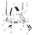
- Figure 1 shows a body section 100 by way of example in the area of the left A-pillar of a body for a motor vehicle.
- the body section 100 has a first body node 1 and a second body node 2 for connecting, for example, shell-shaped body structures 4, 5, 6, 7, 8, 9, 10.
- the first body node 1 and the second body node 2 are geometrically different, but have a similar structure in terms of their function and the corresponding functional elements. A reference to details of the first body node 1 therefore also applies accordingly to a reference to the second body node 2 and vice versa.
- the first body node 1 has a first connection flange 13a for fastening a shell-shaped first connection structure 6, namely a front longitudinal member, a second connection flange 13b for fastening a shell-shaped second body structure 8, namely a cross member which runs transversely to the vehicle or body longitudinal axis and in particular connects a corresponding or essentially mirror-inverted body node on the right side of the vehicle to body node 1 on the left side of the vehicle, and a third connecting flange 13c for attaching a shell-shaped third body structure 7, in particular a lower A-pillar.
- the third body structure 7 connects the second body node 2 to the first body node 1 and extends approximately in the direction of the vertical axis of the body.
- the body node 1 also has a fourth connecting flange 13d for fastening a shell-shaped fourth body structure 9, which extends approximately parallel to the longitudinal axis of the body and can in particular be a rocker.
- the second body node 2 has a first connecting flange 13e for attaching a shell-shaped first body structure 4, in particular a hood support, which extends forward along the longitudinal axis of the body, downward along the vertical axis and inward along the transverse axis.
- the body node 2 comprises a second connection flange 13f for the attachment of a shell-shaped second body structure 5, in particular a disk root extending along the transverse axis of the body.
- the body node 2 has a third connecting flange 13g for fastening a shell-shaped third body structure 7, in particular a lower part of the A-pillar that extends along the vertical axis of the body.
- the body node 2 has a fourth connecting flange 13h for fastening a shell-shaped fourth body structure 10, in particular one extending along the longitudinal axis of the body to the rear and along the body vertical axis upwardly extending upper part of the A-pillar.
- the body structures 4, 5, 6, 7, 8, 9, 10 shown are attached to their connecting flanges 13a to 13h provided for this purpose by means of welds 18 (cf. Figure 3 ) firmly attached.
- the welds 18 can, for. B. be manufactured by means of laser welding or are.
- the connecting flanges 13a to 13d can be connected via a connecting structure 17 which comprises a wall enveloping a cavity 16.
- the enveloping wall can have several recesses or openings 15.
- a plurality of struts 14 which open into the wall enveloping the cavity 16 and are encompassed by the connection structure 17 are arranged.
- the connecting structure 17 including its wall enclosing the cavity 16 and the struts 14 is topologically optimized, in particular with regard to a lightweight construction, i.e. H. for the highest possible strength with the lowest possible weight.
- the topologically optimized structure can be determined by numerical processes and produced using a generative manufacturing process.
- connection structure 17 of the first body node 1 also apply analogously to the second body node 2, even if the geometry differs from that of the first body node 1.
- the connecting flanges 13a to 13d have an enclosure or enclosure 12, which can also be referred to as a boot, which forms a wall running completely around the circumference.
- the respective enclosure 12 of the flanges 13a to 13d enclose corresponding body structures 6, 7, 8, 9 over their outer circumference, in particular tightly, such as. B. with a maximum gap size of less or equal to 0.3 mm or less than or equal to 0.2 mm.
- the end of the corresponding body structure 6, 7, 8, 9 is inserted into the flange 13a to 13d, the border 12 being welded in the lap joint with the outer circumference of the end region of the body structure 6, 7, 8, 9, in particular by means of a partially or completely circumferential weld seam 18, in particular a fillet weld.
- the body structure 6, 7, 8, 9 cannot be moved transversely to its longitudinal axis, or can not move significantly, ie apart from play due to the gap which is necessary for inserting the body structure 6 , 7, 8, 9 in the flange 13a to 13d is required.
- each of the flanges 13a to 13g has an inwardly protruding shoulder which forms an axial stop for the body structure 4 to 10 assigned to the flange 13a to 13g and in particular a maximum depth of insertion of the body structure 4 to 10 into the flange 13a to 13a 13g establishes or defines.
- the first body node 1 has two flanges 13c and the second body node 2 has two flanges 13g.
- the body nodes 1 and 2 are connected via two shell-shaped or box-shaped body structures 7, in particular formed as an extruded profile.
- One of the body structures 7 connects one of the connecting flanges 13c to one of the connecting flanges 13g, the other body structure 7 connecting the other connecting flange 13c to the other connecting flange 13g.
- the first body node 1 and / or the second body node 2 can have a tab 11 which projects from the outside of the body or the body section 100 and which is part of a Joint or hinge for a door to be attached in the later course of the vehicle assembly, in the example shown the driver's door in left-hand drive vehicles or the passenger door in right-hand drive vehicles.
- the bracket 11 has a bore which is in particular aligned with the bore of the bracket 11 of the other body node 1.
- the tab 11 can, for. B. in the production of the body node 1, 2 with this generatively shaped or subsequently attached to the connecting structure 17 of the body node 1, 2, such as. B. by welding, gluing or by screws or another non-positive or positive connection element.
Landscapes
- Engineering & Computer Science (AREA)
- Chemical & Material Sciences (AREA)
- Mechanical Engineering (AREA)
- Combustion & Propulsion (AREA)
- Transportation (AREA)
- Manufacturing & Machinery (AREA)
- Materials Engineering (AREA)
- Physics & Mathematics (AREA)
- Plasma & Fusion (AREA)
- Architecture (AREA)
- Structural Engineering (AREA)
- Body Structure For Vehicles (AREA)
Claims (14)
- Noeud de carrosserie (1, 2) destiné à relier des structures de carrosserie (6, 7, 8, 9, 4, 5, 7, 10), en particulier en forme de coque, d'un véhicule, le nœud de carrosserie (1, 2) comprenant :- une première bride de liaison (13a, 13e) pour une liaison à une première structure de carrosserie (6, 4),- une deuxième bride de liaison (13b, 13f) pour une liaison à une deuxième structure de carrosserie (8, 5),- une troisième bride de liaison (13c, 13g) pour une liaison à une troisième structure de carrosserie (7) et- une structure de liaison (17) qui relie les brides de liaison (13a, 13b, 13c, 13d, 13e, 13f, 13g) de manière rigide les unes aux autres et, avec les brides de liaison (13a, 13b, 13c, 13d, 13e, 13f, 13g), forme de préférence un corps monolithique,le nœud de carrosserie (1, 2) est fabriqué de manière générative à l'aide d'un des procédés suivants :
caractérisé en ce que- fusion sélective par laser (SLM),- frittage sélectif au laser (SLS),- fusion directe par laser (DMLS),- génération au laser,- procédé de fabrication additive au laser (LAM) ou- soudage au laser par dépôt de poudre,et la structure de liaison (17) présente un premier matériau et au moins une des brides de liaison (13a, 13b, 13c, 13d, 13e, 13f, 13g) présente un second matériau différent du premier matériau, dans lequel l'extrémité de la structure de carrosserie (4, 5, 6, 7, 8, 9, 10) qui doit être fixée à la bride de liaison (13a, 13b, 13c, 13d, 13e, 13f, 13g) est composée d'un matériau qui est équivalent au second matériau et en particulier est différent du premier matériau. - Noeud de carrosserie (1, 2) selon la revendication 1, caractérisé en ce qu'au moins une des brides de liaison (13a, 13b, 13c, 13d, 13e, 13f, 13g) forme une bordure (12) qui borde du côté de la périphérie extérieure la structure de carrosserie (4, 5, 6, 7, 8, 9, 10) prévue pour la bride de liaison (13a, 13b, 13c, 13d, 13e, 13f, 13g), en particulier une zone d'extrémité de la structure de carrosserie (4, 5, 6, 7, 8, 9, 10).
- Noeud de carrosserie (1, 2) selon la revendication 1, caractérisé en ce qu'au moins une des brides de liaison (13a, 13b, 13c, 13d, 13e, 13f, 13g) forme un socle sur lequel est placée la structure de carrosserie (4, 5, 6, 7, 8, 9, 10) prévue pour la bride de liaison (13a, 13b, 13c, 13d, 13e, 13f, 13g), en particulier une zone d'extrémité de la structure de carrosserie (4, 5, 6, 7, 8, 9, 10).
- Noeud de carrosserie (1, 2) selon la revendication 2 ou 3, caractérisé en ce que la bordure (12) ou le socle est formé(e) de telle sorte que la structure de carrosserie (4, 5, 6, 7, 8, 9, 10), de préférence oblongue, peut être bloquée par complémentarité de forme contre tout mouvement transversalement à la direction longitudinale de la structure de carrosserie (4, 5, 6, 7, 8, 9, 10) et en option également par complémentarité de forme contre toute rotation autour de l'axe longitudinal de la structure de carrosserie (4, 5, 6, 7, 8, 9, 10) .
- Noeud de carrosserie (1, 2) selon la revendication 2 ou 4, caractérisé en ce qu'un bord d'extrémité de la bordure (12) formé par la bordure (12) et éloigné de la structure de liaison (17) s'étend au moins par sections de manière de manière olbique par rapport à la direction périphérique de la bordure (12) .
- Noeud de carrosserie (1, 2) selon une des revendications précédentes, caractérisé en ce que la structure de liaison (17) présente au moins une section topologiquement optimisée ou est topologiquement optimisée afin que par exemple le nœud de carrosserie (1, 2) présente une résistance élevée avec un poids faible.
- Section de carrosserie (100) pour une carrosserie, par exemple monocoque ou ayant la forme d'un châssis en treillis, d'un véhicule, en particulier d'un véhicule automobile, ou un cadre de châssis en treillis (spaceframe), dans laquelle la section de carrosserie (100) présente au moins un nœud de carrosserie (1, 2) selon une des revendications précédentes et plusieurs structures de carrosserie (6, 7, 8, 9, 4, 5, 10), en particulier en forme de coque, dans laquelle- la première structure de carrosserie (6, 4) est fixée à la première bride de liaison (13a, 13f),- la deuxième structure de carrosserie (8, 5) est fixée à la deuxième bride de liaison (13b, 13f) et- la troisième structure de carrosserie (7) est fixée à la troisième bride de liaison (13c, 13g).
- Section de carrosserie (100) selon la revendication précédente, caractérisée en ce qu'au moins une des structures de carrosserie (4, 5, 6, 7, 8, 9, 10) a une forme de caisse, en particulier est réalisée avec une section fermée et/ou oblongue.
- Section de carrosserie (100) selon une des deux revendications précédentes, caractérisée en ce qu'au moins une des structures de carrosserie (4, 5, 6, 7, 8, 9, 10) est un profilé extrudé ou un profilé composé d'une ou de plusieurs tôles.
- Section de carrosserie (100) selon une des trois revendications précédentes, caractérisée en ce qu'au moins une structure de carrosserie oblongue (4, 5, 6, 7, 8, 9, 10) est disposée transversalement à une ou à plusieurs autres structures de carrosserie (4, 5, 6, 7, 8, 9, 10).
- Section de carrosserie (100) selon une des quatre revendications précédentes, caractérisée en ce qu'au moins une ou l'ensemble desdites structures de carrosserie (4, 5, 6, 7, 8, 9, 10) sont choisies dans le groupe constitué des structures suivantes :- renfort de capot (4),- base de vitre (5),- support longitudinal (6),- colonne A (7),- colonne B,- colonne C,- support transversal (8) ou- pièce d'appui (9).
- Section de carrosserie (100) selon une des cinq revendications précédentes, caractérisée en ce qu'au moins une des structures de carrosserie (4, 5, 6, 7, 8, 9, 10) est assemblé avec le nœud de carrosserie (1, 2) par liaison de matière, en particulier est soudée, dans laquelle il est préféré que le cordon de soudure soit plus long que la périphérie de la structure de carrosserie (4, 5, 6, 7, 8, 9, 10).
- Section de carrosserie (100) selon une des six revendications précédentes, caractérisée par un premier nœud de carrosserie (1), qui est réalisé selon une des revendications 1 à 6, et un second nœud de carrosserie (2), qui est réalisé selon une des revendications 1 à 6, le premier nœud de carrosserie (1) étant relié au second nœud de carrosserie (2) par le biais d'une des structures de carrosserie (7), en particulier de telle sorte que le premier nœud de carrosserie (1) soit fixé à une première extrémité de la structure de carrosserie (7) et le deuxième nœud de carrosserie (2) à une seconde extrémité de la structure de carrosserie (7).
- Procédé de fabrication d'un nœud de carrosserie (1, 2) selon une des revendications 1 à 6, comprenant les étapes suivantes :- fourniture d'une première structure de carrosserie (6, 4), d'une deuxième structure de carrosserie (8, 5) et d'une troisième structure de carrosserie (7), dans lequel la géométrie réelle y compris les dimensions réelles sont déterminées d'au moins une des structures de carrosserie (4, 5, 6, 7, 8, 9, 10) et la bride de liaison (13a à 13h) prévue pour la structure de carrosserie (4, 5, 6, 7, 8, 9, 10) est formée de manière générative de manière s'adapter à la géométrie réelle déterminée, y compris les dimensions réelles, en particulier conjointement avec le nœud de carrosserie (1, 2).
Priority Applications (2)
| Application Number | Priority Date | Filing Date | Title |
|---|---|---|---|
| EP15182959.5A EP3135566B1 (fr) | 2015-08-28 | 2015-08-28 | Structure de construction legere de vehicule automobile de facture souple |
| US15/248,798 US10286961B2 (en) | 2015-08-28 | 2016-08-26 | Lightweight vehicle structure flexibly manufactured |
Applications Claiming Priority (1)
| Application Number | Priority Date | Filing Date | Title |
|---|---|---|---|
| EP15182959.5A EP3135566B1 (fr) | 2015-08-28 | 2015-08-28 | Structure de construction legere de vehicule automobile de facture souple |
Publications (2)
| Publication Number | Publication Date |
|---|---|
| EP3135566A1 EP3135566A1 (fr) | 2017-03-01 |
| EP3135566B1 true EP3135566B1 (fr) | 2020-11-25 |
Family
ID=54014582
Family Applications (1)
| Application Number | Title | Priority Date | Filing Date |
|---|---|---|---|
| EP15182959.5A Active EP3135566B1 (fr) | 2015-08-28 | 2015-08-28 | Structure de construction legere de vehicule automobile de facture souple |
Country Status (2)
| Country | Link |
|---|---|
| US (1) | US10286961B2 (fr) |
| EP (1) | EP3135566B1 (fr) |
Families Citing this family (93)
| Publication number | Priority date | Publication date | Assignee | Title |
|---|---|---|---|---|
| KR20170019366A (ko) | 2014-05-16 | 2017-02-21 | 디버전트 테크놀로지스, 인크. | 차량 섀시용 모듈형 성형 접속체 및 그 사용 방법 |
| US10960929B2 (en) | 2014-07-02 | 2021-03-30 | Divergent Technologies, Inc. | Systems and methods for vehicle subassembly and fabrication |
| SG10201806531QA (en) * | 2014-07-02 | 2018-09-27 | Divergent Technologies Inc | Systems and methods for fabricating joint members |
| DE102016107048B4 (de) * | 2016-04-15 | 2021-06-24 | Saf-Holland Gmbh | Rahmeneinheit |
| CN109311070A (zh) | 2016-06-09 | 2019-02-05 | 戴弗根特技术有限公司 | 用于弧形件和节点的设计和制造的系统及方法 |
| US10759090B2 (en) | 2017-02-10 | 2020-09-01 | Divergent Technologies, Inc. | Methods for producing panels using 3D-printed tooling shells |
| US11155005B2 (en) | 2017-02-10 | 2021-10-26 | Divergent Technologies, Inc. | 3D-printed tooling and methods for producing same |
| CN110573754B (zh) * | 2017-03-01 | 2022-07-12 | 福特全球技术公司 | 用于3d打印的车辆架构即接头的组装方法 |
| US10343725B2 (en) * | 2017-03-03 | 2019-07-09 | GM Global Technology Operations LLC | Automotive structural component and method of manufacture |
| US10898968B2 (en) | 2017-04-28 | 2021-01-26 | Divergent Technologies, Inc. | Scatter reduction in additive manufacturing |
| US10703419B2 (en) * | 2017-05-19 | 2020-07-07 | Divergent Technologies, Inc. | Apparatus and methods for joining panels |
| US11358337B2 (en) | 2017-05-24 | 2022-06-14 | Divergent Technologies, Inc. | Robotic assembly of transport structures using on-site additive manufacturing |
| US11123973B2 (en) | 2017-06-07 | 2021-09-21 | Divergent Technologies, Inc. | Interconnected deflectable panel and node |
| US10919230B2 (en) | 2017-06-09 | 2021-02-16 | Divergent Technologies, Inc. | Node with co-printed interconnect and methods for producing same |
| US10781846B2 (en) | 2017-06-19 | 2020-09-22 | Divergent Technologies, Inc. | 3-D-printed components including fasteners and methods for producing same |
| US10994876B2 (en) | 2017-06-30 | 2021-05-04 | Divergent Technologies, Inc. | Automated wrapping of components in transport structures |
| US11022375B2 (en) | 2017-07-06 | 2021-06-01 | Divergent Technologies, Inc. | Apparatus and methods for additively manufacturing microtube heat exchangers |
| US10895315B2 (en) | 2017-07-07 | 2021-01-19 | Divergent Technologies, Inc. | Systems and methods for implementing node to node connections in mechanized assemblies |
| US10940609B2 (en) * | 2017-07-25 | 2021-03-09 | Divergent Technologies, Inc. | Methods and apparatus for additively manufactured endoskeleton-based transport structures |
| US10751800B2 (en) | 2017-07-25 | 2020-08-25 | Divergent Technologies, Inc. | Methods and apparatus for additively manufactured exoskeleton-based transport structures |
| US10605285B2 (en) | 2017-08-08 | 2020-03-31 | Divergent Technologies, Inc. | Systems and methods for joining node and tube structures |
| US10357959B2 (en) | 2017-08-15 | 2019-07-23 | Divergent Technologies, Inc. | Methods and apparatus for additively manufactured identification features |
| US20190054532A1 (en) * | 2017-08-21 | 2019-02-21 | Divergent Technologies, Inc. | Systems and methods for bridging components |
| DE102017119257A1 (de) * | 2017-08-23 | 2019-02-28 | Man Truck & Bus Ag | Tragbock für ein lenkergeführtes Doppelachsaggregat |
| US11306751B2 (en) | 2017-08-31 | 2022-04-19 | Divergent Technologies, Inc. | Apparatus and methods for connecting tubes in transport structures |
| US10960611B2 (en) * | 2017-09-06 | 2021-03-30 | Divergent Technologies, Inc. | Methods and apparatuses for universal interface between parts in transport structures |
| DE202017105474U1 (de) | 2017-09-08 | 2018-12-14 | Edag Engineering Gmbh | Materialoptimierter Verbindungsknoten |
| DE202017105475U1 (de) * | 2017-09-08 | 2018-12-12 | Edag Engineering Gmbh | Generativ gefertigte Batteriehalterung |
| US11292058B2 (en) | 2017-09-12 | 2022-04-05 | Divergent Technologies, Inc. | Apparatus and methods for optimization of powder removal features in additively manufactured components |
| US10814564B2 (en) | 2017-10-11 | 2020-10-27 | Divergent Technologies, Inc. | Composite material inlay in additively manufactured structures |
| US10668816B2 (en) | 2017-10-11 | 2020-06-02 | Divergent Technologies, Inc. | Solar extended range electric vehicle with panel deployment and emitter tracking |
| US11786971B2 (en) | 2017-11-10 | 2023-10-17 | Divergent Technologies, Inc. | Structures and methods for high volume production of complex structures using interface nodes |
| US10926599B2 (en) | 2017-12-01 | 2021-02-23 | Divergent Technologies, Inc. | Suspension systems using hydraulic dampers |
| US11110514B2 (en) | 2017-12-14 | 2021-09-07 | Divergent Technologies, Inc. | Apparatus and methods for connecting nodes to tubes in transport structures |
| US11085473B2 (en) | 2017-12-22 | 2021-08-10 | Divergent Technologies, Inc. | Methods and apparatus for forming node to panel joints |
| US11534828B2 (en) | 2017-12-27 | 2022-12-27 | Divergent Technologies, Inc. | Assembling structures comprising 3D printed components and standardized components utilizing adhesive circuits |
| US11420262B2 (en) | 2018-01-31 | 2022-08-23 | Divergent Technologies, Inc. | Systems and methods for co-casting of additively manufactured interface nodes |
| US10751934B2 (en) | 2018-02-01 | 2020-08-25 | Divergent Technologies, Inc. | Apparatus and methods for additive manufacturing with variable extruder profiles |
| US11224943B2 (en) | 2018-03-07 | 2022-01-18 | Divergent Technologies, Inc. | Variable beam geometry laser-based powder bed fusion |
| US11267236B2 (en) | 2018-03-16 | 2022-03-08 | Divergent Technologies, Inc. | Single shear joint for node-to-node connections |
| US11872689B2 (en) | 2018-03-19 | 2024-01-16 | Divergent Technologies, Inc. | End effector features for additively manufactured components |
| US11254381B2 (en) | 2018-03-19 | 2022-02-22 | Divergent Technologies, Inc. | Manufacturing cell based vehicle manufacturing system and method |
| US11408216B2 (en) | 2018-03-20 | 2022-08-09 | Divergent Technologies, Inc. | Systems and methods for co-printed or concurrently assembled hinge structures |
| US11613078B2 (en) | 2018-04-20 | 2023-03-28 | Divergent Technologies, Inc. | Apparatus and methods for additively manufacturing adhesive inlet and outlet ports |
| US11214317B2 (en) | 2018-04-24 | 2022-01-04 | Divergent Technologies, Inc. | Systems and methods for joining nodes and other structures |
| US11020800B2 (en) | 2018-05-01 | 2021-06-01 | Divergent Technologies, Inc. | Apparatus and methods for sealing powder holes in additively manufactured parts |
| US10682821B2 (en) | 2018-05-01 | 2020-06-16 | Divergent Technologies, Inc. | Flexible tooling system and method for manufacturing of composite structures |
| US11389816B2 (en) | 2018-05-09 | 2022-07-19 | Divergent Technologies, Inc. | Multi-circuit single port design in additively manufactured node |
| US10691104B2 (en) | 2018-05-16 | 2020-06-23 | Divergent Technologies, Inc. | Additively manufacturing structures for increased spray forming resolution or increased fatigue life |
| US11590727B2 (en) | 2018-05-21 | 2023-02-28 | Divergent Technologies, Inc. | Custom additively manufactured core structures |
| DE102018208155B4 (de) * | 2018-05-24 | 2022-07-07 | Bayerische Motoren Werke Aktiengesellschaft | Knotenelement für eine Fahrzeugkarosserie |
| US11441586B2 (en) | 2018-05-25 | 2022-09-13 | Divergent Technologies, Inc. | Apparatus for injecting fluids in node based connections |
| US11035511B2 (en) | 2018-06-05 | 2021-06-15 | Divergent Technologies, Inc. | Quick-change end effector |
| GB201809373D0 (en) | 2018-06-07 | 2018-07-25 | Rolls Royce Plc | A gearbox and a geared gas turbine engine |
| US20190391563A1 (en) * | 2018-06-22 | 2019-12-26 | Divergent Technologies, Inc. | Additive manufacturing-enabled platform for modular construction of vehicles using definition nodes |
| US11292056B2 (en) | 2018-07-06 | 2022-04-05 | Divergent Technologies, Inc. | Cold-spray nozzle |
| US11269311B2 (en) | 2018-07-26 | 2022-03-08 | Divergent Technologies, Inc. | Spray forming structural joints |
| US10836120B2 (en) | 2018-08-27 | 2020-11-17 | Divergent Technologies, Inc . | Hybrid composite structures with integrated 3-D printed elements |
| US11433557B2 (en) | 2018-08-28 | 2022-09-06 | Divergent Technologies, Inc. | Buffer block apparatuses and supporting apparatuses |
| US11826953B2 (en) | 2018-09-12 | 2023-11-28 | Divergent Technologies, Inc. | Surrogate supports in additive manufacturing |
| US11072371B2 (en) | 2018-10-05 | 2021-07-27 | Divergent Technologies, Inc. | Apparatus and methods for additively manufactured structures with augmented energy absorption properties |
| US11260582B2 (en) | 2018-10-16 | 2022-03-01 | Divergent Technologies, Inc. | Methods and apparatus for manufacturing optimized panels and other composite structures |
| US11504912B2 (en) | 2018-11-20 | 2022-11-22 | Divergent Technologies, Inc. | Selective end effector modular attachment device |
| USD911222S1 (en) | 2018-11-21 | 2021-02-23 | Divergent Technologies, Inc. | Vehicle and/or replica |
| US10663110B1 (en) | 2018-12-17 | 2020-05-26 | Divergent Technologies, Inc. | Metrology apparatus to facilitate capture of metrology data |
| US11449021B2 (en) | 2018-12-17 | 2022-09-20 | Divergent Technologies, Inc. | Systems and methods for high accuracy fixtureless assembly |
| US11529741B2 (en) | 2018-12-17 | 2022-12-20 | Divergent Technologies, Inc. | System and method for positioning one or more robotic apparatuses |
| US11885000B2 (en) | 2018-12-21 | 2024-01-30 | Divergent Technologies, Inc. | In situ thermal treatment for PBF systems |
| JP2020117060A (ja) * | 2019-01-23 | 2020-08-06 | トヨタ自動車株式会社 | 車体構造部材 |
| JP7131410B2 (ja) * | 2019-01-25 | 2022-09-06 | トヨタ自動車株式会社 | 車体構造 |
| JP7172746B2 (ja) * | 2019-03-06 | 2022-11-16 | トヨタ自動車株式会社 | パワーユニット搭載構造 |
| US11203240B2 (en) | 2019-04-19 | 2021-12-21 | Divergent Technologies, Inc. | Wishbone style control arm assemblies and methods for producing same |
| US10913500B2 (en) | 2019-04-30 | 2021-02-09 | Ford Global Technologies, Llc | Body structure reinforcement, body structure and related method |
| US11034385B2 (en) * | 2019-07-17 | 2021-06-15 | GM Global Technology Operations LLC | Load path geometry for vehicle structure |
| US11034387B2 (en) * | 2019-07-17 | 2021-06-15 | GM Global Technology Operations LLC | Vehicle body-variant adaptable shock tower system |
| US11358641B2 (en) * | 2019-10-25 | 2022-06-14 | Caterpillar Inc. | Space frame center upper frame nodal connection |
| US11912339B2 (en) * | 2020-01-10 | 2024-02-27 | Divergent Technologies, Inc. | 3-D printed chassis structure with self-supporting ribs |
| US11590703B2 (en) | 2020-01-24 | 2023-02-28 | Divergent Technologies, Inc. | Infrared radiation sensing and beam control in electron beam additive manufacturing |
| US11884025B2 (en) | 2020-02-14 | 2024-01-30 | Divergent Technologies, Inc. | Three-dimensional printer and methods for assembling parts via integration of additive and conventional manufacturing operations |
| US11479015B2 (en) | 2020-02-14 | 2022-10-25 | Divergent Technologies, Inc. | Custom formed panels for transport structures and methods for assembling same |
| US11535322B2 (en) | 2020-02-25 | 2022-12-27 | Divergent Technologies, Inc. | Omni-positional adhesion device |
| US11421577B2 (en) | 2020-02-25 | 2022-08-23 | Divergent Technologies, Inc. | Exhaust headers with integrated heat shielding and thermal syphoning |
| US11413686B2 (en) | 2020-03-06 | 2022-08-16 | Divergent Technologies, Inc. | Methods and apparatuses for sealing mechanisms for realizing adhesive connections with additively manufactured components |
| DE102020113250A1 (de) | 2020-05-15 | 2021-11-18 | Bayerische Motoren Werke Aktiengesellschaft | Verfahren zur Herstellung eines Fahrzeugstrukturbauteils, insbesondere eines Karosseriestrukturbauteils eines Fahrzeugs |
| US11850804B2 (en) | 2020-07-28 | 2023-12-26 | Divergent Technologies, Inc. | Radiation-enabled retention features for fixtureless assembly of node-based structures |
| US11806941B2 (en) | 2020-08-21 | 2023-11-07 | Divergent Technologies, Inc. | Mechanical part retention features for additively manufactured structures |
| US11872626B2 (en) | 2020-12-24 | 2024-01-16 | Divergent Technologies, Inc. | Systems and methods for floating pin joint design |
| US11947335B2 (en) | 2020-12-30 | 2024-04-02 | Divergent Technologies, Inc. | Multi-component structure optimization for combining 3-D printed and commercially available parts |
| US11928966B2 (en) | 2021-01-13 | 2024-03-12 | Divergent Technologies, Inc. | Virtual railroad |
| US20220227240A1 (en) * | 2021-01-19 | 2022-07-21 | Divergent Technologies, Inc. | Energy unit cells for primary vehicle structure |
| US11845130B2 (en) | 2021-03-09 | 2023-12-19 | Divergent Technologies, Inc. | Rotational additive manufacturing systems and methods |
| CN113312701B (zh) * | 2021-04-30 | 2024-03-19 | 中铝材料应用研究院有限公司 | 基于拓扑及尺寸优化的全铝客车车身门立柱结构设计方法 |
| US11865617B2 (en) | 2021-08-25 | 2024-01-09 | Divergent Technologies, Inc. | Methods and apparatuses for wide-spectrum consumption of output of atomization processes across multi-process and multi-scale additive manufacturing modalities |
Citations (1)
| Publication number | Priority date | Publication date | Assignee | Title |
|---|---|---|---|---|
| US20110061591A1 (en) * | 2009-09-17 | 2011-03-17 | Sciaky, Inc. | Electron beam layer manufacturing |
Family Cites Families (17)
| Publication number | Priority date | Publication date | Assignee | Title |
|---|---|---|---|---|
| DE3346986A1 (de) | 1983-12-24 | 1985-07-18 | Fleck, Andreas, 2000 Hamburg | Wagenkasten |
| JPH05305878A (ja) * | 1992-04-30 | 1993-11-19 | Nissan Motor Co Ltd | 車体強度メンバの結合構造 |
| JP3183422B2 (ja) * | 1992-07-15 | 2001-07-09 | 日本軽金属株式会社 | 継手及びその製造方法 |
| US5458393A (en) * | 1993-08-11 | 1995-10-17 | Alumax Extrusions, Inc. | Space frame apparatus and process for the manufacture of same |
| US5480208A (en) | 1994-05-06 | 1996-01-02 | Aluminum Company Of America | S-portion for a frame-type vehicle body construction and an associated method |
| ZA983068B (en) * | 1997-04-11 | 1998-10-13 | Joalto Design Inc | Vehicle chassis and body construction |
| SE9901260L (sv) * | 1999-04-09 | 2000-10-10 | Volvo Personvagnar Ab | Balkknut ingående i en karosstruktur |
| JP2002068013A (ja) * | 2000-09-05 | 2002-03-08 | Honda Motor Co Ltd | 骨格部材の接合方法 |
| ITBO20030764A1 (it) | 2003-12-19 | 2005-06-20 | Ferrari Spa | Telaio metallico composto dall'unione di una pluralita' di elementi estrusi e metodo per la sua realizzazione |
| JP4622624B2 (ja) * | 2005-03-29 | 2011-02-02 | 日産自動車株式会社 | 予備成形体、液圧成形方法および液圧成形部材 |
| DE102009029657A1 (de) * | 2009-09-22 | 2011-03-24 | Deere & Company, Moline | Knotenelement für eine Fahrzeugrahmenstruktur |
| DE102011012248A1 (de) * | 2011-02-24 | 2012-01-19 | Daimler Ag | Trägeranrodnung |
| ES2673173T3 (es) | 2012-01-20 | 2018-06-20 | Edag Engineering Gmbh | Intersección de carrocería |
| EP2801512B1 (fr) | 2013-05-07 | 2020-10-07 | EDAG Engineering GmbH | Structure composite dotée d'une structure fonctionnelle fabriquée de façon additive |
| DE102013226607A1 (de) * | 2013-12-19 | 2015-06-25 | Bayerische Motoren Werke Aktiengesellschaft | Karosseriestruktur in Knotenbauweise |
| JP6183473B2 (ja) * | 2014-01-27 | 2017-08-23 | 本田技研工業株式会社 | 自動車の車体製造方法 |
| SG10201806531QA (en) * | 2014-07-02 | 2018-09-27 | Divergent Technologies Inc | Systems and methods for fabricating joint members |
-
2015
- 2015-08-28 EP EP15182959.5A patent/EP3135566B1/fr active Active
-
2016
- 2016-08-26 US US15/248,798 patent/US10286961B2/en active Active
Patent Citations (1)
| Publication number | Priority date | Publication date | Assignee | Title |
|---|---|---|---|---|
| US20110061591A1 (en) * | 2009-09-17 | 2011-03-17 | Sciaky, Inc. | Electron beam layer manufacturing |
Also Published As
| Publication number | Publication date |
|---|---|
| US20170057558A1 (en) | 2017-03-02 |
| EP3135566A1 (fr) | 2017-03-01 |
| US10286961B2 (en) | 2019-05-14 |
Similar Documents
| Publication | Publication Date | Title |
|---|---|---|
| EP3135566B1 (fr) | Structure de construction legere de vehicule automobile de facture souple | |
| EP3183083B2 (fr) | Procédé de fabrication d'un objet tridimensionnel | |
| EP3423218B1 (fr) | Procédé de fabrication additive d'un composant, et composant | |
| EP2576096B1 (fr) | Procédé de déformation pour le formage à chaud d'une tôle d'acier entrant dans la fabrication d'une pale de rotor d'éolienne | |
| DE102014003441A1 (de) | Verfahren zum Ausbilden eines Triebelements und Triebelement | |
| EP0597242A1 (fr) | Méthode de manufacture d'un cadre porteur pour une carrosserie et un cadre porteur usiné avec cette méthode | |
| DE102015110193A1 (de) | Verfahren zum Schweißverbinden zweier Komponenten aus einem thermoplastischen Schichtverbundwerkstoff | |
| EP3841323B1 (fr) | Procédé de fabrication d'un récipient léger sous pression formant un réservoir léger sous pression et récipient léger sous pression | |
| DE19622661A1 (de) | Verfahren zur Herstellung eines Fahrzeugrahmens | |
| DE102017130884A1 (de) | Luftfahrzeug und Verfahren zum Herstellen eines Luftfahrzeugs | |
| DE102016210089A1 (de) | Verfahren zum Fügen von Hautabschnitten eines umfänglich geschlossenen Rumpfes | |
| DE202013100888U1 (de) | Dreidimensionale Biegeform für Schläuche aus Kunststoff oder Kautschuk | |
| WO2018114093A1 (fr) | Procédé de fabrication additive d'un élément structural en sandwich, élément structural en sandwich et système de levier | |
| DE102016203711A1 (de) | Verfahren zur Herstellung eines formstabilen Hohlkörpers sowie Hohlkörper, hergestellt nach besagtem Verfahren | |
| EP3175941B1 (fr) | Procédé et dispositif de fabrication additive d'au moins une partie d'un composant | |
| WO2005018956A1 (fr) | Procede de fabrication d'un corps d'essieu de vehicule | |
| WO2023169751A1 (fr) | Procédé et système de production d'un composant structural | |
| DE102019208224A1 (de) | Crashstruktur für ein Fahrzeug | |
| DE102017213468A1 (de) | Verfahren zur Herstellung eines Fahrzeugbauteils und Fahrzeugbauteil | |
| WO1997042069A1 (fr) | Chassis | |
| DE102021206369A1 (de) | Verfahren zum Zusammenbau einer Kraftfahrzeugkarosserie | |
| WO1999037523A1 (fr) | Procede permettant d'assembler des pieces de vehicule, et pieces de vehicule assembles selon ledit procede | |
| EP3693123B1 (fr) | Structure d'armature dotée d'une pluralité d'éléments profilés, et méthode de fabrication d'une structure d'armature dotée d'une pluralité d'éléments profilés | |
| WO2014094708A1 (fr) | Outil de friction-malaxage, son procédé de production et procédé de friction-malaxage | |
| EP0799756B1 (fr) | Carrosserie pour un véhicule |
Legal Events
| Date | Code | Title | Description |
|---|---|---|---|
| PUAI | Public reference made under article 153(3) epc to a published international application that has entered the european phase |
Free format text: ORIGINAL CODE: 0009012 |
|
| STAA | Information on the status of an ep patent application or granted ep patent |
Free format text: STATUS: THE APPLICATION HAS BEEN PUBLISHED |
|
| AK | Designated contracting states |
Kind code of ref document: A1 Designated state(s): AL AT BE BG CH CY CZ DE DK EE ES FI FR GB GR HR HU IE IS IT LI LT LU LV MC MK MT NL NO PL PT RO RS SE SI SK SM TR |
|
| AX | Request for extension of the european patent |
Extension state: BA ME |
|
| STAA | Information on the status of an ep patent application or granted ep patent |
Free format text: STATUS: REQUEST FOR EXAMINATION WAS MADE |
|
| 17P | Request for examination filed |
Effective date: 20170707 |
|
| RBV | Designated contracting states (corrected) |
Designated state(s): AL AT BE BG CH CY CZ DE DK EE ES FI FR GB GR HR HU IE IS IT LI LT LU LV MC MK MT NL NO PL PT RO RS SE SI SK SM TR |
|
| STAA | Information on the status of an ep patent application or granted ep patent |
Free format text: STATUS: EXAMINATION IS IN PROGRESS |
|
| 17Q | First examination report despatched |
Effective date: 20190830 |
|
| RAP1 | Party data changed (applicant data changed or rights of an application transferred) |
Owner name: CONCEPT LASER GMBH Owner name: BLM S.P.A. Owner name: EDAG ENGINEERING GMBH Owner name: FRAUNHOFER-GESELLSCHAFT ZUR FOERDERUNG DER ANGEWANDTEN FORSCHUNG E.V. |
|
| GRAP | Despatch of communication of intention to grant a patent |
Free format text: ORIGINAL CODE: EPIDOSNIGR1 |
|
| STAA | Information on the status of an ep patent application or granted ep patent |
Free format text: STATUS: GRANT OF PATENT IS INTENDED |
|
| INTG | Intention to grant announced |
Effective date: 20200708 |
|
| GRAS | Grant fee paid |
Free format text: ORIGINAL CODE: EPIDOSNIGR3 |
|
| GRAA | (expected) grant |
Free format text: ORIGINAL CODE: 0009210 |
|
| STAA | Information on the status of an ep patent application or granted ep patent |
Free format text: STATUS: THE PATENT HAS BEEN GRANTED |
|
| AK | Designated contracting states |
Kind code of ref document: B1 Designated state(s): AL AT BE BG CH CY CZ DE DK EE ES FI FR GB GR HR HU IE IS IT LI LT LU LV MC MK MT NL NO PL PT RO RS SE SI SK SM TR |
|
| REG | Reference to a national code |
Ref country code: GB Ref legal event code: FG4D Free format text: NOT ENGLISH |
|
| REG | Reference to a national code |
Ref country code: CH Ref legal event code: EP |
|
| REG | Reference to a national code |
Ref country code: AT Ref legal event code: REF Ref document number: 1337969 Country of ref document: AT Kind code of ref document: T Effective date: 20201215 |
|
| REG | Reference to a national code |
Ref country code: DE Ref legal event code: R096 Ref document number: 502015013883 Country of ref document: DE |
|
| REG | Reference to a national code |
Ref country code: IE Ref legal event code: FG4D Free format text: LANGUAGE OF EP DOCUMENT: GERMAN |
|
| REG | Reference to a national code |
Ref country code: NL Ref legal event code: MP Effective date: 20201125 |
|
| PG25 | Lapsed in a contracting state [announced via postgrant information from national office to epo] |
Ref country code: NO Free format text: LAPSE BECAUSE OF FAILURE TO SUBMIT A TRANSLATION OF THE DESCRIPTION OR TO PAY THE FEE WITHIN THE PRESCRIBED TIME-LIMIT Effective date: 20210225 Ref country code: PT Free format text: LAPSE BECAUSE OF FAILURE TO SUBMIT A TRANSLATION OF THE DESCRIPTION OR TO PAY THE FEE WITHIN THE PRESCRIBED TIME-LIMIT Effective date: 20210325 Ref country code: FI Free format text: LAPSE BECAUSE OF FAILURE TO SUBMIT A TRANSLATION OF THE DESCRIPTION OR TO PAY THE FEE WITHIN THE PRESCRIBED TIME-LIMIT Effective date: 20201125 Ref country code: RS Free format text: LAPSE BECAUSE OF FAILURE TO SUBMIT A TRANSLATION OF THE DESCRIPTION OR TO PAY THE FEE WITHIN THE PRESCRIBED TIME-LIMIT Effective date: 20201125 Ref country code: GR Free format text: LAPSE BECAUSE OF FAILURE TO SUBMIT A TRANSLATION OF THE DESCRIPTION OR TO PAY THE FEE WITHIN THE PRESCRIBED TIME-LIMIT Effective date: 20210226 |
|
| PG25 | Lapsed in a contracting state [announced via postgrant information from national office to epo] |
Ref country code: BG Free format text: LAPSE BECAUSE OF FAILURE TO SUBMIT A TRANSLATION OF THE DESCRIPTION OR TO PAY THE FEE WITHIN THE PRESCRIBED TIME-LIMIT Effective date: 20210225 Ref country code: PL Free format text: LAPSE BECAUSE OF FAILURE TO SUBMIT A TRANSLATION OF THE DESCRIPTION OR TO PAY THE FEE WITHIN THE PRESCRIBED TIME-LIMIT Effective date: 20201125 Ref country code: LV Free format text: LAPSE BECAUSE OF FAILURE TO SUBMIT A TRANSLATION OF THE DESCRIPTION OR TO PAY THE FEE WITHIN THE PRESCRIBED TIME-LIMIT Effective date: 20201125 Ref country code: IS Free format text: LAPSE BECAUSE OF FAILURE TO SUBMIT A TRANSLATION OF THE DESCRIPTION OR TO PAY THE FEE WITHIN THE PRESCRIBED TIME-LIMIT Effective date: 20210325 Ref country code: SE Free format text: LAPSE BECAUSE OF FAILURE TO SUBMIT A TRANSLATION OF THE DESCRIPTION OR TO PAY THE FEE WITHIN THE PRESCRIBED TIME-LIMIT Effective date: 20201125 |
|
| REG | Reference to a national code |
Ref country code: LT Ref legal event code: MG9D |
|
| PG25 | Lapsed in a contracting state [announced via postgrant information from national office to epo] |
Ref country code: HR Free format text: LAPSE BECAUSE OF FAILURE TO SUBMIT A TRANSLATION OF THE DESCRIPTION OR TO PAY THE FEE WITHIN THE PRESCRIBED TIME-LIMIT Effective date: 20201125 |
|
| PG25 | Lapsed in a contracting state [announced via postgrant information from national office to epo] |
Ref country code: EE Free format text: LAPSE BECAUSE OF FAILURE TO SUBMIT A TRANSLATION OF THE DESCRIPTION OR TO PAY THE FEE WITHIN THE PRESCRIBED TIME-LIMIT Effective date: 20201125 Ref country code: CZ Free format text: LAPSE BECAUSE OF FAILURE TO SUBMIT A TRANSLATION OF THE DESCRIPTION OR TO PAY THE FEE WITHIN THE PRESCRIBED TIME-LIMIT Effective date: 20201125 Ref country code: SM Free format text: LAPSE BECAUSE OF FAILURE TO SUBMIT A TRANSLATION OF THE DESCRIPTION OR TO PAY THE FEE WITHIN THE PRESCRIBED TIME-LIMIT Effective date: 20201125 Ref country code: LT Free format text: LAPSE BECAUSE OF FAILURE TO SUBMIT A TRANSLATION OF THE DESCRIPTION OR TO PAY THE FEE WITHIN THE PRESCRIBED TIME-LIMIT Effective date: 20201125 Ref country code: SK Free format text: LAPSE BECAUSE OF FAILURE TO SUBMIT A TRANSLATION OF THE DESCRIPTION OR TO PAY THE FEE WITHIN THE PRESCRIBED TIME-LIMIT Effective date: 20201125 Ref country code: RO Free format text: LAPSE BECAUSE OF FAILURE TO SUBMIT A TRANSLATION OF THE DESCRIPTION OR TO PAY THE FEE WITHIN THE PRESCRIBED TIME-LIMIT Effective date: 20201125 |
|
| REG | Reference to a national code |
Ref country code: DE Ref legal event code: R097 Ref document number: 502015013883 Country of ref document: DE |
|
| PG25 | Lapsed in a contracting state [announced via postgrant information from national office to epo] |
Ref country code: DK Free format text: LAPSE BECAUSE OF FAILURE TO SUBMIT A TRANSLATION OF THE DESCRIPTION OR TO PAY THE FEE WITHIN THE PRESCRIBED TIME-LIMIT Effective date: 20201125 |
|
| PLBE | No opposition filed within time limit |
Free format text: ORIGINAL CODE: 0009261 |
|
| STAA | Information on the status of an ep patent application or granted ep patent |
Free format text: STATUS: NO OPPOSITION FILED WITHIN TIME LIMIT |
|
| PG25 | Lapsed in a contracting state [announced via postgrant information from national office to epo] |
Ref country code: NL Free format text: LAPSE BECAUSE OF FAILURE TO SUBMIT A TRANSLATION OF THE DESCRIPTION OR TO PAY THE FEE WITHIN THE PRESCRIBED TIME-LIMIT Effective date: 20201125 Ref country code: AL Free format text: LAPSE BECAUSE OF FAILURE TO SUBMIT A TRANSLATION OF THE DESCRIPTION OR TO PAY THE FEE WITHIN THE PRESCRIBED TIME-LIMIT Effective date: 20201125 |
|
| 26N | No opposition filed |
Effective date: 20210826 |
|
| PG25 | Lapsed in a contracting state [announced via postgrant information from national office to epo] |
Ref country code: ES Free format text: LAPSE BECAUSE OF FAILURE TO SUBMIT A TRANSLATION OF THE DESCRIPTION OR TO PAY THE FEE WITHIN THE PRESCRIBED TIME-LIMIT Effective date: 20201125 Ref country code: SI Free format text: LAPSE BECAUSE OF FAILURE TO SUBMIT A TRANSLATION OF THE DESCRIPTION OR TO PAY THE FEE WITHIN THE PRESCRIBED TIME-LIMIT Effective date: 20201125 |
|
| REG | Reference to a national code |
Ref country code: DE Ref legal event code: R119 Ref document number: 502015013883 Country of ref document: DE |
|
| REG | Reference to a national code |
Ref country code: CH Ref legal event code: PL |
|
| PG25 | Lapsed in a contracting state [announced via postgrant information from national office to epo] |
Ref country code: MC Free format text: LAPSE BECAUSE OF FAILURE TO SUBMIT A TRANSLATION OF THE DESCRIPTION OR TO PAY THE FEE WITHIN THE PRESCRIBED TIME-LIMIT Effective date: 20201125 |
|
| REG | Reference to a national code |
Ref country code: BE Ref legal event code: MM Effective date: 20210831 |
|
| GBPC | Gb: european patent ceased through non-payment of renewal fee |
Effective date: 20210828 |
|
| PG25 | Lapsed in a contracting state [announced via postgrant information from national office to epo] |
Ref country code: LI Free format text: LAPSE BECAUSE OF NON-PAYMENT OF DUE FEES Effective date: 20210831 Ref country code: CH Free format text: LAPSE BECAUSE OF NON-PAYMENT OF DUE FEES Effective date: 20210831 |
|
| PG25 | Lapsed in a contracting state [announced via postgrant information from national office to epo] |
Ref country code: IS Free format text: LAPSE BECAUSE OF FAILURE TO SUBMIT A TRANSLATION OF THE DESCRIPTION OR TO PAY THE FEE WITHIN THE PRESCRIBED TIME-LIMIT Effective date: 20210325 Ref country code: LU Free format text: LAPSE BECAUSE OF NON-PAYMENT OF DUE FEES Effective date: 20210828 |
|
| PG25 | Lapsed in a contracting state [announced via postgrant information from national office to epo] |
Ref country code: IE Free format text: LAPSE BECAUSE OF NON-PAYMENT OF DUE FEES Effective date: 20210828 Ref country code: GB Free format text: LAPSE BECAUSE OF NON-PAYMENT OF DUE FEES Effective date: 20210828 Ref country code: FR Free format text: LAPSE BECAUSE OF NON-PAYMENT OF DUE FEES Effective date: 20210831 Ref country code: DE Free format text: LAPSE BECAUSE OF NON-PAYMENT OF DUE FEES Effective date: 20220301 Ref country code: BE Free format text: LAPSE BECAUSE OF NON-PAYMENT OF DUE FEES Effective date: 20210831 |
|
| REG | Reference to a national code |
Ref country code: AT Ref legal event code: MM01 Ref document number: 1337969 Country of ref document: AT Kind code of ref document: T Effective date: 20210828 |
|
| PG25 | Lapsed in a contracting state [announced via postgrant information from national office to epo] |
Ref country code: AT Free format text: LAPSE BECAUSE OF NON-PAYMENT OF DUE FEES Effective date: 20210828 |
|
| PG25 | Lapsed in a contracting state [announced via postgrant information from national office to epo] |
Ref country code: IT Free format text: LAPSE BECAUSE OF NON-PAYMENT OF DUE FEES Effective date: 20210828 Ref country code: HU Free format text: LAPSE BECAUSE OF FAILURE TO SUBMIT A TRANSLATION OF THE DESCRIPTION OR TO PAY THE FEE WITHIN THE PRESCRIBED TIME-LIMIT; INVALID AB INITIO Effective date: 20150828 |
|
| PG25 | Lapsed in a contracting state [announced via postgrant information from national office to epo] |
Ref country code: CY Free format text: LAPSE BECAUSE OF FAILURE TO SUBMIT A TRANSLATION OF THE DESCRIPTION OR TO PAY THE FEE WITHIN THE PRESCRIBED TIME-LIMIT Effective date: 20201125 |
|
| PG25 | Lapsed in a contracting state [announced via postgrant information from national office to epo] |
Ref country code: MK Free format text: LAPSE BECAUSE OF FAILURE TO SUBMIT A TRANSLATION OF THE DESCRIPTION OR TO PAY THE FEE WITHIN THE PRESCRIBED TIME-LIMIT Effective date: 20201125 |