EP3135099B1 - Agricultural machine with a pickup device - Google Patents
Agricultural machine with a pickup device Download PDFInfo
- Publication number
- EP3135099B1 EP3135099B1 EP15002536.9A EP15002536A EP3135099B1 EP 3135099 B1 EP3135099 B1 EP 3135099B1 EP 15002536 A EP15002536 A EP 15002536A EP 3135099 B1 EP3135099 B1 EP 3135099B1
- Authority
- EP
- European Patent Office
- Prior art keywords
- pickup device
- conveyor
- pickup
- agricultural machine
- aid
- Prior art date
- Legal status (The legal status is an assumption and is not a legal conclusion. Google has not performed a legal analysis and makes no representation as to the accuracy of the status listed.)
- Active
Links
Images


Classifications
-
- A—HUMAN NECESSITIES
- A01—AGRICULTURE; FORESTRY; ANIMAL HUSBANDRY; HUNTING; TRAPPING; FISHING
- A01D—HARVESTING; MOWING
- A01D89/00—Pick-ups for loaders, chaff-cutters, balers, field-threshers, or the like, i.e. attachments for picking-up hay or the like field crops
- A01D89/001—Pick-up systems
- A01D89/002—Rotors
-
- A—HUMAN NECESSITIES
- A01—AGRICULTURE; FORESTRY; ANIMAL HUSBANDRY; HUNTING; TRAPPING; FISHING
- A01D—HARVESTING; MOWING
- A01D84/00—Haymakers not provided for in a single one of groups A01D76/00 - A01D82/00
-
- A—HUMAN NECESSITIES
- A01—AGRICULTURE; FORESTRY; ANIMAL HUSBANDRY; HUNTING; TRAPPING; FISHING
- A01D—HARVESTING; MOWING
- A01D89/00—Pick-ups for loaders, chaff-cutters, balers, field-threshers, or the like, i.e. attachments for picking-up hay or the like field crops
- A01D89/006—Accessories
- A01D89/008—Devices cooperating with the pick-up
Definitions
- the present invention relates to an agricultural machine for processing and transporting crops such as grass, alfalfa, clover, fodder, silage, other crops, hay, straw, etc.
- crops such as grass, alfalfa, clover, fodder, silage, other crops, hay, straw, etc.
- Apt generic term for this is stalk crop.
- the agricultural machine has for this purpose at least one pickup device, i. a device having at least one rotating roller with arranged thereon individual conveying elements or tines for receiving the crop from the ground.
- this may, for example, generally swather, especially just pickup rake or band swather act or even hay tedders, windrowers, loader wagons, balers, forage harvesters, etc.
- the primary goal of such pickup devices is, on the one hand, to pick up the crop as gently as possible.
- the high-protein leaves should be taken up as completely as possible from the soil and not just the less protein-rich and less digestible stems. On the other hand, it should largely be avoided to include earth and stones.
- Uncontrolled pickup devices on the other hand, have the drawback that they absorb, in particular, short, wet feed much less cleanly, that is, the degree of contamination of the feed with earth and pebbles is quite high.
- the uncontrolled pickup devices rely on high speeds and aggressive tine position of hard tines.
- the publication DE 103 20 042 A1 discloses an agricultural machine which is suitable both for gyroscopeing or for warping.
- a material pick-up roller and a material conveyor roller, and a cross conveyor belt are arranged, wherein the latter can be folded away about a pivot point. It is therefore the merger of two functions or rather two previously different agricultural machinery in the foreground, but not an optimization of the feed flow during steam.
- the object of the present invention while avoiding the drawbacks set forth above, is to provide a new agricultural machine with a pickup device which permits the pick-up and transfer, i.
- the so-called feed flow of feed or Halmgutes improved again and is generally optimized in their properties and their application.
- the object is to provide an agricultural machine according to claim 1 and a method according to claim 14.
- This conveyor may also be a roller with individual conveying elements or tines, but also an integrally continuous roller profile, whose possible embodiments will be discussed below.
- the direction opposite to the pickup roller rotation direction of the conveying aid causes, in contrast to the Passive forwarding of the feed or crop by a hold-down sheet or rolls, an active takeover, forwarding and depositing the feed or crop, preferably on a behind transversely arranged conveyor belt.
- This cross conveyor in turn is either clockwise or counterclockwise operable and thus can be a storage of feed or Halmgutes either left or right of the vehicle or tractor.
- a preferred embodiment variant of an agricultural machine according to the invention with a pickup device is mounted on the front or rear of the vehicle or tractor, preferably by means of a three-point headstock, which is not rigidly and fixedly connected to the vehicle or tractor, but oscillating.
- a central pivot bearing is provided between the front of the three-point trestle and a support frame of the pickup device, which can swing freely, adapting to floor banks.
- this oscillatory movement may be spring assisted about the axis of rotation of the central pivot bearing.
- the drive of the pickup roller is preferably separately controllable in an agricultural machine according to the invention with a pickup device, further preferably hydraulically.
- a pickup device further preferably hydraulically.
- mechanical or electrical drives are also well feasible.
- the drive of the conveying aid according to the invention may be coupled to the drive of the pickup roller, for example by means of a toothed or V-belt or gear transmission arrangement.
- An agricultural machine according to the invention with a pickup device comprises an adjustment mechanism of the conveying aid, by means of which the relative height of the conveying aid to the pickup roll is adaptable, preferably remotely controlled by the vehicle or tractor, while the work is in progress. Furthermore, this adjustment mechanism also includes an adjustment of the conveying aid in the horizontal, ie an optional placement of the axis of rotation of the conveyor before, approximately equal to or behind the axis of rotation of the pickup roller. It makes sense to realize this adjustment mechanism by means of hydraulic pistons.
- the pickup roller in a single roller, but for improved adaptability to undulating terrain, it may be provided to make the pickup roller consist of several sub-rollers.
- a drive can be provided on each outer side of a sub-roller.
- a connecting joint between the sub-rollers which is only able to allow a vertical movement of this connecting joint along a vertical axis or an entanglement of the two sub-rollers is sufficient. If, however, a single drive for both sub-rollers is provided or if more than two sub-rollers are arranged, then cardan joints are required as connecting joints, mounted on at least one side telescopically axially displaceable.
- the conveying aid can also be realized in a single roller, or else in several sub-rollers.
- the design of the conveying aid in a plurality of sub-rollers, connected to one or more joints, is recommended in that blocking or clogging of the pick-up device is avoided in the case of large stalk stuffs.
- the joints are limited in this case preferably with a Wegbe bay so that they allow against the pressure of such Halmgut-ball while an opening movement of the conveyor sub-rollers upwards, but when again without pressure, are aligned again parallel to the pickup roller.
- a pickup device further comprises a rear baffle which directs the stalk crop on the transversely arranged conveyor belt.
- the pickup device may have a cover, which is preferably designed semicircular.
- the cover can be placed loosely, for example, on likewise semi-circular support arms.
- At least two support arms are in any case part of the support frame of a pickup device according to the invention and carry the at least one conveying aid roller and the one or more drives of the conveying aid.
- the support arms are preferably arranged on the support frame by means of pendulum joints and furthermore, the at least one conveying aid roller can also be mounted in such pendulum joints.
- An agricultural machine according to the invention with a pickup device or, better said, a pickup device according to the invention is preferably equipped with at least two skids on its underside.
- skids and rollers can optionally be equipped with shock absorbers be arranged.
- a conveying aid according to the invention may be a roller with individual conveying elements or tines, but also an integrally continuous roller profile.
- a classic shape is considered, analogous to the pickup roller, with individual conveying elements in the form of conveying tines, which can optionally be arranged between stripper plates.
- individual conveying elements come in cross-section swastika, star, wind-wheel or brush-shaped formations into consideration. All of these shapes may be pronounced as individual conveying elements, but also as a few, correspondingly broadly designed conveying elements or even as a single, one-piece conveying element which extends over the entire width of the conveying aid roller.
- This sheet metal profile may optionally also have perforations or punches or a smooth-surfaced lattice structure, but may work particularly well because the vanes fan-like or propeller-like produce a suction and air blast which in turn optimizes the feed flow.
- the individual conveying elements or their conveying tines or wings can optionally be corrugated or, conversely, friction-reduced smooth ground or polished, or else surface-coated to improve adhesion or generally coated or gummed.
- An agricultural machine according to the invention or rather a pickup device according to the invention can in principle have a mechanical control of an eccentric movement of the individual conveyor tines, but comes off quite well with a centrally arranged and driven pipe or square tube on which the individual conveyor tines or - Wing can be arranged centrally or offset but also offset.
- the conveying aid comprises a square tube, on the four sides of which threaded holes are provided for the assembly of four conveyor element rows.
- the solution to this problem is the arrangement of a drive train or one or more pickup rollers by means of a square tube, which is twisted.
- the twist angle is in a range of 10 to 180 degrees, and is preferably 90 degrees.
- the individual conveyor elements are arranged on each square side of the twisted square tube by means of threaded holes and thus form four helically extending conveyor tine rows. Or double tines are mounted, the two result in helical rows of tines that face each other. In this way, there is always a ground contact or a picking movement of several tines at a time and this remains so continuously. The recording is no longer intermittent.
- Analog arrangements are well feasible with a hexagonal tube.
- the conveying elements or tines can be randomized or arranged in blocks.
- the pickup roller or rollers may be characterized by such a helical arrangement of the conveyor elements but also the conveyor roller or rollers.
- the possibility of this interlocking arrangement of tine rows is of course also in the straight rows of tines described above.
- the drive of a pickup device according to the invention can take place mechanically or electrically, but it is preferred to implement a hydraulic drive. If the vehicle or the tractor is equipped with a sufficiently controllable hydraulic system with sufficient individually controllable individual connections, so ideally a single connection for the control of the pickup roller, a second for the control of the pickup and a third for the control of the transverse conveyor belt can be used. In those cases, however, where the hydraulic system of the vehicle or tractor is insufficient Single connections, a pickup device according to the invention would not be individually and optimally controlled.
- a pickup device is thus self-sufficient and only requires a main drive, which is tapped by the vehicle or tractor.
- This main drive for the oil pump motors or a central oil pump motor of the pickup device can firstly be hydraulic again, but also electrically or mechanically, by the required total drive torque is tapped from the main PTO of the vehicle or tractor.
- the described three autonomous individual controls of the pickup device with remote controls or a remote control console can be operated from the driver's cab.
- the disclosed different design variants of an agricultural machine according to the invention with a pickup device can be combined with each other in terms of non-basic function-relevant features.
- all described design variants can be combined with the described conveying elements or profiles or with the described transverse conveyor belt or with the swinging suspension of the three-point attachment head.
- the adjustment mechanism described can be combined with all design variants, as well as the design variants with part rollers, be it for the pickup roller or for the grant or for both.
- the same reciprocal combinability applies to all design variants with each other, regardless of whether they have straight or helical tine rows or whether a hydraulic system is integrated or not.
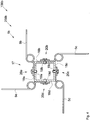
- FIG. 1 an exemplary first agricultural machine 100 is indicated or a pickup device 200 shown schematically and in perspective.
- a pickup roller 1 is disposed on a support frame 2 of the pickup device 200 so as to rotate in pivot bearings 3a and 3b about a horizontal axis HA.
- the pickup roller 1 comprises individual, lined up conveyor elements 4 with individual conveyor tines 5. These conveyor tines 5 form, for example, five rows of conveyor tines 5, of which in the present representation straight tine rows ZR 1 -ZR 3 are visible.
- the pickup roller 1 may further comprise stripping plates 6 and rotate - whether on eccentric cam tracks or not - the individual conveying elements 4 in a rotation R 1 .
- An at least one side of the pickup roller 1 provided rotary drive RA 1 is not shown in detail.
- a conveying aid FH is arranged in the form of a four-sided sheet-metal profile 9, likewise rotatable in a rotation R 2 which is opposite to the rotation R 1 , referred to below as counter-rotation R 2 .
- a rotary actuator RA 2 this one Counter-rotation R 2 generated is again not shown in detail.
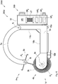
- the Fig. 2 shows the pickup device 200 from the Fig. 1 in a schematic and perspective view obliquely from behind.
- a skid 12 and support legs 13a and 13b can be seen.
- the latter are adjustable in height in support leg holders 14a and 14b and can be fixed by means of a securing pin.
- the support leg bracket 14b is concealed by a three-point mounting bracket DP which can pivot about a pendulum axis PA in a reciprocating motion PB by means of a pendulum tube suspension 16 in relation to the horizontal axis HA.
- the drive of the cross conveyor belt 10 - optionally the feed or stalks left or right depositing, ie counter or clockwise - accomplished by means of a toothed belt drive 15.
- This toothed belt drive 15 simultaneously represents a rotary drive RA 3 of the cross conveyor belt 10.
- FIG. 3 is a further pickup device 200a shown schematically and in perspective, which would result in an agricultural machine 100a together with a vehicle or tractor, not shown.
- the vast majority of components is from the previous ones FIGS. 1 and 2 already known and thus only with reference numbers with continuous index.
- this embodiment variant is a pickup roller 1a with helically arranged tine rows ZR 4 -ZR 7 . As shown approximately, the rotation of a tine row ZR 4 -ZR 7 can be about 90 degrees.
- a further agricultural machine 100b and a pickup device 200b may be characterized in that it comprises in addition to the known components a pickup roller 1b, which essentially comprises a square tube 17.
- This square tube in turn has four square sides 18a-18d, in each of which a threaded hole 19a-19d is mounted.
- a conveyor tine 5b-5e attached to each case by means of a screw fastening with Grover disc 20a-20d a conveyor tine 5b-5e attached.
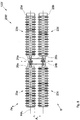
- a further agricultural machine 100c or a pickup device 200c and a pickup roller 1c may include a square tube 17a, which is twisted.
- a twist angle VW of approximately 90 degrees is achieved by an upper square side 18e side surface and a lateral square side 18f bottom.
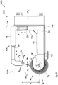
- the Fig. 6 shows a further agricultural machine 100d or pickup device 200d, which substantially the embodiment variant of the Fig. 3 corresponds and thus the already known there components are displayed only with continued indices.
- a 200d integrated hydraulic system 300 in the pickup apparatus for this purpose is a hydraulic oil reservoir HR provided within a housing 32 of a three-point trestle DP. 2
- an oil filter 21 and three hydraulic pumps HP 1 -HP 3 are integrated into the housing 32, preferably in each case a hydraulic pump for controlling a pickup roller 1d, a conveying aid FH 2 and a cross conveyor belt 10b.
- Fig. 7 1 shows an embodiment variant of an agricultural machine 100e according to the invention or a pickup device 200e according to the invention with an adjustment mechanism 400.
- a support frame 2c and a support arm 7f are each configured as hydraulic pistons 22a and 22b.
- a conveying aid FH 3 is height-adjustable relative to a pickup roller 1e along a vertical axis VA and adjustable along a direction of travel axis FRA such that the conveying aid FH 3 optionally in the direction of travel before, at the same level or behind the pickup roller 1e is arranged.
- the pickup apparatus 200e in a known manner a rotary bearing 3f, in which the pickup roll 1e in a rotation R 5 rotates.
- a sheet profile 9c rotates in opposite directions in a counter-rotation R. 6
- the Fig. 8 shows an agricultural machine 100f and pickup device 200f, which is characterized in that both a pickup roller 1f, as well as a similarly designed conveying aid FH 4 are divided into sub-rollers 23a-23d.
- the sub-rollers 23a and 23b of the conveying aid FH 4 and the sub-rollers 23c and 23c of the pickup roller 1f are respectively connected by a universal joint 24a and 24b.
- a respectively arranged on the sub-rollers 23b and 23d drive 25a and 25b thus also drives the sub-rollers 23a and 23c.
- the universal joints 24a and 24b ensure upward and downward movements depending on the shape of the ground.
- the two universal joints 24a and 24b are mounted telescopically displaceable at least on one side. Furthermore, in order to maintain a height clearance A 1 between the feed roll part rolls 23a-23d, the shafts of the universal joints 24a and 24b are connected to each other with rolling bearing bearings 26a and 26b.
- the pickup roller 1f may be a single, fixed roller, but the conveying aid has a hinge. This joint also allows up and down movements, for example, for receiving particularly thick feeder balls, but is limited by a limitation to a horizontal axis HA 1 .
- an agricultural machine with a pickup device can have individually controlled partial rollers, it would be possible to control the outer sub-roller at a higher rotational speed when describing curves, and thereby in turn the feed or stalk intake could be optimized in the curves ,
- an exemplary conveyor element or profile 4d is shown. It can therefore be a single element, but also a profile that extends over the entire width of the pickup device. It may also be provided for both the pickup, as well as for the conveyor rollers. This applies to all conveyor element or profile design variants 4d-4g shown below.
- the conveyor element or profile 4d forms four individual conveyor tines 5j-5m around an axis center 28a, which in turn each form an extension 27a-27d at their distal ends. These extensions 27a-27d are arranged counter to a rotation R 7 of the conveying element or profile 4d and are intended to prevent the feed or stalk material from getting caught at the ends.
- Fig. 9b shows a further embodiment variant of a conveying element or profile 4e, in which conveyor tines 5n-5q are each offset by an offset V 1 from a center axis 28b.
- Fig. 9c is a star-shaped conveying element or profile 4f shown schematically, in which a rotation Rg can take place either counterclockwise or clockwise.
- the Fig. 9d shows a windmill-like conveying element or profile 4g with against a rotational direction R 10 bent conveyor tines 5v-5y.
- FIG. 3 is a schematic plan view of how a working insert of an agricultural machine 100g may be configured with a tractor 29a.
- a front-mounted pickup device 200g may be pushed and two pickup devices 200h and 200i staggered with a double drawbar 30a may be pulled.
- a working width AB 1 is composed of an agricultural surface F1, which clears the pickup device 200g, advantageously, without the tractor 29a drüberement over feed or stalk material FG 1 and places it in a swath 31a, for example, in the direction FR 1 right from.
- An agricultural area F 2 with fodder FG 2 including the swath 31a, is picked up by the pickup device 200h recorded and stored in a swath 31b.
- the pickup device 200i which, without another swath, only needs to pick up feed or stalk material FG 3 from an agricultural surface F 3 and deposit it in a swath 31 c. This, in turn, would change as the pickup device 200g changes from right to left deposit by switching the rotation of its cross conveyor.
- the Fig. 10b shows an optional configuration of an agricultural 100h machine in which on a tractor 29b in a direction of travel FR 2 forward in front mounting a pickup device 200j and back again added disposed at a double pole 30b, two pickup devices are mounted 200k and 2001 respectively. In this configuration, the two rear pickup devices 200k and 2001 cooperate with each other and deposit a large swath 31e in the center.
Description
Die vorliegende Erfindung betrifft eine landwirtschaftliche Maschine zur Bearbeitung und Förderung von Erntegütern wie beispielsweise Gras, Luzerne, Klee, Futter, Silage, sonstiges Mähgut, Heu, Stroh usw. Ein treffender Oberbegriff hierfür ist Halmgut. Die landwirtschaftliche Maschine weist hierfür mindestens eine Pickup-Vorrichtung auf, d.h. eine Vorrichtung, die mindestens eine rotierende Walze mit daran angeordneten einzelnen Förderelementen oder -zinken für die Aufnahme des Erntegutes vom Boden aufweist.The present invention relates to an agricultural machine for processing and transporting crops such as grass, alfalfa, clover, fodder, silage, other crops, hay, straw, etc. Apt generic term for this is stalk crop. The agricultural machine has for this purpose at least one pickup device, i. a device having at least one rotating roller with arranged thereon individual conveying elements or tines for receiving the crop from the ground.
Bei der landwirtschaftlichen Maschine kann es sich hierbei beispielsweise generell um Schwader, vor allem eben um Pickup-Schwader oder um Bandschwader handeln oder aber auch um Heuwender, Schwadräumer, Ladewagen, Ballenpressen, Feldhäcksler usw.In the agricultural machine, this may, for example, generally swather, especially just pickup rake or band swather act or even hay tedders, windrowers, loader wagons, balers, forage harvesters, etc.
Primäres Ziel solcher Pickup-Vorrichtungen ist einerseits, das Erntegut möglichst schonend aufzunehmen. Die eiweißreichen Blätter sollen hierbei möglichst vollständig vom Boden mit aufgenommen werden und nicht nur die eiweißärmeren und schwerer verdaulichen Stiele. Andererseits soll weitestgehend vermieden werden, Erde und Steinchen mit aufzunehmen.The primary goal of such pickup devices is, on the one hand, to pick up the crop as gently as possible. The high-protein leaves should be taken up as completely as possible from the soil and not just the less protein-rich and less digestible stems. On the other hand, it should largely be avoided to include earth and stones.
Um die Aufnahme des Erntegutes hinsichtlich Aufnahme- und Ablagewinkel zu optimieren, sind sogenannte "gesteuerte" Pickup-Vorrichtungen entwickelt worden, bei denen die einzelnen Förderelemente oder -zinken auf einer exzentrischen Kurvenbahn geführt sind. Die Mechanik, welche diesen exzentrischen Kurvenbahnen zugrunde liegt, ist allerdings aufwändig, wartungsintensiv und teuer.In order to optimize the uptake of the crop with respect to receiving and storage angle, so-called "controlled" pickup devices have been developed in which the individual conveyor elements or tines are guided on an eccentric cam track. The mechanics underlying these eccentric cam tracks, however, is complex, maintenance-intensive and expensive.
Weitere, konzeptbedingte Nachteile der gesteuerten Pickup-Vorrichtungen sind relativ niedrige Arbeitsgeschwindigkeit und ein relativ ungleichmäßiger Futter-oder Halmgutfluss, der sich gerne mal verstopfen kann.Other conceptual disadvantages of the controlled pickup devices are relatively low operating speed and a relatively uneven feed or Halmgutfluss, who likes to clog.
Ungesteuerte Pickup-Vorrichtungen hingegen haben den Nachteil, dass sie vor allem kurzes, nasses Futter deutlich weniger sauber aufnehmen, d.h., der Verschmutzungsgrad des Futters mit Erde und Steinchen ist ziemlich hoch. Außerdem sind die ungesteuerten Pickup-Vorrichtungen auf hohe Drehzahlen und aggressive Zinkenstellung von harten Zinken angewiesen.Uncontrolled pickup devices, on the other hand, have the drawback that they absorb, in particular, short, wet feed much less cleanly, that is, the degree of contamination of the feed with earth and pebbles is quite high. In addition, the uncontrolled pickup devices rely on high speeds and aggressive tine position of hard tines.
Beide oder vielmehr alle bekannten Systeme funktionieren bergab bei gebotenen niedrigen Geschwindigkeiten nicht optimal, weil sie das Futter- bzw. Halmgut dann einfach nur noch aufnehmen und hochwerfen, aber nicht nach hinten über die Pickup-Walze hinweg auf das Querförderband bringen.Both or rather all known systems do not function optimally downhill at low speeds, because they then simply pick up and throw up the feed or stalk, but do not bring it to the rear over the pickup roller on the cross conveyor.
Die Offenlegungsschrift
Die Aufgabe der vorliegenden Erfindung ist, unter Vermeidung der oben aufgezeigten Nachteile eine neue landwirtschaftliche Maschine mit einer Pickup-Vorrichtung zu stellen, welche die Aufnahme und die Weitergabe, d.h. den sogenannten Futterfluss des Futter- bzw. Halmgutes nochmals verbessert und generell in ihren Eigenschaften und ihrer Anwendung optimiert ist.The object of the present invention, while avoiding the drawbacks set forth above, is to provide a new agricultural machine with a pickup device which permits the pick-up and transfer, i. The so-called feed flow of feed or Halmgutes improved again and is generally optimized in their properties and their application.
Die Lösung der Aufgabe besteht in der Bereitstellung einer landwirtschaftlichen Maschine gemäß Anspruch 1 und eines Verfahrens gemäß Anspruch 14.The object is to provide an agricultural machine according to claim 1 and a method according to claim 14.
Dabei besteht die Lösung der Aufgabe zunächst in der Anordnung von einer ersten rotierenden Pickup-Walze in bekannter Form und einer darüber ohne Bodenkontakt angeordneten, gegenläufig rotierenden Förderhilfe bzw. Gegenrechen bzw. Haspel. Diese Förderhilfe kann ebenfalls eine Walze mit einzelnen Förderelementen oder -zinken sein, aber auch ein einstückig durchgehendes Walzenprofil, auf dessen mögliche Ausgestaltungsformen im Folgenden noch eingegangen wird.Here, the solution of the problem initially in the arrangement of a first rotating pickup roller in a known form and arranged above it without ground contact, counter-rotating conveying aid or counter rake or reel. This conveyor may also be a roller with individual conveying elements or tines, but also an integrally continuous roller profile, whose possible embodiments will be discussed below.
Die zu der Pickup-Walze gegenläufige Rotationsrichtung der Förderhilfe bewirkt, im Unterschied zu dem passiven Weiterleiten des Futter- bzw. Halmgutes durch ein Niederhalter-Blech oder -Rollen, ein aktives Übernehmen, Weiterleiten und Ablegen des Futter- bzw. Halmgutes, vorzugsweise auf ein dahinter quer angeordnetes Förderband. Dieses Querförderband wiederum ist wahlweise im oder gegen den Uhrzeigersinn bedienbar und somit kann eine Ablage des Futter- bzw. Halmgutes wahlweise links oder rechts vom Fahrzeug oder Traktor erfolgen.The direction opposite to the pickup roller rotation direction of the conveying aid causes, in contrast to the Passive forwarding of the feed or crop by a hold-down sheet or rolls, an active takeover, forwarding and depositing the feed or crop, preferably on a behind transversely arranged conveyor belt. This cross conveyor in turn is either clockwise or counterclockwise operable and thus can be a storage of feed or Halmgutes either left or right of the vehicle or tractor.
Eine bevorzugte Ausgestaltungsvariante einer erfindungsgemäßen landwirtschaftlichen Maschine mit einer Pickup-Vorrichtung wird vorne oder hinten an dem Fahrzeug oder Traktor montiert, vorzugsweise mittels eines Dreipunkt-Anbaubockes, der jedoch nicht starr und fix mit dem Fahrzeug oder Traktor verbunden ist, sondern pendelnd. Hierfür ist zwischen der Vorderseite des Dreipunkt-Anbaubockes und einem Tragrahmen der Pickup-Vorrichtung ein zentrales Drehlager vorgesehen, das frei schwingen kann, sich Bodenquerneigungen anpassend. Optional kann diese Schwingbewegung um die Rotationsachse des zentralen Drehlagers federunterstützt sein.A preferred embodiment variant of an agricultural machine according to the invention with a pickup device is mounted on the front or rear of the vehicle or tractor, preferably by means of a three-point headstock, which is not rigidly and fixedly connected to the vehicle or tractor, but oscillating. For this purpose, a central pivot bearing is provided between the front of the three-point trestle and a support frame of the pickup device, which can swing freely, adapting to floor banks. Optionally, this oscillatory movement may be spring assisted about the axis of rotation of the central pivot bearing.
Der Antrieb der Pickup-Walze erfolgt bei einer erfindungsgemäßen landwirtschaftlichen Maschine mit einer Pickup-Vorrichtung vorzugsweise separat steuerbar, weiterhin vorzugsweise hydraulisch. Es sind jedoch auch mechanische oder elektrische Antriebe gut realisierbar. Der Antrieb der erfindungsgemäßen Förderhilfe kann an den Antrieb der Pickup-Walze gekoppelt sein, beispielsweise mittels einer Zahn- oder Keilriemen- oder Zahnradgetriebe-Anordnung. Es ist jedoch bevorzugt, ebenfalls vorzugsweise hydraulisch, auch den Antrieb und die Rotationsgeschwindigkeit der Förderhilfe separat ansteuerbar auszugestalten.The drive of the pickup roller is preferably separately controllable in an agricultural machine according to the invention with a pickup device, further preferably hydraulically. However, mechanical or electrical drives are also well feasible. The drive of the conveying aid according to the invention may be coupled to the drive of the pickup roller, for example by means of a toothed or V-belt or gear transmission arrangement. However, it is also preferable, preferably also hydraulically, to configure the drive and the rotational speed of the conveying aid separately.
Eine erfindungsgemäße landwirtschaftlichen Maschine mit einer Pickup-Vorrichtung umfasst einen Verstell-Mechanismus der Förderhilfe, mit Hilfe dessen die relative Höhe der Förderhilfe zu der Pickup-Walze adaptierbar ist, vorzugsweise fernbedient vom Fahrzeug oder Traktor aus, während des laufenden Arbeitens. Des Weiteren umfasst dieser Verstell-Mechanismus auch eine Verstellmöglichkeit der Förderhilfe in der Horizontalen, d.h. ein wahlweises Platzieren der Rotationsachse der Förderhilfe vor, annähernd gleich weit oder hinter die Rotationsachse der Pickup-Walze. Es bietet sich an, diesen Verstell-Mechanismus mittels Hydraulik-Kolben zu realisieren.An agricultural machine according to the invention with a pickup device comprises an adjustment mechanism of the conveying aid, by means of which the relative height of the conveying aid to the pickup roll is adaptable, preferably remotely controlled by the vehicle or tractor, while the work is in progress. Furthermore, this adjustment mechanism also includes an adjustment of the conveying aid in the horizontal, ie an optional placement of the axis of rotation of the conveyor before, approximately equal to or behind the axis of rotation of the pickup roller. It makes sense to realize this adjustment mechanism by means of hydraulic pistons.
Es ist möglich, die Pickup-Walze in einer einzigen Walze auszugestalten, zugunsten einer verbesserten Anpassbarkeit an welliges Gelände kann es jedoch vorgesehen sein, die Pickup-Walze aus mehreren Teilwalzen bestehen zu lassen.It is possible to design the pickup roller in a single roller, but for improved adaptability to undulating terrain, it may be provided to make the pickup roller consist of several sub-rollers.
Bei zwei Teilwalzen kann an jeder Außenseite einer Teilwalze ein Antrieb vorgesehen sein. In diesem Falle genügt ein Verbindungsgelenk zwischen den Teilwalzen, welches lediglich in der Lage ist, eine Vertikalbewegung dieses Verbindungsgelenkes entlang einer Vertikalachse bzw. eine Verschränkung der beiden Teilwalzen zuzulassen. Sofern hingegen ein einziger Antrieb für beide Teilwalzen vorgesehen ist oder sofern mehr als zwei Teilwalzen angeordnet sind, so sind Kardangelenke als Verbindungsgelenke erforderlich, mindestens einseitig teleskopisch axial verschiebbar gelagert.With two sub-rollers, a drive can be provided on each outer side of a sub-roller. In this case, a connecting joint between the sub-rollers, which is only able to allow a vertical movement of this connecting joint along a vertical axis or an entanglement of the two sub-rollers is sufficient. If, however, a single drive for both sub-rollers is provided or if more than two sub-rollers are arranged, then cardan joints are required as connecting joints, mounted on at least one side telescopically axially displaceable.
Die Förderhilfe kann ebenfalls in einer einzigen Walze, oder aber auch in mehreren Teilwalzen realisiert sein. Bei der Anordnung einer einzigen, starren Pickup-Walze empfiehlt sich die Ausgestaltung der Förderhilfe in mehreren Teilwalzen, verbunden mit einem oder mehreren Gelenken, insofern, als dass ein Blockieren oder Verstopfen der Pickup-Vorrichtung bei großen Halmgut-Knäueln vermieden wird. Die Gelenke sind in diesem Fall vorzugsweise mit einem Wegbegrenzer so limitiert, dass sie gegen den Druck eines solchen Halmgut-Knäuels zwar eine Öffnungsbewegung der Förderhilfen-Teilwalzen nach oben erlauben, aber wenn wieder ohne Druck, wieder parallel zu der Pickup-Walze ausgerichtet sind.The conveying aid can also be realized in a single roller, or else in several sub-rollers. In the arrangement of a single, rigid pickup roller, the design of the conveying aid in a plurality of sub-rollers, connected to one or more joints, is recommended in that blocking or clogging of the pick-up device is avoided in the case of large stalk stuffs. The joints are limited in this case preferably with a Wegbegrenzer so that they allow against the pressure of such Halmgut-ball while an opening movement of the conveyor sub-rollers upwards, but when again without pressure, are aligned again parallel to the pickup roller.
Im Falle der Anordnung einer Pickup-Walze, die aus mehreren und mit Gelenken miteinander verbundenen Teilwalzen besteht, so ist es bei einer entsprechenden Ausgestaltungsvariante einer erfindungsgemäßen landwirtschaftlichen Maschine mit einer Pickup-Vorrichtung vorgesehen, die Förderhilfe symmetrisch mit Teilwalzen und sie verbindenden Gelenken auszugestalten und die Gelenkanordnungen der Pickup-Teilwalzen mit denjenigen der Förderhilfen-Teilwalzen zu koppeln. Auf diese Weise ist eine landwirtschaftliche Maschine mit einer an das Bodengelände adaptierbaren Pickup-Vorrichtung realisiert, und Förderhilfen-Teilwalzen behalten ihren optimalen Abstand zu den Pickup-Teilwalzen immer bei.In the case of the arrangement of a pickup roller, which consists of several and interconnected with joints sub-rollers, it is provided in a corresponding embodiment variant of an agricultural machine according to the invention with a pickup device to design the conveying aid symmetrical with sub-rollers and joints connecting them and the Joint arrangements of the pickup sub-rollers with those of the conveyor sub-rollers to couple. In this way, an agricultural machine is realized with a pickup device that can be adapted to the ground, and conveyor sub-rollers always maintain their optimum distance from the pickup sub-rollers.
Eine erfindungsgemäße Pickup-Vorrichtung umfasst des Weiteren ein rückseitiges Leitblech, welches das Halmgut auf das quer angeordnete Förderband leitet. Darüber hinaus kann die Pickup-Vorrichtung eine Abdeckung aufweisen, die vorzugsweise halbrund ausgestaltet ist.A pickup device according to the invention further comprises a rear baffle which directs the stalk crop on the transversely arranged conveyor belt. In addition, the pickup device may have a cover, which is preferably designed semicircular.
Die Abdeckung kann beispielsweise auf ebenfalls halbrund ausgestalteten Tragarmen lose aufgelegt sein. Mindestens zwei Tragarme sind auf jeden Fall Bestandteil des Tragrahmens einer erfindungsgemäßen Pickup-Vorrichtung und tragen die mindestens eine Förderhilfen-Walze und den oder die Antriebe der Förderhilfe. Die Tragarme sind vorzugsweise an dem Tragrahmen mittels pendelnder Gelenke angeordnet und weiterhin kann auch die mindestens eine Förderhilfen-Walze ebenfalls in solchen pendelnden Gelenken gelagert sein.The cover can be placed loosely, for example, on likewise semi-circular support arms. At least two support arms are in any case part of the support frame of a pickup device according to the invention and carry the at least one conveying aid roller and the one or more drives of the conveying aid. The support arms are preferably arranged on the support frame by means of pendulum joints and furthermore, the at least one conveying aid roller can also be mounted in such pendulum joints.
Eine erfindungsgemäße landwirtschaftliche Maschine mit einer Pickup-Vorrichtung oder besser gesagt eine erfindungsgemäße Pickup-Vorrichtung ist vorzugsweise mit mindestens zwei Gleitkufen an ihrer Unterseite ausgestattet. Selbstverständlich kommen auch Rollen in Betracht. Sowohl Gleitkufen, als auch Rollen können optional mit Stoßdämpfern angeordnet sein.An agricultural machine according to the invention with a pickup device or, better said, a pickup device according to the invention is preferably equipped with at least two skids on its underside. Of course, roles come into consideration. Both skids and rollers can optionally be equipped with shock absorbers be arranged.
Wie in Absatz [0010] bereits erwähnt, kann eine erfindungsgemäße Förderhilfe eine Walze mit einzelnen Förderelementen oder -zinken sein, aber auch ein einstückig durchgehendes Walzenprofil. Zunächst kommt also eine klassische Form in Betracht, analog zu der Pickup-Walze, mit einzelnen Förderelementen in Form von Förderzinken, die optional zwischen Abstreif-Blechen angeordnet sein können. Als weitere einzelne Förderelemente kommen im Querschnitt hakenkreuz-, stern-, windrad- oder bürstenförmige Ausformungen in Betracht. All diese Formen können als einzelne Förderelemente ausgeprägt sein, aber auch als wenige, entsprechend breit ausgestaltete Förderelemente oder gar als ein einziges, einstückiges Förderelement, das sich über die gesamte Breite der Förderhilfen-Walze erstreckt. Als eine günstige und sehr gut funktionierende Ausgestaltungsvariante hat sich ein durchgehendes Blechprofil mit vier Flügeln erwiesen. Dieses Blechprofil kann optional auch Perforationen oder Ausstanzungen oder eine glattflächige Gitterstruktur aufweisen, funktioniert aber möglicherweise deshalb besonders gut, weil die Flügel fächer- oder propellerartig einen Sog und Luftstoß erzeugen, der wiederum den Futter- bzw. Gutfluss optimiert.As already mentioned in paragraph [0010], a conveying aid according to the invention may be a roller with individual conveying elements or tines, but also an integrally continuous roller profile. First of all, therefore, a classic shape is considered, analogous to the pickup roller, with individual conveying elements in the form of conveying tines, which can optionally be arranged between stripper plates. As further individual conveying elements come in cross-section swastika, star, wind-wheel or brush-shaped formations into consideration. All of these shapes may be pronounced as individual conveying elements, but also as a few, correspondingly broadly designed conveying elements or even as a single, one-piece conveying element which extends over the entire width of the conveying aid roller. As a cheap and very well-working design variant, a continuous sheet profile with four wings has been found. This sheet metal profile may optionally also have perforations or punches or a smooth-surfaced lattice structure, but may work particularly well because the vanes fan-like or propeller-like produce a suction and air blast which in turn optimizes the feed flow.
Die einzelnen Förderelemente bzw. deren Förderzinken oder -flügel können optional geriffelt sein oder umgekehrt reibungsmindernd glattgeschliffen oder poliert sein, oder aber auch haftungsverbessernd oberflächenbeschichtet oder generell beschichtet oder gummiert sein.The individual conveying elements or their conveying tines or wings can optionally be corrugated or, conversely, friction-reduced smooth ground or polished, or else surface-coated to improve adhesion or generally coated or gummed.
Als Materialien, die für die Fertigung der einzelnen Förderelemente in Betracht kommen, sei vor allem rostfreier Stahl oder vielmehr Federstahl erwähnt, aber es kommen auch Kunststoffe, textilverstärkter Kautschuk, Leder, GFK und Carbon in Frage.As materials that come into consideration for the production of the individual conveying elements, especially stainless steel or spring steel is mentioned, but there are also plastics, textile-reinforced rubber, leather, fiberglass and carbon in question.
Eine erfindungsgemäße landwirtschaftliche Maschine oder besser gesagt eine erfindungsgemäße Pickup-Vorrichtung kann grundsätzlich mit einer mechanischen Steuerung eine exzenterförmige Bewegung der einzelnen Förderzinken aufweisen, kommt aber ganz gut mit einem zentral angeordneten und angetriebenen Rohr oder Vierkant-Rohr aus, an dem die einzelnen Förderzinken oder -flügel zentrisch oder aber auch dezentrisch versetzt angeordnet sein können.An agricultural machine according to the invention or rather a pickup device according to the invention can in principle have a mechanical control of an eccentric movement of the individual conveyor tines, but comes off quite well with a centrally arranged and driven pipe or square tube on which the individual conveyor tines or - Wing can be arranged centrally or offset but also offset.
In einer einfachen und bevorzugten Ausgestaltungsvariante umfasst die Förderhilfe ein Vierkant-Rohr, an dessen vier Seiten Gewindelöcher für die Montage von vier Förderelement-Reihen vorgesehen sind.In a simple and preferred embodiment variant, the conveying aid comprises a square tube, on the four sides of which threaded holes are provided for the assembly of four conveyor element rows.
Es wurde allerdings beobachtet, dass eine Anordnung der Förderzinken in Reihen, üblicherweise sind dieses vier, fünf oder sechs Reihen, nicht immer wirklich optimal für die Erzeugung eines schön fließenden Futter- oder Gutflusses ist. Durch das Eingreifen am Boden aller Zinken einer Reihe auf einmal, gefolgt durch eine Pause bis zum erneuten Eingreifen der nächsten Reihe, ist der Kraftaufwand ungleichmäßig bzw. der Kraftfluss zerstückelt.However, it has been observed that placing the conveyor tines in rows, usually four, five, or six rows, is not always optimal for producing a well-flowing feed or crop flow. Intervening at the bottom of all the tines in a row at once, followed by a pause until the next row intervenes again, the effort is uneven or the power flow is fragmented.
Es ist somit eine weitere gestellte Aufgabe der vorliegenden Patentanmeldung, den Kraft- und Futterfluss gleichmäßiger auszugestalten.It is thus a further object of the present patent application to design the force and feed flow more uniformly.
Die Lösung zu dieser Aufgabe ist die Anordnung eines Antriebsstranges bzw. einer oder mehrerer Pickup-Walzen mit Hilfe eines Vierkant-Rohres, welches verdreht ist. Der Verdrehungswinkel liegt in einem Bereich von 10 bis 180 Grad und beträgt vorzugsweise 90 Grad. Weiterhin vorzugsweise sind an jeder Vierkant-Seite des verdrehten Vierkant-Rohres mittels Gewindebohrungen die einzelnen Förderelemente angeordnet und bilden somit vier sich helikoidal erstreckende Förderzinken-Reihen. Oder es werden Doppelzinken montiert, die zwei helikoidale Zinkenreihen ergeben, die sich gegenüberliegen. Auf diese Weise erfolgt immer ein Bodenkontakt bzw. eine Aufnahmebewegung mehrerer Förderzinken auf einmal und dieses bleibt kontinuierlich so. Die Aufnahme erfolgt nicht mehr stoßweise.The solution to this problem is the arrangement of a drive train or one or more pickup rollers by means of a square tube, which is twisted. The twist angle is in a range of 10 to 180 degrees, and is preferably 90 degrees. Further preferably, the individual conveyor elements are arranged on each square side of the twisted square tube by means of threaded holes and thus form four helically extending conveyor tine rows. Or double tines are mounted, the two result in helical rows of tines that face each other. In this way, there is always a ground contact or a picking movement of several tines at a time and this remains so continuously. The recording is no longer intermittent.
Analoge Anordnungen sind gut auch mit einem Sechskant-Rohr realisierbar. An so einem Sechskant-Rohr oder aber auch an einer klassisch ausgestalteten, runden Hauptwelle können die Förderelemente oder -zinken randomisiert oder in Blöcken angeordnet sein.Analog arrangements are well feasible with a hexagonal tube. On such a hexagonal tube or even on a classically designed, round main shaft, the conveying elements or tines can be randomized or arranged in blocks.
Nicht nur die Pickup-Walze oder -Walzen können durch eine solche helikoidale Anordnung der Förderelemente gekennzeichnet sein, sondern auch die Förderhilfen-Walze oder - Walzen. Hieraus ergibt sich die Möglichkeit, die Pickup-Walzen und die Förderhilfen-Walzen bezüglich Anordnung und Rotationsgeschwindigkeit so aufeinander abzustimmen, dass immer eine schlangenförmige Zinkenreihe einer Förderhilfen-Walze in einen Zwischenraum zwischen zwei kongruent schlangenförmigen Zinkenreihen einer Pickup-Walze eingreift. Die Möglichkeit dieser ineinander eingreifenden Anordnung der Zinkenreihen besteht natürlich auch bei den eingangs beschriebenen geraden Zinkenreihen.Not only the pickup roller or rollers may be characterized by such a helical arrangement of the conveyor elements but also the conveyor roller or rollers. This results in the possibility of the pickup rollers and the conveyor rollers with respect to arrangement and rotational speed coordinated so that always engages a serpentine tine row of a conveyor roller in a space between two congruent serpentine tine rows of a pickup roller. The possibility of this interlocking arrangement of tine rows is of course also in the straight rows of tines described above.
Wie bereits erwähnt, kann der Antrieb einer erfindungsgemäßen Pickup-Vorrichtung mechanisch oder elektrisch erfolgen, es ist aber bevorzugt, einen hydraulischen Antrieb zu realisieren. Sofern das Fahrzeug bzw. der Traktor mit einer hinreichend steuerbaren Hydraulik-Anlage mit genügend einzeln ansteuerbaren Einzel-Anschlüssen ausgerüstet ist, so kann idealerweise ein Einzel-Anschluss für die Steuerung der Pickup-Walze, ein zweiter für die Steuerung der Förderhilfe und ein dritter für die Steuerung des quer angeordneten Förderbandes verwendet werden. In denjenigen Fällen hingegen, in denen die Hydraulik-Anlage des Fahrzeugs oder Traktors nicht genügend Einzel-Anschlüsse aufweist, wäre eine erfindungsgemäße Pickup-Vorrichtung nicht mehr einzeln und optimal ansteuerbar.As already mentioned, the drive of a pickup device according to the invention can take place mechanically or electrically, but it is preferred to implement a hydraulic drive. If the vehicle or the tractor is equipped with a sufficiently controllable hydraulic system with sufficient individually controllable individual connections, so ideally a single connection for the control of the pickup roller, a second for the control of the pickup and a third for the control of the transverse conveyor belt can be used. In those cases, however, where the hydraulic system of the vehicle or tractor is insufficient Single connections, a pickup device according to the invention would not be individually and optimally controlled.
Die Lösung dieser weiteren, dritten Aufgabe besteht in der weiterhin erfindungsgemäßen Integration des oder der Reservoire für das Hydrauliköl, sowie von Ölpumpenmotoren, Ölfiltern, Anschlüssen, Ventilen und Steuerung in den Dreipunkt-Anbaubock bzw. in sein Gehäuse. Eine erfindungsgemäße Pickup-Vorrichtung ist somit autark und benötigt lediglich einen Hauptantrieb, der von dem Fahrzeug bzw. Traktor abgegriffen wird. Dieser Hauptantrieb für die Ölpumpenmotoren oder einen zentralen Ölpumpenmotor der Pickup-Vorrichtung kann erstrecht wieder hydraulisch sein, aber auch elektrisch oder mechanisch, indem das erforderliche Gesamt-Antriebsdrehmoment von der Haupt-Zapfwelle des Fahrzeugs oder Traktors abgegriffen wird.The solution of this further, third object is in the further integration according to the invention of the reservoir or reservoirs for the hydraulic oil, as well as oil pump motors, oil filters, connections, valves and control in the three-point headstock or in his housing. A pickup device according to the invention is thus self-sufficient and only requires a main drive, which is tapped by the vehicle or tractor. This main drive for the oil pump motors or a central oil pump motor of the pickup device can firstly be hydraulic again, but also electrically or mechanically, by the required total drive torque is tapped from the main PTO of the vehicle or tractor.
Optional können die beschriebenen drei autarken Einzelsteuerungen der Pickup-Vorrichtung mit Fernbedienungen oder einem Fernbedienungs-Pult von der Fahrerkabine aus bedient werden.Optionally, the described three autonomous individual controls of the pickup device with remote controls or a remote control console can be operated from the driver's cab.
Die offenbarten unterschiedlichen Ausgestaltungsvarianten einer erfindungsgemäßen landwirtschaftlichen Maschine mit einer Pickup-Vorrichtung sind hinsichtlich der nicht grundfunktionsrelevanten Merkmale beliebig miteinander kombinierbar. So sind beispielsweise alle beschriebenen Ausgestaltungsvarianten mit den beschriebenen Förderelementen oder -profilen oder mit dem beschriebenen Querförderband oder mit der pendelnden Aufhängung des Dreipunkt-Anbaubockes kombinierbar. Dieses ungeachtet eines mechanischen, elektrischen oder hydraulischen Antriebs oder einer Kombination hiervon und auch ungeachtet dessen, ob der Antrieb der Förderhilfe an den Antrieb der Pickup-Walze gekoppelt ist oder nicht. Auch der beschriebene Verstell-Mechanismus ist mit allen Ausgestaltungsvarianten kombinierbar, genauso wie die Ausgestaltungsvarianten mit Teilwalzen, sei es für die Pickup-Walze oder für die Förderhilfe oder für beides. Die gleiche reziproke Kombinierbarkeit gilt für alle Ausgestaltungsvarianten untereinander, egal, ob sie gerade oder helikoidale Zinkenreihen haben oder ob eine Hydraulik-Anlage integriert ist oder nicht.The disclosed different design variants of an agricultural machine according to the invention with a pickup device can be combined with each other in terms of non-basic function-relevant features. Thus, for example, all described design variants can be combined with the described conveying elements or profiles or with the described transverse conveyor belt or with the swinging suspension of the three-point attachment head. This regardless of a mechanical, electrical or hydraulic drive or a combination thereof and regardless of whether the drive of the conveying aid is coupled to the drive of the pickup roller or not. Also, the adjustment mechanism described can be combined with all design variants, as well as the design variants with part rollers, be it for the pickup roller or for the grant or for both. The same reciprocal combinability applies to all design variants with each other, regardless of whether they have straight or helical tine rows or whether a hydraulic system is integrated or not.
Die vorliegende Anmeldung offenbart ein Verfahren zur Schwadformung und -ablage von Futter- bzw. Halmgut mit einer landwirtschaftlichen Maschine mit einer Fahrtrichtung und einer Fahrtrichtungs-Achse und mit mindestens einer Pickup-Vorrichtung, mit folgenden grundsätzlichen Verfahrensschritten:
- a)- Betätigen eines ersten Rotationsantriebs einer Pickup-Walze;
- b)- Betätigen eines zweiten, gegenläufigen Rotationantriebs einer Förderhilfe;
- c)- Betätigen eines dritten Rotationsantriebs eines quer angeordneten Förderbandes;
- d)- falls erforderlich, Einstellen und Adaptieren der Rotationsgeschwindigkeiten der drei Rotationsantriebe zueinander;
- e)- falls erforderlich, Einstellen eines vertikalen Höhenabstandes und eines horizontalen Versatzes der Rotationsachse der Förderhilfe entlang der Fahrtrichtungs-Achse vor, gleich weit oder hinter die Rotationsachse der Pickup-Walze;
- f)- In-Fahrt-Setzen der landwirtschaftlichen Maschine auf einer landwirtschaftlichen Fläche mit darauf liegendem Futter- bzw. Halmgut;
- g)- falls erforderlich, Einstellen und Adaptieren der Rotationsgeschwindigkeiten der drei Rotationsantriebe während der Fahrt;
- h)- falls erforderlich, Einstellen und Adaptieren des vertikalen Höhenabstandes und des horizontalen Versatzes der Rotationsachse der Förderhilfe entlang der Fahrtrichtungs-Achse vor, gleich weit oder hinter die Rotationsachse der Pickup-Walze.
- a) - actuating a first rotary drive of a pickup roller;
- b) - actuating a second, counter-rotating drive of a funding aid;
- c) - actuating a third rotary drive of a transversely arranged conveyor belt;
- d) - if necessary, setting and adapting the rotational speeds of the three rotary drives to each other;
- e) - if necessary, setting a vertical vertical distance and a horizontal offset of the axis of rotation of the conveying aid along the direction of travel axis, equidistant or behind the axis of rotation of the pickup roller;
- f) - driving the agricultural machine into an agricultural area with feed or stalks lying thereon;
- g) - if necessary, adjusting and adapting the rotational speeds of the three rotary drives while driving;
- h) - if necessary, setting and adapting the vertical vertical distance and the horizontal offset of the axis of rotation of the conveying aid along the direction of travel axis, equidistant or behind the axis of rotation of the pickup roller.
Eine erfindungsgemäße landwirtschaftliche Maschine mit einer Pickup-Vorrichtung bringt folgende Vorteile:
- Das Futter- bzw. Halmgut wird schonend aufgenommen und schonend weiterverarbeitet.
- Das Futter- bzw. Halmgut ist qualitativ hochwertig, weil die eiweißreichen Blätter dran bleiben.
- Das Futter- bzw. Halmgut weist einen niedrigen Verschmutzungsgrad auf.
- Eine erfindungsgemäße Pickup-Vorrichtung kommt ohne teure Exzenterführungen aus.
- Es sind hohe Arbeitsgeschwindigkeiten möglich.
- Es findet ein gleichmäßiger Futterfluss ohne Überwerfen statt.
- Die Maschine verstopft sich nicht so leicht.
- Sie ist ideal für das Wenden von Stroh und das Schwaden von beliebigen Futterarten.
- Obwohl sie ungesteuert ist, kommt sie ohne aggressive Zinkenstellung und harte Zinken aus.
- Sie funktioniert auch bergab, das Futter rollt nicht nach vorne.
- Es werden lockere Schwaden erzeugt, die gut nachtrocknen können.
- Das Futter wird auch bei schneller Fahrt nicht aufgewirbelt.
- Die Ablage der Schwade kann wahlweise links oder rechts erfolgen.
- Falls eine separate Steuerung für die Förderhilfe vorgesehen ist, findet ein steuerbares und aktives Weiterleiten des Futters statt.
- Eine erfindungsgemäße Pickup-Vorrichtung ist sowohl vorne, als auch hinten an einem Fahrzeug oder Traktor montierbar.
- Bei Frontanbau gelangt kein Staub durch den Traktor in das Futter.
- Der Traktor fährt nicht über das Futter drüber.
- Die pendelnde Aufhängung des Dreipunkt-Anbaubockes garantiert eine gute Anpassung an Bodenquerneigungen.
- Die Position der Förderhilfe zu der Pickup-Walze ist in zwei Achsen verstellbar, falls vorgesehen, mit einer Fernbedienung aus der Fahrerkabine heraus.
- Falls die Pickup-Walze in mehrere Teilwalzen aufgeteilt ist, gewährleistet die landwirtschaftliche Maschine eine gute Geländeanpassung.
- Mit einem Vierkant-Rohr ist eine gute und günstige Hauptwelle realisiert.
- Falls die helikoidale Zinkenanordnung vorgesehen ist, findet ein gleichmäßiger und homogener Kraftaufwand statt.
- Falls vorgesehen, ist eine erfindungsgemäße landwirtschaftliche Maschine mit einer weiterhin erfindungsgemäßen Pickup-Vorrichtung von der Hydraulik-Anlage des Traktors unabhängig.
- Die erfindungsgemäße Pickup-Vorrichtung zeichnet sich durch hohe Lebensdauer und geringen Wartungsaufwand aus.
- The feed or stalk material is gently absorbed and processed gently.
- The feed or stalk crop is of high quality, because the protein-rich leaves stay tuned.
- The feed or stalk crop has a low degree of contamination.
- A pickup device according to the invention does not require expensive eccentric guides.
- High working speeds are possible.
- There is a uniform feed flow without knocking over.
- The machine does not clog up so easily.
- It is ideal for turning straw and swathing of any type of feed.
- Although she is uncontrolled, she gets along without aggressive tine position and hard prongs.
- It also works downhill, the feed does not roll forward.
- It creates loose swaths that can dry well.
- The food is not whirled up even when driving fast.
- The filing of the swath can either be left or right.
- If a separate control is provided for the funding, there is a controllable and active forwarding of the feed.
- A pickup device according to the invention can be mounted both at the front and at the rear on a vehicle or tractor.
- With front attachment no dust gets through the tractor into the feed.
- The tractor does not drive over the food over it.
- The pendulum suspension of the three-point headstock guarantees a good adaptation to ground banks.
- The position of the conveying aid to the pickup roller is adjustable in two axes, if provided, with a remote control from the driver's cab.
- If the pickup roller is divided into several sub-rollers, the agricultural machine ensures a good terrain adjustment.
- With a square tube, a good and cheap main shaft is realized.
- If the helical tine assembly is provided, there will be a more even and homogeneous effort.
- If provided, an agricultural machine according to the invention with a further inventive pickup device of the hydraulic system of the tractor is independent.
- The pickup device according to the invention is characterized by a long service life and low maintenance.
Weitere oder vorteilhafte Ausgestaltungen einer erfindungsgemäßen landwirtschaftlichen Maschine mit einer Pickup-Vorrichtung bilden die Gegenstände der abhängigen Ansprüche.Further or advantageous embodiments of an agricultural machine according to the invention with a pickup device form the subject of the dependent claims.
Die Bezugszeichenliste ist Bestandteil der Offenbarung.The list of reference numerals is part of the disclosure.
Anhand von Figuren wird die Erfindung symbolisch und beispielhaft näher erläutert. Die Figuren werden zusammenhängend und übergreifend beschrieben. Sie stellen schematische und beispielhafte Darstellungen dar und sind nicht maßstabsgetreu, auch in der Relation der einzelnen Bestandteile zueinander nicht. Gleiche Bezugszeichen bedeuten das gleiche Bauteil, Bezugszeichen mit unterschiedlichen Indizes geben funktionsgleiche oder ähnliche Bauteile an.The invention will be explained symbolically and by way of example with reference to figures. The figures are described coherently and comprehensively. They represent schematic and exemplary representations and are not to scale, not even in the relation of the individual components to each other. Identical reference symbols denote the same component, reference symbols with different indices indicate functionally identical or similar components.
Es zeigen dabei
-
Fig. 1 eine schematische und perspektivische Darstellung einer beispielhaften landwirtschaftlichen Maschine mit einer Pickup-Vorrichtung bzw. einer Pickup-Vorrichtung mit einer Förderhilfe; -
Fig. 2 eine schematische und perspektivische Rückansicht der landwirtschaftlichen Maschine mit einer Pickup-Vorrichtung bzw. der Pickup-Vorrichtung mit einer Förderhilfe aus derFig. 1 ; -
Fig. 3 eine schematische und perspektivische Darstellung einer zweiten beispielhaften landwirtschaftlichen Maschine mit einer Pickup-Vorrichtung bzw. einer Pickup-Vorrichtung mit einer Förderhilfe; -
Fig. 4 eine schematische Darstellung eines beispielhaften Förderhilfen-Antriebs mittels eines Vierkant-Rohres als Sitz für Förderelemente; -
Fig. 5 eine schematische und perspektivische Darstellung eines verdrehten Vierkant-Rohres als Sitz für die Förderelemente bzw. -zinken; -
Fig. 6 eine schematische Seitenansicht der zweiten beispielhaften landwirtschaftlichen Maschine mit einer Pickup-Vorrichtung bzw. der Pickup-Vorrichtung mit einer Förderhilfe aus derFig. 3 ; -
Fig. 7 eine schematische Seitenansicht einer Ausgestaltungsvariante einer erfindungsgemäßen landwirtschaftlichen Maschine mit einer Pickup-Vorrichtung, bei der eine Förderhilfe entlang einer Vertikal- sowie einer Horizontal-Achse verstellbar ist; -
Fig. 8 eine schematische Darstellung einer landwirtschaftlichen Maschine mit einer Pickup-Vorrichtung, bei der sowohl die Pickup-Walze, als auch die Förderhilfen-Walze in mehrere Teilwalzen aufgeteilt ist und diese Teilwalzen mit Gelenken verbunden sind; -
Fig. 9a eine schematische Seitenansicht einer ersten Ausgestaltungsvariante eines Förderelements oder -profils; -
Fig. 9b eine schematische Seitenansicht einer zweiten Ausgestaltungsvariante eines Förderelements oder -profils; -
Fig. 9c eine schematische Seitenansicht einer dritten Ausgestaltungsvariante eines Förderelements oder -profils; -
Fig. 9d eine schematische Seitenansicht einer vierten Ausgestaltungsvariante eines Förderelements oder -profils; -
Fig. 10a eine schematische Draufsicht auf einen Traktor bei einem Arbeitseinsatz mit drei erfindungsgemäßen Pickup-Vorrichtungen und -
Fig. 10b eine schematische Draufsicht auf einen Traktor bei einem Arbeitseinsatz mit ebenfalls drei erfindungsgemäßen Pickup-Vorrichtungen, aber in einer leicht abgeänderten Anordnung.
-
Fig. 1 a schematic and perspective view of an exemplary agricultural machine with a pickup device or a pickup device with a conveying aid; -
Fig. 2 a schematic and perspective rear view of the agricultural machine with a pickup device or the pickup device with a support from theFig. 1 ; -
Fig. 3 a schematic and perspective view of a second exemplary agricultural machine with a pickup device or a pickup device with a conveying aid; -
Fig. 4 a schematic representation of an exemplary conveyor aids drive by means of a square tube as a seat for conveying elements; -
Fig. 5 a schematic and perspective view of a twisted square tube as a seat for the conveying elements or tines; -
Fig. 6 a schematic side view of the second exemplary agricultural machine with a pickup device or the pickup device with a conveying aid from theFig. 3 ; -
Fig. 7 a schematic side view of an embodiment variant of an agricultural machine according to the invention with a pickup device, in which a conveying aid along a vertical and a horizontal axis is adjustable; -
Fig. 8 a schematic representation of an agricultural machine with a pickup device, in which both the pickup roller, and the conveying aid roller is divided into several sub-rollers and these sub-rollers are connected by joints; -
Fig. 9a a schematic side view of a first embodiment variant of a conveying element or profile; -
Fig. 9b a schematic side view of a second embodiment variant of a conveying element or profile; -
Fig. 9c a schematic side view of a third embodiment variant of a conveying element or profile; -
Fig. 9d a schematic side view of a fourth Embodiment variant of a conveying element or profile; -
Fig. 10a a schematic plan view of a tractor in a work application with three pickup devices according to the invention and -
Fig. 10b a schematic plan view of a tractor in a work with also three pickup devices according to the invention, but in a slightly different arrangement.
In der
An dem Tragrahmen 2 sind des Weiteren zwei annähernd halbrunde Tragarme 7a und 7b angeordnet, vorzugsweise in Pendelgelenken oder sogenannten Kugelaugen-Kupplungen 8a und 8b. Vorzugsweise ebenfalls in solchen Kugelaugen-Kupplungen 8c und 8d ist eine erfindungsgemäße Förderhilfe FH in Form eines vierflächigen Blechprofils 9 angeordnet, ebenfalls drehbar in einer zu der Rotation R1 gegenläufigen Rotation R2, im Folgenden Gegenrotation R2 genannt. Ein Rotationsantrieb RA2, der diese Gegenrotation R2 erzeugt, ist erneut nicht näher dargestellt.Furthermore, two approximately
Durch diese Anordnung ist gewährleistet, dass Futter- bzw. Halmgut von den Förderzinken 5 der Pickup-Walze 1 vom Boden aufgenommen, hochgehoben, anschließend von der Förderhilfe FH bzw. dem Blechprofil 9 übernommen und weitergeleitet wird und auf ein Querförderband 10 abgelegt wird. Ein Leitblech 11 leitet über die Breite des Querförderbandes 10 hinausschießendes Futter- bzw. Halmgut wieder auf das Querförderband 10 zurück.By this arrangement it is ensured that feed or stalk material picked up by the conveyor tines 5 of the pickup roller 1 from the ground, lifted, then taken over by the conveyor FH and the
Die
Des Weiteren ist in dieser
In der
Was diese Ausgestaltungsvariante jedoch kennzeichnet, ist eine Pickup-Walze 1a mit helikoidal angeordneten Zinkenreihen ZR4-ZR7. So wie in etwa dargestellt, kann die Verdrehung einer Zinkenreihe ZR4-ZR7 ca. 90 Grad betragen.However, what characterizes this embodiment variant is a
Die
In der
Die
In der
Ansonsten weist die Pickup-Vorrichtung 200e in bekannter Manier ein Drehlager 3f auf, in dem die Pickup-Walze 1e in einer Rotation R5 dreht. In einer Kugelaugen-Kupplung 8k dreht ein Blechprofil 9c in einer Gegenrotation R6 gegenläufig.Otherwise, the
Die
In einer weiteren Ausgestaltungsform kann die Pickup-Walze 1f eine einzige, fixe Walze sein, aber die Förderhilfe weist ein Gelenk auf. Dieses Gelenk erlaubt ebenfalls Auf- und Abwärtsbewegungen, beispielsweise für die Aufnahme besonders dicker Futterknäuel, ist aber allerdings mittels einer Begrenzung bis auf eine Horizontal-Achse HA1 limitiert.In another embodiment, the
Dadurch, dass eine landwirtschaftliche Maschine mit einer Pickup-Vorrichtung einzeln gesteuerte Teilwalzen aufweisen kann, wäre es möglich, beim Beschreiben von Kurven die äußere Teilwalze mit einer höheren Rotationsgeschwindigkeit anzusteuern und dadurch wiederum könnte die Futter- bzw. Halmgut-Aufnahme in den Kurven optimiert sein.Because an agricultural machine with a pickup device can have individually controlled partial rollers, it would be possible to control the outer sub-roller at a higher rotational speed when describing curves, and thereby in turn the feed or stalk intake could be optimized in the curves ,
In der
Das Förderelement oder -profil 4d formt vier einzelne Förderzinken 5j-5m um einen Achsmittelpunkt 28a aus, die an ihren distalen Enden wiederum jeweils einen Fortsatz 27a-27d ausformen. Diese Fortsätze 27a-27d sind entgegen einer Rotation R7 des Förderelementes oder -profils 4d angeordnet und sollen verhindern, dass das Futter- bzw. Halmgut an den Enden hängen bleibt.The conveyor element or
Die
In der
Die
In der
Eine Arbeitsbreite AB1 setzt sich zusammen aus einer landwirtschaftlichen Fläche F1, welche die Pickup-Vorrichtung 200g abräumt, vorteilhafterweise, ohne dass der Traktor 29a über Futter- bzw. Halmgut FG1 drüberfährt und legt es in einer Schwade 31a beispielsweise in Fahrtrichtung FR1 rechts ab. Eine landwirtschaftliche Fläche F2, mit Futter- bzw. Halmgut FG2, inklusive der Schwade 31a wird von der Pickup-Vorrichtung 200h aufgenommen und in einer Schwade 31b abgelegt. Das Gleiche gilt analog für die Pickup-Vorrichtung 200i, wobei diese ohne eine weitere Schwade nur Futter- bzw. Halmgut FG3 von einer landwirtschaftlichen Fläche F3 aufnehmen muss und in einer Schwade 31c ablegt. Dieses wiederum würde sich ändern, wenn die Pickup-Vorrichtung 200g durch Umstellen der Rotation ihres Querförderbandes von Rechts- auf Linksablage wechselt.A working width AB 1 is composed of an agricultural surface F1, which clears the
Die
- 1, 1a-1f1, 1a-1f
- - Pickup-Walze- Pickup roller
- 2, 2a-2c2, 2a-2c
- - Tragrahmen- Support frame
- 3a-3f3a-3f
- - Drehlager- pivot bearing
- 4, 4a-4g4, 4a-4g
- - Förderelement, -profil- Conveying element, profile
- 5, 5a-5y5, 5a-5y
- - Förderzinke- Fiddles
- 6, 6a6, 6a
- - Abstreif-Blech- stripping plate
- 7a-7f7a-7f
- - Tragarm- Beam
- 8a-818a-81
- - Kugelaugen-Kupplung- Ball-eye coupling
- 9, 9a-9c9, 9a-9c
- - Blechprofil- Sheet metal profile
- 10, 10a-10c10, 10a-10c
- - Querförderband- Cross conveyor
- 11, 11a-11c11, 11a-11c
- - Leitblech- baffle
- 12, 12a-12c12, 12a-12c
- - Gleitkufe- Skid
- 13a, 13b13a, 13b
- - Stützfuß- Support foot
- 14a, 14b14a, 14b
- - Stützfuß-Halterung- Support leg bracket
- 1515
- - Zahnriemen-Antrieb- Timing belt drive
- 16, 16a, 16b16, 16a, 16b
- - Pendelrohr-Aufhängung- Pendulum tube suspension
- 17, 17a17, 17a
- - Vierkant-Rohr- Square tube
- 18a-18f18a-18f
- - Vierkant-Seite- Square side
- 19a-19d19a-19d
- - Gewindebohrung- threaded hole
- 20a-20f20a-20f
- - Schraubenbefestigung mit Grover-Scheibe- Screw fastening with Grover disc
- 2121
- - Ölfilter- Oil filter
- 22a, 22b22a, 22b
- - Hydraulik-Kolben- Hydraulic piston
- 23a-23d23a-23d
- - Teilwalze- Partial roller
- 24a, 24b24a, 24b
- - Kardangelenk- Cardan joint
- 25a, 25b25a, 25b
- - Antrieb- Drive
- 26a, 26b26a, 26b
- - wälzlagergelagerte Kupplung- rolling bearing bearing coupling
- 27a-27h27a-27h
- - Fortsatz- extension
- 28a-28d28a-28d
- - Achsmittelpunkt- Axle center
- 29a, 29b29a, 29b
- - Traktor- tractor
- 30a, 30b30a, 30b
- - Doppeldeichsel- Double drawbar
- 31a-31e31a-31e
- - Schwade- swath
- 3232
- - Gehäuse von DP- Housing from DP
- 100, 100a-100h100, 100a-100h
- - landwirtschaftliche Maschine- agricultural machine
- 200, 200a-200l200, 200a-200l
- - Pickup-Vorrichtung- Pickup device
- 300300
- - Hydraulik-Anlage- Hydraulic system
- 400400
- - Verstell-Mechanismus- Adjustment mechanism
- A, A1 A, A 1
- - Höhenabstand- height difference
- AB1, AB2 AB 1 , AB 2
- - Arbeitsbreite- Working width
- DP, DP1-DP3 DP, DP 1 -DP 3
- - Dreipunkt-Anbaubock- Three-point trestle
- F1-F6 F 1 -F 6
- - landwirtschaftliche Fläche- agricultural area
- FG1-FG6 FG 1 -FG 6
- - Futter- bzw. Halmgut- feed or stalk crop
- FH, FH1-FH4 FH, FH 1 -FH 4
- - Förderhilfe- Assistance
- FR1, FR2 FR 1 , FR 2
- - Fahrtrichtung- direction of travel
- FRAFRA
- - Fahrtrichtungs-Achse- Direction of travel axis
- GLGL
- - Gesamtlänge- Overall length
- HA, HA1 HA, HA 1
- - Horizontal-Achse- Horizontal axis
- HP1-HP3 HP 1 -HP 3
- - Hydraulikpumpe- Hydraulic pump
- HRMR
- - Hydrauliköl-Reservoir- Hydraulic oil reservoir
- PAPA
- - Pendelachse- swing axle
- PBPB
- - Pendelbewegung- pendulum movement
- R1, R3, R5 R 1 , R 3 , R 5
- - Rotation- rotation
- R2, R4, R6 R 2 , R 4 , R 6
- - Gegenrotation- counter rotation
- R7-R10 R 7 -R 10
- - Rotation von 4- rotation of 4
- RA1-RA3 RA 1 -RA 3
- - Rotationsantrieb- Rotary drive
- VV
- - Versatz zwischen FH und 1- Offset between FH and 1
- V1 V 1
- - Versatz zwischen 5 und 28- Offset between 5 and 28
- VAVA
- - Vertikal-Achse- vertical axis
- VWVW
- - Verdrehungswinkel- twist angle
- ZR1-ZR7 ZR 1 -ZR 7
- - Zinkenreihe- tine row
Claims (14)
- Agricultural machine (100, 100a-100h) having a travel direction (FR1, FR2) and a travel direction axis (FRA) and having at least one pickup device (200, 200a-2001), at which the pickup device (200, 200a-2001) comprises at least one pick-up drum (1, 1a-1f) which is rotatable in a rotation (R1, R3, R5) and driven by means of at least one rotary drive (RA1), the pick-up drum (1, 1a-1f) having conveying elements (4, 4a-4g) and conveyor tines (5, 5a-5y) for the take-up of fodder or stalk (FG1-FG6), from an agricultural land area (F1-F6), and at least one conveyor aid (FH, FH1-FH4) rotatable in a counter-rotation (R2, R4, R6), wherein the conveyor aid (FH, FH1-FH4) is driven by means of at least one rotary drive (RA2), characterized in that an adjusting mechanism (400) is arranged for the conveyor aid (FH3) and a vertical height distance (A) as well as a horizontal offset (V) of the axis of rotation of the conveyor aid (FH3) along the direction of travel axis (FRA) are selectively adjustable in front of, equidistant to or behind the rotation axis of the pickup drum (1e).
- Agricultural machine (100, 100a-100h) with at least one pickup device (200, 200a-2001), according to claim 1, characterized in that the conveyor tines (5a, 5h, 5i) of the pickup drum (1, 1a-1f) and/or the conveyor aid (FH, FH1-FH4) are arranged in at least one helicoidal row of tines (ZR4-ZR7).
- Agricultural machine (100, 100a-100h) with at least one pickup device (200, 200a-2001), according to one of the preceding claims, characterized in that the pickup device (200, 200a-2001) comprises a cross conveyor belt (10, 10a-10c) which is selectively rotatable in clockwise or anti-clockwise direction by means of a rotary drive (RA3).
- Agricultural machine (100, 100a-100h) with at least one pickup device (200, 200a-2001), according to one of the preceding claims, characterized in that the pickup device (200, 200a-2001) comprises a three-point mounting trestle (DP, DP1-DP3), which is attached to the pickup device (200, 200a-2001) or to a supporting frame (2, 2a-2c) of the pickup device (200, 200a-2001) in a pendulum tube mounting bracket (16, 16a, 16b) and is rotatable in a pendulum motion (PB) about a pendulum axis (PA), respectively.
- Agricultural machine (100, 100a-100h) with at least one pickup device (200, 200a-2001), according to preceding claim 4, characterized in that the pendulum tube mounting bracket (16, 16a, 16b) is spring supported.
- Agricultural machine (100, 100a-100h) with at least one pickup device (200, 200a-2001), according to one of the preceding claims, characterized in that the rotary drive (RA1) of the pickup drum (1, 1a-1f) is coupled to the rotary drive (RA2) of the conveyor aid (FH, FH1-FH4).
- Agricultural machine (100, 100a-100h) with at least one pickup device (200, 200a-2001) according to one of the preceding claims 1-5, characterized in that the rotary drive (RA1) of the pickup drum (1, 1a-1f), the rotary drive (RA2) of the conveyor aid (FH, FH1-FH4) and the rotary drive (RA3) of the cross conveyor belt (10, 10a-10c) are separately and individually controllable.
- Agricultural machine (100, 100a-100h) with at least one pickup device (200, 200a-2001), according to one of the preceding claims 6 or 7, characterized in that the rotary drives (RA1-RA3) are remotely controllable.
- Agricultural machine (100, 100a-100h) with at least one pickup device (200, 200a-2001), according to one of the preceding claims, characterized in that the pickup drum (1, 1a-If) comprises at least two partial drums (23c, 23d).
- Agricultural machine (100f) with at least one pickup device (200f), according to preceding claim 9, characterized in that also the conveyor aid (FH4) comprises at least two partial drums (23a, 23b) and the partial drums (23a-23d) are connected to each other by cardan joints (24a, 24b).
- Agricultural machine (100, 100a-100h) with at least one pickup device (200, 200a-2001), according to one of the preceding claims, characterized in that the conveyor aid (FH, FH1-FH4) comprises at least one conveyor aid drum with individual conveying elements (4, 4a-4g).
- Agricultural machine (100, 100a-100h) with at least one pickup device (200, 200a-2001), according to one of the preceding claims 1-10, characterized in that the conveyor aid (FH, FH1-FH4) comprises a conveyor profile (4, 4a-4g, 9, 9a-9c).
- Agricultural machine (100, 100a-100h) with at least one pickup device (200, 200a-2001), according to one of the preceding claims, characterized in that the pickup drum (1, 1a-1f) and/or the conveyor aid drum comprises a square pipe (17, 17a) having square sides (18a-18f) on which conveyor tines (5, 5a-5y) are arranged.
- Procedure for forming and depositing swaths (31a-31e) of fodder or stalk (FG1-FG6) with an agricultural machine (100e) having a direction of travel (FR1, FR2) and a direction of travel axis (FRA) and with at least one pickup device (200e) according to one of the preceding claims 3-13, characterized in that the following procedure steps are carried out:a)- actuating the first rotary drive (RA5) of the pickup drum (1e);b)- actuating the second, counter-rotating rotary drive (RA6) of the conveyor aid (FH3) ;c)- actuating the third rotary drive (RA3) of the cross arranged conveyor belt (10c);d)- adjusting and adapting the rotational speeds of the three rotary drives (RA5, RA6, RA3) relative to each other;e)- setting a vertical height distance (A) and a horizontal offset (V) of the rotation axis of the conveyor aid (FH3) along the direction of travel axis (FRA) in front of, equidistant to, or behind the rotation axis of the pickup drum (1e);f)- setting the agricultural machine (100e) in motion on an agricultural land area (F1-F6) with fodder or stalk (FG1-FG6) lying on it;g)- setting and adapting the rotational speeds of the three rotary drives (RA5, RA6, RA3) during travel;h)- adjusting and adapting the vertical height distance (A) and the horizontal offset (V) of the rotation axis of the conveyor aid (FH3) along the travel direction axis (FRA) in front of, equidistant to, or behind the rotation axis of the pick-up drum (1e).
Priority Applications (1)
| Application Number | Priority Date | Filing Date | Title |
|---|---|---|---|
| EP15002536.9A EP3135099B1 (en) | 2015-08-27 | 2015-08-27 | Agricultural machine with a pickup device |
Applications Claiming Priority (1)
| Application Number | Priority Date | Filing Date | Title |
|---|---|---|---|
| EP15002536.9A EP3135099B1 (en) | 2015-08-27 | 2015-08-27 | Agricultural machine with a pickup device |
Publications (2)
| Publication Number | Publication Date |
|---|---|
| EP3135099A1 EP3135099A1 (en) | 2017-03-01 |
| EP3135099B1 true EP3135099B1 (en) | 2019-10-09 |
Family
ID=54011943
Family Applications (1)
| Application Number | Title | Priority Date | Filing Date |
|---|---|---|---|
| EP15002536.9A Active EP3135099B1 (en) | 2015-08-27 | 2015-08-27 | Agricultural machine with a pickup device |
Country Status (1)
| Country | Link |
|---|---|
| EP (1) | EP3135099B1 (en) |
Families Citing this family (10)
| Publication number | Priority date | Publication date | Assignee | Title |
|---|---|---|---|---|
| AT15441U1 (en) * | 2016-11-24 | 2017-09-15 | Knüsel Josef | Agricultural machine with a pickup device |
| EP3437456A1 (en) * | 2017-08-03 | 2019-02-06 | I.G. S.R.L. | Rake unit |
| CN107471714B (en) * | 2017-09-04 | 2023-02-24 | 安阳工学院 | Movable field straw compacting and forming equipment |
| CN107873253A (en) * | 2017-11-12 | 2018-04-06 | 南通飞奔机械有限公司 | Shovel for straw collector, which picks up, pinches joint institution |
| CN108738719B (en) * | 2018-07-25 | 2024-03-26 | 中国农业机械化科学研究院呼和浩特分院有限公司 | Grass pickup and strip collection machine |
| CN108848945A (en) * | 2018-08-24 | 2018-11-23 | 杨晓昀 | A kind of pick-up unit for stalk and herbage |
| DE202018107018U1 (en) | 2018-12-10 | 2019-01-16 | Pöttinger Landtechnik Gmbh | Agricultural harvester |
| DE202018107313U1 (en) | 2018-12-20 | 2020-03-23 | Pöttinger Landtechnik Gmbh | Agricultural harvester |
| CH717350A1 (en) * | 2020-04-28 | 2021-10-29 | Meier Philipp | Round baler with forage harvester. |
| DE202022105171U1 (en) | 2022-09-14 | 2023-12-19 | Pöttinger Landtechnik Gmbh | Agricultural harvester |
Family Cites Families (5)
| Publication number | Priority date | Publication date | Assignee | Title |
|---|---|---|---|---|
| NL1004768C2 (en) * | 1996-12-13 | 1998-07-02 | Abraham Lorier | Method and device for processing cut material. |
| DE10320042A1 (en) * | 2002-11-20 | 2004-06-17 | Götz, Walter | Machine for exchangeable turning and deposition of grass has pick up rotors feeding conveyor with impact plate |
| DE102010006026A1 (en) * | 2010-01-27 | 2011-07-28 | Maschinenfabrik Stolpen GmbH, 01833 | Teeth arrangement for use in pickup device of working machine, has teeth arranged at distance and next to each other in offset circular paths, and fastening elements for receiving and fastening teeth at carrier pipes and/or tyres of machine |
| DE202010010038U1 (en) * | 2010-07-09 | 2011-11-02 | Alois Pöttinger Maschinenfabrik Gmbh | harvester |
| US20150096628A1 (en) * | 2013-10-04 | 2015-04-09 | Derek W. Kent | Three point attachment with hydraulic quick attach |
-
2015
- 2015-08-27 EP EP15002536.9A patent/EP3135099B1/en active Active
Non-Patent Citations (1)
| Title |
|---|
| None * |
Also Published As
| Publication number | Publication date |
|---|---|
| EP3135099A1 (en) | 2017-03-01 |
Similar Documents
| Publication | Publication Date | Title |
|---|---|---|
| EP3135099B1 (en) | Agricultural machine with a pickup device | |
| EP1048199B1 (en) | Reel for a harvesting machine | |
| DE10302692B4 (en) | Drive system for a header of a harvester | |
| DE102005016350A1 (en) | Harvest header for agricultural harvesters | |
| DE2843775A1 (en) | FORKLESS TREATMENT MACHINE | |
| EP2901842B1 (en) | Conveyor device which can be attached by drive connection at the front end of a manually guided work machine comprising a driven axle | |
| EP1093707B1 (en) | Agricultural automobile vehicle | |
| EP3326448A1 (en) | Agricultural machine with a pickup device | |
| EP1068791A1 (en) | Self-propelled mower with conveyors | |
| DE19952555A1 (en) | Haymaking machine | |
| DE102008042392B4 (en) | Harvesting header for agricultural harvesting machines | |
| CH711210B1 (en) | Agricultural machine with a pickup device. | |
| DE2922887C2 (en) | Haymaking machine | |
| DE102011053352A1 (en) | Agricultural harvesting apparatus e.g. swather attached to tractor, has bottom conveyor attached with downstream belt conveyor, which is provided with downstream side conveyor | |
| DE102011113121A1 (en) | Star wheel rake for agricultural vehicle e.g. tractor, has gantry portion that is provided with carrier portions, and star wheels which are hinged over hinge elements so as to swing from operating position to transport position | |
| EP1932415B1 (en) | Device comprising a first and a second work unit | |
| DE2001374A1 (en) | Mower | |
| EP3058804B1 (en) | Hay baler | |
| EP2510767B1 (en) | Single axle vehicle | |
| EP1929854B1 (en) | Device for collecting crops lying on the ground | |
| DE2249318C3 (en) | Haymaking machine | |
| EP2946653B1 (en) | Swather, in particular star wheel swather | |
| DE102007060962A1 (en) | Forage harvesting attachment for an agricultural machine, to pick up lying crops, has structured pick-up units to ensure that everything is gathered across the whole working width and especially at the ends | |
| DE202006018588U1 (en) | Agricultural pick up device to be moved by tractor, comprises collection rotor attached in slightly diagonal position | |
| DE102014208071B4 (en) | Between an operating and a transport position adjustable agricultural implement |
Legal Events
| Date | Code | Title | Description |
|---|---|---|---|
| PUAI | Public reference made under article 153(3) epc to a published international application that has entered the european phase |
Free format text: ORIGINAL CODE: 0009012 |
|
| STAA | Information on the status of an ep patent application or granted ep patent |
Free format text: STATUS: THE APPLICATION HAS BEEN PUBLISHED |
|
| AK | Designated contracting states |
Kind code of ref document: A1 Designated state(s): AL AT BE BG CH CY CZ DE DK EE ES FI FR GB GR HR HU IE IS IT LI LT LU LV MC MK MT NL NO PL PT RO RS SE SI SK SM TR |
|
| AX | Request for extension of the european patent |
Extension state: BA ME |
|
| STAA | Information on the status of an ep patent application or granted ep patent |
Free format text: STATUS: REQUEST FOR EXAMINATION WAS MADE |
|
| 17P | Request for examination filed |
Effective date: 20171227 |
|
| RBV | Designated contracting states (corrected) |
Designated state(s): AL AT BE BG CH CY CZ DE DK EE ES FI FR GB GR HR HU IE IS IT LI LT LU LV MC MK MT NL NO PL PT RO RS SE SI SK SM TR |
|
| STAA | Information on the status of an ep patent application or granted ep patent |
Free format text: STATUS: EXAMINATION IS IN PROGRESS |
|
| 17Q | First examination report despatched |
Effective date: 20180628 |
|
| GRAP | Despatch of communication of intention to grant a patent |
Free format text: ORIGINAL CODE: EPIDOSNIGR1 |
|
| STAA | Information on the status of an ep patent application or granted ep patent |
Free format text: STATUS: GRANT OF PATENT IS INTENDED |
|
| INTG | Intention to grant announced |
Effective date: 20190408 |
|
| GRAS | Grant fee paid |
Free format text: ORIGINAL CODE: EPIDOSNIGR3 |
|
| GRAA | (expected) grant |
Free format text: ORIGINAL CODE: 0009210 |
|
| STAA | Information on the status of an ep patent application or granted ep patent |
Free format text: STATUS: THE PATENT HAS BEEN GRANTED |
|
| AK | Designated contracting states |
Kind code of ref document: B1 Designated state(s): AL AT BE BG CH CY CZ DE DK EE ES FI FR GB GR HR HU IE IS IT LI LT LU LV MC MK MT NL NO PL PT RO RS SE SI SK SM TR |
|
| REG | Reference to a national code |
Ref country code: GB Ref legal event code: FG4D Free format text: NOT ENGLISH |
|
| REG | Reference to a national code |
Ref country code: CH Ref legal event code: EP |
|
| REG | Reference to a national code |
Ref country code: DE Ref legal event code: R096 Ref document number: 502015010558 Country of ref document: DE |
|
| REG | Reference to a national code |
Ref country code: IE Ref legal event code: FG4D Free format text: LANGUAGE OF EP DOCUMENT: GERMAN |
|
| REG | Reference to a national code |
Ref country code: AT Ref legal event code: REF Ref document number: 1187701 Country of ref document: AT Kind code of ref document: T Effective date: 20191115 |
|
| REG | Reference to a national code |
Ref country code: CH Ref legal event code: NV Representative=s name: PATENT- AND MARKENBUERO REB GMBH, CH |
|
| REG | Reference to a national code |
Ref country code: NL Ref legal event code: MP Effective date: 20191009 |
|
| REG | Reference to a national code |
Ref country code: LT Ref legal event code: MG4D |
|
| PG25 | Lapsed in a contracting state [announced via postgrant information from national office to epo] |
Ref country code: ES Free format text: LAPSE BECAUSE OF FAILURE TO SUBMIT A TRANSLATION OF THE DESCRIPTION OR TO PAY THE FEE WITHIN THE PRESCRIBED TIME-LIMIT Effective date: 20191009 Ref country code: LV Free format text: LAPSE BECAUSE OF FAILURE TO SUBMIT A TRANSLATION OF THE DESCRIPTION OR TO PAY THE FEE WITHIN THE PRESCRIBED TIME-LIMIT Effective date: 20191009 Ref country code: GR Free format text: LAPSE BECAUSE OF FAILURE TO SUBMIT A TRANSLATION OF THE DESCRIPTION OR TO PAY THE FEE WITHIN THE PRESCRIBED TIME-LIMIT Effective date: 20200110 Ref country code: SE Free format text: LAPSE BECAUSE OF FAILURE TO SUBMIT A TRANSLATION OF THE DESCRIPTION OR TO PAY THE FEE WITHIN THE PRESCRIBED TIME-LIMIT Effective date: 20191009 Ref country code: BG Free format text: LAPSE BECAUSE OF FAILURE TO SUBMIT A TRANSLATION OF THE DESCRIPTION OR TO PAY THE FEE WITHIN THE PRESCRIBED TIME-LIMIT Effective date: 20200109 Ref country code: FI Free format text: LAPSE BECAUSE OF FAILURE TO SUBMIT A TRANSLATION OF THE DESCRIPTION OR TO PAY THE FEE WITHIN THE PRESCRIBED TIME-LIMIT Effective date: 20191009 Ref country code: NO Free format text: LAPSE BECAUSE OF FAILURE TO SUBMIT A TRANSLATION OF THE DESCRIPTION OR TO PAY THE FEE WITHIN THE PRESCRIBED TIME-LIMIT Effective date: 20200109 Ref country code: PL Free format text: LAPSE BECAUSE OF FAILURE TO SUBMIT A TRANSLATION OF THE DESCRIPTION OR TO PAY THE FEE WITHIN THE PRESCRIBED TIME-LIMIT Effective date: 20191009 Ref country code: LT Free format text: LAPSE BECAUSE OF FAILURE TO SUBMIT A TRANSLATION OF THE DESCRIPTION OR TO PAY THE FEE WITHIN THE PRESCRIBED TIME-LIMIT Effective date: 20191009 Ref country code: PT Free format text: LAPSE BECAUSE OF FAILURE TO SUBMIT A TRANSLATION OF THE DESCRIPTION OR TO PAY THE FEE WITHIN THE PRESCRIBED TIME-LIMIT Effective date: 20200210 Ref country code: NL Free format text: LAPSE BECAUSE OF FAILURE TO SUBMIT A TRANSLATION OF THE DESCRIPTION OR TO PAY THE FEE WITHIN THE PRESCRIBED TIME-LIMIT Effective date: 20191009 |
|
| PG25 | Lapsed in a contracting state [announced via postgrant information from national office to epo] |
Ref country code: HR Free format text: LAPSE BECAUSE OF FAILURE TO SUBMIT A TRANSLATION OF THE DESCRIPTION OR TO PAY THE FEE WITHIN THE PRESCRIBED TIME-LIMIT Effective date: 20191009 Ref country code: IS Free format text: LAPSE BECAUSE OF FAILURE TO SUBMIT A TRANSLATION OF THE DESCRIPTION OR TO PAY THE FEE WITHIN THE PRESCRIBED TIME-LIMIT Effective date: 20200224 Ref country code: RS Free format text: LAPSE BECAUSE OF FAILURE TO SUBMIT A TRANSLATION OF THE DESCRIPTION OR TO PAY THE FEE WITHIN THE PRESCRIBED TIME-LIMIT Effective date: 20191009 |
|
| PG25 | Lapsed in a contracting state [announced via postgrant information from national office to epo] |
Ref country code: AL Free format text: LAPSE BECAUSE OF FAILURE TO SUBMIT A TRANSLATION OF THE DESCRIPTION OR TO PAY THE FEE WITHIN THE PRESCRIBED TIME-LIMIT Effective date: 20191009 |
|
| REG | Reference to a national code |
Ref country code: DE Ref legal event code: R097 Ref document number: 502015010558 Country of ref document: DE |
|
| PG2D | Information on lapse in contracting state deleted |
Ref country code: IS |
|
| PG25 | Lapsed in a contracting state [announced via postgrant information from national office to epo] |
Ref country code: RO Free format text: LAPSE BECAUSE OF FAILURE TO SUBMIT A TRANSLATION OF THE DESCRIPTION OR TO PAY THE FEE WITHIN THE PRESCRIBED TIME-LIMIT Effective date: 20191009 Ref country code: CZ Free format text: LAPSE BECAUSE OF FAILURE TO SUBMIT A TRANSLATION OF THE DESCRIPTION OR TO PAY THE FEE WITHIN THE PRESCRIBED TIME-LIMIT Effective date: 20191009 Ref country code: EE Free format text: LAPSE BECAUSE OF FAILURE TO SUBMIT A TRANSLATION OF THE DESCRIPTION OR TO PAY THE FEE WITHIN THE PRESCRIBED TIME-LIMIT Effective date: 20191009 Ref country code: DK Free format text: LAPSE BECAUSE OF FAILURE TO SUBMIT A TRANSLATION OF THE DESCRIPTION OR TO PAY THE FEE WITHIN THE PRESCRIBED TIME-LIMIT Effective date: 20191009 Ref country code: IS Free format text: LAPSE BECAUSE OF FAILURE TO SUBMIT A TRANSLATION OF THE DESCRIPTION OR TO PAY THE FEE WITHIN THE PRESCRIBED TIME-LIMIT Effective date: 20200209 |
|
| PLBE | No opposition filed within time limit |
Free format text: ORIGINAL CODE: 0009261 |
|
| STAA | Information on the status of an ep patent application or granted ep patent |
Free format text: STATUS: NO OPPOSITION FILED WITHIN TIME LIMIT |
|
| PG25 | Lapsed in a contracting state [announced via postgrant information from national office to epo] |
Ref country code: SM Free format text: LAPSE BECAUSE OF FAILURE TO SUBMIT A TRANSLATION OF THE DESCRIPTION OR TO PAY THE FEE WITHIN THE PRESCRIBED TIME-LIMIT Effective date: 20191009 Ref country code: IT Free format text: LAPSE BECAUSE OF FAILURE TO SUBMIT A TRANSLATION OF THE DESCRIPTION OR TO PAY THE FEE WITHIN THE PRESCRIBED TIME-LIMIT Effective date: 20191009 Ref country code: SK Free format text: LAPSE BECAUSE OF FAILURE TO SUBMIT A TRANSLATION OF THE DESCRIPTION OR TO PAY THE FEE WITHIN THE PRESCRIBED TIME-LIMIT Effective date: 20191009 |
|
| 26N | No opposition filed |
Effective date: 20200710 |
|
| PG25 | Lapsed in a contracting state [announced via postgrant information from national office to epo] |
Ref country code: SI Free format text: LAPSE BECAUSE OF FAILURE TO SUBMIT A TRANSLATION OF THE DESCRIPTION OR TO PAY THE FEE WITHIN THE PRESCRIBED TIME-LIMIT Effective date: 20191009 |
|
| PG25 | Lapsed in a contracting state [announced via postgrant information from national office to epo] |
Ref country code: MC Free format text: LAPSE BECAUSE OF FAILURE TO SUBMIT A TRANSLATION OF THE DESCRIPTION OR TO PAY THE FEE WITHIN THE PRESCRIBED TIME-LIMIT Effective date: 20191009 |
|
| GBPC | Gb: european patent ceased through non-payment of renewal fee |
Effective date: 20200827 |
|
| PG25 | Lapsed in a contracting state [announced via postgrant information from national office to epo] |
Ref country code: LU Free format text: LAPSE BECAUSE OF NON-PAYMENT OF DUE FEES Effective date: 20200827 |
|
| REG | Reference to a national code |
Ref country code: BE Ref legal event code: MM Effective date: 20200831 |
|
| PG25 | Lapsed in a contracting state [announced via postgrant information from national office to epo] |
Ref country code: FR Free format text: LAPSE BECAUSE OF NON-PAYMENT OF DUE FEES Effective date: 20200831 |
|
| PG25 | Lapsed in a contracting state [announced via postgrant information from national office to epo] |
Ref country code: BE Free format text: LAPSE BECAUSE OF NON-PAYMENT OF DUE FEES Effective date: 20200831 Ref country code: GB Free format text: LAPSE BECAUSE OF NON-PAYMENT OF DUE FEES Effective date: 20200827 Ref country code: IE Free format text: LAPSE BECAUSE OF NON-PAYMENT OF DUE FEES Effective date: 20200827 |
|
| PG25 | Lapsed in a contracting state [announced via postgrant information from national office to epo] |
Ref country code: TR Free format text: LAPSE BECAUSE OF FAILURE TO SUBMIT A TRANSLATION OF THE DESCRIPTION OR TO PAY THE FEE WITHIN THE PRESCRIBED TIME-LIMIT Effective date: 20191009 Ref country code: MT Free format text: LAPSE BECAUSE OF FAILURE TO SUBMIT A TRANSLATION OF THE DESCRIPTION OR TO PAY THE FEE WITHIN THE PRESCRIBED TIME-LIMIT Effective date: 20191009 Ref country code: CY Free format text: LAPSE BECAUSE OF FAILURE TO SUBMIT A TRANSLATION OF THE DESCRIPTION OR TO PAY THE FEE WITHIN THE PRESCRIBED TIME-LIMIT Effective date: 20191009 |
|
| PG25 | Lapsed in a contracting state [announced via postgrant information from national office to epo] |
Ref country code: MK Free format text: LAPSE BECAUSE OF FAILURE TO SUBMIT A TRANSLATION OF THE DESCRIPTION OR TO PAY THE FEE WITHIN THE PRESCRIBED TIME-LIMIT Effective date: 20191009 |
|
| PGFP | Annual fee paid to national office [announced via postgrant information from national office to epo] |
Ref country code: CH Payment date: 20221130 Year of fee payment: 8 |
|
| PGFP | Annual fee paid to national office [announced via postgrant information from national office to epo] |
Ref country code: DE Payment date: 20230224 Year of fee payment: 8 |
|
| PGFP | Annual fee paid to national office [announced via postgrant information from national office to epo] |
Ref country code: AT Payment date: 20230901 Year of fee payment: 9 |