EP2946653B1 - Swather, in particular star wheel swather - Google Patents
Swather, in particular star wheel swather Download PDFInfo
- Publication number
- EP2946653B1 EP2946653B1 EP14001755.9A EP14001755A EP2946653B1 EP 2946653 B1 EP2946653 B1 EP 2946653B1 EP 14001755 A EP14001755 A EP 14001755A EP 2946653 B1 EP2946653 B1 EP 2946653B1
- Authority
- EP
- European Patent Office
- Prior art keywords
- swather
- star wheel
- star
- wheels
- actuating
- Prior art date
- Legal status (The legal status is an assumption and is not a legal conclusion. Google has not performed a legal analysis and makes no representation as to the accuracy of the status listed.)
- Not-in-force
Links
Images


Classifications
-
- A—HUMAN NECESSITIES
- A01—AGRICULTURE; FORESTRY; ANIMAL HUSBANDRY; HUNTING; TRAPPING; FISHING
- A01D—HARVESTING; MOWING
- A01D78/00—Haymakers with tines moving with respect to the machine
- A01D78/08—Haymakers with tines moving with respect to the machine with tine-carrying rotary heads or wheels
- A01D78/14—Haymakers with tines moving with respect to the machine with tine-carrying rotary heads or wheels the tines rotating about a substantially horizontal axis
- A01D78/16—Haymakers with tines moving with respect to the machine with tine-carrying rotary heads or wheels the tines rotating about a substantially horizontal axis with positive drive of the heads or wheels
Definitions
- the present invention relates to a rake, that is to say an agricultural device for collecting cut fodder such as e.g. Grass, silage, hay, straw, etc. and for laying down in mostly parallel accumulated rows, the so-called swaths. These can then be picked up with a baler, a forage harvester or a self-loading wagon. In addition, the food or Anwelkgut is also brought in the evening in this form, so it is better protected from the nocturnal dew and the soil can dry better in the morning, before the stalk is then distributed evenly with a tedder, so that it can continue to dry.
- cut fodder such as e.g. Grass, silage, hay, straw, etc.
- US-A-3015201 discloses a Sternradschwader according to the preamble of claim 1.
- rakes There are different types of rakes, with so-called rotary rakes are the most common. They have one or more horizontal rotors with 6 to 16 tine arms, which are driven by the PTO or hydraulic system of the tractor. In the case of multiple rotors, the drive is simultaneous and with identical torque and at the same speed on all rotors. Under certain conditions of use, this can be a disadvantage.
- Sternradschwader have 3-20 zinc wheels, just called star wheels, which are ground-driven by the tractor pulls them running freely over the ground. In this type of swath, it is advantageous that the star wheels adapt well to the soil and especially lighter crop is treated very gently. Further advantages are the low degree of contamination of the crop with soil and the high performance due to high working speed.
- a disadvantage is in Sternradschwadern the poorer suitability for heavy or wet crop and the general tendency to intertwine the Schwadgut to a braid, which makes the subsequent recording much more difficult.
- the conventional star wheel rakes are pulled by the tractor in front.
- the tractor drives over the spreaded food over it. This may be detrimental to the feed if the pressure of the tractor tires mixes with or pushes into moist soil. In addition, it may be detrimental to the working efficiency of the starwheels or subsequent picking because the feed is compressed by the load of the tractor and pressed against the ground.
- star wheels are freewheeling floor-mounted in conventional star wheel rakes, they require a relatively large angle of attack, so that their pulling over the ground is also converted into a rotation.
- This angle of attack is usually achieved by the or the cross member of the Sternradschwaders are arranged obliquely or V-shaped, which in turn is at the expense of the maximum possible working width.
- the object of the present invention is to provide a Sternradschwader with multiple star wheels, which is optimally used in uneven ground, slopes and crops, at the same time gentle treatment and low degree of contamination of the feed, as well as high or increased work efficiency and of course, while largely avoiding identified above, type-typical disadvantages.
- the solution to the problem consists initially in the realization of a star wheel rake with at least one individual drive for each individual tooth device, ie separately for each star wheel.
- a rake according to the invention with at least one each Single drive for each tine device are the individual drives, whether in the form of a gearbox or motor, all identical to each other and arranged in series. This results in each layer an identical number of revolutions and an identical torque for each tine device.
- a further embodiment variant of a rake according to the invention provides for different individual drives, which, however, are predefined by their arrangement or rather by their size and performance.
- the first tine device can be constantly driven by a fixed gear or motor always at the same speed n 1
- the second tine device for example, with a larger constant speed n 2
- the third tine device for example, driven with a further larger constant speed n 3
- the different rotational speed or different driving force of the individual prongs devices according to the invention prevents plait formation.
- the individual drives are fully variable and controllable.
- the driver is also preferably able to influence the speed and torque of each individual tine device as the rake is driven from the cab. It can, for example, according to need, give the inner tine devices a higher performance than the outer or vice versa or - in angled position of the rake - the front less in the direction of travel and the rear rising more, because the rear tine devices must not only take that feed that lies in front of them, but also get the fodder of the front right.
- the basic construction of a rake according to the invention comprises a longitudinal member with a connection which corresponds to the connection requirements and dimensions of the front three-point hitch of a tractor.
- a crossbeam or rather cross member articulated fixed in a pivot point, preferably with the side member an angle - hereinafter called working angle - forming, in a range of 0 to 75 degrees is, but preferably about 30 degrees.
- an inventive swather is preferably pushed in front of the tractor, but it is also possible to pull it.
- the main feature of the individual drive per tine device and the features of the invention disclosed below apply equally to trailed windrow variants, because they can be transferred without inventive step.
- the longitudinal member may be a double carrier of two individual carriers, which ensure parallel or trapezoidal as far as possible spaced attachment points. In this way, occurring in the cross member or rake torsional forces or aufschaukelnde vibrations are best prevented.
- At least two, but preferably a plurality of starwheels are preferably arranged overlapping on the crossbeam and this furthermore according to the invention by means of an L-shaped holder swinging freely in a joint.
- the starwheels are mounted in a pendulum fashion by being able to oscillate approximately vertically freely within the range of movement of the L-shaped holder, depending on ground pressure or a single ground unevenness.
- this L-shaped pendulum holder of the individual star wheels or the individual rotor is spring-assisted.
- this way it is on the one hand possible to regulate the adaptation of the star wheels to uneven floors not only on the weight of the star wheel, but just supported by spring force to achieve a more constant contact pressure of the star wheels on the ground.
- a possible jumping of the star wheels can be avoided in this way, which, due to the elastic prongs, can occur especially at higher operating speeds.
- Another very special embodiment variant of a rake according to the invention provides for the spring-assisted L-shaped pendulum holder springs with a degressive characteristic before. This causes that with increased travel not the contact pressure increases - and the tines of the star wheel undesirably dig deeper into the earth, but decreases with increasing travel of the contact pressure of the star wheel on the ground.
- At least two support wheels are arranged on a swather according to the invention, which are preferably, e.g. by means of a threaded spindle, are height adjustable.
- the star wheels are preferably arranged at the front of the cross member and the support wheels preferably trailing at the back.
- the support wheels can also be sprung.
- the cross member is employed in the direction of travel to the left and with his right end is further forward, so there is a sliding scraper according to the invention, which stores the swath left.
- a sliding scraper according to the invention, which stores the swath left.
- it is intended to use a mirror-inverted fixed arrangement of longitudinal and offer cross member, in which the approximately 30-grader working angle between the longitudinal and transverse beams is then formed just right.
- a rake 180 degrees about a longitudinal axis to be able to turn the longitudinal member manually and thus also be able to connect in a rotated manner.
- the connections of the rake which are preferably connected to the tractor front front three-point hitch, designed mirror-symmetrical.
- the three-point jack can lift the entire rake so that it can be freely rotated in the air ,
- the three-point hitch can do this anyway, but crucially, in view of the rakes disclosed herein, the dimensions, weight and center of gravity of the basic design.
- the length of the longitudinal member must be selected so that the cross member in the raised state, for example, on the cab of the tractor can also be rotated past.
- the 180 degrees about the longitudinal axis the longitudinal member of the left tray on right tray and vice versa is pivotally support wheels are arranged in a pivot joint on the cross member, which allows pivoting of the support wheels from the bottom to the top of the cross member and vice versa. Furthermore, a locking device is arranged on this pivot joint in order to fix the support wheels in the lower or upper pivot position.
- a rake according to the invention may be provided on the side member according to a further embodiment variant of a rake according to the invention also integrated into the longitudinal member, mechanical or mechanical-hydraulic rotary device.
- This rotating device may comprise an approximately semi-circular gear or a worm drive, which is driven mechanically via a drive shaft of the tractor or via the hydraulic system of the tractor.
- At least one locking device can be provided for the horizontal pivot end positions of the cross member or for the operating positions of the rake, or for intermediate positions, but it is preferred to be able to pivot the rake continuously and in any pivot position to hold a possible Swivel angle adaptation of the swather to be able to make slopes.
- a simplest version of such a double hinge can be mechanically adjusted by hand, in that the two individual side members, which form the double carrier, are adaptable in their length. This in turn can be done telescopically and secured with locking bolts.
- at least one of the individual joints is slidably mounted in a slot-like guide.
- it is also a double carrier with hydraulic cylinders into consideration, so that as in a plow, the crowd can be aligned continuously and even while driving any left or right.
- An inventive rake is characterized by a transport position.
- at least two hinged hinges are provided on the cross member.
- the left and right end of the cross member, such as folding arms if you will, preferably including the attached star wheels are opened, preferably over 90 degrees and further preferably secured with a safeguard against self-opening.
- the actuation of the folding arms can basically be done by hand, but also in each case by means of a hydraulic cylinder.
- a stop is preferably provided on the folding joints, which guarantees a secure and stable hold in these operating positions for the folding arms.
- the hinged joints themselves can be made so stable that the stop described above can be omitted and remain the swing arms even during operation free swinging. In this way it would be possible to achieve a good ground adaptation in particularly hilly terrain, because the cross member continuously adapts to the soil profile cross section or the respective valleys or elevations.
- a transport position can also be realized by the cross member has extendable telescopic arms at its ends.
- the L-shaped pendulum holder of the starwheels are including the star wheels in an integrated rail of the cross member displaced and fixable, which runs equally through a socket for the telescopic arms and the telescopic arms themselves. It comes a manual extension of the telescopic arms and also a manual setting of the L-shaped pendulum holder within the rail into consideration, but also hydraulically assisted variants are conceivable and even one in which the version of the telescopic telescopic arms itself is a larger double hydraulic cylinder and the extendable Telescopic arms the pistons.
- cross member may be equipped with such a rail guide for the L-shaped pendulum holder.
- the width between the star wheel axle hubs or the degree of overlapping of the star wheels can then be adjusted within a certain range, depending on the particular requirements and perhaps also each according to length and weight of the cuttings.
- the arrangement of the individual star wheels on the cross member of a Sternradschwaders invention so can they can be arranged fixed in a certain angle to the cross member in the L-shaped pendulum holders.
- the L-shaped pendulum holder are rotatable and lockable by means of a pivot bearing in a horizontal plane on the cross member. This adjustment of the angle of attack of the starwheels, for example, be very easy to implement by the L-shaped pendulum holder by means of, for example, a hexagonal shank in a correspondingly form-fitting hexagonal recording in the cross member can be moved.
- the individual starwheels are preferably arranged overlapping, it is provided in the just described, but also in particular in the paragraph described in paragraphs [0028] and [0029] embodiment variant with a hinge for left and right shelf, preferably at least every other star wheel - or also all - equipped with an axial quick release. As a result, at least these star wheels can be easily removed and the overlaps are not in the way when moving or pivoting from negative to positive angle or vice versa.
- a further embodiment variant of a Sternradschwaders invention can be operated with maximum working width, ie formed with an approximately right working angle between longitudinal and transverse beams.
- the starwheels may be fixedly arranged at an angle of attack or may be adjustably arranged as described above, but in the final consequence, however, parallel to the crossbeam and achieving an overlap by being arranged in two parallel rows.
- the L-shaped pendulum holder for the more distant from the cross member row must be designed longer, if both rows are provided for example on the front end side of the cross member.
- the individual drive of the respective individual tine devices takes place hydraulically in a preferred embodiment variant, connected to and controllable by the tractor's own hydraulic system, if present.
- the rake can include a hydraulic oil tank and a hydraulic pump, which can be connected to the PTO shaft and thus results in a ram's own hydraulic circuit.
- a single drive unit in the form of a hydraulic motor is arranged on each tine device, as a so-called constant motor for the fixed pre-assembled design variants described in paragraphs [0012] and [0013] and as a so-called variable motor for those described in paragraph [0014] , variable and separately controllable design variant.
- each individual drive unit comprises an unregulated electric motor or an electric drive, which also includes a control in addition to the electric motor.
- a variable control of each tine device is of course well feasible.
- the rotational force of the PTO of the tractor can be tapped and realized for example by means of angular gear, T-gear, worm, chain or cardan shaft drive.
- a pneumatic single drive of the star wheels is also possible.
- one air-jet each drives a turbine wheel preferably arranged close to the axis of the star wheel.
- This pneumatic drive system may preferably even be open, i.e., the driving air pressure jet may escape to the atmosphere after passing the turbine wheel.
- a partial air pressure jet can be branched off and directed obliquely to the ground, so that in particular heavy crop is hooked on for improved absorption by the tines.
- This Anlupf function should be limited in intensity but only on this, because the blowing away of crops, for example by means of leaf blowers is ecologically dubious.
- the pneumatic single drive described could have its advantages just under ecological aspects, because the system is simple and completely manages without groundwater polluting hydraulic, lubricating oil or grease.
- a rake according to the invention comprises in a last embodiment variant a free-wheeling device for all individually driven tine devices.
- This may preferably be a mechanical, electromechanical or hydraulic coupling acting simultaneously on all axle hubs of the tine devices, which enables an axial translational movement of the tine device axle hub into a positively driven and a free running position.
- the freewheel device is preferably operated centrally from the driver's cab. As a result, the individual drive can be switched off depending on the conditions of use or at will, and the rake according to the invention can also be used "floor-mounted" "classic".
- Embodiment variants of a rake according to the invention can be combined with each other.
- the described different variants of Sternradschwader with respect to the individual features with each other and can be combined with each other, whether it is identical or different pre-assembled individual drives or variable controllable.
- the different drive types can be combined hydraulically, electrically, mechanically or pneumatically.
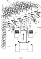
- the Fig. 1 schematically shows a first embodiment variant or the components of a Sternradschwaders invention 100, which is in use and is therefore pushed by a tractor 1 according to the invention in a direction of travel 17.
- the Sternradschwader 100 by means of a longitudinal member 3, in detail comprising a first single longitudinal member 30a and a second single longitudinal member 30b, fixed with a connecting cylinder 14 at a front three-point hitch 2 of the tractor 1.
- the longitudinal member 3 forms with a cross member 4 a pivot point ALP and a working angle W 1 , which is less than 90 degrees.
- the Sternradschwader 100 is set back to the left and puts in so-called left-filing compartments feed 10 in a swath 11 from.
- support devices 5a and 5b are arranged, each with a free-running support wheel 9a and 9b. Furthermore, at the cross member 4 at a top 12 at regular intervals star wheels 8a-8f arranged overlapping, with the help of an L-shaped pendulum holder 6a-6f. Between the L-shaped pendulum holders 6a-6f and the star wheels 8a-8f individual drives 7a-7f are arranged, which are hydraulic, electrical, mechanical or pneumatic can.
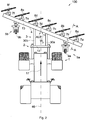
- a working angle W 2 is now greater than 90 degrees and a bottom 13 of the cross member 4 is now up.
- the connecting cylinder 14 is designed mirror-symmetrically, the star wheel 100 can be fixed to the three-point hitch 2 in this rotated by 180 degrees position.
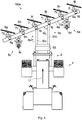
- the Fig. 3 schematically shows the support device 5a from the Fig. 2 , viewed from the right, as indicated by the section AA in this figure.
- two lugs 18 a and 18 b are welded to the cross member 4, in which a pin 19 is rotatably inserted and thus simultaneously two opposing tabs 20 a and 20 b combined to form a horizontal pivot 21.
- This horizontal pivot 21 is thus free-running about a vertical axis 26 rotating and thus always aligns itself against the direction of travel 17 from.
- the two counter-tabs 20a and 20b are arranged on a height adjustment 22, which comprises a threaded spindle 23 with an upper square 24a and a lower 24b. By rotation on one of the four edge 24a or 24b, a height adjustment of an L-shaped wheel holder 29 in an elevation axis 28 is thus achieved.
- a vertical pivot 25 is arranged, which allows rotation of the wheel holder 29 about a horizontal axis 27, preferably with latching positions P 1 and P 2 for the support wheel 9a in the vertical axis 26, the former latching position P 1 as shown by solid lines and the latter as indicated by dashed lines.
- the support wheel 9a has a wheel axle 31, which is preferably mounted on both sides.
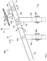
- a further, second embodiment variant of a Sternradschwaders 100a according to the invention shown extending from the Sternradschwader 100 of the FIGS. 1 and 2 differs in that on an otherwise same longitudinal beam 3a with a longitudinal axis 46a, a rotating device 32 for automatic mechanical rotation of the Sternradschwaders 100a is arranged by 180 degrees.
- the Sternradschwader 100a as before comprises two individual longitudinal members 30c and 30d, which form a linkage ALP 1 and a working angle W 3 with a cross member 4a.
- the Fig. 5 schematically shows a further, third embodiment variant of a Sternradschwaders invention 100b, in which a pivot point ALP 2 between a double longitudinal beam 3b and a cross member 4b is realized as a double pivot 33 and thus results in a variable operating angle W 4 .
- the double hinge 33 includes, for example, a fixed single joint. 34a and a variable individual joint 34b, which can compensate for the differences in length in a guide slot 35.
- the individual joints 34a and 34b are shown symbolically, the most suitable are probably joint claws as in cardan shafts, the upper and lower sides of the cross member 4b grasp.
- a left single side member 30e and a right single side member 30f are telescopically configured and each lockable with locking pins 36a and 36b.
- the telescopic configuration of the left individual longitudinal member 30e is optional, but, if desired, allows the cross member 4b or the star wheel raker 100b to be rotated through 180 degrees and thus placed on the individual longitudinal members 30e and 30f.
- each individual L-shaped pendulum holder 6m can be arranged on an upper side 12b of the cross member 4b in a pivot bearing 37 and thereby a star wheel 8m including a single drive 7m in an angle of attack W. St is variable to the direction of travel 17.
- a transport position 200 is realized.
- a cross member 4 c has two folding arms 38 a and 38 b, which are pivotable in hinged joints 39 a and 39 b more than 90 degrees and supported on not shown stops and alone due to the weight of the folding arms 38 a and 38 b in this transport position 200 also remain.
- it can also be arranged hydraulic cylinder, which not only accomplish the unfolding, but also holding in the unfolded position.
- stops 38a and 38b may also be provided for the unfolded, horizontal operating position of the folding arms 38a.
- a Sternradschwader variant with improved adaptation to the soil profile cross-section can be realized, according to paragraph [0031].
- Fig. 7 shows schematically and only partially a fifth embodiment variant of a Sternradschwaders invention 100d, in which a transport position 200a is achieved by a cross member 4d on each side of a single longitudinal member 30g each have a telescopic socket 40 from which a telescopic arm 41 in the operating position off and in the transport position 200a is retractable, preferably hydraulically.
- Transversely through the cross member 4d both by the Teleskop charged 40, as well as by the Teleskoparm 41 a preferably double rail 42 is laid in the example only by reference to each L-shaped pendulum holder 6n and 6o and arranged thereon individual drives 7n and 7o shown is that they are displaceable by means of carriages 43a and 43b. In this way, it is possible to set a distance D between the individual star wheels or the degree of overlap for all other cross member designs and then fix them with screws 44a-44d, for example.
- Fig. 8 schematically shows a sixth embodiment variant of a further Sternradschwaders invention 100e partial representation, which comprises a double pivot 33a and thus with positive, negative, but also, as shown, with an approximately right working angle W 5 can be operated.
- Two individual side members 30h and 30i have a pivot point ALP 2 with a cross member 4e on which in turn, in each case in pivot bearings 37a-37i, two parallel rows R 1 and R 2 are arranged by star wheels.
- the star wheels of the series R 2 are preferably fastened with quick-release fasteners 45a-45d. In this way, on the one hand in the direction of travel 17, the actual maximum working width of the cross member 4 e can be exploited and on the other hand, the star wheels can be varied in their angle of attack.
- Fig. 9 shows schematically that in a seventh by means of figures illustrated or indicated Design variant of Sternradschwaders invention 100f operating the star wheels exactly transverse to the direction of travel 17 - such as in Fig. 8 shown - improved by a so-called positive fall St +. So bent, a star wheel 8u glides better over a ground B, because it does not get caught and thus better absorbs crop 10a.
- an L-shaped pendulum holder 6p with oblique axis alignment can be arranged on a cross member 4f and drive the star wheel 8u via a single drive 7p.
Landscapes
- Life Sciences & Earth Sciences (AREA)
- Environmental Sciences (AREA)
- Soil Working Implements (AREA)
- Agricultural Machines (AREA)
Description
Die vorliegende Erfindung betrifft einen Schwader, also ein landwirtschaftliches Gerät zum Sammeln bzw. Zusammenfassen von geschnittenem Futtergut wie z.B. Gras, Silage, Heu, Stroh usw. und zum Ablegen in meist parallel angehäuften Reihen, den sogenannten Schwaden. Diese können dann mit einer Ballenpresse, einem Feldhäcksler oder einem Ladewagen aufgenommen werden. Außerdem wird das Futter bzw. Anwelkgut auch abends in diese Form gebracht, damit es vor dem nächtlichen Tau besser geschützt wird und der Boden morgens besser abtrocknen kann, bevor das Halmgut anschließend wieder mit einem Heuwender gleichmäßig verteilt wird, damit es weitertrocknen kann.The present invention relates to a rake, that is to say an agricultural device for collecting cut fodder such as e.g. Grass, silage, hay, straw, etc. and for laying down in mostly parallel accumulated rows, the so-called swaths. These can then be picked up with a baler, a forage harvester or a self-loading wagon. In addition, the food or Anwelkgut is also brought in the evening in this form, so it is better protected from the nocturnal dew and the soil can dry better in the morning, before the stalk is then distributed evenly with a tedder, so that it can continue to dry.
Es gibt unterschiedliche Bauarten von Schwadern, wobei sogenannte Kreiselschwader die am häufigsten verbreiteten sind. Sie besitzen einen oder mehrere horizontale Kreisel mit 6 bis 16 Zinkenarmen, die über die Zapfwelle oder die Hydraulikanlage des Traktors angetrieben werden. Im Falle von mehreren Kreiseln erfolgt der Antrieb simultan und mit identischem Drehmoment und mit identischer Drehzahl an allen Kreiseln. Unter bestimmten Einsatzbedingungen kann dieses einen Nachteil darstellen.There are different types of rakes, with so-called rotary rakes are the most common. They have one or more horizontal rotors with 6 to 16 tine arms, which are driven by the PTO or hydraulic system of the tractor. In the case of multiple rotors, the drive is simultaneous and with identical torque and at the same speed on all rotors. Under certain conditions of use, this can be a disadvantage.
Sternradschwader haben 3-20 Zinkenräder, eben Sternräder genannt, die bodengetrieben sind, indem der Traktor sie frei laufend über den Boden zieht. Bei diesem Schwadertyp ist es vorteilhaft, dass sich die Sternräder dem Boden gut anpassen und insbesondere leichteres Erntegut sehr schonend behandelt wird. Weitere Vorteile sind der nur geringe Verschmutzungsgrad des Ernteguts mit Erde und die hohe Arbeitsleistung aufgrund hoher Arbeitsgeschwindigkeit. Nachteilig allerdings ist bei Sternradschwadern die schlechtere Eignung für schweres oder nasses Mähgut und die generelle Neigung, das Schwadgut zu einem Zopf zu verflechten, was die spätere Aufnahme deutlich erschwert.Sternradschwader have 3-20 zinc wheels, just called star wheels, which are ground-driven by the tractor pulls them running freely over the ground. In this type of swath, it is advantageous that the star wheels adapt well to the soil and especially lighter crop is treated very gently. Further advantages are the low degree of contamination of the crop with soil and the high performance due to high working speed. A disadvantage, however, is in Sternradschwadern the poorer suitability for heavy or wet crop and the general tendency to intertwine the Schwadgut to a braid, which makes the subsequent recording much more difficult.
Weitere bauartbedingte Nachteile von Sternradschwadern zeigen sich insbesondere in hügeligem Gelände oder Hanglagen. Dadurch, dass die Sternräder bodengetrieben laufen, liegt ihre optimale Arbeitsleistung bei einem guten Mittelwert zwischen zu geringem Vortrieb, was wiederum geringer oder zu geringer Rotationskraft entspricht, und zu hohem Vortrieb, was zwar hohe Rotationskraft ergibt, aber wegen zu großer Wegzurücklegung wiederum ineffizient ist. Jedenfalls liegt dieser optimale Vortrieb der Sternräder, sprich die Fahrtgeschwindigkeit des meist ziehenden Traktors, beträchtlich hoch. Für hügeliges Gelände oder Hanglagen, vielleicht noch rutschige, oft zu hoch. Der Landwirt bzw. Fahrer des Traktors verlangsamt dann die Fahrtgeschwindigkeit, handelt sich aber dadurch zwangsläufig eine Verschlechterung der Arbeitsleistung der Sternräder ein.Other design-related disadvantages of Sternradschwadern show up particularly in hilly terrain or slopes. The fact that the star wheels run floor-mounted, their optimal performance is a good average between too little propulsion, which in turn corresponds to low or too low rotational force, and too high propulsion, which, although high rotational force, but inefficient due to excessive distance. In any case, this optimal propulsion of the star wheels, that is, the speed of the tractor most pulling, is considerably high. For hilly terrain or slopes, maybe still slippery, often too high. The farmer or driver of the tractor then slows down the speed of travel, but this is inevitably a deterioration of the performance of the star wheels.
Ein weiterer Nachteil in der Anwendung von Sternradschwadern kann in Hanglagen auftreten, wenn beispielsweise die erste, oberste Schwade hangaufwärts gelegt werden soll, weil man die Fahrt mit dem Traktor im allerhöchsten und steilsten Gelände vermeiden will. Hangaufwärts nämlich arbeiten die herkömmlichen Sternradschwader weniger gut.Another disadvantage in the application of Sternradschwadern can occur on slopes, for example, if the first, top swath is to be placed uphill, because you want to avoid the drive with the tractor in the highest and steepest terrain. Upstream, the conventional star wheel swathers work less well.
Weiterhin werden die herkömmlichen Sternradschwader vom vorausfahrenden Traktor gezogen. Der Traktor fährt also über das ausgebreitete Futter drüber. Dieses ist für das Futter unter Umständen von Nachteil, wenn der Druck der Traktorreifen es mit feuchter Erde vermischt oder in sie hineindrückt. Außerdem ist es eventuell von Nachteil für die Arbeitseffizienz der Sternräder oder einer anschließenden Aufnahme, weil das Futter durch die Last des Traktors zusammen- und auf den Boden angepresst ist.Furthermore, the conventional star wheel rakes are pulled by the tractor in front. The tractor drives over the spreaded food over it. This may be detrimental to the feed if the pressure of the tractor tires mixes with or pushes into moist soil. In addition, it may be detrimental to the working efficiency of the starwheels or subsequent picking because the feed is compressed by the load of the tractor and pressed against the ground.
Dadurch, dass bei herkömmlichen Sternradschwadern die Sternräder freilaufend bodengetrieben sind, benötigen sie einen relativ großen Anstellwinkel, damit ihr Ziehen über den Boden auch in eine Drehung umgesetzt wird. Dieser Anstellwinkel wird üblicherweise erreicht, indem der oder die Querträger des Sternradschwaders schräg oder V-förmig angeordnet sind, was wiederum zu Lasten der maximalen möglichen Arbeitsbreite geht.The fact that the star wheels are freewheeling floor-mounted in conventional star wheel rakes, they require a relatively large angle of attack, so that their pulling over the ground is also converted into a rotation. This angle of attack is usually achieved by the or the cross member of the Sternradschwaders are arranged obliquely or V-shaped, which in turn is at the expense of the maximum possible working width.
Des Weiteren gibt es noch Bandrechschwader, Rotorschwader, Pick-Up-Bandschwader und Trommelschwader, denen aber allen gemeinsam ist, dass eine einzige, angetriebene Aufnahme-, Zinken- oder vielmehr Rechenvorrichtung vorgesehen ist. Gegenstand der vorliegenden Patentanmeldung ist insbesondere ein Sternradschwader, aber auch ein Kreiselschwader mit mehreren Kreiseln. Die im Folgenden offenbarte Erfindung wird hauptsächlich für einen Sternradschwader beschrieben, gilt aber gleichermaßen für einen Kreiselschwader mit mehreren Kreiseln offenbart.Furthermore, there are still Bandrechschwader, rotor rake, pick-up-Bandschwader and Trommelschwader, but all have in common that a single, driven recording, tine or rather computing device is provided. The subject matter of the present patent application is, in particular, a star wheel rake, but also a rotary rake with several rotors. The invention disclosed below is described primarily for a star wheel rake, but equally applies to a rotary rake with multiple rotors.
Die Aufgabe der vorliegenden Erfindung ist, einen Sternradschwader mit mehreren Sternräder zu stellen, der bei Bodenunebenheiten, Hanglagen und unterschiedlichem Mähgut optimal einsetzbar ist, bei gleichzeitig schonender Behandlung und geringem Verschmutzungsgrad des Futters, sowie bei hoher bzw. gesteigerter Arbeitseffizienz und natürlich unter weitestgehender Vermeidung der oben aufgezeigten, bauarttypischen Nachteile.The object of the present invention is to provide a Sternradschwader with multiple star wheels, which is optimally used in uneven ground, slopes and crops, at the same time gentle treatment and low degree of contamination of the feed, as well as high or increased work efficiency and of course, while largely avoiding identified above, type-typical disadvantages.
Die Lösung der Aufgabe besteht zunächst in der Realisierung eines Sternradschwaders mit mindestens je einem einzelnen Antrieb für jede einzelne Zinkenvorrichtung, also für jedes Sternrad separat.The solution to the problem consists initially in the realization of a star wheel rake with at least one individual drive for each individual tooth device, ie separately for each star wheel.
In einer Basis-Ausgestaltungsvariante eines erfindungsgemäßen Schwaders mit mindestens je einem Einzelantrieb für jede Zinkenvorrichtung sind die Einzelantriebe, sei es in Form eines Getriebes oder Motors, alle untereinander identisch und in Serie angeordnet. Hieraus resultiert in jeder Lage eine identische Umdrehungszahl und ein identisches Drehmoment für jede Zinkenvorrichtung.In a basic embodiment variant of a rake according to the invention with at least one each Single drive for each tine device are the individual drives, whether in the form of a gearbox or motor, all identical to each other and arranged in series. This results in each layer an identical number of revolutions and an identical torque for each tine device.
Eine weitere Ausgestaltungsvariante eines erfindungsgemäßen Schwaders sieht unterschiedliche Einzelantriebe vor, die jedoch von ihrer Anordnung oder vielmehr von ihrer Größe und Leistung her fix vorgegeben sind. So kann beispielsweise die erste Zinkenvorrichtung konstant mittels eines fixen Getriebes oder Motors immer mit der gleichen Drehzahl n1 angetrieben sein, während die zweite Zinkenvorrichtung beispielsweise mit einer größeren konstanten Drehzahl n2 und die dritte Zinkenvorrichtung beispielsweise mit einer nochmals größeren konstanten Drehzahl n3 angetrieben ist. Die unterschiedliche Drehzahl bzw. unterschiedliche Antriebskraft der einzelnen Zinkenvorrichtungen verhindert erfindungsgemäß die Zopfbildung.A further embodiment variant of a rake according to the invention provides for different individual drives, which, however, are predefined by their arrangement or rather by their size and performance. Thus, for example, the first tine device can be constantly driven by a fixed gear or motor always at the same speed n 1 , while the second tine device, for example, with a larger constant speed n 2 and the third tine device, for example, driven with a further larger constant speed n 3 , The different rotational speed or different driving force of the individual prongs devices according to the invention prevents plait formation.
Bei einer bevorzugten Ausgestaltungsvariante eines erfindungsgemäßen Schwaders jedoch sind die Einzelantriebe voll variabel und steuerbar. Der Fahrer ist weiterhin bevorzugt in der Lage, während der Fahrt bzw. Anwendung des Schwaders von der Fahrerkabine aus die Drehzahl und das Drehmoment jeder einzelnen Zinkenvorrichtung zu beeinflussen. Er kann so beispielsweise, je nach Bedarf, den inneren Zinkenvorrichtungen eine höhere Leistung geben als den äußeren oder umgekehrt oder - bei angewinkelter Stellung des Schwaders - den in Fahrtrichtung vorderen weniger und den hinteren steigend mehr, weil die hinteren Zinkenvorrichtungen nicht nur dasjenige Futtergut aufnehmen müssen, das vor ihnen liegt, sondern auch das Futtergut der vorderen zugerecht bekommen.In a preferred embodiment variant of a rake according to the invention, however, the individual drives are fully variable and controllable. The driver is also preferably able to influence the speed and torque of each individual tine device as the rake is driven from the cab. It can, for example, according to need, give the inner tine devices a higher performance than the outer or vice versa or - in angled position of the rake - the front less in the direction of travel and the rear rising more, because the rear tine devices must not only take that feed that lies in front of them, but also get the fodder of the front right.
Weiterhin ist es bevorzugt, den Schwader mit dem Traktor nicht zu ziehen, sondern vorzugsweise zu schieben und somit vorne an einem vorderen Dreipunktanbaubock des Traktors zu befestigen. Hierfür umfasst die Grundkonstruktion eines erfindungsgemäßen Schwaders einen Längsträger mit einem Anschluss, welcher den Anschlussvoraussetzungen und Abmessungen des vorderen Dreipunktanbaubocks eines Traktors entspricht. Gegenüberliegend, an dem vorderen Ende des Längsträgers, ist gemäß einer ersten Basis-Ausgestaltungsvariante ein Querbalken oder vielmehr Querträger in einem Anlenkpunkt fix angelenkt, vorzugsweise mit dem Längsträger einen Winkel - im Folgenden Arbeitswinkel genannt - bildend, der in einem Bereich von 0 bis 75 Grad liegt, vorzugsweise jedoch ca. 30 Grad beträgt.Furthermore, it is preferable not to pull the rake with the tractor, but preferably to push and thus to attach to the front of a front three-point hitch of the tractor. For this purpose, the basic construction of a rake according to the invention comprises a longitudinal member with a connection which corresponds to the connection requirements and dimensions of the front three-point hitch of a tractor. Opposite, at the front end of the longitudinal member, according to a first basic design variant, a crossbeam or rather cross member articulated fixed in a pivot point, preferably with the side member an angle - hereinafter called working angle - forming, in a range of 0 to 75 degrees is, but preferably about 30 degrees.
Wie also bereits erwähnt, wird ein erfindungsgemäßer Schwader vorzugsweise vor dem Traktor geschoben, genauso ist es aber auch möglich, ihn zu ziehen. Das Haupterfindungsmerkmal des Einzelantriebs pro Zinkenvorrichtung und die noch im Folgenden offenbarten Erfindungsmerkmale gelten für gezogene Schwadervarianten gleichermaßen, weil sie ohne erfinderisches Zutun übertragbar sind.As already mentioned, an inventive swather is preferably pushed in front of the tractor, but it is also possible to pull it. The main feature of the individual drive per tine device and the features of the invention disclosed below apply equally to trailed windrow variants, because they can be transferred without inventive step.
Der Längsträger kann ein Doppelträger aus zwei Einzelträgern sein, die parallel oder aber auch trapezförmig möglichst weit beabstandete Befestigungspunkte gewährleisten. Auf diese Weise können im Querträger bzw. Schwader auftretende Torsionskräfte bzw. sich aufschaukelnde Schwingungen am besten unterbunden werden.The longitudinal member may be a double carrier of two individual carriers, which ensure parallel or trapezoidal as far as possible spaced attachment points. In this way, occurring in the cross member or rake torsional forces or aufschaukelnde vibrations are best prevented.
An dem Querträger sind mindestens zwei, vorzugsweise jedoch mehrere Sternräder vorzugsweise überlappend angeordnet und dieses weiterhin erfingdungsgemäß mittels eines frei in einem Gelenk schwingenden L-förmigen Halters. Auf diese Weise sind die Sternräder pendelnd befestigt, indem sie je nach Bodendruck oder einer einzelnen Bodenunebenheit annähernd vertikal frei innerhalb des Bewegungsradius des L-förmigen Halters schwingen können.At least two, but preferably a plurality of starwheels are preferably arranged overlapping on the crossbeam and this furthermore according to the invention by means of an L-shaped holder swinging freely in a joint. In this way, the starwheels are mounted in a pendulum fashion by being able to oscillate approximately vertically freely within the range of movement of the L-shaped holder, depending on ground pressure or a single ground unevenness.
Gemäß einer besonderen Ausgestaltungsvariante eines erfindungsgemäßen Schwaders ist dieser L-förmige Pendelhalter der einzelnen Sternräder oder der einzelnen Kreisel federunterstützt. Auf diese Weise ist es einerseits möglich, die Anpassung der Sternräder an Bodenunebenheiten nicht alleine nur über das Eigengewicht des Sternrades zu regeln, sondern eben durch Federkraft unterstützt einen konstanteren Anpressdruck der Sternräder auf dem Boden zu erreichen. Andererseits kann auf diese Weise ein mögliches Springen der Sternräder vermieden werden, das, bedingt durch die elastischen Zinken, insbesondere bei höheren Arbeitsgeschwindigkeiten auftreten kann.According to a particular embodiment variant of a rake according to the invention, this L-shaped pendulum holder of the individual star wheels or the individual rotor is spring-assisted. In this way, it is on the one hand possible to regulate the adaptation of the star wheels to uneven floors not only on the weight of the star wheel, but just supported by spring force to achieve a more constant contact pressure of the star wheels on the ground. On the other hand, a possible jumping of the star wheels can be avoided in this way, which, due to the elastic prongs, can occur especially at higher operating speeds.
Eine nochmals ganz besondere Ausgestaltungsvariante eines erfindungsgemäßen Schwaders sieht für den federunterstützten L-förmigen Pendelhalter Federn mit einer degressiven Kennlinie vor. Dieses bewirkt, dass bei vergrößertem Federweg nicht auch der Anpressdruck steigt - und sich die Zinken des Sternrades unerwünschtermaßen noch tiefer in die Erde eingraben, sondern mit zunehmendem Federweg der Anpressdruck des Sternrades auf dem Boden abnimmt.Another very special embodiment variant of a rake according to the invention provides for the spring-assisted L-shaped pendulum holder springs with a degressive characteristic before. This causes that with increased travel not the contact pressure increases - and the tines of the star wheel undesirably dig deeper into the earth, but decreases with increasing travel of the contact pressure of the star wheel on the ground.
Des Weiteren sind an einem erfindungsgemäßen Schwader mindestens zwei Stützräder angeordnet, die vorzugsweise, z.B. mittels einer Gewindespindel, höhenverstellbar sind. Die Sternräder sind vorzugweise an der Vorderseite des Querträgers angeordnet und die Stützräder vorzugsweise nachlaufend an der Rückseite. Optional können die Stützräder ebenfalls gefedert sein.Furthermore, at least two support wheels are arranged on a swather according to the invention, which are preferably, e.g. by means of a threaded spindle, are height adjustable. The star wheels are preferably arranged at the front of the cross member and the support wheels preferably trailing at the back. Optionally, the support wheels can also be sprung.
Wenn sich der ca. 30-grädige Arbeitswinkel zwischen Längs- und Querträger links befindet, also der Querträger in Fahrtrichtung nach links angestellt ist und mit seinem rechten Ende weiter vorne ist, so ergibt sich ein erfindungsgemäß schiebender Schwader, der die Schwade links ablegt. Für eine grundsätzliche und ausschließliche Rechtsablage der Schwade ist es vorgesehen, eine spiegelverkehrte fixe Anordnung von Längs- und Querträger anzubieten, bei welcher der ca. 30-grädige Arbeitswinkel zwischen Längs- und Querträger dann eben rechts gebildet ist.If the approximately 30-grader working angle between the longitudinal and transverse members is left, so the cross member is employed in the direction of travel to the left and with his right end is further forward, so there is a sliding scraper according to the invention, which stores the swath left. For a fundamental and exclusive legal deposition of the swath, it is intended to use a mirror-inverted fixed arrangement of longitudinal and offer cross member, in which the approximately 30-grader working angle between the longitudinal and transverse beams is then formed just right.
Für mehr Flexibilität in der Anwendung, bzw., um dem Anwender die Wahlmöglichkeit zu geben, nach Bedarf und speziellen Einsatzvoraussetzungen zwischen Links- und Rechtsablage wechseln zu können, ist es bei einer weiteren Ausgestaltungsvariante eines erfindungsgemäßen Schwaders vorgesehen, ihn um 180 Grad um eine Längsachse des Längsträgers manuell drehen zu können und so gedreht ebenfalls anschließen zu können. Hierfür sind die Anschlüsse des Schwaders, die am Traktor vorzugsweise vorne am vorderen Dreipunktanbaubock angeschlossen werden, spiegelsymmetrisch ausgestaltet.For more flexibility in the application, or, in order to give the user the option to switch between left and right shelves as needed and special conditions of use, it is provided in a further embodiment variant of a rake according to the invention, it 180 degrees about a longitudinal axis to be able to turn the longitudinal member manually and thus also be able to connect in a rotated manner. For this purpose, the connections of the rake, which are preferably connected to the tractor front front three-point hitch, designed mirror-symmetrical.
Zur Erleichterung der Drehung, auch für die noch folgenden Ausgestaltungsvarianten eines erfindungsgemäßen Schwaders mit integrierter 180-Grad-Drehbarkeit um die Längsachse des Längsträgers, ist es vorgesehen, dass der Dreipunktanbaubock den gesamten Schwader so anheben kann, dass er frei in der Luft gedreht werden kann. Der Dreipunktanbaubock kann dieses sowieso in jedem Fall, entscheidend jedoch, im Hinblick auf die hier offenbarten Schwader, sind die Abmessungen, das Gewicht und der Schwerpunkt der Grundkonstruktion. Nur, um ein Beispiel zu nennen, muss die Länge des Längsträgers so ausgewählt sein, dass der Querträger im angehobenen Zustand beispielsweise an der Fahrerkabine des Traktors auch vorbeigedreht werden kann.To facilitate the rotation, even for the following design variants of a rake according to the invention with integrated 180-degree rotation about the longitudinal axis of the longitudinal member, it is envisaged that the three-point jack can lift the entire rake so that it can be freely rotated in the air , However, the three-point hitch can do this anyway, but crucially, in view of the rakes disclosed herein, the dimensions, weight and center of gravity of the basic design. Just to give an example, the length of the longitudinal member must be selected so that the cross member in the raised state, for example, on the cab of the tractor can also be rotated past.
Des Weiteren sind bei dieser Ausgestaltungsvariante in einer einfachsten Version nicht nur an der Unterseite des Querträgers Stützräder angeordnet, sondern auch an seiner Oberseite.Furthermore, in this embodiment variant in a simplest version not only on the underside of the cross member support wheels arranged, but also on its upper side.
Bei einer anderen Ausgestaltungsvariante eines erfindungsgemäßen Schwaders, der um 180 Grad um die Längsachse des Längsträgers von Linksablage auf Rechtsablage und umgekehrt schwenkbar ist, sind Stützräder in einem Schwenkgelenk an dem Querträger angeordnet, das ein Schwenken der Stützräder von der Unter- auf die Oberseite des Querträgers und umgekehrt erlaubt. Des Weiteren ist an diesem Schwenkgelenk eine Arretiervorrichtung angeordnet, um die Stützräder in der unteren oder oberen Schwenkposition zu fixieren.In another embodiment variant of a rake according to the invention, the 180 degrees about the longitudinal axis the longitudinal member of the left tray on right tray and vice versa is pivotally support wheels are arranged in a pivot joint on the cross member, which allows pivoting of the support wheels from the bottom to the top of the cross member and vice versa. Furthermore, a locking device is arranged on this pivot joint in order to fix the support wheels in the lower or upper pivot position.
Um den Schwader um 180 Grad um die Längsachse des Längsträgers zu drehen, kann an dem Längsträger gemäß einer weiteren Ausgestaltungsvariante eines erfindungsgemäßen Schwaders auch eine in den Längsträger integrierte, mechanische oder mechanisch-hydraulische Drehvorrichtung vorgesehen sein. Diese Drehvorrichtung kann ein annähernd halbkreisförmiges Zahnrad umfassen oder einen Schneckenantrieb, der mechanisch über eine Antriebswelle des Traktors oder über die Hydraulikanlage des Traktors angetrieben wird. Für die waagerechten Schwenk-Endpositionen des Querträgers bzw. für die Betriebspositionen des Schwaders kann mindestens eine Arretiervorrichtung vorgesehen sein, oder aber auch für Zwischenpositionen, bevorzugt ist es jedoch, den Schwader stufenlos verschwenken und in jeder beliebigen Schwenkposition auch halten zu können, um eine allfällige Schwenkwinkel-Anpassung des Schwaders an Hangneigungen vornehmen zu können.In order to rotate the rake about 180 degrees about the longitudinal axis of the longitudinal member, may be provided on the side member according to a further embodiment variant of a rake according to the invention also integrated into the longitudinal member, mechanical or mechanical-hydraulic rotary device. This rotating device may comprise an approximately semi-circular gear or a worm drive, which is driven mechanically via a drive shaft of the tractor or via the hydraulic system of the tractor. At least one locking device can be provided for the horizontal pivot end positions of the cross member or for the operating positions of the rake, or for intermediate positions, but it is preferred to be able to pivot the rake continuously and in any pivot position to hold a possible Swivel angle adaptation of the swather to be able to make slopes.
Vor dem Hintergrund, dass das Wenden des Schwaders um 180 Grad um die Längsachse des Längsträgers unter Umständen, je nach Größe und Gewicht des Schwaders, ein Problem darstellen könnte - insbesondere, sofern keine wie oben beschriebene Drehvorrichtung vorgesehen ist -, sieht eine weitere Ausgestaltungsvariante eines erfindungsgemäßen Schwaders im Anlenkpunkt zwischen Längs- und Querträger keine fixe Befestigung mehr vor, sondern ein Drehgelenk bzw. ein doppeltes Drehgelenk im Falle eines doppelten Längsträgers. Dieses Drehgelenk ist in einer einfacheren Version vorzugsweise nicht nur in einer grundsätzlichen Links- und Rechtsablage-Stellung arretierbar, sondern auch in einzelnen Stufen mit unterschiedlichen Arbeitswinkeln.Against the background that the turning of the rake about 180 degrees about the longitudinal axis of the longitudinal beam under certain circumstances, depending on the size and weight of the rake, could be a problem - especially, if no rotary device as described above is provided - sees a further embodiment variant of Schwaders according to the invention in the point of articulation between the longitudinal and transverse beams no more fixed attachment before, but a rotary joint or a double swivel joint in the case of a double longitudinal member. This swivel is in a simpler version, preferably not only in a basic left and Rechtsablage position Lockable, but also in individual stages with different working angles.
Eine einfachste Version eines solchen doppelten Drehgelenkes lässt sich von Hand mechanisch verstellen, indem die beiden einzelnen Längsträger, welche den Doppelträger bilden, in ihrer Länge adaptierbar sind. Dieses wiederum kann teleskopartig erfolgen und mit Arretierbolzen gesichert sein. Um die beiden einzelnen Längsträger beim Verschwenken des Querträgers bzw. bei dem so erfolgenden Einstellen des gewünschten Arbeitswinkels nicht biegen zu müssen, ist vorzugsweise mindestens eines der Einzelgelenke in einer langlochartigen Führung verschiebbar gelagert. Es kommt aber auch ein Doppelträger mit hydraulischen Zylindern in Betracht, sodass wie bei einem Pflug die Schar stufenlos und sogar während des Fahrens beliebig nach links oder rechts ausgerichtet werden kann.A simplest version of such a double hinge can be mechanically adjusted by hand, in that the two individual side members, which form the double carrier, are adaptable in their length. This in turn can be done telescopically and secured with locking bolts. In order not to have to bend the two individual longitudinal members during pivoting of the cross member or in the so taking place setting the desired working angle, preferably at least one of the individual joints is slidably mounted in a slot-like guide. But it is also a double carrier with hydraulic cylinders into consideration, so that as in a plow, the crowd can be aligned continuously and even while driving any left or right.
Ein erfindungsgemäßer Schwader zeichnet sich durch eine Transportstellung aus. Um die Gesamtbreite des Schwaders unter Straßenfahrbahnbreite bzw. annähernd auf Traktorenbreite zu bekommen, sind an dem Querträger vorzugsweise mindestens zwei Klappgelenke vorgesehen. Auf diese Weise können das linke und rechte Ende des Querträgers, wie Klapparme, wenn man so will, vorzugsweise inklusive der daran befestigten Sternräder aufgeklappt werden, vorzugsweise über 90 Grad hinaus und weiterhin vorzugsweise mit einer Sicherung gegen selbsttätiges Öffnen gesichert. Das Betätigen der Klapparme kann grundsätzlich von Hand, aber auch jeweils mittels eines Hydraulikzylinders erfolgen. Für die geöffnete, waagerechte Betriebsposition der Klapparme ist an den Klappgelenken vorzugsweise jeweils ein Anschlag vorgesehen, der für die Klapparme einen gesicherten und stabilen Halt in diesen Betriebspositionen garantiert.An inventive rake is characterized by a transport position. In order to get the total width of the rake under road lane width or approximately to tractor width, preferably at least two hinged hinges are provided on the cross member. In this way, the left and right end of the cross member, such as folding arms, if you will, preferably including the attached star wheels are opened, preferably over 90 degrees and further preferably secured with a safeguard against self-opening. The actuation of the folding arms can basically be done by hand, but also in each case by means of a hydraulic cylinder. For the open, horizontal operating position of the folding arms, a stop is preferably provided on the folding joints, which guarantees a secure and stable hold in these operating positions for the folding arms.
Alternativ können die Klappgelenke selbst jedoch so stabil ausgestaltet sein, dass der oben beschriebene Anschlag entfallen kann und die Klapparme sogar während des Betriebs frei schwingend bleiben. Auf diese Weise wäre es möglich, in besonders hügeligem Gelände eine gute Bodenanpassung zu erreichen, weil der Querträger sich dem Bodenprofil-Querschnitt beziehungsweise den jeweiligen Tälern oder Erhebungen laufend anpasst.Alternatively, however, the hinged joints themselves can be made so stable that the stop described above can be omitted and remain the swing arms even during operation free swinging. In this way it would be possible to achieve a good ground adaptation in particularly hilly terrain, because the cross member continuously adapts to the soil profile cross section or the respective valleys or elevations.
Weiterhin alternativ kann eine Transportstellung auch realisiert sein, indem der Querträger an seinen Enden ausfahrbare Teleskoparme aufweist. Die L-förmigen Pendelhalter der Sternräder sind dabei inklusive der Sternräder in einer integrierten Schiene des Querträgers verschieb- und fixierbar, die gleichermaßen durch eine Fassung für die Teleskoparme und die Teleskoparme selbst verläuft. Es kommt ein händisches Ausfahren der Teleskoparme und ebenfalls ein händisches Einstellen der L-förmigen Pendelhalter innerhalb der Schiene in Betracht, allerdings sind auch hydraulisch unterstützte Varianten denkbar und sogar eine, bei der die Fassung der ausfahrbaren Teleskoparme selber ein größerer doppelter Hydraulikzylinder ist und die ausfahrbaren Teleskoparme die Kolben.Further alternatively, a transport position can also be realized by the cross member has extendable telescopic arms at its ends. The L-shaped pendulum holder of the starwheels are including the star wheels in an integrated rail of the cross member displaced and fixable, which runs equally through a socket for the telescopic arms and the telescopic arms themselves. It comes a manual extension of the telescopic arms and also a manual setting of the L-shaped pendulum holder within the rail into consideration, but also hydraulically assisted variants are conceivable and even one in which the version of the telescopic telescopic arms itself is a larger double hydraulic cylinder and the extendable Telescopic arms the pistons.
Unabhängig von der Ausgestaltung des Querträgers mit ein- und ausfahrbaren Teleskoparmen für eine Transport- und eine Betriebsstellung, können alle in der vorliegenden Anmeldung offenbarten Querträger mit so einer Schienenführung für die L-förmigen Pendelhalter ausgestattet sein. Von Hand oder mittels eines seitlich angeordneten Hebelwerks für alle L-förmigen Pendelhalter oder auch hydraulisch unterstützt kann dann die Weite zwischen den Sternrad-Achsnaben bzw. der Grad der Überlappung der Sternräder innerhalb eines bestimmten Bereichs justiert werden, je nach speziellen Anforderungen und vielleicht auch je nach Länge und Gewicht des Schnittguts.Regardless of the design of the cross member with retractable telescopic arms for a transport and an operating position, all disclosed in the present application cross member may be equipped with such a rail guide for the L-shaped pendulum holder. By hand or by means of a laterally arranged lever mechanism for all L-shaped pendulum holders or hydraulically assisted, the width between the star wheel axle hubs or the degree of overlapping of the star wheels can then be adjusted within a certain range, depending on the particular requirements and perhaps also each according to length and weight of the cuttings.
Die Anordnung der einzelnen Sternräder am Querträger eines erfindungsgemäßen Sternradschwaders betreffend, so können sie fix in einem bestimmten Anstellwinkel zum Querträger in den L-förmigen Pendelhaltern angeordnet sein. Gemäß einer wiederum bevorzugten Ausgestaltungsvariante eines erfindungsgemäßen Sternradschwaders sind die L-förmigen Pendelhalter jedoch mittels eines Drehlagers in einer waagerechten Ebene am Querträger dreh- und arretierbar. Diese Verstellmöglichkeit des Anstellwinkels der Sternräder kann beispielsweise sehr einfach realisiert sein, indem die L-förmigen Pendelhalter mittels eines beispielsweise sechskantigen Schaftes in einer entsprechend formschlüssig sechskantigen Aufnahme im Querträger umsteckbar sind. Auf diese Weise kann einfach gewählt werden zwischen mehreren negativen Anstellwinkel-Positionen der Sternräder, einer zum Querträger parallelen Ausrichtung und positiven Anstellwinkel-Positionen. Selbstverständlich ist hiermit jedoch auch eine beliebige, nicht an vorgegebene Einzelpositionen gebundene Dreh- und Fixierbarbarkeit der L-förmigen Pendelhalter offenbart, beispielsweise mittels runden zylindrischen Schäften und weiterhin beispielsweise mit einem Arretierbolzen, der in vorzugsweise schraubenlinienförmig angeordneten Arretierbohrungen in Schaft und Aufnahme einsetzbar ist.The arrangement of the individual star wheels on the cross member of a Sternradschwaders invention, so can they can be arranged fixed in a certain angle to the cross member in the L-shaped pendulum holders. According to a again preferred embodiment variant of a Sternradschwaders invention, however, the L-shaped pendulum holder are rotatable and lockable by means of a pivot bearing in a horizontal plane on the cross member. This adjustment of the angle of attack of the starwheels, for example, be very easy to implement by the L-shaped pendulum holder by means of, for example, a hexagonal shank in a correspondingly form-fitting hexagonal recording in the cross member can be moved. In this way, it is easy to choose between several negative pitch positions of the starwheels, an orientation parallel to the crossbeam, and positive pitch positions. Of course, however, this also any, not bound to predetermined individual positions rotational and fixability of the L-shaped pendulum holder disclosed, for example by means of round cylindrical shanks and, for example, with a locking pin, which is preferably used in helically arranged locking holes in the shaft and recording.
Weil die einzelnen Sternräder vorzugsweise überlappend angeordnet sind, ist es bei der eben beschriebenen, aber auch insbesondere bei der in den Absätzen [0028] und [0029] beschriebenen Ausgestaltungsvariante mit einem Drehgelenk für Links- und Rechtsablage vorgesehen, vorzugsweise mindestens jedes zweite Sternrad - oder auch alle - mit einem axialen Schnellverschluss auszustatten. Dadurch können mindestens diese Sternräder leicht abgenommen werden und die Überlappungen stehen sich beim Umsetzen oder Schwenken von negativem zu positivem Anstellwinkel oder umgekehrt nicht im Weg.Because the individual starwheels are preferably arranged overlapping, it is provided in the just described, but also in particular in the paragraph described in paragraphs [0028] and [0029] embodiment variant with a hinge for left and right shelf, preferably at least every other star wheel - or also all - equipped with an axial quick release. As a result, at least these star wheels can be easily removed and the overlaps are not in the way when moving or pivoting from negative to positive angle or vice versa.
Eine weitere Ausgestaltungsvariante eines erfindungsgemäßen Sternradschwaders kann mit maximaler Arbeitsbreite betrieben werden, also mit einem annähernd rechten Arbeitswinkel gebildet zwischen Längs- und Querträger. Hierbei können die Sternräder natürlich in einem Anstellwinkel fix oder wie oben beschrieben verstellbar angeordnet sein, in letzter Konsequenz hingegen jedoch parallel zu dem Querträger und eine Überlappung dadurch erreichend, indem sie in zwei parallelen Reihen angeordnet sind. Hierfür müssen lediglich die L-förmigen Pendelhalter für die vom Querträger weiter entfernt angeordnete Reihe länger ausgestaltet sein, sofern beide Reihen beispielsweise an der frontseitigen Stirnseite des Querträgers vorgesehen sind. Es wäre aber auch möglich, mit identischen L-förmigen Pendelhaltern, eine erste Reihe an der Vorder- und eine zweite Reihe an der Rückseite des Querträgers vorzusehen.A further embodiment variant of a Sternradschwaders invention can be operated with maximum working width, ie formed with an approximately right working angle between longitudinal and transverse beams. in this connection Of course, the starwheels may be fixedly arranged at an angle of attack or may be adjustably arranged as described above, but in the final consequence, however, parallel to the crossbeam and achieving an overlap by being arranged in two parallel rows. For this purpose, only the L-shaped pendulum holder for the more distant from the cross member row must be designed longer, if both rows are provided for example on the front end side of the cross member. But it would also be possible to provide with identical L-shaped shuttle holders, a first row on the front and a second row on the back of the cross member.
Weiterhin wäre es für ein verbessertes Vorwärtsschieben der dann zur Fahrtrichtung exakt quer stehenden Sternräder möglich, sie mit einem positiven Sturz zu befestigen, d.h., dass sie oben nach vorne geneigt sind und unten ein bisschen zurückversetzt sind.Further, for improved forward sliding of the star wheels, which would then be exactly transverse to the direction of travel, it would be possible to secure them with a positive camber, i.e., they are inclined forward at the top and slightly recessed at the bottom.
Der Einzelantrieb der jeweiligen einzelnen Zinkenvorrichtungen erfolgt in einer bevorzugten Ausgestaltungsvariante hydraulisch, angeschlossen an und steuerbar durch die traktoreigene Hydraulikanlage, sofern vorhanden. Für kleinere Traktoren ohne Hydraulikanlage kann der Schwader einen Hydrauliköltank und eine Hydraulikpumpe umfassen, die an der Zapfwelle anschließbar ist und so einen schwadereigenen Hydraulikkreislauf ergibt. In beiden Fällen jedenfalls ist an jeder Zinkenvorrichtung je eine Einzel-Antriebseinheit in Gestalt eines Hydraulikmotors angeordnet, als sogenannter Konstantmotor für die in den Absätzen [0012] und [0013] beschriebenen fix vormontierten Ausgestaltungsvarianten und als sogenannter Verstellmotor für die in Absatz [0014] beschriebene, variable und separat ansteuerbare Ausgestaltungsvariante.The individual drive of the respective individual tine devices takes place hydraulically in a preferred embodiment variant, connected to and controllable by the tractor's own hydraulic system, if present. For smaller tractors without hydraulic system, the rake can include a hydraulic oil tank and a hydraulic pump, which can be connected to the PTO shaft and thus results in a ram's own hydraulic circuit. In each case, in each case, a single drive unit in the form of a hydraulic motor is arranged on each tine device, as a so-called constant motor for the fixed pre-assembled design variants described in paragraphs [0012] and [0013] and as a so-called variable motor for those described in paragraph [0014] , variable and separately controllable design variant.
Der erfindungsgemäße Einzelantrieb pro Zinkenvorrichtung kann weiterhin erfindungsgemäß aber auch elektrisch erfolgen. Hierfür umfasst jede Einzel-Antriebseinheit einen ungeregelten Elektromotor oder einen Elektroantrieb, der neben dem Elektromotor auch eine Regelung umfasst. Mit einzelnen Elektroantrieben ist eine variable Ansteuerung jeder Zinkenvorrichtung natürlich gut realisierbar.The individual drive according to the invention per tine device can also according to the invention but also done electrically. For this purpose, each individual drive unit comprises an unregulated electric motor or an electric drive, which also includes a control in addition to the electric motor. With individual electric drives a variable control of each tine device is of course well feasible.
Nicht außer Betracht für den erfindungsgemäßen Einzelantrieb pro Zinkenvorrichtung fallen aber auch rein mechanische Ausgestaltungsvarianten. So kann die Rotationskraft der Zapfwelle des Traktors abgegriffen werden und beispielsweise mittels Winkelgetriebe, T-Getriebe, Schnecken-, Ketten- oder Kardanwellenantrieb realisiert sein.Not out of consideration for the individual drive according to the invention per tine device but fall purely mechanical design variants. Thus, the rotational force of the PTO of the tractor can be tapped and realized for example by means of angular gear, T-gear, worm, chain or cardan shaft drive.
Da moderne Traktoren auch ein pneumatisches Druckluftsystem haben, kommt auch ein pneumatischer Einzelantrieb der Sternräder in Betracht. Hierbei treibt vorzugsweise je ein Luftdruckstrahl je ein vorzugsweise achsnah am Sternrad angeordnetes Turbinenrad an. Dieses pneumatische Antriebssystem kann vorzugsweise sogar offen sein, d.h., der antreibende Luftdruckstrahl kann nach Passieren des Turbinenrades ins Freie entweichen. Darüber hinaus kann ein Teil-Luftdruckstrahl abgezweigt und schräg auf den Boden gelenkt werden, sodass insbesondere schweres Mähgut für eine verbesserte Aufnahme durch die Zinken angelupft wird. Diese Anlupf-Funktion soll sich von der Intensität her allerdings auch nur darauf beschränken, weil das Wegblasen von Mähgut beispielsweise mittels Laubbläsern ökologisch zweifelhaft ist. Der beschriebene pneumatische Einzelantrieb könnte jedoch seine Vorteile gerade unter ökologischen Gesichtspunkten haben, weil das System einfach ist und komplett ohne grundwasserverschmutzendem Hydraulik-, Schmieröl oder -fett auskommt.Since modern tractors also have a pneumatic compressed air system, a pneumatic single drive of the star wheels is also possible. In this case, preferably one air-jet each drives a turbine wheel preferably arranged close to the axis of the star wheel. This pneumatic drive system may preferably even be open, i.e., the driving air pressure jet may escape to the atmosphere after passing the turbine wheel. In addition, a partial air pressure jet can be branched off and directed obliquely to the ground, so that in particular heavy crop is hooked on for improved absorption by the tines. This Anlupf function should be limited in intensity but only on this, because the blowing away of crops, for example by means of leaf blowers is ecologically dubious. However, the pneumatic single drive described could have its advantages just under ecological aspects, because the system is simple and completely manages without groundwater polluting hydraulic, lubricating oil or grease.
Die Energiespeisung der Einzelantriebe betreffend, sind einfach so flexible Hydraulik-, elektrische Leitungen, Kardanwellen oder Luftdruckschläuche zwischen Querträger und Einzelmotor bzw. Einzelantriebseinheit vorgesehen, die ohne Weiteres die Pendelbewegungen des Pendelhalters mitmachen.Regarding the energy supply of the individual drives, simply flexible hydraulic, electrical lines, cardan shafts or air pressure hoses between cross member and single motor or single drive unit are provided without Join in the pendulum movements of the pendulum holder.
Ein erfindungsgemäßer Schwader umfasst in einer letzten Ausgestaltungsvariante eine Freilaufvorrichtung für alle einzelangetriebenen Zinkenvorrichtungen. Dieses kann vorzugsweise eine simultan für alle Achsnaben der Zinkenvorrichtungen wirkende mechanische, elektromechanische oder hydraulische Kupplung sein, die eine axial translatorische Bewegung der Zinkenvorrichtungs-Achsnabe in eine zwangsangetriebene und in eine frei laufende Stellung ermöglicht. Die Freilaufvorrichtung ist vorzugsweise zentral von der Fahrerkabine aus bedienbar. Dadurch kann der Einzelantrieb je nach Einsatzvoraussetzungen oder je nach Belieben ausgeschaltet werden und der erfindungsgemäße Schwader auch "klassisch" nur bodengetrieben eingesetzt werden.A rake according to the invention comprises in a last embodiment variant a free-wheeling device for all individually driven tine devices. This may preferably be a mechanical, electromechanical or hydraulic coupling acting simultaneously on all axle hubs of the tine devices, which enables an axial translational movement of the tine device axle hub into a positively driven and a free running position. The freewheel device is preferably operated centrally from the driver's cab. As a result, the individual drive can be switched off depending on the conditions of use or at will, and the rake according to the invention can also be used "floor-mounted" "classic".
Die vorliegende Anmeldung offenbart ein erstes Verfahren zum Zusammenrechen von Mähgut zu Schwaden bzw. zum Einsatz eines erfindungsgemäßen Sternradschwaders, mit folgenden grundsätzlichen Verfahrensschritten:
- a) - Anschließen des Sternradschwaders an einen vorderen Dreipunktanbaubock eines Traktors;
- b) - falls erforderlich, manuelles oder hydraulisches Verstellen des Sternradschwaders aus einer Transportstellung in eine Betriebsstellung;
- c) - Auswählen eines Arbeitswinkels gebildet zwischen einem Längsträger und einem Querträger, für Links- oder Rechtsablage der Schwade;
- d) - falls erforderlich, Anheben des Sternradschwaders durch Betätigen des Dreipunktanbaubocks;
- e) - falls erforderlich, Betätigen einer Drehvorrichtung, die den Sternradschwader um 180 Grad um eine Längsachse des Längsträgers dreht;
- f) - falls erforderlich, Schwenken von Stützrädern in einem Vertikal-Drehgelenk auf eine gegenüberliegende Seite des Querträgers und Arretieren der Stützräder in dieser Schwenkposition;
- g) - falls erforderlich, Absenken des Sternradschwaders durch Betätigen des Dreipunktanbaubocks;
- h) - Höhenjustieren der Stützräder durch Betätigen einer Gewindespindel an den Stützvorrichtungen;
- i) - falls vorgesehen, Betätigen einer Kupplung zum Umschalten der Sternräder von Freilauf auf Zwangseinzelantrieb;
- j) - Losfahren mit dem Traktor.
- a) - connecting the star wheel rake to a front three-point hitch of a tractor;
- b) - if necessary, manual or hydraulic adjustment of the Sternradschwaders from a transport position to an operating position;
- c) - selecting a working angle formed between a side member and a cross member, for left or right placement of the swath;
- d) - if necessary, lifting the star wheel rake by operating the three-point mounting jib;
- e) - if necessary, operating a turning device which rotates the star wheel rake through 180 degrees about a longitudinal axis of the longitudinal member;
- f) - if necessary, pivoting of support wheels in a vertical pivot on an opposite side of the cross member and locking the support wheels in this Pivoted position;
- g) - if necessary, lowering the starwheel rake by operating the three-point extension jib;
- h) - adjusting the height of the support wheels by operating a threaded spindle on the support devices;
- i) - if provided, actuating a clutch for switching the star wheels from freewheel to forced single drive;
- j) - Starting with the tractor.
Die vorliegende Anmeldung offenbart ein zweites Verfahren zum Zusammenrechen von Mähgut zu Schwaden bzw. zum Einsatz eines weiteren erfindungsgemäßen Sternradschwaders, mit folgenden grundsätzlichen Verfahrensschritten:
- a') - Anschließen des Sternradschwaders an einen vorderen Dreipunktanbaubock eines Traktors;
- b') - falls erforderlich, manuelles oder hydraulisches Verstellen des Sternradschwaders aus einer Transportstellung in eine Betriebsstellung;
- c') - Auswählen eines Arbeitswinkels gebildet zwischen einem Längsträger und einem Querträger, für Links- oder Rechtsablage der Schwade;
- d') - falls erforderlich, Anheben des Sternradschwaders durch Betätigen von Gewindespindeln an Stützvorrichtungen oder durch Betätigen des Dreipunktanbaubocks;
- e') - falls erforderlich, Betätigen eines Drehgelenks zum Verändern des Arbeitswinkels zwischen dem Längsträger und dem Querträger;
- f') - falls erforderlich, Lösen und Entfernen derjenigen Sternräder, die mit einem Schnellverschluss befestigt sind durch Öffnen des Schnellverschlusses;
- g') - falls erforderlich, Ausrichten oder Umstellen der Anstellwinkel der Sternräder durch Betätigen eines jeweiligen Drehlagers an jeweiligen L-förmigen Pendelhaltern der Sternräder;
- h') - Zurückmontieren der entfernten Sternräder durch Aufsetzen der Sternräder und Schließen der Schnellverschlüsse;
- i') - falls erforderlich, Absenken des Sternradschwaders durch Betätigen des Dreipunktanbaubocks;
- j') - Höhenjustieren der Stützräder durch Betätigen der Gewindespindel der Stützvorrichtungen;
- k') - falls vorgesehen, Betätigen einer Kupplung zum Umschalten der Sternräder von Freilauf auf Zwangseinzelantrieb;
- l') - Losfahren mit dem Traktor.
- a ') - connecting the starwheel rake to a front three-point hitch of a tractor;
- b ') - if necessary, manual or hydraulic adjustment of the Sternradschwader from a transport position to an operating position;
- c ') - selecting a working angle formed between a side member and a cross member for left or right placement of the swath;
- d ') - if necessary, lifting the star wheel rake by operating threaded spindles on supporting devices or by operating the three-point mounting jib;
- e ') - if necessary, operating a hinge for varying the working angle between the side member and the cross member;
- f ') - if necessary, loosen and remove those starwheels which are fastened with a quick release by opening the quick release;
- g ') - if necessary, aligning or changing the angle of attack of the star wheels by operating a respective pivot bearing on respective L-shaped pendulum holders of the star wheels;
- h ') - remounting the removed starwheels by placing the starwheels and closing the quick-release fasteners;
- i ') - if necessary, lowering the star wheel rake by operating the three-point extension jib;
- j ') - adjusting the height of the support wheels by operating the threaded spindle of the support devices;
- k ') - if provided, actuating a clutch for switching the star wheels from freewheel to forced single drive;
- l ') - starting with the tractor.
Ein erfindungsgemäßer Sternradschwader bringt folgende Vorteile:
- Die Arbeitsleistung der einzelnen Sternräder ist verbessert und, sofern es vorgesehen ist, mit nach Bedarf unterschiedlicher Leistung angeboten oder sogar regulierbar.
- Es wird eine bessere Eignung für unterschiedliches oder schweres Mähgut erreicht.
- Die Zopfbildung ist unterbunden.
- Die Arbeitsgeschwindigkeit des Sternradschwaders ist nicht mehr von der Fahrtgeschwindigkeit des Traktors abhängig.
- Das Arbeitssystem Traktor-Sternradschwader ist für rutschiges oder steiles Gelände besser geeignet.
- Die Schwadablegung hangaufwärts ist verbessert.
- Durch das Schieben des Sternradschwaders vor dem Traktor findet weniger Futterverschmutzung und kein An- und Zusammenpressen des Futters mehr statt.
- Es kann die tatsächlich maximale Arbeitsbreite ausgenützt werden.
- Die Arbeitseffizienz ist generell verbessert.
- Die pendelnde Aufhängung bzw. Bodenanpassung der Sternräder ist durch Federunterstützung nochmals verbessert.
- Es ist ein wahlweiser Wechsel zwischen Links- und Rechtsablage der Schwade möglich.
- Sofern vorgesehen, ist für Hanglagen der Schwenkwinkel im Verhältnis zum Traktor anpassbar.
- Es ist eine Transportstellung vorgesehen, unter Umständen maschinell-automatisch bedienbar.
- Sofern es sich um die Ausgestaltungsvariante mit den frei schwingenden Klappgelenken handelt, ist eine verbesserte laufende Anpassung an den Bodenprofil-Querschnitt erreicht.
- Sofern vorgesehen, kann der axiale Abstand zwischen den einzelnen Sternrädern eingestellt werden.
- Der Anstellwinkel der Sternräder ist einstellbar.
- Dank eines Schnellverschlusses sind Sternräder leicht abnehm- und wieder fixierbar.
- Sofern es sich um die entsprechende Ausgestaltungsvariante handelt, ist eine Grundwasserverschmutzung durch den Sternradschwader gar nicht möglich.
- Dank einer Freilaufvorrichtung kann der Sternradschwader sowohl zwangsangetrieben, als auch bodengetrieben betrieben werden.
- The performance of each star wheels is improved and, if provided, offered with different power as needed or even regulated.
- It is achieved a better suitability for different or heavy crop.
- The braid formation is prevented.
- The working speed of the star wheel rake is no longer dependent on the travel speed of the tractor.
- The tractor star wheel swather working system is better suited for slippery or steep terrain.
- The swath disposal uphill is improved.
- By pushing the Sternradschwaders in front of the tractor less fodder pollution and no pressing and pressing of the feed takes place more.
- It can be exploited the actual maximum working width.
- The work efficiency is generally improved.
- The oscillating suspension or ground adjustment of the star wheels is further improved by spring support.
- It is possible to switch between left and right swaths.
- If provided, the swivel angle can be adjusted in relation to the tractor for slopes.
- It is provided a transport position, under certain circumstances mechanically-operated.
- Unless it is the design variant with the free swinging hinged joints, an improved continuous adaptation to the soil profile cross-section is achieved.
- If provided, the axial distance between the individual starwheels can be adjusted.
- The angle of attack of the star wheels is adjustable.
- Thanks to a quick release, star wheels are easy to remove and refasten.
- If it is the appropriate design variant, a groundwater contamination by the Sternradschwader is not possible.
- Thanks to a freewheel device, the star wheel rake can be driven both forcibly and floor-powered.
Ausgestaltungsvarianten eines erfindungsgemäßen Schwaders sind miteinander kombinierbar. So sind beispielsweise die beschriebenen unterschiedlichen Ausgestaltungsvarianten von Sternradschwader hinsichtlich der Einzelmerkmale miteinander und untereinander kombinierbar, sei es, ob es sich um identische oder unterschiedliche vormontierte Einzelantriebe oder um variabel steuerbare handelt. Dieses gilt gleichermaßen für die geschobenen oder gezogenen Ausgestaltungsvarianten, sei es, ob es sich um feder- oder nicht federunterstützte Pendelhalter handelt oder die Ausgestaltungsvarianten mit oder ohne 180-Grad-Drehbarkeit, Drehgelenk zwischen Längs- und Querträger, Transportstellung, klappbar oder teleskopisch, Weitenverstellung der Sternräder oder Freilauf handelt. Des Weiteren sind die unterschiedlichen Antriebsarten hydraulisch, elektrisch, mechanisch oder pneumatisch miteinander kombinierbar.Embodiment variants of a rake according to the invention can be combined with each other. Thus, for example, the described different variants of Sternradschwader with respect to the individual features with each other and can be combined with each other, whether it is identical or different pre-assembled individual drives or variable controllable. This applies equally to the pushed or pulled design variants, whether it is spring-loaded or non-spring-supported pendulum holder or the design variants with or without 180-degree rotation, swivel joint between longitudinal and transverse beams, transport position, folding or telescopic, width adjustment the star wheels or freewheel is. Furthermore, the different drive types can be combined hydraulically, electrically, mechanically or pneumatically.
Weitere oder vorteilhafte Ausgestaltungen eines erfindungsgemäßen Sternradschwaders bilden die Gegenstände der abhängigen Ansprüche.Further or advantageous embodiments of a Sternradschwader invention form the subject of the dependent claims.
Die Bezugszeichenliste ist Bestandteil der Offenbarung.The list of reference numerals is part of the disclosure.
Anhand von Figuren wird die Erfindung symbolisch und beispielhaft näher erläutert. Die Figuren werden zusammenhängend und übergreifend beschrieben. Sie stellen schematische und beispielhafte Darstellungen dar und sind nicht maßstabsgetreu, auch in der Relation der einzelnen Bestandteile zueinander nicht. Gleiche Bezugszeichen bedeuten das gleiche Bauteil, Bezugszeichen mit unterschiedlichen Indices geben funktionsgleiche oder ähnliche Bauteile an.The invention will be explained symbolically and by way of example with reference to figures. The figures are described coherently and comprehensively. They represent schematic and exemplary representations and are not to scale, not even in the relation of the individual components to each other. The same reference symbols denote the same component, reference symbols with different indices indicate functionally identical or similar components.
-
Fig. 1 eine schematische Darstellung der Komponenten einer beispielhaften ersten Ausgestaltungsvariante eines erfindungsgemäßen Sternradschwaders im Einsatz und mit fixer Linksablage;Fig. 1 a schematic representation of the components of an exemplary first embodiment variant of a Sternradschwaders invention in use and with fixed left shelf; -
Fig. 2 eine schematische Darstellung des erfindungsgemäßen Sternradschwaders aus derFig. 1 , ebenfalls im Einsatz, aber um 180 Grad gewendet und somit Rechtsablage ergebend;Fig. 2 a schematic representation of the Sternradschwaders invention from theFig. 1 , also in use, but turned 180 degrees, thus resulting in a legal deposit; -
Fig. 3 eine ebenfalls schematische Darstellung eines weiterhin erfindungsgemäßen höhenjustierbaren und schwenkbaren Stützrades;Fig. 3 a likewise schematic representation of a further height-adjustable and pivotable support wheel according to the invention; -
Fig. 4 eine ebenfalls schematische Darstellung der Komponenten einer zweiten Ausgestaltungsvariante eines erfindungsgemäßen Sternradschwaders mit einer in einem Längsträger integrierten Drehvorrichtung;Fig. 4 a likewise schematic representation of the components of a second embodiment variant of a Sternradschwaders invention with a built-in longitudinal member rotary device; -
Fig. 5 eine ebenfalls schematische Teildarstellung einer dritten Ausgestaltungsvariante eines erfindungsgemäßen Sternradschwaders mit einem doppelten Drehgelenk in einem Anlenkpunkt zwischen dem Längsträger und einem Querträger;Fig. 5 a likewise partial schematic representation of a third embodiment variant of a Sternradschwaders invention with a double pivot in a point of articulation between the longitudinal member and a cross member; -
Fig. 6 eine ebenfalls schematische Teildarstellung einer vierten Ausgestaltungsvariante eines weiterhin erfindungsgemäßen Sternradschwaders mit einer klappbaren Transportstellung;Fig. 6 a likewise partial schematic representation of a fourth embodiment variant of a further Sternradschwaders invention with a folding transport position; -
Fig. 7 eine ebenfalls schematische Teildarstellung einer fünften Ausgestaltungsvariante eines weiterhin erfindungsgemäßen Sternradschwaders mit einer Transportstellung, die mittels Teleskoparmen realisiert ist;Fig. 7 a likewise partial schematic representation of a fifth embodiment variant of a further inventive Sternradschwaders with a transport position, which is realized by means of telescopic arms; -
Fig. 8 eine ebenfalls schematische Teildarstellung einer sechsten Ausgestaltungsvariante eines weiterhin erfindungsgemäßen Sternradschwaders mit zwei parallelen Reihen von Sternrädern undFig. 8 a likewise partial schematic representation of a sixth embodiment variant of a further Sternradschwaders invention with two parallel rows of star wheels and -
Fig. 9 eine schematische Teildarstellung einer siebten Ausgestaltungsvariante eines weiterhin erfindungsgemäßen Sternradschwaders mit Sternrädern, die mit einem positiven Sturz angewinkelt angeordnet sind.Fig. 9 a schematic partial view of a seventh embodiment variant of a further Sternradschwaders invention with star wheels, which are arranged at an angle with a positive camber.
Die
Der Längsträger 3 bildet mit einem Querträger 4 einen Anlenkpunkt ALP und einen Arbeitswinkel W1, der weniger als 90 Grad beträgt. Dadurch ist der Sternradschwader 100 links zurückversetzt und legt in sogenannter Linksablage zusammengerechtes Futtergut 10 in einer Schwade 11 ab.The
An dem Querträger 4 sind Stützvorrichtungen 5a und 5b angeordnet, jeweils mit einem frei mitlaufenden Stützrad 9a und 9b. Des Weiteren sind an dem Querträger 4 an einer Oberseite 12 in regelmäßigen Abständen Sternräder 8a-8f überlappend angeordnet, mit Hilfe von je einem L-förmigen Pendelhalter 6a-6f. Zwischen den L-förmigen Pendelhaltern 6a-6f und den Sternrädern 8a-8f sind jeweils Einzelantriebe 7a-7f angeordnet, die hydraulisch, elektrisch, mechanisch oder pneumatisch sein können.On the
In der
Die
Die zwei Gegenlaschen 20a und 20b sind an einer Höhenverstellung 22 angeordnet, die eine Gewindespindel 23 mit einem oberen Vierkant 24a und einem unteren 24b umfasst. Durch Drehung an einem der Vierkante 24a oder 24b wird somit eine Höhenverstellung eines L-förmigen Radhalters 29 in einer Höhenachse 28 erreicht. An der den Gegenlaschen 20a und 20b gegenüberliegenden Seite der Höhenverstellung 22 ist ein Vertikal-Drehgelenk 25 angeordnet, das eine Drehung des Radhalters 29 um eine Horizontalachse 27 erlaubt, vorzugsweise mit Einrastpositionen P1 und P2 für das Stützrad 9a in der Vertikalachse 26, die erstere Einrastposition P1 wie mit durchgezogenen Linien dargestellt und die letztere wie mit Strichlinien angedeutet. Das Stützrad 9a hat eine Radachse 31, die vorzugsweise beidseitig gelagert ist.The two counter-tabs 20a and 20b are arranged on a
In der
Ansonsten umfasst der Sternradschwader 100a wie gehabt zwei Einzel-Längsträger 30c und 30d, die mit einem Querträger 4a einen Anlenkpunkt ALP1 und einen Arbeitswinkel W3 bilden. An einer Rückseite des Querträgers 4a sind Stützvorrichtungen 5c und 5d angeordnet, jeweils mit Stützrädern 9c und 9d. An einer Oberseite 12a des Querträgers 4a sind L-förmige Pendelhalter 6g-61 angeordnet, jeweils mit Einzelantrieben 7g-7l für Sternräder 8g-8l.Otherwise, the
Die
Ebenfalls, um die Längenunterschiede bei der Drehbewegung auszugleichen, sind ein linker Einzel-Längsträger 30e und ein rechter Einzel-Längsträger 30f teleskopisch ausgestaltet und jeweils mit Arretierbolzen 36a und 36b arretierbar. Die teleskopische Ausgestaltung des linken Einzel-Längsträgers 30e ist fakultativ, ermöglicht jedoch, sofern zusätzlich erwünscht, den Querträger 4b bzw. den Sternradschwader 100b um 180 Grad zu drehen und so auf die Einzel-Längsträger 30e und 30f aufzusetzen.Also, in order to compensate for the differences in length during the rotational movement, a left
Des Weiteren ist exemplarisch auch für alle anderen Ausgestaltungsvarianten eines erfindungsgemäßen Sternradschwaders gezeigt, dass ein jeder einzelner L-förmige Pendelhalter 6m an einer Oberseite 12b des Querträgers 4b in einem Drehlager 37 angeordnet sein kann und dadurch ein Sternrad 8m inklusive eines Einzelantriebes 7m in einem Anstellwinkel WSt zu der Fahrtrichtung 17 variabel ist.Furthermore, it is shown by way of example for all other design variants of a star wheel rake according to the invention that each individual L-shaped
In der
Die
In der
Die
- 1 - Traktor1 - tractor
- 2 - vorderer Dreipunktanbaubock2 - front three-point hitch
- 3, 3a-3d - Längsträger3, 3a-3d - side member
- 4, 4a-4f - Querträger, Querbalken4, 4a-4f - cross member, crossbeam
- 5a-5d - Stützvorrichtung5a-5d support device
- 6a-6p - L-förmige Pendelhalter6a-6p - L-shaped pendulum holder
- 7a-7p - Einzelantrieb, Motor7a-7p - single drive, engine
- 8a-8u - Sternrad8a-8u - star wheel
- 9a-9d - Stützrad9a-9d - support wheel
- 10, 10a - Futtergut, Mähgut, Schnittgut10, 10a - Fodder, crop, clippings
- 11 - Schwade11 - swath
- 12, 12a, 12b - Oberseite vom Querträger12, 12a, 12b - top of the cross member
- 13 - Unterseite vom Querträger13 - Bottom of the cross member
- 14 - Anschlusszylinder14 - Connecting cylinder
- 15 - Drehlager15 - pivot bearing
- 16 - Pendelarm16 - pendulum arm
- 17 - Fahrtrichtung17 - direction of travel
- 18a, 18b - Lasche18a, 18b - tab
- 19 - Stift19 - pen
- 20a, 20b - Gegenlasche20a, 20b - counter-flap
- 21 - Horizontal-Drehgelenk21 - Horizontal swivel joint
- 22 - Höhenverstellung22 - height adjustment
- 23 - Gewindespindel23 - threaded spindle
- 24a, 24b - Vierkant24a, 24b - square
- 25 - Vertikal-Drehgelenk25 - Vertical swivel joint
- 26 - Vertikalachse26 - vertical axis
- 27 - Horizontalachse27 - Horizontal axis
- 28 - Höhenachse28 - height axis
- 29 - Radhalter29 - wheel holder
- 30a-30i - Einzel-Längsträger30a-30i - Single side member
- 31 - Radachse31 - wheel axle
- 32 - Drehvorrichtung32 - turning device
- 33, 33a - doppeltes Drehgelenk33, 33a - double swivel
- 34a, 34b - Einzelgelenk34a, 34b - single joint
- 35 - Führungs-Langloch35 - guide slot
- 36a, 36b - Arretierbolzen36a, 36b - locking bolt
- 37, 37a-37i - Drehlager37, 37a-37i - pivot bearing
- 38a, 38b - Klapparme38a, 38b - folding arms
- 39a, 39b - Klappgelenke39a, 39b - Folding joints
- 40 - Teleskopfassung40 - Telescope socket
- 41 - Teleskoparm41 - Telescopic arm
- 42 - Schiene42 - rail
- 43a, 43b - Schlitten43a, 43b - sled
- 44a-44d - Schrauben44a-44d - screws
- 45a-45d - Schnellverschluss45a-45d - quick release
- 46, 46a - Längsachse von 3 bzw. 3a46, 46a - longitudinal axis of 3 and 3a, respectively
- 100, 100a-100f - Sternradschwader100, 100a-100f - Sternradschwader
- 200, 200a - Transportstellung200, 200a - transport position
- ALP, ALP1, ALP2 - AnlenkpunktALP, ALP 1 , ALP 2 - articulation point
- B - BodenB - floor
- D - DistanzD - distance
- P1, P2 - Position StützradP 1 , P 2 position jockey wheel
- R1, R2 - Sternrad-ReiheR 1 , R 2 - star wheel series
- St+ - positiver SturzSt + - positive fall
- W1-W5 - ArbeitswinkelW 1 -W 5 - working angle
- WSt - Anstellwinkel, AngriffswinkelW St - angle of attack, angle of attack
Claims (18)
- Star wheel swather (100, 100a-100f) for the raking of mowing material (10, 10a) into swathes (11), with at least one longitudinal beam (3, 3a-3d) and at least one crossbeam (4, 4a-4f), which form one with another an articulation point (ALP, ALP1, ALP2) and an operating angle (W1-W5), and wherein on the crossbeam (4, 4a-4f) are mounted at least two star wheels (8a-8u) overlapping each other, characterized in that each individual star wheel (8a-8u) is arranged on the crossbeam (4, 4a-4f) by means of a respective L-shaped oscillating bracket (6a-6p) and each one individual star wheel (8a-8u) is driven by a individual drive (7a-7p).
- Star wheel swather (100, 100a-100f) according to claim 1, characterized in that the individual drives (7a-7p) are variably and individually controllable.
- Star wheel swather (100, 100a-100f) according to one of the preceding claims, characterized in that the L-shaped oscillating brackets (6a-6p) are spring-supported.
- Star wheel swather (100, 100a-100f) according to one of the preceding claims, characterized in that the star wheel swather (100, 100a-100f) comprises at least two supporting devices (5a-5d) with supporting wheels (9a-9d), which with a height adjusting mechanism (22) are height-adjustable.
- Star wheel swather (100, 100a-100f) according to claim 4, characterized in that the star wheel swather (100, 100a-100f) is rotatable by 180 degrees relative to a longitudinal axis (46, 46a) of the longitudinal beam (3, 3a-3d) and at least two supporting wheels (9a-9d) are rotatable from a first position (P1) corresponding to an upper side (12, 12a, 12b) of the crossbeam (4, 4a-4f), to a second position (P2) corresponding to an underside (13) of the crossbeam (4, 4a-4f).
- Star wheel swather (100, 100a-100f) according to one of the preceding claims, characterized in that the pivot point (ALP, ALP1, ALP2) between the longitudinal beam (3, 3a-3d) and the crossbeam (4, 4a-4f) is formed by a swivel joint (33, 33a).
- Star wheel swather (100, 100a-100f) according to one of the preceding claims, characterized in that the star wheel swather (100, 100a-100f) comprises a traverse beam (4c, 4d) with arms (38a, 38b, 41) which are foldable or retractable from an operating position into a transport position (200, 200a).
- Star wheel swather (100, 100a-100f) according to one of the preceding claims, characterized in that on the crossbeam a rail (4, 4a-4f) is arranged (42), in which the L-shaped oscillating brackets (6n, 6o) are displaceble by means of a carriage (43a, 43b).
- Star wheel swather (100, 100a-100f) according to one of the preceding claims, characterized in that the L-shaped oscillating brackets (6a-6p) are rotatable in a pivot bearing (37, 37a-37i), in a plane, which is aproximately parallel to an upper side (12b) of the crossbeam (4b).
- Star wheel swather (100, 100a-100f) according to one of the preceding claims, characterized in that the star wheels (8a-8u) are arranged in at least one starwheel row (R1, R2) and at least every second star wheel (8a-8u) is removable and fastenable by means of an axial quick-release fastener(45a-45d).
- Star wheel swather (100, 100a-100f) according to one of the preceding claims, characterized in that the star wheels (8u) are arranged with a positive camber (St+).
- Star wheel swather (100, 100a-100f) according to one of the preceding claims, characterized in that the individual drives (7a-7p) are hydraulically driven.
- Star wheel swather (100, 100a-100f) according to one of the preceding claims 1-11, characterized in that the individual drives (7a-7p) are electrically driven.
- Star wheel swather (100, 100a-100f) according to one of the preceding claims 1-11, characterized in that the individual drives (7a-7p) are mechanically driven.
- Star wheel swather (100, 100a-100f) according to one of the preceding claims 1-11, characterized in that the individual drives (7a-7p) are pneumatic driven.
- Star wheel swather (100, 100a-100f) according to one of the preceding claims, characterized in that the star wheels (8a-8u) can be brought by means of an axial clutch, from a positive-drive position into a free-wheel position.
- Method for composting mowing material (10, 10a) into swathes (11) respectively for the use of a star wheel swather (100, 100a-100f) according to one of the preceding claims 1-16, characterized in that the following process steps are carried out:a) - connecting the star wheel swather (100, 100a-100f) to a front three-point mounting (2) of a tractor (1);b) - if necessary, manually or hydraulically adjusting the star wheel swather (100, 100a-100f) from a transport position (200, 200a) into an operating position;c) - selecting a working angle (W1-W5) between a longitudinal beam (3, 3a-3d) and a crossbeam (4, 4a-4f), for leftward or rightward delivery of the swath (11);d) - if necessary, lifting the star wheel swather (100, 100a-100f) by actuating the three-point mounting bracket (2);e) - if necessary, actuating a rotating device (32) which rotates the star wheel swather (100, 100a-100f) by 180 degrees about a longitudinal axis (46) of the longitudinal beam (3a);f) - if necessary, swiveling of supporting wheels (9a-9d) in a vertical swivel joint (25) to an opposite side (13) of the crossbeam (4) and locking the support wheels (9a-9d) in this swivelled position (P2) by actuating a locking device;g) - if necessary, lowering the star wheel swather (100, 100a-100f) by actuating the three-point mounting bracket;h) - adjusting the height of the support wheels (9a-9d) by actuating a threaded spindle (23) of the supporting device (5a-5d) ;i) - if provided, actuating a clutch for switching the star wheels (8a-8u) from free-wheel to positive-drive;j) - start driving the tractor (1).
- Method for raking mowing material (10, 10a) into swathes (11) respectively for the use of a star wheel swather (100, 100a-100f) according to one of the preceding claims 1-16, characterized in that the following process steps are carried out:a') - connecting the star wheel swather (100, 100a-100f) to a front three-point mounting (2) of a tractor (1);b') - if necessary, manually or hydraulically adjusting the star wheel swather (100, 100a-100f) from a transport position (200, 200a) into an operating position;c') - selecting a working angle (W1-W5) formed between a longitudinal beam (3, 3a-3d) and a crossbeam (4, 4a-4f), for leftward or rightward delivery of the swath (11);d') - if necessary, lifting the star wheel swather (100, 100a-100f) by actuating threaded spindles (23) of supporting devices (5a-5d) or by actuating the three-point mounting bracket (2);e') - if necessary, actuating a swivel joint (33, 33a) for changing the working angle (W1-W5) between the longitudinal beam (3, 3a-3d) and the crossbeam (4, 4a-4f);f') - if necessary, detaching and removing those star wheels (8a-8u) fastened with a quick-release fastener (45a-45d) by opening the quick-release fasteners (45a-45d);g') - if necessary, aligning or changing the angle of attack (WSt) of the star wheels (8a-8u) by actuating a particular pivot bearing (37, 37a-37i) on respective L-shaped oscillating bracket (6a-6p) of the star wheels (8a-8u);h') - remounting the removed star wheels (8a-8u) by disengaging the star wheels (8a-8u) and closing the quick-release fasteners (45a-45d);i') - if necessary, lowering the star wheel swather (100, 100a-100f) by actuating the three-point mounting bracket (2);j') - adjusting the height of the support wheels (9a-9d) by actuating the threaded spindle (23) of the supporting device (5a-5d);k') - if provided, actuating a clutch for switching the star wheels (8a-8u) from free-wheel to positive-drive;l') - start driving the tractor (1).
Priority Applications (1)
| Application Number | Priority Date | Filing Date | Title |
|---|---|---|---|
| EP14001755.9A EP2946653B1 (en) | 2014-05-19 | 2014-05-19 | Swather, in particular star wheel swather |
Applications Claiming Priority (1)
| Application Number | Priority Date | Filing Date | Title |
|---|---|---|---|
| EP14001755.9A EP2946653B1 (en) | 2014-05-19 | 2014-05-19 | Swather, in particular star wheel swather |
Publications (2)
| Publication Number | Publication Date |
|---|---|
| EP2946653A1 EP2946653A1 (en) | 2015-11-25 |
| EP2946653B1 true EP2946653B1 (en) | 2018-03-21 |
Family
ID=50771029
Family Applications (1)
| Application Number | Title | Priority Date | Filing Date |
|---|---|---|---|
| EP14001755.9A Not-in-force EP2946653B1 (en) | 2014-05-19 | 2014-05-19 | Swather, in particular star wheel swather |
Country Status (1)
| Country | Link |
|---|---|
| EP (1) | EP2946653B1 (en) |
Family Cites Families (7)
| Publication number | Priority date | Publication date | Assignee | Title |
|---|---|---|---|---|
| DE8424653U1 (en) * | 1984-11-15 | Fa. Erich Scharnagl, 8121 Wilzhofen | Hay and green waste rake | |
| US3015201A (en) * | 1953-10-15 | 1962-01-02 | Lely Nv C Van Der | Side delivery rake with reversible rake wheels |
| GB804345A (en) * | 1954-03-05 | 1958-11-12 | Lely Nv C Van Der | Improvements in or relating to devices for laterally displacing material lying on the ground |
| US2827754A (en) * | 1954-05-11 | 1958-03-25 | Avco Mfg Corp | Rotary rake wheel side delivery rake with a positive drive therefor |
| US2988865A (en) * | 1956-03-09 | 1961-06-20 | Lely Nv C Van Der | Rotary wheel rake with a wheeled auxiliary coupling device |
| FR1251791A (en) * | 1960-03-22 | 1961-01-20 | Lely Nv C Van Der | Device for laterally moving plants on the ground |
| FR1434370A (en) * | 1965-02-24 | 1966-04-08 | Remy & Fils | Windrower rake fitted with rake wheels controlled individually or in groups, at variable and progressive speeds |
-
2014
- 2014-05-19 EP EP14001755.9A patent/EP2946653B1/en not_active Not-in-force
Non-Patent Citations (1)
| Title |
|---|
| None * |
Also Published As
| Publication number | Publication date |
|---|---|
| EP2946653A1 (en) | 2015-11-25 |
Similar Documents
| Publication | Publication Date | Title |
|---|---|---|
| EP3135099B1 (en) | Agricultural machine with a pickup device | |
| DE102005016350A1 (en) | Harvest header for agricultural harvesters | |
| DE2843775A1 (en) | FORKLESS TREATMENT MACHINE | |
| DE2606151A1 (en) | DEVICE FOR LATERAL MOVEMENT OF STALK MATERIAL | |
| EP1588601B1 (en) | Harvesting machine with a discharging device | |
| DE102008042392B4 (en) | Harvesting header for agricultural harvesting machines | |
| EP2113396B1 (en) | Support wheel assembly for a swath pick-up with self-actuated retainer in transport position | |
| EP3669638B1 (en) | Agricultural harvesting machine | |
| EP3092890B1 (en) | Cutting assembly for a harvester | |
| EP2946653B1 (en) | Swather, in particular star wheel swather | |
| CH662036A5 (en) | TILLAGE MACHINE. | |
| DE2160825A1 (en) | Haymaking machine | |
| AT501972B1 (en) | MOWER | |
| EP3311650A1 (en) | Haymaking machine with modular hitch device | |
| DE2922887C2 (en) | Haymaking machine | |
| DE2905478A1 (en) | MAE AND CONDITIONING DEVICE | |
| CH709668A1 (en) | Finger wheel rake. | |
| DE1940172C3 (en) | Haymaking machine | |
| DE2001374A1 (en) | Mower | |
| WO2013034480A1 (en) | Conveyor rake | |
| CH711210B1 (en) | Agricultural machine with a pickup device. | |
| EP3058804A1 (en) | Hay baler | |
| DE1154303B (en) | Haymaking machine | |
| DE102014208071B4 (en) | Between an operating and a transport position adjustable agricultural implement | |
| DE7616735U1 (en) | DEVICE FOR COLLECTING STONES, PIECES OF WOOD, WASTE, RUBBISH AND THE LIKE, ESPECIALLY ON BEACHES AND DYES |
Legal Events
| Date | Code | Title | Description |
|---|---|---|---|
| PUAI | Public reference made under article 153(3) epc to a published international application that has entered the european phase |
Free format text: ORIGINAL CODE: 0009012 |
|
| AK | Designated contracting states |
Kind code of ref document: A1 Designated state(s): AL AT BE BG CH CY CZ DE DK EE ES FI FR GB GR HR HU IE IS IT LI LT LU LV MC MK MT NL NO PL PT RO RS SE SI SK SM TR |
|
| AX | Request for extension of the european patent |
Extension state: BA ME |
|
| 17P | Request for examination filed |
Effective date: 20160524 |
|
| RBV | Designated contracting states (corrected) |
Designated state(s): AL AT BE BG CH CY CZ DE DK EE ES FI FR GB GR HR HU IE IS IT LI LT LU LV MC MK MT NL NO PL PT RO RS SE SI SK SM TR |
|
| RIC1 | Information provided on ipc code assigned before grant |
Ipc: A01D 78/16 20060101AFI20170503BHEP |
|
| GRAP | Despatch of communication of intention to grant a patent |
Free format text: ORIGINAL CODE: EPIDOSNIGR1 |
|
| INTG | Intention to grant announced |
Effective date: 20170614 |
|
| GRAJ | Information related to disapproval of communication of intention to grant by the applicant or resumption of examination proceedings by the epo deleted |
Free format text: ORIGINAL CODE: EPIDOSDIGR1 |
|
| INTC | Intention to grant announced (deleted) | ||
| GRAR | Information related to intention to grant a patent recorded |
Free format text: ORIGINAL CODE: EPIDOSNIGR71 |
|
| GRAS | Grant fee paid |
Free format text: ORIGINAL CODE: EPIDOSNIGR3 |
|
| GRAA | (expected) grant |
Free format text: ORIGINAL CODE: 0009210 |
|
| INTG | Intention to grant announced |
Effective date: 20180206 |
|
| AK | Designated contracting states |
Kind code of ref document: B1 Designated state(s): AL AT BE BG CH CY CZ DE DK EE ES FI FR GB GR HR HU IE IS IT LI LT LU LV MC MK MT NL NO PL PT RO RS SE SI SK SM TR |
|
| REG | Reference to a national code |
Ref country code: GB Ref legal event code: FG4D Free format text: NOT ENGLISH |
|
| REG | Reference to a national code |
Ref country code: CH Ref legal event code: EP |
|
| REG | Reference to a national code |
Ref country code: AT Ref legal event code: REF Ref document number: 980082 Country of ref document: AT Kind code of ref document: T Effective date: 20180415 |
|
| REG | Reference to a national code |
Ref country code: IE Ref legal event code: FG4D Free format text: LANGUAGE OF EP DOCUMENT: GERMAN |
|
| REG | Reference to a national code |
Ref country code: DE Ref legal event code: R096 Ref document number: 502014007655 Country of ref document: DE |
|
| REG | Reference to a national code |
Ref country code: NL Ref legal event code: MP Effective date: 20180321 |
|
| PG25 | Lapsed in a contracting state [announced via postgrant information from national office to epo] |
Ref country code: FI Free format text: LAPSE BECAUSE OF FAILURE TO SUBMIT A TRANSLATION OF THE DESCRIPTION OR TO PAY THE FEE WITHIN THE PRESCRIBED TIME-LIMIT Effective date: 20180321 Ref country code: NO Free format text: LAPSE BECAUSE OF FAILURE TO SUBMIT A TRANSLATION OF THE DESCRIPTION OR TO PAY THE FEE WITHIN THE PRESCRIBED TIME-LIMIT Effective date: 20180621 Ref country code: CY Free format text: LAPSE BECAUSE OF FAILURE TO SUBMIT A TRANSLATION OF THE DESCRIPTION OR TO PAY THE FEE WITHIN THE PRESCRIBED TIME-LIMIT Effective date: 20180321 Ref country code: HR Free format text: LAPSE BECAUSE OF FAILURE TO SUBMIT A TRANSLATION OF THE DESCRIPTION OR TO PAY THE FEE WITHIN THE PRESCRIBED TIME-LIMIT Effective date: 20180321 Ref country code: LT Free format text: LAPSE BECAUSE OF FAILURE TO SUBMIT A TRANSLATION OF THE DESCRIPTION OR TO PAY THE FEE WITHIN THE PRESCRIBED TIME-LIMIT Effective date: 20180321 |
|
| REG | Reference to a national code |
Ref country code: LT Ref legal event code: MG4D |
|
| PG25 | Lapsed in a contracting state [announced via postgrant information from national office to epo] |
Ref country code: LV Free format text: LAPSE BECAUSE OF FAILURE TO SUBMIT A TRANSLATION OF THE DESCRIPTION OR TO PAY THE FEE WITHIN THE PRESCRIBED TIME-LIMIT Effective date: 20180321 Ref country code: BG Free format text: LAPSE BECAUSE OF FAILURE TO SUBMIT A TRANSLATION OF THE DESCRIPTION OR TO PAY THE FEE WITHIN THE PRESCRIBED TIME-LIMIT Effective date: 20180621 Ref country code: SE Free format text: LAPSE BECAUSE OF FAILURE TO SUBMIT A TRANSLATION OF THE DESCRIPTION OR TO PAY THE FEE WITHIN THE PRESCRIBED TIME-LIMIT Effective date: 20180321 Ref country code: RS Free format text: LAPSE BECAUSE OF FAILURE TO SUBMIT A TRANSLATION OF THE DESCRIPTION OR TO PAY THE FEE WITHIN THE PRESCRIBED TIME-LIMIT Effective date: 20180321 Ref country code: GR Free format text: LAPSE BECAUSE OF FAILURE TO SUBMIT A TRANSLATION OF THE DESCRIPTION OR TO PAY THE FEE WITHIN THE PRESCRIBED TIME-LIMIT Effective date: 20180622 |
|
| PG25 | Lapsed in a contracting state [announced via postgrant information from national office to epo] |
Ref country code: MT Free format text: LAPSE BECAUSE OF FAILURE TO SUBMIT A TRANSLATION OF THE DESCRIPTION OR TO PAY THE FEE WITHIN THE PRESCRIBED TIME-LIMIT Effective date: 20180321 |
|
| PG25 | Lapsed in a contracting state [announced via postgrant information from national office to epo] |
Ref country code: RO Free format text: LAPSE BECAUSE OF FAILURE TO SUBMIT A TRANSLATION OF THE DESCRIPTION OR TO PAY THE FEE WITHIN THE PRESCRIBED TIME-LIMIT Effective date: 20180321 Ref country code: IT Free format text: LAPSE BECAUSE OF FAILURE TO SUBMIT A TRANSLATION OF THE DESCRIPTION OR TO PAY THE FEE WITHIN THE PRESCRIBED TIME-LIMIT Effective date: 20180321 Ref country code: EE Free format text: LAPSE BECAUSE OF FAILURE TO SUBMIT A TRANSLATION OF THE DESCRIPTION OR TO PAY THE FEE WITHIN THE PRESCRIBED TIME-LIMIT Effective date: 20180321 Ref country code: NL Free format text: LAPSE BECAUSE OF FAILURE TO SUBMIT A TRANSLATION OF THE DESCRIPTION OR TO PAY THE FEE WITHIN THE PRESCRIBED TIME-LIMIT Effective date: 20180321 Ref country code: ES Free format text: LAPSE BECAUSE OF FAILURE TO SUBMIT A TRANSLATION OF THE DESCRIPTION OR TO PAY THE FEE WITHIN THE PRESCRIBED TIME-LIMIT Effective date: 20180321 Ref country code: PL Free format text: LAPSE BECAUSE OF FAILURE TO SUBMIT A TRANSLATION OF THE DESCRIPTION OR TO PAY THE FEE WITHIN THE PRESCRIBED TIME-LIMIT Effective date: 20180321 Ref country code: AL Free format text: LAPSE BECAUSE OF FAILURE TO SUBMIT A TRANSLATION OF THE DESCRIPTION OR TO PAY THE FEE WITHIN THE PRESCRIBED TIME-LIMIT Effective date: 20180321 |
|
| PG25 | Lapsed in a contracting state [announced via postgrant information from national office to epo] |
Ref country code: SK Free format text: LAPSE BECAUSE OF FAILURE TO SUBMIT A TRANSLATION OF THE DESCRIPTION OR TO PAY THE FEE WITHIN THE PRESCRIBED TIME-LIMIT Effective date: 20180321 Ref country code: CZ Free format text: LAPSE BECAUSE OF FAILURE TO SUBMIT A TRANSLATION OF THE DESCRIPTION OR TO PAY THE FEE WITHIN THE PRESCRIBED TIME-LIMIT Effective date: 20180321 Ref country code: SM Free format text: LAPSE BECAUSE OF FAILURE TO SUBMIT A TRANSLATION OF THE DESCRIPTION OR TO PAY THE FEE WITHIN THE PRESCRIBED TIME-LIMIT Effective date: 20180321 |
|
| REG | Reference to a national code |
Ref country code: DE Ref legal event code: R119 Ref document number: 502014007655 Country of ref document: DE |
|
| PG25 | Lapsed in a contracting state [announced via postgrant information from national office to epo] |
Ref country code: PT Free format text: LAPSE BECAUSE OF FAILURE TO SUBMIT A TRANSLATION OF THE DESCRIPTION OR TO PAY THE FEE WITHIN THE PRESCRIBED TIME-LIMIT Effective date: 20180723 |
|
| PLBE | No opposition filed within time limit |
Free format text: ORIGINAL CODE: 0009261 |
|
| STAA | Information on the status of an ep patent application or granted ep patent |
Free format text: STATUS: NO OPPOSITION FILED WITHIN TIME LIMIT |
|
| REG | Reference to a national code |
Ref country code: BE Ref legal event code: MM Effective date: 20180531 |
|
| PG25 | Lapsed in a contracting state [announced via postgrant information from national office to epo] |
Ref country code: MC Free format text: LAPSE BECAUSE OF FAILURE TO SUBMIT A TRANSLATION OF THE DESCRIPTION OR TO PAY THE FEE WITHIN THE PRESCRIBED TIME-LIMIT Effective date: 20180321 Ref country code: DK Free format text: LAPSE BECAUSE OF FAILURE TO SUBMIT A TRANSLATION OF THE DESCRIPTION OR TO PAY THE FEE WITHIN THE PRESCRIBED TIME-LIMIT Effective date: 20180321 |
|
| REG | Reference to a national code |
Ref country code: IE Ref legal event code: MM4A |
|
| 26N | No opposition filed |
Effective date: 20190102 |
|
| GBPC | Gb: european patent ceased through non-payment of renewal fee |
Effective date: 20180621 |
|
| PG25 | Lapsed in a contracting state [announced via postgrant information from national office to epo] |
Ref country code: LU Free format text: LAPSE BECAUSE OF NON-PAYMENT OF DUE FEES Effective date: 20180519 |
|
| PG25 | Lapsed in a contracting state [announced via postgrant information from national office to epo] |
Ref country code: FR Free format text: LAPSE BECAUSE OF NON-PAYMENT OF DUE FEES Effective date: 20180521 Ref country code: DE Free format text: LAPSE BECAUSE OF NON-PAYMENT OF DUE FEES Effective date: 20181201 Ref country code: GB Free format text: LAPSE BECAUSE OF NON-PAYMENT OF DUE FEES Effective date: 20180621 Ref country code: IE Free format text: LAPSE BECAUSE OF NON-PAYMENT OF DUE FEES Effective date: 20180519 |
|
| PG25 | Lapsed in a contracting state [announced via postgrant information from national office to epo] |
Ref country code: BE Free format text: LAPSE BECAUSE OF NON-PAYMENT OF DUE FEES Effective date: 20180531 Ref country code: SI Free format text: LAPSE BECAUSE OF FAILURE TO SUBMIT A TRANSLATION OF THE DESCRIPTION OR TO PAY THE FEE WITHIN THE PRESCRIBED TIME-LIMIT Effective date: 20180321 |
|
| PGFP | Annual fee paid to national office [announced via postgrant information from national office to epo] |
Ref country code: CH Payment date: 20190412 Year of fee payment: 6 |
|
| PG25 | Lapsed in a contracting state [announced via postgrant information from national office to epo] |
Ref country code: TR Free format text: LAPSE BECAUSE OF FAILURE TO SUBMIT A TRANSLATION OF THE DESCRIPTION OR TO PAY THE FEE WITHIN THE PRESCRIBED TIME-LIMIT Effective date: 20180321 |
|
| PG25 | Lapsed in a contracting state [announced via postgrant information from national office to epo] |
Ref country code: HU Free format text: LAPSE BECAUSE OF FAILURE TO SUBMIT A TRANSLATION OF THE DESCRIPTION OR TO PAY THE FEE WITHIN THE PRESCRIBED TIME-LIMIT; INVALID AB INITIO Effective date: 20140519 Ref country code: MK Free format text: LAPSE BECAUSE OF NON-PAYMENT OF DUE FEES Effective date: 20180321 |
|
| PG25 | Lapsed in a contracting state [announced via postgrant information from national office to epo] |
Ref country code: IS Free format text: LAPSE BECAUSE OF FAILURE TO SUBMIT A TRANSLATION OF THE DESCRIPTION OR TO PAY THE FEE WITHIN THE PRESCRIBED TIME-LIMIT Effective date: 20180721 |
|
| REG | Reference to a national code |
Ref country code: AT Ref legal event code: MM01 Ref document number: 980082 Country of ref document: AT Kind code of ref document: T Effective date: 20190519 |
|
| PG25 | Lapsed in a contracting state [announced via postgrant information from national office to epo] |
Ref country code: AT Free format text: LAPSE BECAUSE OF NON-PAYMENT OF DUE FEES Effective date: 20190519 |
|
| PG25 | Lapsed in a contracting state [announced via postgrant information from national office to epo] |
Ref country code: LI Free format text: LAPSE BECAUSE OF NON-PAYMENT OF DUE FEES Effective date: 20200531 Ref country code: CH Free format text: LAPSE BECAUSE OF NON-PAYMENT OF DUE FEES Effective date: 20200531 |