EP1932415B1 - Device comprising a first and a second work unit - Google Patents
Device comprising a first and a second work unit Download PDFInfo
- Publication number
- EP1932415B1 EP1932415B1 EP07023917A EP07023917A EP1932415B1 EP 1932415 B1 EP1932415 B1 EP 1932415B1 EP 07023917 A EP07023917 A EP 07023917A EP 07023917 A EP07023917 A EP 07023917A EP 1932415 B1 EP1932415 B1 EP 1932415B1
- Authority
- EP
- European Patent Office
- Prior art keywords
- working
- units
- unit
- travelling direction
- essentially
- Prior art date
- Legal status (The legal status is an assumption and is not a legal conclusion. Google has not performed a legal analysis and makes no representation as to the accuracy of the status listed.)
- Not-in-force
Links
Images


Classifications
-
- A—HUMAN NECESSITIES
- A01—AGRICULTURE; FORESTRY; ANIMAL HUSBANDRY; HUNTING; TRAPPING; FISHING
- A01D—HARVESTING; MOWING
- A01D41/00—Combines, i.e. harvesters or mowers combined with threshing devices
- A01D41/12—Details of combines
- A01D41/14—Mowing tables
- A01D41/144—Foldable headers
-
- A—HUMAN NECESSITIES
- A01—AGRICULTURE; FORESTRY; ANIMAL HUSBANDRY; HUNTING; TRAPPING; FISHING
- A01B—SOIL WORKING IN AGRICULTURE OR FORESTRY; PARTS, DETAILS, OR ACCESSORIES OF AGRICULTURAL MACHINES OR IMPLEMENTS, IN GENERAL
- A01B73/00—Means or arrangements to facilitate transportation of agricultural machines or implements, e.g. folding frames to reduce overall width
- A01B73/02—Folding frames
- A01B73/06—Folding frames foldable about a vertical axis
- A01B73/065—Folding frames foldable about a vertical axis to a position essentially forward of the axis, in relation to the direction of travel
Definitions
- the invention relates to a device for processing an agricultural field and / or plants arranged on the field, in particular for the frontal arrangement on an agricultural vehicle, having a first, at least one first working member having a working unit and a second, at least one second working member exhibiting work unit the preamble of claim 1.
- the three mowing units, in particular cutter bar having, wherein the middle cutter bar is pivoted for the transport position about an axis of rotation and the two outer mower bars are pivoted about a vertical vertical axis inwards.
- the outer cutter bar are arranged in the transport position on the central cutter bar.
- a working device in particular a mower known, which also has three working units.
- the central mower for the transport position by means of a rocker about a transverse to the direction of travel and substantially horizontally oriented pivot axis is pivoted so far up that the two outer mowers, which in turn are pivotable about vertical axes, can be positioned below the central mower.
- a disadvantage of a pivoting or a rocker is that by rotation during pivoting the corresponding working unit in the lowered position forcibly also has a forward movement. Among other things, this leads to unfavorable loads and to a reduction in maneuverability of the entire vehicle unit.
- a great advantage of previous working units rotating about axes of rotation is that the drive system for such rotationally displaced working units is structurally simple can be performed, for example, in which an axis of rotation of a chainring, a pulley, a universal joint or the like is arranged in alignment with the pivot axis of the working unit.
- the object of the invention is in contrast to propose a device for processing an agricultural field and / or arranged on the field plants, in particular for the front-side arrangement of an agricultural vehicle, which avoids the disadvantages of the prior art substantially.
- a device is characterized in that at least one of the working units in the transport position viewed in the direction of travel has a rear end portion and a front end portion and that viewed in an intermediate position in the direction of travel, the rear end portion of the working units is arranged in front of the front end portion.
- At least one of the working units in an intermediate position, at least partially directed counter to the direction of travel or at least partially towards the rear, it is possible, e.g. an advantageous at least two-part coupling unit for the transmission of drive energy for the working units or working and / or auxiliary organs in the intermediate position to be disengaged and brought into engagement by adjusting the corresponding working unit in the working position.
- the coupling unit may be formed, for example, as a dog clutch or the like.
- coding or the like of the coupling unit e.g. By means of advantageous recesses, depressions or grooves and / or elevations or springs or the like, a mechanical coding can be realized. This ensures that the position of the working and / or auxiliary organs of the individual work units is defined or, is always fixed to each other.
- a longitudinal axis of at least one of the working units is arranged in an intermediate position at least partially opposite to the direction of travel, wherein the intermediate position between the working and transport position is arranged.
- the adjusting device has at least one pivoting unit for pivoting at least one of the working units about a pivot axis, the pivoting unit in particular having a substantially vertically oriented pivot axis.
- the energy transfer between the work units or between the work and / or Auxiliary organs on the front sides realized work units.
- the adjusting device has at least one linear unit for the substantially rectilinear translation of at least one of the working units.
- a translationally displaced working unit it is possible, for example, to raise the central working unit vertically such that it is arranged both in the working and in the transport position very close to the working vehicle or on its axis, in particular the front axle.
- an advantageous position of the center of gravity of the central work unit can be realized both in working and in transport position.
- the transport height of the device according to the invention corresponds approximately to twice the height of a working unit, even when using three working units.
- the transport height corresponds to about three times a work unit.
- a wide variety of drive and / or guide systems can be used.
- a Sliding and / or Wälz Entry and / or linear drives are provided.
- linear drives for example threaded drives, linear motors, electromechanical cylinders, chain or cable drives and / or preferably pneumatic or hydraulic drives are used.
- the linear unit is designed as a lifting unit for substantially vertical lifting of at least one of the working units.
- the lifting unit could have a chain or cable drive.
- the lifting unit is realized by means of at least one pneumatic or preferably hydraulic lifting cylinder. Hydraulic systems with hydraulic cylinders are already in use in agriculture many times, so that can be used here on existing components and especially on corresponding drive or connection systems with the agricultural vehicle.
- a drive system is provided above all for the translationally adjustable working unit, which is formed variable in length.
- the translationally adjustable working unit which is formed variable in length.
- telescoping drive components and / or coupling units are conceivable, which possibly go out of engagement to realize the change in length or have two components which are spaced apart in the transport position and in the working position in engagement or positively connected to each other.
- the adjusting device has at least one pivot unit for pivoting at least one of the working units about a, in particular substantially vertically aligned pivot axis.
- the second and / or a third working unit are pivoted by means of such a pivot axis from the working position to the transport position.
- the working width of the first working unit essentially corresponds to its transport width.
- the working or transport width of the first working unit essentially corresponds to the permissible transport width on public roads. This ensures that the total working width is as large as possible.
- the working units are arranged at least in working position substantially at a height relative to the direction of travel.
- this measure makes it possible for the center of gravity of the entire apparatus to be arranged comparatively close to the vehicle or to the front axle of the vehicle both in the transport position and in the working position. This leads, for example, to an advantageous reduction of the axle load, which is also limited on public roads. For very large agricultural vehicles with large working devices, this is increasingly becoming one of the limiting factors. Also in the field, the lowest possible axle load or a more even distribution of the axle loads is advantageous, in particular with regard to the compaction of the soil.
- the second and / or the third working unit are arranged within the transport width of the first working unit.
- a particularly compact design of the device according to the invention in transport position is achieved.
- the second and / or the third working unit are aligned substantially in the direction of travel. It has been shown that such an arrangement is just at comparatively large working widths working units represents a particularly expedient arrangement. Accordingly, a comparatively large overall working width can be realized.
- the transport width of the device is substantially equal to or slightly smaller than the width of the vehicle provided therefor. This maximum possible utilization of the permissible transport width is achieved, which leads to a correspondingly large working width.
- the translationally displaced working unit in the transport position can have a position which is below the maximum liftable position of this working unit.
- the translationally displaced working unit is positioned in an intermediate position in the maximum, raised position, at least while the other or the other working units are moved from their working position into the transport position. Subsequently, for example, the translationally displaced or raised working unit can be lowered onto the working units, which are preferably arranged underneath, until they touch, if necessary. This improves the stability and compactness of the working units in the transport position.
- a wide variety of work tools can be used as work units. It is conceivable, for example, to form a combine harvester attachment according to the invention for a combine harvester, wherein the front-mounted working device is not removed from the front as a structural unit from combine harvesters with large working width and attached as a trailer during the transport phase on the combine harvester, but divided accordingly , in particular three parts, and a part raised translational and the other parts are pivotable about, for example, substantially vertical axes.
- working units are designed as receiving units, each having at least a plurality distributed over the working width and in working position about a rotational axis aligned transversely to the direction of rotation rotating and spaced apart receiving elements for receiving lying on the ground crop.
- Such receiving units are commonly referred to in agriculture as so-called "pick-up".
- pick-up a preferably front on the vehicle can be arranged pick-up can be realized, which has working widths, which goes far beyond the usual extent.
- devices according to the invention with working widths of about 8 m or more can be realized, which is compact in the transport position and can be arranged with a close center of gravity, especially on the front of the vehicle.
- the working units can also be designed as mowers, in particular with mowing tools or cutting knives rotating in working position about substantially vertically oriented axes of rotation.
- the mowers mowing tools in working position, wherein the flight of the mutually adjacent mowing tools overlap in the working position.
- Such disc or Trommelmähkomponenten are already common in agriculture, so that can be used on already commercially available components. This leads, for example, to a particularly economically favorable mower with preferably aligned mowers in working position.
- the working units as mowing and intake units with in working position to substantially vertically oriented rotary axes rotating mowing and drawing tools are formed.
- Such mowing and intake units can be used, for example, as so-called corn headers or the like, wherein the plants are mowed on the one hand and fed into the shredder or the thresher on the other hand.
- At least one transverse conveyor unit is provided for conveying the plants or crop material, at least partially directed transversely to the direction of travel.
- this cross conveyor unit it is possible with the help of this cross conveyor unit to promote the plants or the crop to at least one central or single point transverse to the direction of travel, then the further processing of the plants or the Crop can be done.
- the transverse conveyor unit has at least one screw conveyor rotating in working position about a rotational axis aligned transversely to the direction of travel. It has been shown that such a screw conveyor for correspondingly large working widths is of particular advantage. Alternatively, belt conveyors or the like are conceivable.
- each of the working units has a corresponding transverse conveyor unit or a corresponding conveyor screw, which are arranged in the working position, viewed in particular in the direction of travel, at the same height.
- a corresponding agricultural vehicle can be designed both as a self-propelled tractor or as a tractor such as a tractor etc. for coupling the device according to the invention.
- a corresponding agricultural vehicle has a chopping device for chopping the plants or the crop and / or a threshing device for threshing the plants or the crop. Accordingly, shredders or threshing vehicles can be realized, which have a very large working width and are nevertheless made compact in the transport position.
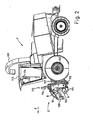
- An example designed as a forage harvester 1 multifunctional agricultural vehicle shows a multi-part device 2 according to the invention.
- the forage harvester 1 corresponds, for example, to an already commercially available forage harvester 1, which is already widely in use under the name "JAGUAR" of the applicant.
- the forage harvester 1 accommodates a device 2 according to the invention, which is designed as a so-called "pick-up".
- the device 2 comprises a total of three working or receiving units, a central unit 3 and two side units 4, 5.
- Cross augers 6, 7, 8 serve to picked crop a central feeder 9th supply.
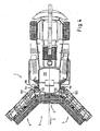
- the position of an axis of rotation 10 above an axis of rotation 11 for the revolving, only for reasons of clarity here not illustrated conveyor tines is shown in the illustration FIG. 2 good to see.
- the conveyor tines or receiving elements form part of an "actual" pick-up 100, 101, 102.
- Such pick-ups 100 to 102 generally have four rows of tines offset radially by approximately 90 ° and extending around the axis of rotation 11 turn.
- a tine control is provided which includes a mechanical cam track or the like, so that the radial alignment of the tines in the rotation about the axis of rotation 11 adjusted in an advantageous manner.
- Such a tine control or the "actual" pick-up 100, 101, 102 are already used for example in balers, loader wagons or the like accordingly. Because of this, most of the pick-up 100 to 102 can be made use of already commercially available components, such as e.g. the tines, the cover plates between the tines etc.
- the illustrated pick-up 100 to 102 of the device 2 to a novel drive, since so far in a single pick-up the drive of the tines was arranged on the outside. Although this could be realized for the two outer pick-up 100 and 102, but not for the middle pick-up 100, otherwise the distance between the edge tines of two adjacent pick-up would be 100 to 102 so large that crops in between would remain in the field.
- a novel drive 103, 104, 105 is used here for all three pick-ups 100 to 102, which is arranged within the respective working width.
- the arranged within the working width of the conveyor tines Drives 103, 104, 105 are merely exemplarily arranged approximately in the middle of the respective pick-up 100 to 102.
- the crop not shown, for example, by means of the pick-up 100, 101, 102 added and raised with the aid of a blank holder 106, 107, 108 in an advantageous manner to the transverse screw conveyors 6 to 8 or transported.
- the hold-downs 106 to 108 are formed such that they are pivotable about an axis of rotation and thus variable in height and also by means of two rollers with not shown paddles or the like advantageously support the transport of the crop to the cross auger 6 to 8 and ensure.
- FIG. 1 It is clear that the crop is conveyed by the rotation of the transverse screw conveyors 6 to 8 about the axis of rotation 10 in a correspondingly advantageous direction in the middle of the forage harvester 1 and the device 2, wherein an optionally provided indentation 9 the crop contrary to the direction of travel F inside conveyed by the forage harvester 1 or even partially pressed even with very large Erntegutmengen.
- the forage harvester 1 has a chopping device (not shown in detail) which comminutes or chops the crop and conveys it, for example, to a corresponding transport vehicle by means of a discharge chute 109.
- a chopping device not shown in detail
- the vehicle or the forage harvester 1 can be used as a multifunctional forage harvester 1, which is already in widespread use at present, such as, for example, the forage harvester "JAGUAR" of the applicant.
- the pick-up can be 100 to 102 arranged advantageously on a rotatable rocker or the like, so that the individual pick-up 100 to 102 can be adjusted by means of the respective rocker to uneven ground during the working phase.
- each unit 3, 4, 5 and two separately swingable or variable-height pick-up or more can be used to optionally further improve the ground adjustment.
- FIG. 2 illustrates how close the device 2 and thus the common center of gravity of all units 3 to 5 on the forage harvester 1 or on the front wheel axle 112 is arranged. This results in a particularly compact and agile vehicle unit during work. In addition, the axle load on the front wheels during work is minimized. In such a vehicle, as shown, the driver sits in his cabin 113 immediately near the Erntegutagestelle or directly above the device 2 so that it can see the relevant work area of the device 2 despite the very large working width extremely good.
- an edge detection and / or an obstacle detection system and / or a metal detector and / or a location system, in particular a GPS system, etc., or the like to provide for the protection of the components or to automate and increase the efficiency of Ernteguting.
- the device 2 has a lifting mechanism or a lift 115 for the central unit 3.
- the lift 115 advantageously has two guide rails 116, along which the central unit 3 is arranged substantially rectilinearly adjustable.
- two advantageously synchronized lifting units in particular hydraulic cylinders, are provided which enable the adjustment of the central unit 3 along the guide rails 116.
- guide rails 116 are in the Essentially about approximately U-shaped guide rails 116, which realize above all a roller bearing guide, but also partly a sliding guide of the central unit 3. Basically, a synchronization in the use of two lifting systems or hydraulic cylinders, especially in such a large or heavy units 3 to 5 of great advantage. This can be realized for example by means of a hydraulic and / or an electronic coupling. With the use of hydraulic cylinders or the like they can be arranged within the guide rails 116, which allows a particularly space-saving design.
- the forage harvester 1 has a rocker 117 rotatable about a rotation axis, to which the device 2 is coupled in an advantageous manner.
- the rocker 117 is already present in commercial field hoppers 1 as in the already mentioned "JAGUAR" of the applicant and has in addition to hydraulic connection options and at least one coupling point for transmitting rotational energy, a so-called PTO or the like.
- PTO By means of this PTO, in particular the drive of the pick-up 100 to 102 and the transverse screw conveyors 6 to 8 including the intake 9 is realized.
- the drive not shown on a length change.
- a dog clutch or the like which is disengaged in the transport position, and / or a telescopic drive shaft.
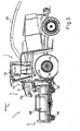
- FIG. 3 becomes clear.
- further components of the device 2 become visible. These include a variable length drive shaft 118 and a disengaged jaw clutch 119. Furthermore, feed rollers 120 of the forage harvester 1 are visible to the crop.
- a pivot axis 121 is visible, around which the entire device 2 can pivot to compensate for unevenness of the ground relative to the vehicle. For example, a pendulum motion of a total of about 10 ° is realized.
- FIG. 3 is the central unit raised to the maximum point, so that subsequently the two side units 4 and 5 can each be pivoted about a pivot axis 122.
- advantageous drives or hydraulic cylinders 123 are provided.
- the two side units 4 and 5 pivot substantially until they are aligned approximately in the direction of travel. Subsequently, the central unit can be lowered slightly, if necessary, until they are preferably placed on the two side parts 4 and 5 by means of corresponding stop elements. As a result, a particularly compact and stable arrangement of the large and heavy units 3 to 5 is realized in the transport phase.
- An interlocking bar or a locking element arranged on the two side units 4 and 5 is provided on the front side, so that unintentional pivoting of the two side units 4 or 5 during travel is reliably prevented. This increases the safety in the transport phase.
- a standardized lift 115 can be used for a wide variety of implements, so that the number of pieces is increased during production for corresponding lifts 115, which has an economically favorable effect.
- a corresponding lift 115 can be used not only for pick-up 100 to 102 or mowers, but also for maize harvesting equipment, in particular for harvesting the maize plants for silage purposes or for harvesting the corn kernels by means of appropriate threshing devices. It is even conceivable that the device 2 has at least two rotary rakes for crop cutting or swathing preferably with simultaneous picking up of the crop.
- the forage harvester 1 according to the FIGS. 1 to 6 can be brought into an intermediate position of the working units 3, 4, 5, as exemplified by a second forage harvester 1 with Mähvorsatz 2 in FIG. 7 is shown.
- the mowing attachment 2 here comprises three mowers 3, 4, 5, which have a plurality of working members 200 or mowing rotors 200.
- the mowing rotors 200 are designed such that in the working position (see. FIG. 9 ) Two adjacent mowing rotors 200 have overlapping gyroscopes. This also applies to the adjacent mowing rotors 200 of two adjacent working units 3, 4, 5 and mowers 3, 4, 5. Accordingly, a continuous working width of the mowing rotors 200 is realized, which relates to the direction of travel F are arranged at the same height or in alignment with each other or perpendicular to the direction of travel F. Accordingly, it is effectively prevented that crop remains even when cornering with very tight radii between the mower 3, 4, 5 or work units 3, 4, 5.
- FIG. 8 is, inter alia, a schematic enlargement of two coupling units 201, 202 for auxiliary organs 6, 7, 8, 203, 204, 205 and transverse conveyors 6, 7, 8 and paddle 203, 204, 205 shown in the pivoted-back intermediate position.
- the auxiliary organs 6, 7, 8, 203, 204, 205 and transverse conveyors 6, 7, 8 and paddles 203, 204, 205 are disengaged in this intermediate position, so that the average working unit 3 is advantageously vertical is adjustable.
- the two outer working units 4, 5 and mowers 4, 5 are pivoted forward, so that the two clutches 201, 202 engage and an advantageous energy transfer, in particular the front side, between the working units 3, 4, 5 is ensured ,
- the two clutches 201, 202 are preferably mechanically coded and / or at least partially resilient in the longitudinal axis, so that when the drive for the auxiliary organs 6, 7, 8, 203, 204, 205 or transverse conveyors 6, 7, 8 and paddle 203, 204, 205 engage the clutches in a predetermined or defined position to each other. This ensures that the auxiliary organs 6, 7, 8, 203, 204, 205 and transverse conveyors 6, 7, 8 and paddle 203, 204, 205 of the various working units 3, 4, 5 are defined at work to each other or rotate ,
- the drive of the auxiliary organs 6, 7, 8, 203, 204, 205 and transverse conveyors 6, 7, 8 and paddle 203, 204, 205 is provided from one side of the device 2 and in Advantageously, by means of the couplings 201, 202 of unit 3, 4, 5 forwarded to unit 3, 4, 5.
- the drive of the working members 200 and mowing rotors should always remain engaged, since here the mower 3, 4, 5, an intermediate gear 208, 209, 210 preferably having a translation.
- the translation is advantageous to realize the highest possible speed of the mowing rotors 200.
- the translation requires disengaging the drive of the mowing rotors 200, e.g. for the transport position, can not realize an encoding of a corresponding coupling in an advantageous manner.
- the position of the adjacent Mäh Vietnameseel 200 two adjacent mowers 3, 4, 5 may not change to maintain a defined position, in particular offset by 90 ° position this.
- guards 211, 212, 213 are folded down in the transport position to allow the compact position of the units 3, 4, 5 and to improve the visibility for the driver.
- the protective straps 211, 212, 213 are folded up, so that protective mats, not shown, are arranged in front of the mowing rotors 200, as is currently required.
Abstract
Description
Die Erfindung betrifft eine Vorrichtung zum Bearbeiten eines landwirtschaftlichen Feldes und/oder von auf dem Feld angeordneten Pflanzen, insbesondere zur frontseitigen Anordnung an einem landwirtschaftlichen Fahrzeug, mit einer ersten, wenigstens ein erstes Arbeitsorgan aufweisenden Arbeitseinheit und einer zweiten, wenigstens ein zweites Arbeitsorgan aufweisendes Arbeitseinheit nach dem Oberbegriff des Anspruchs 1.The invention relates to a device for processing an agricultural field and / or plants arranged on the field, in particular for the frontal arrangement on an agricultural vehicle, having a first, at least one first working member having a working unit and a second, at least one second working member exhibiting work unit the preamble of
Um die Bearbeitung landwirtschaftlicher Flächen möglichst ökonomisch und zügig durchzuführen, ist es wünschenswerte dass die Arbeitsgeräte eine möglichst große Arbeitsbreite aufweisen. Dementsprechend werden in den letzten Jahren die Arbeitsbreiten von entsprechenden Arbeitsgeräten bzw. Erntevorsätzen oder dergleichen immer größer.To perform the processing of agricultural land as economically and quickly as possible, it is desirable that the implements have the widest possible working width. Accordingly, in recent years, the working widths of respective implements or harvesting attachments or the like are becoming ever greater.
Allerdings ist für ein Straßenverkehrsmittel, wie es landwirtschaftliche Fahrzeuge auch sind, nur eine begrenzte Breite während des Straßenbetriebs z.B. zum Erreichen verstreut liegender Felder erlaubt, so dass das Arbeitsfahrzeug während des Straßenbetriebs diese zulässige Breite nicht überschreiten darf. Es ist deshalb notwendig, dass Arbeitseinheiten von einer Arbeitsstellung mit möglichst großer Arbeitsbreite in eine Transportsstellung gebracht werden können, die im Rahmen der zulässigen Breite für ein Straßenverkehrsmittel bleibt.However, for a road transport vehicle, such as agricultural vehicles, only a limited width is allowed during road operation, for example, to reach scattered fields, so that the work vehicle may not exceed this allowable width during road operation. It is therefore necessary that work units from a working position with as possible large working width can be brought into a transport position, which remains within the permissible width for a means of transport.
Zum Verstellen der Arbeitseinheiten zwischen einer Arbeits- und einer Transportsstellung sind bereits unterschiedlichste Systeme bzw. Techniken bekannt. Beispielsweise ist gemäß der
Weiterhin ist aus der
Nachteilig bei einem Verschwenken bzw. einer Schwinge ist jedoch, dass durch die Rotation beim Verschwenken die entsprechende Arbeitseinheit in der herabgesenkten Position zwangsweise auch eine Bewegung nach vorne aufweist. Dies führt unter anderem zu ungünstigen Belastungen und zu einer Reduzierung der Wendigkeit der gesamten Fahrzeugeinheit.A disadvantage of a pivoting or a rocker, however, is that by rotation during pivoting the corresponding working unit in the lowered position forcibly also has a forward movement. Among other things, this leads to unfavorable loads and to a reduction in maneuverability of the entire vehicle unit.
Großer Vorteil bei bisherigen, um Rotationsachsen rotierende Arbeitseinheiten ist, dass das Antriebssystem für derartig rotatorisch verstellte Arbeitseinheiten konstruktiv einfach ausgeführt werden kann, in dem beispielsweise eine Drehachse eines Kettenblatts, einer Riemenscheibe, eines Kardangelenks oder dergleichen fluchtend zur Schwenkachse der Arbeitseinheit angeordnet ist.A great advantage of previous working units rotating about axes of rotation is that the drive system for such rotationally displaced working units is structurally simple can be performed, for example, in which an axis of rotation of a chainring, a pulley, a universal joint or the like is arranged in alignment with the pivot axis of the working unit.
Darüber hinaus ist aus der
Nachteilig bei einer derartigen verstelleinheit ist jedoch, dass bei vergleichsweise hohen Arbeitseinheiten die Gesamthöhe von drei übereinander gestapelten Arbeitseinheiten so groß ist, dass bei einer frontseitigen Anordnung an einem Arbeitsfahrzeug die Sicht für den Fahrer eingeschränkt wird.The disadvantage of such an adjustment is, however, that at comparatively high work units, the total height of three stacked work units is so large that in a front-side arrangement on a work vehicle, the view is limited for the driver.
Vorteil bei dieser Art der Anordnung der Arbeitseinheiten in Arbeitsstellung auf gleicher Höhe in Fahrtrichtung betrachtet ist jedoch, die sehr kompakte Ausbildung des gesamten landwirtschaftlichen Arbeitsfahrzeugs während der Arbeit und des Transportes, was sowohl zu einer hohen Wendigkeit bzw. Kompaktheit sowie auch zu einer günstigen Anordnung des Schwerpunktes des Arbeitsgerätes und somit einer vorteilhaften Achsbelastung führt.Considered advantage in this type of arrangement of the working units in working position at the same height in the direction of travel, however, the very compact design of the entire agricultural work vehicle during work and transport, resulting in both a high maneuverability and compactness as well as a favorable arrangement of the Center of gravity of the implement and thus leads to an advantageous axle load.
Bei derartigen landwirtschaftlichen Arbeitseinheiten ist es jedoch auch von Nachteil, dass die Antriebsenergie für die Arbeitsorgane benachbarter und verstellbarer Arbeitseinheiten relativ aufwendig übertragen werden muss bzw. wie bereits kurz erwähnt auf die Schwenkachsen der Schwenkeinheiten für die Arbeitseinheiten angewiesen bzw. festgelegt sind.In such agricultural work units, however, it is also disadvantageous that the drive energy for the working organs of adjacent and adjustable work units must be relatively expensive to transfer or as already briefly mentioned rely on the pivot axes of the pivot units for the working units or fixed.
Darüber hinaus ist es gerade bei Mähwerken mit wenigstens drei in Fahrtrichtung versetzt bzw, in V-Form angeordneter Mähwerke, insbesondere Trommel- und/oder Scheibenmähwerke, von Nachteil, dass in Kurvenfahrten zwischen den Mähwerken Mähgut stehen bleiben kann. Hier wird zum Teil bereits als Abhilfe eine Querverstellung der äußeren Mähwerke mittels teleskopierbarer Träger oder dergleichen während der Kurvenfahrt realisiert. Dies ist jedoch steuerungstechnisch als auch konstruktiv sehr aufwendig.In addition, it is just at mowers with at least three offset in the direction of travel or, arranged in a V-shape mowers, especially drum and / or disc mowers, disadvantageous that can remain in cornering between the mowing crops. Here is partly already being remedied as a transverse adjustment of the outer mowers by means of telescoping carrier or the like during cornering. However, this is control technology and constructive very expensive.
Darüber hinaus ist aus der Druckschrift
Aufgabe der Erfindung ist es demgegenüber, eine Vorrichtung zum Bearbeiten eines landwirtschaftlichen Feldes und/oder von auf dem Feld angeordneten Pflanzen, insbesondere zur frontseitigen Anordnung an einem landwirtschaftlichen Fahrzeug, vorzuschlagen, die Nachteile des Stands der Technik im Wesentlichen vermeidet.The object of the invention is in contrast to propose a device for processing an agricultural field and / or arranged on the field plants, in particular for the front-side arrangement of an agricultural vehicle, which avoids the disadvantages of the prior art substantially.
Diese Aufgabe wird, ausgehend von einer Vorrichtung der einleitend genannten Art, durch die kennzeichnenden Merkmale der Anspruch 1 gelöst. Durch die in den Unteransprüchen genannten Maßnahmen sind vorteilhafte Ausführungen und Weiterbildungen der Erfindung möglich.This object is achieved on the basis of a device of the aforementioned type, by the characterizing features of
Dementsprechend zeichnet sich eine erfindungsgemäße Vorrichtung dadurch aus, dass wenigstens eine der Arbeitseinheiten in der Transportstellung in Fahrtrichtung betrachtet ein hinterer Endabschnitt und ein vorderer Endabschnitt aufweist und dass in einer Zwischenstellung in Fahrtrichtung betrachtet der hintere Endabschnitt der Arbeitseinheiten vor dem vorderen Endabschnitt angeordnet ist.Accordingly, a device according to the invention is characterized in that at least one of the working units in the transport position viewed in the direction of travel has a rear end portion and a front end portion and that viewed in an intermediate position in the direction of travel, the rear end portion of the working units is arranged in front of the front end portion.
Mit Hilfe dieser Maßnahme wird erreicht, dass die Energieübertragung zwischen den Arbeiteinheiten bzw. zwischen den Arbeits- und/oder Hilfsorganen besonders einfach realisierbar ist.With the help of this measure it is achieved that the energy transfer between the working units or between the working and / or auxiliary organs is particularly easy to implement.
Durch die Anordnung zumindest eine der Arbeitseinheiten in einer Zwischenstellung wenigstens teilweise entgegen der Fahrtrichtung bzw. wenigstens teilweise nach hinten gerichtet kann z.B. eine vorteilhafte zumindest zweiteilige Kupplungseinheit zur übertragung der Antriebsenergie für die Arbeitseinheiten bzw. Arbeits- und/oder Hilfsorgane in der Zwischenstellung außer Eingriff sein und durch Verstellen der entsprechenden Arbeitseinheit in die Arbeitsstellung in Eingriff gebracht werden.By arranging at least one of the working units in an intermediate position, at least partially directed counter to the direction of travel or at least partially towards the rear, it is possible, e.g. an advantageous at least two-part coupling unit for the transmission of drive energy for the working units or working and / or auxiliary organs in the intermediate position to be disengaged and brought into engagement by adjusting the corresponding working unit in the working position.
Die Kupplungseinheit kann beispielsweise als Klauenkupplung oder dergleichen ausgebildet werden. Durch eine Codierung oder dergleichen der Kupplungseinheit z.B. mittels vorteilhafter Ausnehmungen, Vertiefungen bzw. Nuten und/oder Erhebungen bzw. Federn oder dergleichen kann eine mechanische Codierung realisiert werden. Hiermit wird erreicht, dass die Stellung der Arbeits- und/oder Hilfsorgane der einzelnen Arbeitseinheiten definiert erfolgt bzw, immer zueinander festgelegt ist.The coupling unit may be formed, for example, as a dog clutch or the like. By coding or the like of the coupling unit e.g. By means of advantageous recesses, depressions or grooves and / or elevations or springs or the like, a mechanical coding can be realized. This ensures that the position of the working and / or auxiliary organs of the individual work units is defined or, is always fixed to each other.
Vorzugsweise ist eine Längsachse zumindest einer der Arbeitseinheiten in einer Zwischenstellung wenigstens teilweise entgegen der Fahrtrichtung angeordnet ist, wobei die Zwischenstellung zwischen Arbeits- und Transportstellung angeordnet ist.Preferably, a longitudinal axis of at least one of the working units is arranged in an intermediate position at least partially opposite to the direction of travel, wherein the intermediate position between the working and transport position is arranged.
In einer vorteilhaften Variante der Erfindung ist die Verstelleinrichtung wenigstens eine Schwenkeinheit zum Verschwenken wenigstens einer der Arbeitseinheiten um eine Schwenkachse aufweist, wobei die Schwenkeinheit insbesondere eine im Wesentlichen vertikal ausgerichteten Schwenkachse aufweist.In an advantageous variant of the invention, the adjusting device has at least one pivoting unit for pivoting at least one of the working units about a pivot axis, the pivoting unit in particular having a substantially vertically oriented pivot axis.
Beispielsweise wird die Energieübertragung zwischen den Arbeiteinheiten bzw. zwischen den Arbeits- und/oder Hilfsorganen an den Stirnseiten Arbeiteinheiten verwirklicht.For example, the energy transfer between the work units or between the work and / or Auxiliary organs on the front sides realized work units.
In einer bevorzugten Ausführungsform der Erfindung weist die Verstelleinrichtung wenigstens eine Lineareinheit zur im Wesentlichen geradlinigen Translation wenigstens einer der Arbeitseinheiten auf. Mit Hilfe einer derartig translatorisch verstellten Arbeitseinheit ist es möglich, vorzugsweise die zentrale Arbeitseinheit beispielsweise vertikal derart anzuheben, dass diese sowohl in der Arbeits- als auch in der Transportstellung sehr nahe am Arbeitsfahrzeug bzw. an dessen Achse, insbesondere Vorderachse, angeordnet ist. Hierdurch wird sowohl in Arbeits- als auch in Transportsstellung eine vorteilhafte Lage des Schwerpunkts der zentralen Arbeitseinheit realisierbar.In a preferred embodiment of the invention, the adjusting device has at least one linear unit for the substantially rectilinear translation of at least one of the working units. With the help of such a translationally displaced working unit, it is possible, for example, to raise the central working unit vertically such that it is arranged both in the working and in the transport position very close to the working vehicle or on its axis, in particular the front axle. As a result, an advantageous position of the center of gravity of the central work unit can be realized both in working and in transport position.
Darüber hinaus wird mittels einer translatorisch verstellten Arbeitseinheit gemäß der Erfindung erreicht, dass beispielsweise die weitere oder z.B. zwei äußere Arbeitseinheiten unter der in der Transportstellung oben angeordneten Arbeitseinheit positionierbar ist/sind, ohne dass die Sicht des Fahrers beim Transport beeinträchtigt wird. Entsprechend entspricht gemäß der Erfindung die Transporthöhe der erfindungsgemäßen Vorrichtung in etwa der zweifachen Höhe einer Arbeitseinheit, selbst bei der Verwendung von drei Arbeitseinheiten. Im Gegensatz hierzu wird beispielsweise gemäß der
Zur Realisierung der translatorischen Verstellung der Arbeitseinheit, ist es auch denkbar, dass beispielsweise wenigstens eine oder die (beiden) äußeren Arbeitseinheiten translatorisch verstellt werden könnten.To realize the translational adjustment of the working unit, it is also conceivable that, for example, at least one or the (two) outer working units could be translationally adjusted.
Grundsätzlich können unterschiedlichste Antriebs- und/oder Führungssysteme verwendet werden. Beispielsweise kann eine Gleit- und/oder Wälzführung und/oder Linearantriebe vorgesehen werden. Als Linearantriebe sind beispielsweise Gewindeantriebe, Linearmotoren, elektromechanische Zylinder, Ketten- oder Seilantriebe und/oder vorzugsweise Pneumatik- oder Hydraulikantriebe verwendbar.In principle, a wide variety of drive and / or guide systems can be used. For example, a Sliding and / or Wälzführung and / or linear drives are provided. As linear drives, for example threaded drives, linear motors, electromechanical cylinders, chain or cable drives and / or preferably pneumatic or hydraulic drives are used.
Vorzugsweise ist die Lineareinheit als Hubeinheit zum im Wesentlichen vertikalen Anheben wenigstens einer der Arbeitseinheiten ausgebildet. Beispielsweise könnte die Hubeinheit ein Ketten- oder Seilantrieb aufweisen. Vorzugsweise wird die Hubeinheit mit Hilfe wenigstens eines pneumatischen oder vorzugsweise hydraulischen Hubzylinders realisiert. Hydrauliksysteme mit Hydraulikzylindern sind in der Landwirtschaft bereits vielfach im Einsatz, so dass hier auf bereits vorhandene Komponenten und vor allem auch auf entsprechende Antriebs- bzw. Verbindungssysteme mit dem landwirtschaftlichen Fahrzeug zurückgegriffen werden kann.Preferably, the linear unit is designed as a lifting unit for substantially vertical lifting of at least one of the working units. For example, the lifting unit could have a chain or cable drive. Preferably, the lifting unit is realized by means of at least one pneumatic or preferably hydraulic lifting cylinder. Hydraulic systems with hydraulic cylinders are already in use in agriculture many times, so that can be used here on existing components and especially on corresponding drive or connection systems with the agricultural vehicle.
In einer besonderen Weiterbildung der Erfindung ist vor allem für die translatorisch verstellbare Arbeitseinheit ein Antriebssystem vorgesehen, das längenveränderbar ausgebildet ist. Beispielsweise sind teleskopierbare Antriebskomponenten und/oder Kupplungseinheiten denkbar, die zur Realisierung der Längenveränderung gegebenenfalls außer Eingriff gehen bzw. zwei Komponenten aufweisen, die in der Transportstellung voneinander beabstandet sind und in der Arbeitsstellung im Eingriff bzw. formschlüssig miteinander verbunden sind.In a particular embodiment of the invention, a drive system is provided above all for the translationally adjustable working unit, which is formed variable in length. For example, telescoping drive components and / or coupling units are conceivable, which possibly go out of engagement to realize the change in length or have two components which are spaced apart in the transport position and in the working position in engagement or positively connected to each other.
Vorteilhafterweise weist die Verstelleinrichtung wenigstens eine Schwenkeinheit zum Verschwenken wenigstens einer der Arbeitseinheiten um eine, insbesondere im Wesentlichen vertikal ausgerichtete Schwenkachse auf. Beispielsweise werden die zweite und/oder eine dritte Arbeitseinheit mittels einer derartigen Schwenkachse von der Arbeitsstellung in die Transportsstellung verschwenkt.Advantageously, the adjusting device has at least one pivot unit for pivoting at least one of the working units about a, in particular substantially vertically aligned pivot axis. For example, the second and / or a third working unit are pivoted by means of such a pivot axis from the working position to the transport position.
Vorzugsweise entspricht die Arbeitsbreite der ersten Arbeitseinheit im Wesentlichen deren Transportbreite. Insbesondere entspricht die Arbeits- bzw. Transportbreite der ersten Arbeitseinheit im Wesentlichen der zulässigen Transportbreite auf öffentlichen Straßen. Hiermit wird erreicht, dass die Gesamtarbeitsbreite möglichst groß wird.Preferably, the working width of the first working unit essentially corresponds to its transport width. In particular, the working or transport width of the first working unit essentially corresponds to the permissible transport width on public roads. This ensures that the total working width is as large as possible.
In einer bevorzugten variante der Erfindung sind die Arbeitseinheiten wenigstens in Arbeitsstellung im Wesentlichen auf einer Höhe bezogen auf die Fahrtrichtung angeordnet. Gerade mit Hilfe der tranlatorischen Verstellung wenigstens einer der Arbeitseinheiten, insbesondere der zentralen Arbeitseinheit, wird mit Hilfe dieser Maßnahme ermöglicht, dass der Schwerpunkt der gesamten Vorrichtung sowohl in Transportsstellung als auch in Arbeitsstellung vergleichsweise nahe am Fahrzeug bzw. an der Vorderachse des Fahrzeugs angeordnet ist. Dies führt beispielsweise zu einer vorteilhaften Reduktion der Achslast, die auf öffentlichen Straßen ebenfalls begrenzt ist. Bei besonders großen landwirtschaftlichen Fahrzeugen mit großen Arbeitsvorrichtungen wird dies zunehmend zu einem der limitierenden Faktoren. Auch auf dem Feld ist eine möglichst geringe Achslast bzw. eine gleichmäßigere Verteilung der Achslasten von Vorteil, insbesondere bezüglich der Verdichtung des Bodens.In a preferred variant of the invention, the working units are arranged at least in working position substantially at a height relative to the direction of travel. With the aid of the translational adjustment of at least one of the working units, in particular the central working unit, this measure makes it possible for the center of gravity of the entire apparatus to be arranged comparatively close to the vehicle or to the front axle of the vehicle both in the transport position and in the working position. This leads, for example, to an advantageous reduction of the axle load, which is also limited on public roads. For very large agricultural vehicles with large working devices, this is increasingly becoming one of the limiting factors. Also in the field, the lowest possible axle load or a more even distribution of the axle loads is advantageous, in particular with regard to the compaction of the soil.
Vorteilhafterweise sind in Transportstellung die zweite und/oder die dritte Arbeitseinheit innerhalb der Transportbreite der ersten Arbeitseinheit angeordnet. Hiermit wird eine besonders kompakte Ausbildung der Vorrichtung gemäß der Erfindung in Transportstellung erreicht.Advantageously, in the transport position, the second and / or the third working unit are arranged within the transport width of the first working unit. Hereby, a particularly compact design of the device according to the invention in transport position is achieved.
In einer vorteilhaften Variante der Erfindung sind in Transportsstellung die zweite und/oder die dritte Arbeitseinheit im Wesentlichen in Fahrtrichtung ausgerichtet. Es hat sich gezeigt, dass eine derartige Anordnung gerade bei vergleichsweise große Arbeitsbreiten aufweisende Arbeitseinheiten eine besonders zweckdienliche Anordnung darstellt. Dementsprechend kann eine vergleichsweise große gesamte Arbeitsbreite realisiert werden.In an advantageous variant of the invention, in the transport position, the second and / or the third working unit are aligned substantially in the direction of travel. It has been shown that such an arrangement is just at comparatively large working widths working units represents a particularly expedient arrangement. Accordingly, a comparatively large overall working width can be realized.
Vorzugsweise entspricht die Transportbreite der Vorrichtung im Wesentlichen der Breite des dafür vorgesehenen Fahrzeugs oder ist etwas kleiner als diese. Hiermit wird eine möglichst maximale Ausnützung der zulässigen Transportbreite erreicht, was entsprechend zu einer besonders großen Arbeitsbreite führt.Preferably, the transport width of the device is substantially equal to or slightly smaller than the width of the vehicle provided therefor. This maximum possible utilization of the permissible transport width is achieved, which leads to a correspondingly large working width.
Generell kann beispielsweise die translatorisch verstellte Arbeitseinheit in der Transportstellung eine Lage aufweisen, die unterhalb der maximal anhebbaren Lage dieser Arbeitseinheit ist. Beispielsweise wird die translatorisch verstellte Arbeitseinheit in einer Zwischenstellung in maximaler, angehobener Position positioniert, zumindest während die andere bzw. die anderen Arbeitseinheiten von deren Arbeitsstellung in die Transportstellung verstellt werden. Anschließend kann beispielsweise die tranlatorisch verstellte bzw. angehobene Arbeitseinheit auf die vorzugsweise darunter angeordneten Arbeitseinheiten herabgesenkt werden, bis diese sich gegebenenfalls berühren. Dies verbessert die Stabilität und Kompaktheit der Arbeitseinheiten in der Transportstellung.In general, for example, the translationally displaced working unit in the transport position can have a position which is below the maximum liftable position of this working unit. For example, the translationally displaced working unit is positioned in an intermediate position in the maximum, raised position, at least while the other or the other working units are moved from their working position into the transport position. Subsequently, for example, the translationally displaced or raised working unit can be lowered onto the working units, which are preferably arranged underneath, until they touch, if necessary. This improves the stability and compactness of the working units in the transport position.
Grundsätzlich können als Arbeitseinheiten unterschiedlichste Arbeitswerkzeuge verwendet werden. Es ist beispielweise denkbar, für einen Mähdrescher einen Mähdreschervorsatz gemäß der Erfindung auszubilden, wobei die frontseitig angeordnete Arbeitsvorrichtung, nicht wie bislang üblich bei Mähdreschern mit großer Arbeitsbreitekomplett als eine Baueinheit vom Frontbereich entfernt und als Anhänger während der Transportphase am Mähdrescher angehängt wird, sondern entsprechend geteilt, insbesondere dreigeteilt, und ein Teil translatorisch angehoben und die anderen Teile um z.B. im Wesentlichen vertikale Achsen verschwenkbar sind.Basically, a wide variety of work tools can be used as work units. It is conceivable, for example, to form a combine harvester attachment according to the invention for a combine harvester, wherein the front-mounted working device is not removed from the front as a structural unit from combine harvesters with large working width and attached as a trailer during the transport phase on the combine harvester, but divided accordingly , in particular three parts, and a part raised translational and the other parts are pivotable about, for example, substantially vertical axes.
Vorteilhafterweise sind Arbeitseinheiten als Aufnahmeeinheiten mit jeweils wenigstens einer Mehrzahl über deren Arbeitsbreite verteilter und in Arbeitsstellung um eine quer zur Fahrtrichtung ausgerichtete Drehachse umlaufender sowie voneinander beabstandeter Aufnahmeelemente zum Aufnehmen von am Boden liegendem Erntegut ausgebildet. Derartige Aufnahmeeinheiten werden in der Landwirtschaft gewöhnlich als sogenannte "Pick-Up" bezeichnet. Gemäß der Erfindung kann beispielsweise eine vorzugsweise frontseitig am Fahrzeug anordenbare Pick-Up realisiert werden, die Arbeitsbreiten aufweist, die weit über dem bislang üblichen Maß hinausgeht. Beispielsweise können Vorrichtungen gemäß der Erfindung mit Arbeitsbreiten von ca. 8 m oder mehr realisiert werden, die in der Transportstellung kompakt und mit einem nahen Schwerpunkt insbesondere frontseitig am Fahrzeug anordnenbar ist.Advantageously, working units are designed as receiving units, each having at least a plurality distributed over the working width and in working position about a rotational axis aligned transversely to the direction of rotation rotating and spaced apart receiving elements for receiving lying on the ground crop. Such receiving units are commonly referred to in agriculture as so-called "pick-up". According to the invention, for example, a preferably front on the vehicle can be arranged pick-up can be realized, which has working widths, which goes far beyond the usual extent. For example, devices according to the invention with working widths of about 8 m or more can be realized, which is compact in the transport position and can be arranged with a close center of gravity, especially on the front of the vehicle.
Alternativ können die Arbeitseinheiten auch als Mähwerke, insbesondere mit in Arbeitsstellung um im Wesentlichen vertikal ausgerichtete Drehachsen drehende Mähwerkzeuge bzw. Schneidmesser, ausgebildet werden. Vorzugsweise weisen die Mähwerke Mähwerkzeuge in Arbeitsstellung auf, wobei sich die Flugreise der zueinander benachbarten Mähwerkzeuge in der Arbeitsstellung überlappen. Derartige Scheiben- oder Trommelmähkomponenten sind in der Landwirtschaft bereits üblich, so dass auf bereits handelsübliche Komponenten zurückgegriffen werden kann. Dies führt beispielsweise zu einem besonders wirtschaftlich günstigen Mähwerk mit vorzugsweise fluchtend angeordneten Einzelmähwerken in Arbeitsstellung.Alternatively, the working units can also be designed as mowers, in particular with mowing tools or cutting knives rotating in working position about substantially vertically oriented axes of rotation. Preferably, the mowers mowing tools in working position, wherein the flight of the mutually adjacent mowing tools overlap in the working position. Such disc or Trommelmähkomponenten are already common in agriculture, so that can be used on already commercially available components. This leads, for example, to a particularly economically favorable mower with preferably aligned mowers in working position.
Weiterhin können alternativ die Arbeitseinheiten als Mäh- und Einzugseinheiten mit in Arbeitsstellung um im Wesentlichen vertikal ausgerichtete Drehachsen drehende Mäh- und Einzugswerkzeugen ausgebildet werden. Derartige Mäh- und Einzugseinheiten sind beispielsweise als sogenannte Maisvorsätze oder dergleichen verwendbar, wobei die Pflanzen einerseits abgemäht und andererseits in den Häcksler bzw. den Drescher eingezogen werden.Furthermore, alternatively, the working units as mowing and intake units with in working position to substantially vertically oriented rotary axes rotating mowing and drawing tools are formed. Such mowing and intake units can be used, for example, as so-called corn headers or the like, wherein the plants are mowed on the one hand and fed into the shredder or the thresher on the other hand.
Vorteilhafterweise ist wenigstens eine Querfördereinheit zum wenigstens teilweise quer zur Fahrtrichtung gerichteten Fördern der Pflanzen bzw. von Erntegut vorgesehen. Gerade bei Arbeitsvorrichtungen gemäß der Erfindung mit sehr großer Arbeitsbreite ist es mit Hilfe dieser Querfördereinheit möglich, die Pflanzen bzw. das Erntegut zu wenigstens einer zentralen bzw. einzigen Stelle quer zur Fahrtrichtung zu fördern, an der/den dann die Weiterverarbeitung der Pflanzen bzw. des Erntegut erfolgen kann.Advantageously, at least one transverse conveyor unit is provided for conveying the plants or crop material, at least partially directed transversely to the direction of travel. Especially with working devices according to the invention with a very large working width, it is possible with the help of this cross conveyor unit to promote the plants or the crop to at least one central or single point transverse to the direction of travel, then the further processing of the plants or the Crop can be done.
In einer bevorzugten Ausführungsform der Erfindung weist die Querfördereinheit wenigstens eine in Arbeitsstellung um eine quer zur Fahrtrichtung ausgerichtete Rotationsachse rotierende Förderschnecke auf. Es hat sich gezeigt, dass eine derartige Förderschnecke für entsprechend große Arbeitsbreiten von besonderem Vorteil ist. Alternativ hierzu sind auch Bandförderer oder dergleichen denkbar.In a preferred embodiment of the invention, the transverse conveyor unit has at least one screw conveyor rotating in working position about a rotational axis aligned transversely to the direction of travel. It has been shown that such a screw conveyor for correspondingly large working widths is of particular advantage. Alternatively, belt conveyors or the like are conceivable.
Vorzugsweise weist jede der Arbeitseinheiten eine entsprechende Querfördereinheit bzw. eine entsprechende Förderschnecke auf, die insbesondere in Fahrtrichtung betrachtet auf gleicher Höhe in der Arbeitsstellung angeordnet sind.Preferably, each of the working units has a corresponding transverse conveyor unit or a corresponding conveyor screw, which are arranged in the working position, viewed in particular in the direction of travel, at the same height.
Generell kann ein entsprechendes landwirtschaftliches Fahrzeug sowohl als Selbstfahrer oder als Zugmaschine wie Traktor etc. zum Ankoppeln der Vorrichtung gemäß der Erfindung ausgebildet werden.In general, a corresponding agricultural vehicle can be designed both as a self-propelled tractor or as a tractor such as a tractor etc. for coupling the device according to the invention.
Vorzugsweise weist ein entsprechendes landwirtschaftliches Fahrzeug eine Häckselvorrichtung zum Häckseln der Pflanzen bzw. des Ernteguts und/oder eine Dreschvorrichtung zum Dreschen der Pflanzen bzw. des Ernteguts auf. Entsprechend können Häcksler bzw. Dreschfahrzeuge realisiert werden, die eine sehr große Arbeitsbreite aufweisen und trotzdem in der Transportstellung kompakt ausgebildet sind.Preferably, a corresponding agricultural vehicle has a chopping device for chopping the plants or the crop and / or a threshing device for threshing the plants or the crop. Accordingly, shredders or threshing vehicles can be realized, which have a very large working width and are nevertheless made compact in the transport position.
Ein Ausführungsbeispiel der Erfindung ist in der Zeichnung dargestellt und wird anhand der Figuren nachfolgend näher erläutert.An embodiment of the invention is illustrated in the drawing and will be explained in more detail with reference to FIGS.
Im Einzelnen zeigt:
Figur 1- eine schematische Frontansicht eines Feldhäckslers mit dreiteiliger Aufnahmevorrichtung in Arbeitsstellung,
Figur 2- eine schematische Seitenansicht eines Feldhäckslers gemäß
Figur 1 , Figur 3- eine schematische Frontansicht des Feldhäckslers gemäß
Figur 1 in einer ersten Zwischenstellung mit gehobenem Mittelteil, - Figur 4
- eine schematische Draufsicht des Feldhäckslers gemäß
Figur 1 in einer zweiten Zwischenstellung mit gehobenem Zwischenteil und teilweise eingeschwenkten Außenteilen, Figur 5- eine schematische Seitenansicht des Feldhäckslers gemäß
Figur 1 in Transportstellung, Figur 6- eine schematische Draufsicht des Feldhäckslers gemäß
Figur 1 in Transportstellung, Figur 7- eine schematische Draufsicht eines Feldhäckslers mit drei Mähwerken in einer erfindungsgemäßen zurückgeschwenkten Zwischenstellung,
Figur 8- eine schematische perspektivische Ansicht einschließlich einer Detailvergrößerung eines Feldhäckslers gemäß
Figur 7 in der erfindungsgemäßen zurückgeschwenkten Zwischenstellung, - Figur 9
- eine schematische Draufsicht des Feldhäckslers gemäß
Figur 7 in Arbeitsstellung, Figur 10- eine schematische Frontansicht des Feldhäckslers gemäß
Figur 7 in einer zweiten Zwischenstellung mit gehobenem Zwischenteil, Figur 11- eine schematische Draufsicht des Feldhäckslers gemäß
Figur 7 in Transportstellung und - Figur 12
- eine schematische Frontansicht des Feldhäckslers gemäß
Figur 7 in Transportstellung.
- FIG. 1
- a schematic front view of a forage harvester with three-piece receiving device in working position,
- FIG. 2
- a schematic side view of a forage harvester according to
FIG. 1 . - FIG. 3
- a schematic front view of the forage harvester according to
FIG. 1 in a first intermediate position with raised middle part, - FIG. 4
- a schematic plan view of the forage harvester according to
FIG. 1 in a second intermediate position with elevated intermediate part and partially pivoted-in outer parts, - FIG. 5
- a schematic side view of the forage harvester according to
FIG. 1 in transport position, - FIG. 6
- a schematic plan view of the forage harvester according to
FIG. 1 in transport position, - FIG. 7
- FIG. 2 is a schematic top view of a forage harvester with three mowers in a pivoted back intermediate position according to the invention, FIG.
- FIG. 8
- a schematic perspective view including an enlarged detail of a forage harvester according to
FIG. 7 in the pivoted-back intermediate position according to the invention, - FIG. 9
- a schematic plan view of the forage harvester according to
FIG. 7 in working position, - FIG. 10
- a schematic front view of the forage harvester according to
FIG. 7 in a second intermediate position with raised intermediate part, - FIG. 11
- a schematic plan view of the forage harvester according to
FIG. 7 in transport position and - FIG. 12
- a schematic front view of the forage harvester according to
FIG. 7 in transport position.
Ein beispielhaft als Feldhäcksler 1 ausgebildetes multifunktionales landwirtschaftliches Fahrzeug zeigt eine mehrteilige Vorrichtung 2 gemäß der Erfindung. Der Feldhäcksler 1 entspricht beispielsweise einem bereits handelsüblichen Feldhäcksler 1, der unter der Bezeichnung "JAGUAR" der Anmelderin bereits vielfach im Einsatz ist.An example designed as a
Der Feldhäcksler 1 nimmt eine Vorrichtung 2 gemäß der Erfindung auf, die als sogenannte "Pick-Up" ausgebildet ist. Die Vorrichtung 2 umfasst insgesamt drei Arbeits- bzw. Aufnahmeeinheiten, eine zentrale Einheit 3 sowie zwei Seiteneinheiten 4, 5. Querförderschnecken 6, 7, 8 dienen dazu, aufgenommenes Erntegut einem zentralen Einzug 9 zuzuführen. Die Lage einer Drehachse 10 oberhalb einer Drehachse 11 für die umlaufenden, lediglich aus Gründen der Übersichtlichkeit hier nicht näher dargestellten Förderzinken ist in der Darstellung gemäß
Die nicht näher dargestellten Förderzinken bzw. Aufnahmeelemente sind Bestandteil einer "eigentlichen" Pick-Up 100, 101, 102. Derartige Pick-Up 100 bis 102 weisen im Allgemeinen vorzugsweise vier um ca. 90° radial versetzte Zinkenreihen auf, die sich um die Drehachse 11 drehen. Häufig ist auch eine Zinkensteuerung vorgesehen, die eine mechanische Kurvenbahn oder dergleichen umfasst, so dass sich die radiale Ausrichtung der Zinken bei der Rotation um die Drehachse 11 in vorteilhafter Weise verstellt. Eine derartige Zinkensteuerung bzw. die "eigentlichen" Pick-Up 100, 101, 102 werden bislang bereits beispielsweise bei Ballenpressen, Ladewagen oder dergleichen entsprechend eingesetzt. Aufgrund dessen kann für die Pick-Up 100 bis 102 zu einem Großteil auf bereits handelsübliche Komponenten zurückgegriffen werden, wie z.B. die Zinken, die Abdeckbleche zwischen den Zinken etc..The conveyor tines or receiving elements (not illustrated in any more detail) form part of an "actual" pick-
Allerdings weisen die dargestellten Pick-Up 100 bis 102 der Vorrichtung 2 einen neuartigen Antrieb auf, da bislang bei einer einzelnen Pick-Up der Antrieb der Zinken außenseitig angeordnet war. Dies könnte zwar für die beiden äußeren Pick-Up 100 und 102 realisiert werden, jedoch nicht für die mittlere Pick-Up 100, da ansonsten der Abstand zwischen den Randzinken zweier benachbarter Pick-Up 100 bis 102 so groß werden würde, dass dazwischen Erntegut auf dem Feld liegen bleiben würde.However, the illustrated pick-up 100 to 102 of the
Aufgrund dessen wird hier ein neuartiger Antrieb 103, 104, 105 für alle drei Pick-Up 100 bis 102 verwendet, der innerhalb der jeweiligen Arbeitsbreite angeordnet ist. Die innerhalb der Arbeitsbreite der Förderzinken angeordneten Antriebe 103, 104, 105 sind lediglich beispielhaft etwa in der Mitte der jeweiligen Pick-Up 100 bis 102 angeordnet.Because of this, a
Vor allem in
Vor allem in
Vorteilhafterweise weist der Feldhäcksler 1 eine nicht näher dargestellte Häckselvorrichtung auf, die das Erntegut zerkleinert bzw. zerhäckselt und mittels einem Auswurfschacht 109 beispielsweise auf ein entsprechendes Transportfahrzeug befördert. Hier wird deutlich, dass das Fahrzeug bzw. der Feldhäcksler 1 als bereits derzeit vielfach im Einsatz befindlicher multifunktionaler Feldhäcksler 1, wie beispielsweise der Feldhäcksler "JAGUAR" der Anmelderin, verwendbar ist.Advantageously, the
Darüber hinaus wird vor allem in
Generell können die Pick-Up 100 bis 102 in vorteilhafter Weise an einer drehbar ausgebildeten Schwinge oder dergleichen angeordnet werden, so dass die einzelnen Pick-Up 100 bis 102 mittels der jeweiligen Schwingen an Bodenunebenheiten während der Arbeitsphase angepasst werden können. Generell ist denkbar, dass auch je Einheit 3, 4, 5 auch zwei separat schwingbare bzw. höhenvariable Pick-Up oder auch mehr, verwendet werden können, um die Bodenanpassung gegebenenfalls noch weiter zu verbessern.In general, the pick-up can be 100 to 102 arranged advantageously on a rotatable rocker or the like, so that the individual pick-up 100 to 102 can be adjusted by means of the respective rocker to uneven ground during the working phase. In general, it is conceivable that each
Aus den
Grundsätzlich ist es bei derart großen Arbeitsbreiten von Vorteil, beispielsweise eine Bestandkantenerkennung und/oder ein Hinderniserkennungssystem und/oder ein Metalldetektor und/oder ein Ortungssystem, insbesondere ein GPS-System etc., oder dergleichen zum Schutz der Komponenten bzw. zur Automatisierung und Effizienzsteigerung der Erntegutaufnahme vorzusehen.In principle, it is advantageous for such large working widths, for example, an edge detection and / or an obstacle detection system and / or a metal detector and / or a location system, in particular a GPS system, etc., or the like to provide for the protection of the components or to automate and increase the efficiency of Erntegutaufnahme.
Darüber hinaus wird vor allem in
Die Verstellbarkeit der Vorrichtung 2 von der in
Gemäß der Erfindung weist die Vorrichtung 2 eine Hubmechanik bzw. einen Lift 115 für die zentrale Einheit 3 auf. Der Lift 115 weist vorteilhafterweise zwei Führungsschienen 116 auf, entlang derer die zentrale Einheit 3 im Wesentlichen geradlinig verstellbar angeordnet ist. Ohne nähere Darstellungen sind insbesondere zwei in vorteilhafter Weise synchronisierte Hubeinheiten, insbesondere Hydraulikzylinder, vorgesehen, die die Verstellung der zentralen Einheit 3 längs der Führungsschienen 116 ermöglichen. Mittels entsprechender hydraulischer Hubkomponenten kann mit bei bereits handelsüblichen Feldhäckslern 1 vorhandenen Hydraulikkupplungen die entsprechende Hebe- und/oder Senkearbeit umgesetzt werden.According to the invention, the
Bei den dargestellten Führungsschienen 116 handelt es sich im Wesentlich um etwa U-förmige Führungsschienen 116, die vor allem eine Wälzlagerführung, aber auch zum Teil eine Gleitführung der zentralen Einheit 3 realisieren. Grundsätzlich ist ein Gleichlauf bei der verwendung zweier Hubsysteme bzw. Hydraulikzylinder gerade bei derart großen bzw. schweren Einheiten 3 bis 5 von großem Vorteil. Dies kann beispielsweise mittels einer hydraulischen und/oder einer elektronischen Kopplung realisiert werden. Mit der Verwendung von Hydraulikzylindern oder dergleichen können diese innerhalb der Führungsschienen 116 angeordnet werden, was eine besonders Platz sparende Bauweise ermöglicht.In the illustrated
Im Vergleich der beiden
Um die vertikale Verstellung der zentralen Einheit 3 zu realisieren, weist der nicht näher dargestellte Antrieb eine Längenveränderung auf. Beispielsweise eine Klauenkupplung oder dergleichen, die in der Transportstellung außer Eingriff ist, und/oder eine teleskopierbare Antriebswelle.In order to realize the vertical adjustment of the
Die Verfahrensschritte um von der Arbeitsstellung gemäß
- Im Allgemeinen wird die
Schwinge 117 desFeldhäckslers 1 unmittelbar nach der Beendigung der Erntegutaufnahme angehoben, so dass diegesamte Vorrichtung 2 vom Boden abhebt, d.h. dass dieStützräder 110 bzw. dieGleitstützen 111 nicht mehr Kontakt zum Boden haben. Hierdurch werden dieFührungsschienen 116 im dargestellten Ausführungsbeispiel in nahezu vertikaler Orientierung ausgerichtet.
- In general, the
rocker 117 of theforage harvester 1 lifted immediately after the completion of Erntegutaufnahme so that theentire device 2 lifts off the ground, ie that thesupport wheels 110 and the slide supports 111 no longer have contact with the ground. As a result, theguide rails 116 are aligned in the illustrated embodiment in a nearly vertical orientation.
Anschließend wird die zentrale Einheit 3 längs der Führungsschienen 116 nach oben verstellt, wie dies vor allem in
In
Die beiden Seiteneinheiten 4 und 5 verschwenken im Wesentlichen bis diese etwa in Fahrtrichtung ausgerichtet sind. Anschließend kann die zentrale Einheit bei Bedarf etwas abgesenkt werden, bis diese vorzugsweise mittels entsprechender Anschlagelemente auf den beiden Seitenteilen 4 und 5 aufsetzen. Hierdurch wird eine besonders kompakte und stabile Anordnung der großen und schweren Einheiten 3 bis 5 in der Transportphase realisiert.The two
Darüber hinaus kann in der Transportstellung beispielsweise stirnseitig eine an den beiden Seiteneinheiten 4 und 5 angeordnete verriegelungsstange bzw. ein Verriegelungselement vorgesehen werden, so dass ein unbeabsichtigtes Aufschwenken der beiden Seiteneinheiten 4 oder 5 während der Fahrt sicher verhindert wird. Dies erhöht die Sicherheit in der Transportphase.In addition, in the transport position, for example An interlocking bar or a locking element arranged on the two
Grundsätzlich können auch andere Ausführungsvarianten als Einheiten 3 bis 5 realisiert werden. Beispielsweise kann ein standardisierter Lift 115 für unterschiedlichste Arbeitsgeräte verwendet werden, so dass die Stückzahl bei der Herstellung für entsprechender Lifte 115 vergrößert wird, was sich wirtschaftlich günstig auswirkt. Beispielsweise kann ein entsprechender Lift 115 nicht nur für Pick-Up 100 bis 102 oder Mähwerke verwendet werden, sondern auch für Maiserntegeräte, insbesondere zum Ernten der Maispflanzen für Silagezwecke oder auch zum Ernten der Maiskörner mittels entsprechender Dreschvorrichtungen. Es ist sogar denkbar, dass die Vorrichtung 2 wenigstens zwei Kreiselrechen zum Zetten von Erntegut oder zum Schwaden vorzugsweise mit gleichzeitiger Aufnahme des Erntegutes aufweist.In principle, other embodiments as
Der Feldhäcksler 1 gemäß den
Die Mähkreisel 200 sind derart ausgebildet, dass in der Arbeitsstellung (vgl.
In
Ohne nähere Darstellung sind die beiden Kupplungen 201, 202 vorzugsweise mechanisch codiert und/oder wenigstens teilweise federnd in Längsachse ausgebildet, so dass beim Beaufschlagen des Antriebs für die Hilfsorgane 6, 7, 8, 203, 204, 205 bzw. Querförderer 6, 7, 8 und Paddel 203, 204, 205 die Kupplungen in einer vorgegebenen bzw. definierten Stellung zueinander eingreifen. Hiermit wird erreicht, dass die Hilfsorgane 6, 7, 8, 203, 204, 205 bzw. Querförderer 6, 7, 8 und Paddel 203, 204, 205 der verschiedenen Arbeitseinheiten3, 4, 5 bei der Arbeit definiert zueinander stehen bzw. sich drehen.Without further illustration, the two
Vorteilhafterweise wird der Antrieb der Hilfsorgane 6, 7, 8, 203, 204, 205 bzw. Querförderer 6, 7, 8 und Paddel 203, 204, 205 von einer Seite der Vorrichtung 2 vorgesehen und in vorteilhafter Weise mittels der Kupplungen 201, 202 von Einheit 3, 4, 5 zu Einheit 3, 4, 5 weitergeleitet.Advantageously, the drive of the
Entsprechendes trifft auch z. B. auf den Antrieb der Arbeitsorgane (100, 101, 102) 200 zu. Die Mähkreisel 200 werden von einer Seite angetrieben, insbesondere der anderen Seite wie bei den Hilfsorganen 6, 7, 8, 203, 204, 205 bzw. Querförderer 6, 7, 8 und Paddel 203, 204, 205. Hierbei werden jedoch in vorteilhafter Weise längenveränderbare Antriebe vorgesehen, insbesondere teleskopierbare Antriebe 206, 207. Die teleskopierbaren Antriebe 206, 207 bzw. Teleskope 206, 207 übertragen die Antriebsenergie von Einheit 3, 4, 5 zur benachbarten Einheit 3, 4, 5. Dies ist von Vorteil, da durch das Anheben des Mittelteils 3 bzw. durch den Lift 115 eine Längenveränderung des Antriebes beim Verstellen von der Transportstellung (vgl.
Zudem sollte jedoch der Antrieb der Arbeitsorgane 200 bzw. Mähkreisel immer im Eingriff bleiben, da hier das Mähwerk 3, 4, 5 ein Zwischengetriebe 208, 209, 210 vorzugsweise mit einer Übersetzung aufweist. Die Übersetzung ist von Vorteil, um eine möglichst große Drehzahl der Mähkreisel 200 zu realisieren. Die Übersetzung bedingt jedoch, dass ein außer Eingriff bringen des Antriebs der Mähkreisel 200, z.B. für die Transportstellung, eine Codierung einer entsprechenden Kupplung nicht in vorteilhafter Weise realisieren lässt. Die Stellung der benachbarten Mähkreisel 200 zweier benachbarter Mähwerke 3, 4, 5 darf sich nicht ändern, um eine definierte Stellung, insbesondere um 90° versetzte Stellung dieser beizubehalten.In addition, however, the drive of the working
In ersten Versuchen hat sich gezeigt, dass bei einer Vorrichtung gemäß dem Oberbegriff des Anspruchs 1 ein derartiger Antrieb der Mähkreisel 200 von einer Seite, insbesondere mittels längenveränderbarer Elemente, von besonderem Vorteil ist und die oben dargelegte Aufgabe der Erfindung löst.In first experiments it has been found that in a device according to the preamble of
In den
Weiterhin ist zu erkennen, dass Schutzbügel 211, 212, 213 in der Transportstellung nach unten geklappt sind, um die kompakte Stellung der Einheiten 3, 4, 5 zu ermöglichen und die Sicht für den Fahrer zu verbessern. In der Arbeitstellung sind die Schutzbügel 211, 212, 213 hochgeklappt, so dass nicht näher dargestellte Schutzmatten vor den Mähkreiseln 200 angeordnet sind, wie dies derzeit Vorschrift ist.Furthermore, it can be seen that
Claims (23)
- Device (2) for working an agricultural field and/or plants arranged on the field, in particular for arranging on the front of an agricultural vehicle (1), with a first working unit (3, 4, 5) comprising at least one first working element (100, 101, 102, 200) and a second working unit (3, 4, 5) comprising at least one second working element (100, 101, 102, 200), wherein the working units (3, 4, 5) are arranged in working position at least partly offset laterally perpendicular to the travelling direction (F), wherein the working units (3, 4, 5) are arranged at least partly above one another in transport position, and wherein at least one adjusting device (115, 122, 123) is provided for adjusting the working units (3, 4, 5) between the working position and transport position, wherein at least one of the working units (3, 4, 5) can be adjusted from the working position into an intermediate position at least partly opposite the travelling direction (F) and vice versa, characterised in that at least one of the working units (3, 4, 5) in transport position as viewed in travelling direction (F) has a rear end section and a front end section, and in that in an intermediate position as viewed in travelling direction (F) the rear end section of the working units (3, 4, 5) is arranged in front of the front end section.
- Device according to claim 1, characterised in that a longitudinal axis of at least one of the working units (3, 4, 5) is arranged in an intermediate position at least partly opposite the travelling direction (F), wherein the intermediate position is arranged between the working and transport position.
- Device according to one of the preceding claims, characterised in that the adjusting device (115, 122, 123) comprises at least one pivot unit (122, 123) for pivoting at least one of the working units (3, 4, 5) about a pivot axis (122), wherein the pivot unit (122, 123) comprises in particular an essentially vertically aligned pivot axis.
- Device according to one of the preceding claims, characterised in that in the transport position at least one of the working units (3. 4, 5) is arranged as viewed in travelling direction (F) behind an essentially vertically aligned pivot axis of the working unit, and in that in the working position said working unit (3, 4, 5) is arranged as viewed in travelling direction (F) in front of the pivot axis of the working unit.
- Device according to one of the preceding claims, characterised in that in the transport position the longitudinal axis of at least one of the working units (3, 4, 5) is aligned essentially in travelling direction (F).
- Device according to one of the preceding claims, characterised in that the pivot angle (γ) about the pivot axis of at least one of the working units (3, 4, 5) is essentially greater than 90° and less than 170°.
- Device according to one of the preceding claims, characterised in that at least two working units pivotable about essentially vertical rotational axes (15) are provided.
- Device according to one of the preceding claims, characterised in that in the transport position the two longitudinal axes of the working units are arranged parallel next to one another.
- Device according to one of the preceding claims, characterised in that the adjusting device (115, 122, 123) comprises at least one linear unit (115) for the essentially straight translation of least one of the working units (3, 4, 5)
- Device according to one of the preceding claims, characterised in that the linear unit (115) is designed as a lifting unit (115) for essentially vertically lifting one of the working units (3, 4, 5).
- Device according to one of the preceding claims, characterised in that the working width of the first working unit (3) corresponds essentially to its transport width.
- Device according to one of the preceding claims, characterised in that in the working position on the first working unit (3) perpendicular to the travelling direction (F) at least partly offset laterally a third working unit (4, 5) comprising at least one third working element (101, 102) is arranged
- Device according to one of the preceding claims, characterised in that the working units (3, 4, 5) are arranged at least in working position essentially at a height in relation to the travelling direction (F).
- Device according to one of the preceding claims, characterised in that in transport position the second and/or the third working unit (4, 5) are aligned essentially in travelling direction (F).
- Device according to one of the preceding claims, characterised in that the transport width of the device (2) corresponds essentially to the width of the vehicle (1) provided therefor.
- Device according to one of the preceding claims, characterised in that the working units (3, 4, 5) are designed in the form of collecting units (3, 4, 5) which have respectively at least a plurality of collecting elements distributed over their working width and rotating about a rotational axis (11) aligned perpendicular to the travelling direction and spaced apart from one another for collecting the harvest lying on the ground.
- Device according to one of the preceding claims, characterised in that the working units (3, 4, 5) are in the form of mowing units.
- Device according to one of the preceding claims, characterised in that the working units (3, 4, 5) are in the form of mowing and gathering units with mowing and gathering tools rotating in working position about rotational axes aligned to be essentially vertical.
- Device according to one of the preceding claims, characterised in that at least one cross conveying unit (6, 7, 8) is provided for conveying the plants or harvest in a direction at least partly perpendicular to the travelling direction (F).
- Device according to one of the preceding claims, characterised in that the cross conveying unit (6, 7, 8) comprises at least one screw conveyor (6, 7, 8) rotating in working position about a rotational axis (10) aligned perpendicular to the travelling direction.
- Agricultural vehicle (1), characterised in that it comprises a device (2) according to one of the preceding claims.
- Agricultural vehicle (1) according to the preceding claim, characterised in that a chopping device is provided for chopping the plants or the harvest.
- Agricultural vehicle (1) according to one of the preceding claims, characterised in that a threshing device is provided for threshing the plants or the harvest.
Applications Claiming Priority (2)
| Application Number | Priority Date | Filing Date | Title |
|---|---|---|---|
| DE200610059797 DE102006059797A1 (en) | 2006-12-15 | 2006-12-15 | Device with a first and a second working unit |
| DE102007033952A DE102007033952A1 (en) | 2006-12-15 | 2007-07-19 | Agricultural device for attaching to an agricultural vehicle comprises an adjusting unit for linearly translating the working units |
Publications (2)
| Publication Number | Publication Date |
|---|---|
| EP1932415A1 EP1932415A1 (en) | 2008-06-18 |
| EP1932415B1 true EP1932415B1 (en) | 2012-03-14 |
Family
ID=39156074
Family Applications (1)
| Application Number | Title | Priority Date | Filing Date |
|---|---|---|---|
| EP07023917A Not-in-force EP1932415B1 (en) | 2006-12-15 | 2007-12-11 | Device comprising a first and a second work unit |
Country Status (2)
| Country | Link |
|---|---|
| EP (1) | EP1932415B1 (en) |
| AT (1) | ATE548907T1 (en) |
Families Citing this family (2)
| Publication number | Priority date | Publication date | Assignee | Title |
|---|---|---|---|---|
| DE102011118510A1 (en) * | 2011-11-14 | 2013-05-16 | Biso Schrattenecker Gmbh | Connecting device for an attachment of a self-propelled machine |
| US20220007577A1 (en) * | 2018-11-16 | 2022-01-13 | Cnh Industrial America Llc | Header with modular rigid frame |
Family Cites Families (8)
| Publication number | Priority date | Publication date | Assignee | Title |
|---|---|---|---|---|
| NL270385A (en) | 1961-10-18 | |||
| DE4322263C5 (en) | 1992-07-31 | 2009-04-23 | Claas Saulgau Gmbh | A method of preparing a ground vehicle traveling work vehicle with a road operation implement and implement for placement on such a work vehicle |
| DE19523255A1 (en) * | 1995-06-27 | 1997-01-02 | Claas Saulgau Gmbh | Header on agricultural machines for picking up and moving on straw crops, for example maize plants |
| DE19921957A1 (en) * | 1999-05-14 | 2000-11-16 | Claas Saulgau Gmbh | Control for agricultural work machine |
| DE20112635U1 (en) * | 2001-07-31 | 2001-11-08 | Braun Karl | Tillage implement |
| DE102004022534B4 (en) | 2004-05-05 | 2012-01-26 | Claas Saulgau Gmbh | Harvesting machine for harvesting stalk-like crops such as corn or the like |
| DE102005004211A1 (en) * | 2005-01-29 | 2006-08-10 | Maschinenfabrik Kemper Gmbh & Co. Kg | Harvesting device, in particular harvesting attachment for agricultural harvesting machines for picking up and conveying strawberries |
| DE202006019070U1 (en) * | 2006-12-15 | 2007-05-16 | Claas Saulgau Gmbh | Agricultural device for attaching to an agricultural vehicle comprises an adjusting unit for linearly translating the working units |
-
2007
- 2007-12-11 AT AT07023917T patent/ATE548907T1/en active
- 2007-12-11 EP EP07023917A patent/EP1932415B1/en not_active Not-in-force
Also Published As
| Publication number | Publication date |
|---|---|
| ATE548907T1 (en) | 2012-03-15 |
| EP1932415A1 (en) | 2008-06-18 |
Similar Documents
| Publication | Publication Date | Title |
|---|---|---|
| EP1932416B1 (en) | Device comprising a first and a second work unit | |
| EP2384612B1 (en) | Drive assembly for a harvesting attachment of a harvesting machine | |
| EP1709858B1 (en) | Harvester head for agricultural machines | |
| DE602004012495T2 (en) | Crop pickup and harvesting vehicle | |
| EP1046329B1 (en) | Agricultural vehicle, paricularly a forage harvester or combine harvester, with an additional implement attached thereon | |
| DE10302692B4 (en) | Drive system for a header of a harvester | |
| EP3272199B1 (en) | Mulching device for processing plant stumps on a field | |
| EP1287732B1 (en) | Harvester head | |
| EP1609351A1 (en) | Harvester head drive | |
| EP2145524A2 (en) | Agricultural harvester | |
| EP1093708A1 (en) | Mowing device | |
| DE102007033952A1 (en) | Agricultural device for attaching to an agricultural vehicle comprises an adjusting unit for linearly translating the working units | |
| EP3092890B1 (en) | Cutting assembly for a harvester | |
| DE202006019070U1 (en) | Agricultural device for attaching to an agricultural vehicle comprises an adjusting unit for linearly translating the working units | |
| EP1932415B1 (en) | Device comprising a first and a second work unit | |
| EP1932417B1 (en) | Device for collecting crops lying on the ground | |
| DE102007060962A1 (en) | Forage harvesting attachment for an agricultural machine, to pick up lying crops, has structured pick-up units to ensure that everything is gathered across the whole working width and especially at the ends | |
| DE202006019069U1 (en) | Device for picking up crops lying on ground has distance of outer pick-up elements of adjacent pick-up units essentially less than or equal to mean length of crop to be picked up in working position | |
| EP1932418B1 (en) | Harvesting device for collecting harvested crops from the ground | |
| DE102008040217B4 (en) | Between an operating position and a compact transport position adjustable header | |
| DE102020203474A1 (en) | Mulching device for processing plant stubble | |
| DE102013208349B4 (en) | Drive arrangement for a header of a harvesting machine | |
| DE102014200770A1 (en) | Schwadaufnehmer with warning signs | |
| BE1027108B1 (en) | Header with a mulcher | |
| EP2692218B1 (en) | Self-propelled chaff cutter |
Legal Events
| Date | Code | Title | Description |
|---|---|---|---|
| PUAI | Public reference made under article 153(3) epc to a published international application that has entered the european phase |
Free format text: ORIGINAL CODE: 0009012 |
|
| AK | Designated contracting states |
Kind code of ref document: A1 Designated state(s): AT BE BG CH CY CZ DE DK EE ES FI FR GB GR HU IE IS IT LI LT LU LV MC MT NL PL PT RO SE SI SK TR |
|
| AX | Request for extension of the european patent |
Extension state: AL BA HR MK RS |
|
| 17P | Request for examination filed |
Effective date: 20080919 |
|
| 17Q | First examination report despatched |
Effective date: 20081105 |
|
| AKX | Designation fees paid |
Designated state(s): AT BE BG CH CY CZ DE DK EE ES FI FR GB GR HU IE IS IT LI LT LU LV MC MT NL PL PT RO SE SI SK TR |
|
| GRAP | Despatch of communication of intention to grant a patent |
Free format text: ORIGINAL CODE: EPIDOSNIGR1 |
|
| GRAS | Grant fee paid |
Free format text: ORIGINAL CODE: EPIDOSNIGR3 |
|
| GRAA | (expected) grant |
Free format text: ORIGINAL CODE: 0009210 |
|
| AK | Designated contracting states |
Kind code of ref document: B1 Designated state(s): AT BE BG CH CY CZ DE DK EE ES FI FR GB GR HU IE IS IT LI LT LU LV MC MT NL PL PT RO SE SI SK TR |
|
| REG | Reference to a national code |
Ref country code: GB Ref legal event code: FG4D Free format text: NOT ENGLISH |
|
| REG | Reference to a national code |
Ref country code: CH Ref legal event code: EP Ref country code: AT Ref legal event code: REF Ref document number: 548907 Country of ref document: AT Kind code of ref document: T Effective date: 20120315 |
|
| REG | Reference to a national code |
Ref country code: IE Ref legal event code: FG4D Free format text: LANGUAGE OF EP DOCUMENT: GERMAN |
|
| REG | Reference to a national code |
Ref country code: DE Ref legal event code: R096 Ref document number: 502007009466 Country of ref document: DE Effective date: 20120510 |
|
| REG | Reference to a national code |
Ref country code: NL Ref legal event code: VDEP Effective date: 20120314 |
|
| PG25 | Lapsed in a contracting state [announced via postgrant information from national office to epo] |
Ref country code: LT Free format text: LAPSE BECAUSE OF FAILURE TO SUBMIT A TRANSLATION OF THE DESCRIPTION OR TO PAY THE FEE WITHIN THE PRESCRIBED TIME-LIMIT Effective date: 20120314 |
|
| LTIE | Lt: invalidation of european patent or patent extension |
Effective date: 20120314 |
|
| PG25 | Lapsed in a contracting state [announced via postgrant information from national office to epo] |
Ref country code: FI Free format text: LAPSE BECAUSE OF FAILURE TO SUBMIT A TRANSLATION OF THE DESCRIPTION OR TO PAY THE FEE WITHIN THE PRESCRIBED TIME-LIMIT Effective date: 20120314 Ref country code: GR Free format text: LAPSE BECAUSE OF FAILURE TO SUBMIT A TRANSLATION OF THE DESCRIPTION OR TO PAY THE FEE WITHIN THE PRESCRIBED TIME-LIMIT Effective date: 20120615 Ref country code: LV Free format text: LAPSE BECAUSE OF FAILURE TO SUBMIT A TRANSLATION OF THE DESCRIPTION OR TO PAY THE FEE WITHIN THE PRESCRIBED TIME-LIMIT Effective date: 20120314 |
|
| PG25 | Lapsed in a contracting state [announced via postgrant information from national office to epo] |
Ref country code: CY Free format text: LAPSE BECAUSE OF FAILURE TO SUBMIT A TRANSLATION OF THE DESCRIPTION OR TO PAY THE FEE WITHIN THE PRESCRIBED TIME-LIMIT Effective date: 20120314 |
|
| PG25 | Lapsed in a contracting state [announced via postgrant information from national office to epo] |
Ref country code: EE Free format text: LAPSE BECAUSE OF FAILURE TO SUBMIT A TRANSLATION OF THE DESCRIPTION OR TO PAY THE FEE WITHIN THE PRESCRIBED TIME-LIMIT Effective date: 20120314 Ref country code: SI Free format text: LAPSE BECAUSE OF FAILURE TO SUBMIT A TRANSLATION OF THE DESCRIPTION OR TO PAY THE FEE WITHIN THE PRESCRIBED TIME-LIMIT Effective date: 20120314 Ref country code: RO Free format text: LAPSE BECAUSE OF FAILURE TO SUBMIT A TRANSLATION OF THE DESCRIPTION OR TO PAY THE FEE WITHIN THE PRESCRIBED TIME-LIMIT Effective date: 20120314 Ref country code: PL Free format text: LAPSE BECAUSE OF FAILURE TO SUBMIT A TRANSLATION OF THE DESCRIPTION OR TO PAY THE FEE WITHIN THE PRESCRIBED TIME-LIMIT Effective date: 20120314 Ref country code: IS Free format text: LAPSE BECAUSE OF FAILURE TO SUBMIT A TRANSLATION OF THE DESCRIPTION OR TO PAY THE FEE WITHIN THE PRESCRIBED TIME-LIMIT Effective date: 20120714 Ref country code: CZ Free format text: LAPSE BECAUSE OF FAILURE TO SUBMIT A TRANSLATION OF THE DESCRIPTION OR TO PAY THE FEE WITHIN THE PRESCRIBED TIME-LIMIT Effective date: 20120314 Ref country code: SE Free format text: LAPSE BECAUSE OF FAILURE TO SUBMIT A TRANSLATION OF THE DESCRIPTION OR TO PAY THE FEE WITHIN THE PRESCRIBED TIME-LIMIT Effective date: 20120314 |
|
| REG | Reference to a national code |
Ref country code: HU Ref legal event code: AG4A Ref document number: E014294 Country of ref document: HU |
|
| PG25 | Lapsed in a contracting state [announced via postgrant information from national office to epo] |
Ref country code: PT Free format text: LAPSE BECAUSE OF FAILURE TO SUBMIT A TRANSLATION OF THE DESCRIPTION OR TO PAY THE FEE WITHIN THE PRESCRIBED TIME-LIMIT Effective date: 20120716 Ref country code: SK Free format text: LAPSE BECAUSE OF FAILURE TO SUBMIT A TRANSLATION OF THE DESCRIPTION OR TO PAY THE FEE WITHIN THE PRESCRIBED TIME-LIMIT Effective date: 20120314 |
|
| PLBE | No opposition filed within time limit |
Free format text: ORIGINAL CODE: 0009261 |
|
| STAA | Information on the status of an ep patent application or granted ep patent |
Free format text: STATUS: NO OPPOSITION FILED WITHIN TIME LIMIT |
|
| PG25 | Lapsed in a contracting state [announced via postgrant information from national office to epo] |
Ref country code: DK Free format text: LAPSE BECAUSE OF FAILURE TO SUBMIT A TRANSLATION OF THE DESCRIPTION OR TO PAY THE FEE WITHIN THE PRESCRIBED TIME-LIMIT Effective date: 20120314 Ref country code: NL Free format text: LAPSE BECAUSE OF FAILURE TO SUBMIT A TRANSLATION OF THE DESCRIPTION OR TO PAY THE FEE WITHIN THE PRESCRIBED TIME-LIMIT Effective date: 20120314 |
|
| 26N | No opposition filed |
Effective date: 20121217 |
|
| REG | Reference to a national code |
Ref country code: DE Ref legal event code: R097 Ref document number: 502007009466 Country of ref document: DE Effective date: 20121217 |
|
| PG25 | Lapsed in a contracting state [announced via postgrant information from national office to epo] |
Ref country code: ES Free format text: LAPSE BECAUSE OF FAILURE TO SUBMIT A TRANSLATION OF THE DESCRIPTION OR TO PAY THE FEE WITHIN THE PRESCRIBED TIME-LIMIT Effective date: 20120625 |
|
| PG25 | Lapsed in a contracting state [announced via postgrant information from national office to epo] |
Ref country code: BG Free format text: LAPSE BECAUSE OF FAILURE TO SUBMIT A TRANSLATION OF THE DESCRIPTION OR TO PAY THE FEE WITHIN THE PRESCRIBED TIME-LIMIT Effective date: 20120614 Ref country code: MC Free format text: LAPSE BECAUSE OF NON-PAYMENT OF DUE FEES Effective date: 20121231 |
|
| REG | Reference to a national code |
Ref country code: CH Ref legal event code: PL |
|
| GBPC | Gb: european patent ceased through non-payment of renewal fee |
Effective date: 20121211 |
|
| REG | Reference to a national code |
Ref country code: IE Ref legal event code: MM4A |
|
| PG25 | Lapsed in a contracting state [announced via postgrant information from national office to epo] |
Ref country code: LI Free format text: LAPSE BECAUSE OF NON-PAYMENT OF DUE FEES Effective date: 20121231 Ref country code: IE Free format text: LAPSE BECAUSE OF NON-PAYMENT OF DUE FEES Effective date: 20121211 Ref country code: CH Free format text: LAPSE BECAUSE OF NON-PAYMENT OF DUE FEES Effective date: 20121231 |
|
| PG25 | Lapsed in a contracting state [announced via postgrant information from national office to epo] |
Ref country code: MT Free format text: LAPSE BECAUSE OF FAILURE TO SUBMIT A TRANSLATION OF THE DESCRIPTION OR TO PAY THE FEE WITHIN THE PRESCRIBED TIME-LIMIT Effective date: 20120314 Ref country code: GB Free format text: LAPSE BECAUSE OF NON-PAYMENT OF DUE FEES Effective date: 20121211 |
|
| PG25 | Lapsed in a contracting state [announced via postgrant information from national office to epo] |
Ref country code: TR Free format text: LAPSE BECAUSE OF FAILURE TO SUBMIT A TRANSLATION OF THE DESCRIPTION OR TO PAY THE FEE WITHIN THE PRESCRIBED TIME-LIMIT Effective date: 20120314 |
|
| PG25 | Lapsed in a contracting state [announced via postgrant information from national office to epo] |
Ref country code: LU Free format text: LAPSE BECAUSE OF NON-PAYMENT OF DUE FEES Effective date: 20121211 |
|
| REG | Reference to a national code |
Ref country code: FR Ref legal event code: PLFP Year of fee payment: 9 |
|
| REG | Reference to a national code |
Ref country code: FR Ref legal event code: PLFP Year of fee payment: 10 |
|
| REG | Reference to a national code |
Ref country code: FR Ref legal event code: PLFP Year of fee payment: 11 |
|
| PGFP | Annual fee paid to national office [announced via postgrant information from national office to epo] |
Ref country code: HU Payment date: 20181215 Year of fee payment: 12 Ref country code: AT Payment date: 20181220 Year of fee payment: 12 |
|
| PGFP | Annual fee paid to national office [announced via postgrant information from national office to epo] |
Ref country code: FR Payment date: 20181220 Year of fee payment: 12 Ref country code: BE Payment date: 20181217 Year of fee payment: 12 |
|
| PGFP | Annual fee paid to national office [announced via postgrant information from national office to epo] |
Ref country code: IT Payment date: 20181220 Year of fee payment: 12 |
|
| PGFP | Annual fee paid to national office [announced via postgrant information from national office to epo] |
Ref country code: DE Payment date: 20191210 Year of fee payment: 13 |
|
| REG | Reference to a national code |
Ref country code: AT Ref legal event code: MM01 Ref document number: 548907 Country of ref document: AT Kind code of ref document: T Effective date: 20191211 |
|
| REG | Reference to a national code |
Ref country code: BE Ref legal event code: MM Effective date: 20191231 |
|
| PG25 | Lapsed in a contracting state [announced via postgrant information from national office to epo] |
Ref country code: IT Free format text: LAPSE BECAUSE OF NON-PAYMENT OF DUE FEES Effective date: 20191211 Ref country code: FR Free format text: LAPSE BECAUSE OF NON-PAYMENT OF DUE FEES Effective date: 20191231 |
|
| PG25 | Lapsed in a contracting state [announced via postgrant information from national office to epo] |
Ref country code: AT Free format text: LAPSE BECAUSE OF NON-PAYMENT OF DUE FEES Effective date: 20191211 Ref country code: BE Free format text: LAPSE BECAUSE OF NON-PAYMENT OF DUE FEES Effective date: 20191231 Ref country code: HU Free format text: LAPSE BECAUSE OF NON-PAYMENT OF DUE FEES Effective date: 20191212 |
|
| REG | Reference to a national code |
Ref country code: DE Ref legal event code: R119 Ref document number: 502007009466 Country of ref document: DE |
|
| PG25 | Lapsed in a contracting state [announced via postgrant information from national office to epo] |
Ref country code: DE Free format text: LAPSE BECAUSE OF NON-PAYMENT OF DUE FEES Effective date: 20210701 |
|
| P01 | Opt-out of the competence of the unified patent court (upc) registered |
Effective date: 20230511 |