EP1932415B1 - Dispositif muni d'une première et d'une seconde unité de travail - Google Patents
Dispositif muni d'une première et d'une seconde unité de travail Download PDFInfo
- Publication number
- EP1932415B1 EP1932415B1 EP07023917A EP07023917A EP1932415B1 EP 1932415 B1 EP1932415 B1 EP 1932415B1 EP 07023917 A EP07023917 A EP 07023917A EP 07023917 A EP07023917 A EP 07023917A EP 1932415 B1 EP1932415 B1 EP 1932415B1
- Authority
- EP
- European Patent Office
- Prior art keywords
- working
- units
- unit
- travelling direction
- essentially
- Prior art date
- Legal status (The legal status is an assumption and is not a legal conclusion. Google has not performed a legal analysis and makes no representation as to the accuracy of the status listed.)
- Not-in-force
Links
Images


Classifications
-
- A—HUMAN NECESSITIES
- A01—AGRICULTURE; FORESTRY; ANIMAL HUSBANDRY; HUNTING; TRAPPING; FISHING
- A01D—HARVESTING; MOWING
- A01D41/00—Combines, i.e. harvesters or mowers combined with threshing devices
- A01D41/12—Details of combines
- A01D41/14—Mowing tables
- A01D41/144—Foldable headers
-
- A—HUMAN NECESSITIES
- A01—AGRICULTURE; FORESTRY; ANIMAL HUSBANDRY; HUNTING; TRAPPING; FISHING
- A01B—SOIL WORKING IN AGRICULTURE OR FORESTRY; PARTS, DETAILS, OR ACCESSORIES OF AGRICULTURAL MACHINES OR IMPLEMENTS, IN GENERAL
- A01B73/00—Means or arrangements to facilitate transportation of agricultural machines or implements, e.g. folding frames to reduce overall width
- A01B73/02—Folding frames
- A01B73/06—Folding frames foldable about a vertical axis
- A01B73/065—Folding frames foldable about a vertical axis to a position essentially forward of the axis, in relation to the direction of travel
Definitions
- the invention relates to a device for processing an agricultural field and / or plants arranged on the field, in particular for the frontal arrangement on an agricultural vehicle, having a first, at least one first working member having a working unit and a second, at least one second working member exhibiting work unit the preamble of claim 1.
- the three mowing units, in particular cutter bar having, wherein the middle cutter bar is pivoted for the transport position about an axis of rotation and the two outer mower bars are pivoted about a vertical vertical axis inwards.
- the outer cutter bar are arranged in the transport position on the central cutter bar.
- a working device in particular a mower known, which also has three working units.
- the central mower for the transport position by means of a rocker about a transverse to the direction of travel and substantially horizontally oriented pivot axis is pivoted so far up that the two outer mowers, which in turn are pivotable about vertical axes, can be positioned below the central mower.
- a disadvantage of a pivoting or a rocker is that by rotation during pivoting the corresponding working unit in the lowered position forcibly also has a forward movement. Among other things, this leads to unfavorable loads and to a reduction in maneuverability of the entire vehicle unit.
- a great advantage of previous working units rotating about axes of rotation is that the drive system for such rotationally displaced working units is structurally simple can be performed, for example, in which an axis of rotation of a chainring, a pulley, a universal joint or the like is arranged in alignment with the pivot axis of the working unit.
- the object of the invention is in contrast to propose a device for processing an agricultural field and / or arranged on the field plants, in particular for the front-side arrangement of an agricultural vehicle, which avoids the disadvantages of the prior art substantially.
- a device is characterized in that at least one of the working units in the transport position viewed in the direction of travel has a rear end portion and a front end portion and that viewed in an intermediate position in the direction of travel, the rear end portion of the working units is arranged in front of the front end portion.
- At least one of the working units in an intermediate position, at least partially directed counter to the direction of travel or at least partially towards the rear, it is possible, e.g. an advantageous at least two-part coupling unit for the transmission of drive energy for the working units or working and / or auxiliary organs in the intermediate position to be disengaged and brought into engagement by adjusting the corresponding working unit in the working position.
- the coupling unit may be formed, for example, as a dog clutch or the like.
- coding or the like of the coupling unit e.g. By means of advantageous recesses, depressions or grooves and / or elevations or springs or the like, a mechanical coding can be realized. This ensures that the position of the working and / or auxiliary organs of the individual work units is defined or, is always fixed to each other.
- a longitudinal axis of at least one of the working units is arranged in an intermediate position at least partially opposite to the direction of travel, wherein the intermediate position between the working and transport position is arranged.
- the adjusting device has at least one pivoting unit for pivoting at least one of the working units about a pivot axis, the pivoting unit in particular having a substantially vertically oriented pivot axis.
- the energy transfer between the work units or between the work and / or Auxiliary organs on the front sides realized work units.
- the adjusting device has at least one linear unit for the substantially rectilinear translation of at least one of the working units.
- a translationally displaced working unit it is possible, for example, to raise the central working unit vertically such that it is arranged both in the working and in the transport position very close to the working vehicle or on its axis, in particular the front axle.
- an advantageous position of the center of gravity of the central work unit can be realized both in working and in transport position.
- the transport height of the device according to the invention corresponds approximately to twice the height of a working unit, even when using three working units.
- the transport height corresponds to about three times a work unit.
- a wide variety of drive and / or guide systems can be used.
- a Sliding and / or Wälz Entry and / or linear drives are provided.
- linear drives for example threaded drives, linear motors, electromechanical cylinders, chain or cable drives and / or preferably pneumatic or hydraulic drives are used.
- the linear unit is designed as a lifting unit for substantially vertical lifting of at least one of the working units.
- the lifting unit could have a chain or cable drive.
- the lifting unit is realized by means of at least one pneumatic or preferably hydraulic lifting cylinder. Hydraulic systems with hydraulic cylinders are already in use in agriculture many times, so that can be used here on existing components and especially on corresponding drive or connection systems with the agricultural vehicle.
- a drive system is provided above all for the translationally adjustable working unit, which is formed variable in length.
- the translationally adjustable working unit which is formed variable in length.
- telescoping drive components and / or coupling units are conceivable, which possibly go out of engagement to realize the change in length or have two components which are spaced apart in the transport position and in the working position in engagement or positively connected to each other.
- the adjusting device has at least one pivot unit for pivoting at least one of the working units about a, in particular substantially vertically aligned pivot axis.
- the second and / or a third working unit are pivoted by means of such a pivot axis from the working position to the transport position.
- the working width of the first working unit essentially corresponds to its transport width.
- the working or transport width of the first working unit essentially corresponds to the permissible transport width on public roads. This ensures that the total working width is as large as possible.
- the working units are arranged at least in working position substantially at a height relative to the direction of travel.
- this measure makes it possible for the center of gravity of the entire apparatus to be arranged comparatively close to the vehicle or to the front axle of the vehicle both in the transport position and in the working position. This leads, for example, to an advantageous reduction of the axle load, which is also limited on public roads. For very large agricultural vehicles with large working devices, this is increasingly becoming one of the limiting factors. Also in the field, the lowest possible axle load or a more even distribution of the axle loads is advantageous, in particular with regard to the compaction of the soil.
- the second and / or the third working unit are arranged within the transport width of the first working unit.
- a particularly compact design of the device according to the invention in transport position is achieved.
- the second and / or the third working unit are aligned substantially in the direction of travel. It has been shown that such an arrangement is just at comparatively large working widths working units represents a particularly expedient arrangement. Accordingly, a comparatively large overall working width can be realized.
- the transport width of the device is substantially equal to or slightly smaller than the width of the vehicle provided therefor. This maximum possible utilization of the permissible transport width is achieved, which leads to a correspondingly large working width.
- the translationally displaced working unit in the transport position can have a position which is below the maximum liftable position of this working unit.
- the translationally displaced working unit is positioned in an intermediate position in the maximum, raised position, at least while the other or the other working units are moved from their working position into the transport position. Subsequently, for example, the translationally displaced or raised working unit can be lowered onto the working units, which are preferably arranged underneath, until they touch, if necessary. This improves the stability and compactness of the working units in the transport position.
- a wide variety of work tools can be used as work units. It is conceivable, for example, to form a combine harvester attachment according to the invention for a combine harvester, wherein the front-mounted working device is not removed from the front as a structural unit from combine harvesters with large working width and attached as a trailer during the transport phase on the combine harvester, but divided accordingly , in particular three parts, and a part raised translational and the other parts are pivotable about, for example, substantially vertical axes.
- working units are designed as receiving units, each having at least a plurality distributed over the working width and in working position about a rotational axis aligned transversely to the direction of rotation rotating and spaced apart receiving elements for receiving lying on the ground crop.
- Such receiving units are commonly referred to in agriculture as so-called "pick-up".
- pick-up a preferably front on the vehicle can be arranged pick-up can be realized, which has working widths, which goes far beyond the usual extent.
- devices according to the invention with working widths of about 8 m or more can be realized, which is compact in the transport position and can be arranged with a close center of gravity, especially on the front of the vehicle.
- the working units can also be designed as mowers, in particular with mowing tools or cutting knives rotating in working position about substantially vertically oriented axes of rotation.
- the mowers mowing tools in working position, wherein the flight of the mutually adjacent mowing tools overlap in the working position.
- Such disc or Trommelmähkomponenten are already common in agriculture, so that can be used on already commercially available components. This leads, for example, to a particularly economically favorable mower with preferably aligned mowers in working position.
- the working units as mowing and intake units with in working position to substantially vertically oriented rotary axes rotating mowing and drawing tools are formed.
- Such mowing and intake units can be used, for example, as so-called corn headers or the like, wherein the plants are mowed on the one hand and fed into the shredder or the thresher on the other hand.
- At least one transverse conveyor unit is provided for conveying the plants or crop material, at least partially directed transversely to the direction of travel.
- this cross conveyor unit it is possible with the help of this cross conveyor unit to promote the plants or the crop to at least one central or single point transverse to the direction of travel, then the further processing of the plants or the Crop can be done.
- the transverse conveyor unit has at least one screw conveyor rotating in working position about a rotational axis aligned transversely to the direction of travel. It has been shown that such a screw conveyor for correspondingly large working widths is of particular advantage. Alternatively, belt conveyors or the like are conceivable.
- each of the working units has a corresponding transverse conveyor unit or a corresponding conveyor screw, which are arranged in the working position, viewed in particular in the direction of travel, at the same height.
- a corresponding agricultural vehicle can be designed both as a self-propelled tractor or as a tractor such as a tractor etc. for coupling the device according to the invention.
- a corresponding agricultural vehicle has a chopping device for chopping the plants or the crop and / or a threshing device for threshing the plants or the crop. Accordingly, shredders or threshing vehicles can be realized, which have a very large working width and are nevertheless made compact in the transport position.
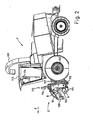
- An example designed as a forage harvester 1 multifunctional agricultural vehicle shows a multi-part device 2 according to the invention.
- the forage harvester 1 corresponds, for example, to an already commercially available forage harvester 1, which is already widely in use under the name "JAGUAR" of the applicant.
- the forage harvester 1 accommodates a device 2 according to the invention, which is designed as a so-called "pick-up".
- the device 2 comprises a total of three working or receiving units, a central unit 3 and two side units 4, 5.
- Cross augers 6, 7, 8 serve to picked crop a central feeder 9th supply.
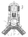
- the position of an axis of rotation 10 above an axis of rotation 11 for the revolving, only for reasons of clarity here not illustrated conveyor tines is shown in the illustration FIG. 2 good to see.
- the conveyor tines or receiving elements form part of an "actual" pick-up 100, 101, 102.
- Such pick-ups 100 to 102 generally have four rows of tines offset radially by approximately 90 ° and extending around the axis of rotation 11 turn.
- a tine control is provided which includes a mechanical cam track or the like, so that the radial alignment of the tines in the rotation about the axis of rotation 11 adjusted in an advantageous manner.
- Such a tine control or the "actual" pick-up 100, 101, 102 are already used for example in balers, loader wagons or the like accordingly. Because of this, most of the pick-up 100 to 102 can be made use of already commercially available components, such as e.g. the tines, the cover plates between the tines etc.
- the illustrated pick-up 100 to 102 of the device 2 to a novel drive, since so far in a single pick-up the drive of the tines was arranged on the outside. Although this could be realized for the two outer pick-up 100 and 102, but not for the middle pick-up 100, otherwise the distance between the edge tines of two adjacent pick-up would be 100 to 102 so large that crops in between would remain in the field.
- a novel drive 103, 104, 105 is used here for all three pick-ups 100 to 102, which is arranged within the respective working width.
- the arranged within the working width of the conveyor tines Drives 103, 104, 105 are merely exemplarily arranged approximately in the middle of the respective pick-up 100 to 102.
- the crop not shown, for example, by means of the pick-up 100, 101, 102 added and raised with the aid of a blank holder 106, 107, 108 in an advantageous manner to the transverse screw conveyors 6 to 8 or transported.
- the hold-downs 106 to 108 are formed such that they are pivotable about an axis of rotation and thus variable in height and also by means of two rollers with not shown paddles or the like advantageously support the transport of the crop to the cross auger 6 to 8 and ensure.
- FIG. 1 It is clear that the crop is conveyed by the rotation of the transverse screw conveyors 6 to 8 about the axis of rotation 10 in a correspondingly advantageous direction in the middle of the forage harvester 1 and the device 2, wherein an optionally provided indentation 9 the crop contrary to the direction of travel F inside conveyed by the forage harvester 1 or even partially pressed even with very large Erntegutmengen.
- the forage harvester 1 has a chopping device (not shown in detail) which comminutes or chops the crop and conveys it, for example, to a corresponding transport vehicle by means of a discharge chute 109.
- a chopping device not shown in detail
- the vehicle or the forage harvester 1 can be used as a multifunctional forage harvester 1, which is already in widespread use at present, such as, for example, the forage harvester "JAGUAR" of the applicant.
- the pick-up can be 100 to 102 arranged advantageously on a rotatable rocker or the like, so that the individual pick-up 100 to 102 can be adjusted by means of the respective rocker to uneven ground during the working phase.
- each unit 3, 4, 5 and two separately swingable or variable-height pick-up or more can be used to optionally further improve the ground adjustment.
- FIG. 2 illustrates how close the device 2 and thus the common center of gravity of all units 3 to 5 on the forage harvester 1 or on the front wheel axle 112 is arranged. This results in a particularly compact and agile vehicle unit during work. In addition, the axle load on the front wheels during work is minimized. In such a vehicle, as shown, the driver sits in his cabin 113 immediately near the Erntegutagestelle or directly above the device 2 so that it can see the relevant work area of the device 2 despite the very large working width extremely good.
- an edge detection and / or an obstacle detection system and / or a metal detector and / or a location system, in particular a GPS system, etc., or the like to provide for the protection of the components or to automate and increase the efficiency of Ernteguting.
- the device 2 has a lifting mechanism or a lift 115 for the central unit 3.
- the lift 115 advantageously has two guide rails 116, along which the central unit 3 is arranged substantially rectilinearly adjustable.
- two advantageously synchronized lifting units in particular hydraulic cylinders, are provided which enable the adjustment of the central unit 3 along the guide rails 116.
- guide rails 116 are in the Essentially about approximately U-shaped guide rails 116, which realize above all a roller bearing guide, but also partly a sliding guide of the central unit 3. Basically, a synchronization in the use of two lifting systems or hydraulic cylinders, especially in such a large or heavy units 3 to 5 of great advantage. This can be realized for example by means of a hydraulic and / or an electronic coupling. With the use of hydraulic cylinders or the like they can be arranged within the guide rails 116, which allows a particularly space-saving design.
- the forage harvester 1 has a rocker 117 rotatable about a rotation axis, to which the device 2 is coupled in an advantageous manner.
- the rocker 117 is already present in commercial field hoppers 1 as in the already mentioned "JAGUAR" of the applicant and has in addition to hydraulic connection options and at least one coupling point for transmitting rotational energy, a so-called PTO or the like.
- PTO By means of this PTO, in particular the drive of the pick-up 100 to 102 and the transverse screw conveyors 6 to 8 including the intake 9 is realized.
- the drive not shown on a length change.
- a dog clutch or the like which is disengaged in the transport position, and / or a telescopic drive shaft.
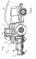
- FIG. 3 becomes clear.
- further components of the device 2 become visible. These include a variable length drive shaft 118 and a disengaged jaw clutch 119. Furthermore, feed rollers 120 of the forage harvester 1 are visible to the crop.
- a pivot axis 121 is visible, around which the entire device 2 can pivot to compensate for unevenness of the ground relative to the vehicle. For example, a pendulum motion of a total of about 10 ° is realized.
- FIG. 3 is the central unit raised to the maximum point, so that subsequently the two side units 4 and 5 can each be pivoted about a pivot axis 122.
- advantageous drives or hydraulic cylinders 123 are provided.
- the two side units 4 and 5 pivot substantially until they are aligned approximately in the direction of travel. Subsequently, the central unit can be lowered slightly, if necessary, until they are preferably placed on the two side parts 4 and 5 by means of corresponding stop elements. As a result, a particularly compact and stable arrangement of the large and heavy units 3 to 5 is realized in the transport phase.
- An interlocking bar or a locking element arranged on the two side units 4 and 5 is provided on the front side, so that unintentional pivoting of the two side units 4 or 5 during travel is reliably prevented. This increases the safety in the transport phase.
- a standardized lift 115 can be used for a wide variety of implements, so that the number of pieces is increased during production for corresponding lifts 115, which has an economically favorable effect.
- a corresponding lift 115 can be used not only for pick-up 100 to 102 or mowers, but also for maize harvesting equipment, in particular for harvesting the maize plants for silage purposes or for harvesting the corn kernels by means of appropriate threshing devices. It is even conceivable that the device 2 has at least two rotary rakes for crop cutting or swathing preferably with simultaneous picking up of the crop.
- the forage harvester 1 according to the FIGS. 1 to 6 can be brought into an intermediate position of the working units 3, 4, 5, as exemplified by a second forage harvester 1 with Mähvorsatz 2 in FIG. 7 is shown.
- the mowing attachment 2 here comprises three mowers 3, 4, 5, which have a plurality of working members 200 or mowing rotors 200.
- the mowing rotors 200 are designed such that in the working position (see. FIG. 9 ) Two adjacent mowing rotors 200 have overlapping gyroscopes. This also applies to the adjacent mowing rotors 200 of two adjacent working units 3, 4, 5 and mowers 3, 4, 5. Accordingly, a continuous working width of the mowing rotors 200 is realized, which relates to the direction of travel F are arranged at the same height or in alignment with each other or perpendicular to the direction of travel F. Accordingly, it is effectively prevented that crop remains even when cornering with very tight radii between the mower 3, 4, 5 or work units 3, 4, 5.
- FIG. 8 is, inter alia, a schematic enlargement of two coupling units 201, 202 for auxiliary organs 6, 7, 8, 203, 204, 205 and transverse conveyors 6, 7, 8 and paddle 203, 204, 205 shown in the pivoted-back intermediate position.
- the auxiliary organs 6, 7, 8, 203, 204, 205 and transverse conveyors 6, 7, 8 and paddles 203, 204, 205 are disengaged in this intermediate position, so that the average working unit 3 is advantageously vertical is adjustable.
- the two outer working units 4, 5 and mowers 4, 5 are pivoted forward, so that the two clutches 201, 202 engage and an advantageous energy transfer, in particular the front side, between the working units 3, 4, 5 is ensured ,
- the two clutches 201, 202 are preferably mechanically coded and / or at least partially resilient in the longitudinal axis, so that when the drive for the auxiliary organs 6, 7, 8, 203, 204, 205 or transverse conveyors 6, 7, 8 and paddle 203, 204, 205 engage the clutches in a predetermined or defined position to each other. This ensures that the auxiliary organs 6, 7, 8, 203, 204, 205 and transverse conveyors 6, 7, 8 and paddle 203, 204, 205 of the various working units 3, 4, 5 are defined at work to each other or rotate ,
- the drive of the auxiliary organs 6, 7, 8, 203, 204, 205 and transverse conveyors 6, 7, 8 and paddle 203, 204, 205 is provided from one side of the device 2 and in Advantageously, by means of the couplings 201, 202 of unit 3, 4, 5 forwarded to unit 3, 4, 5.
- the drive of the working members 200 and mowing rotors should always remain engaged, since here the mower 3, 4, 5, an intermediate gear 208, 209, 210 preferably having a translation.
- the translation is advantageous to realize the highest possible speed of the mowing rotors 200.
- the translation requires disengaging the drive of the mowing rotors 200, e.g. for the transport position, can not realize an encoding of a corresponding coupling in an advantageous manner.
- the position of the adjacent Mäh Vietnameseel 200 two adjacent mowers 3, 4, 5 may not change to maintain a defined position, in particular offset by 90 ° position this.
- guards 211, 212, 213 are folded down in the transport position to allow the compact position of the units 3, 4, 5 and to improve the visibility for the driver.
- the protective straps 211, 212, 213 are folded up, so that protective mats, not shown, are arranged in front of the mowing rotors 200, as is currently required.
Claims (23)
- Dispositif (2) pour le travail d'un champ agricole et/ou de plantes sur un champ notamment pour l'installation frontale sur un véhicule agricole (1) comportant :une première unité de travail (3, 4, 5) ayant au moins un premier organe de travail (100, 101, 102, 200) et une seconde unité de travail (3, 4, 5) ayant au moins un second organe de travail (100, 101, 102, 200),* les unités de travail (3, 4, 5) étant installées en position travail, transversalement par rapport à la direction de déplacement (F), en étant au moins partiellement décalées latéralement les unes par rapport aux autres,* les unités de travail (3, 4, 5) étant installées au moins en partie l'une au-dessus de l'autre en position de transport, et* au moins une installation de déplacement (115, 122, 123) est prévue pour déplacer les unités de travail (3, 4, 5) entre la position de travail et la position de transport,* au moins une des unités de travail (3, 4, 5) pouvant être déplacée de la position travail à une position intermédiaire au moins partiellement dans le sens contraire de la direction de déplacement (F) et inversement,dispositif caractérisé en ce qu'au moins l'une des unités de travail (3, 4, 5), en position de transport, vue dans la direction de déplacement (F) a un segment d'extrémité arrière et un segment d'extrémité avant,- et dans une position intermédiaire vue suivant la direction de déplacement (F), le segment d'extrémité arrière a des unités de travail (3, 4, 5) devant le segment d'extrémité avant.
- Dispositif selon la revendication 1,
caractérisé en ce que
dans une position intermédiaire, un axe longitudinal d'au moins l'une des unités de travail (3, 4, 5) est au moins dirigé en partie dans la direction opposée à la direction de déplacement (F),* la position intermédiaire étant située entre la position de travail et la position de transport. - Dispositif selon l'une des revendications précédentes,
caractérisé en ce que
l'installation de déplacement (115, 122, 123) comporte au moins une unité de basculement (122, 123) pour basculer au moins l'une des unités de travail (3, 4, 5) autour d'un axe de basculement (122),* l'unité de basculement (122, 123) ayant notamment un axe de basculement pratiquement verticale. - Dispositif selon l'une des revendications précédentes,
caractérisé en ce que dans la position de transport, au moins l'une des unités de travail (3, 4, 5) vue dans la direction de déplacement (F) est derrière un axe de basculement de l'unité de travail pratiquement vertical, et- dans la position de travail, cette unité de travail (3, 4, 5) vue dans la direction de déplacement (F) se trouve devant l'axe de basculement de l'unité de travail. - Dispositif selon l'une des revendications précédentes,
caractérisé en ce que
en position de transport, l'axe longitudinal d'au moins l'une des unités de travail (3, 4, 5) est alignée pratiquement dans la direction de déplacement (F). - Dispositif selon l'une des revendications précédentes,
caractérisé en ce que
l'angle de basculement (Y) autour de l'axe de basculement d'au moins l'une des unités de travail (3, 4, 5) est pratiquement supérieur à 90° et inférieur à 170°. - Dispositif selon l'une des revendications précédentes,
caractérisé par
au moins deux unités de travail basculant autour d'axes de rotation (15) essentiellement verticaux. - Dispositif selon l'une des revendications précédentes,
caractérisé en ce qu'
en position de transport, les deux axes longitudinaux des unités de travail sont juxtaposés parallèlement. - Dispositif selon l'une des revendications précédentes,
caractérisé en ce que l'installation d'actionnement (115, 122, 123) comporte au moins une unité linéaire (115) pour une translation pratiquement rectiligne d'au moins l'une des unités de travail (3, 4, 5). - Dispositif selon l'une des revendications précédentes,
caractérisant ce que
l'unité linéaire (115) est une unité de soulèvement (115) pour soulever pratiquement verticalement l'une des deux unités de travail (3, 4, 5). - Dispositif selon l'une des revendications précédentes,
caractérisé en ce que la largeur de travail de la première unité de travail (3) correspond essentiellement à sa largeur de transport. - Dispositif selon l'une quelconque des revendications précédentes,
caractérisé en ce qu'
en position de travail sur la première unité de travail (3), transversalement à la direction de déplacement (F), latéralement, décalée en partie, il y a une troisième unité de travail (4, 5) ayant au moins un troisième organe de travail (101, 102). - Dispositif selon l'une des revendications précédentes,
caractérisé en ce qu'
au moins en position de travail, les unités de travail (3, 4, 5) sont installées principalement à une hauteur dans la direction de déplacement (F). - Dispositif selon l'une des revendications précédentes,
caractérisé en ce qu'
en position de transport, la seconde et/ou la troisième unité de travail (4, 5) sont alignées essentiellement dans la direction de déplacement (F). - Dispositif selon l'une des revendications précédentes,
caractérisé en ce que
la largeur de transport du dispositif (2) correspond pour l'essentiel à la largeur du véhicule (1) pour lequel le dispositif est prévu. - Dispositif selon l'une des revendications précédentes,
caractérisé en ce que
les unités de travail (3, 4, 5) sont réalisées sous la forme d'unités de collecte (3, 4, 5) avec chaque fois au moins un ensemble d'éléments de collecte répartis sur leur largeur de travail et en position de travail, tournant autour d'un axe de rotation (11) aligné transversalement la direction de déplacement et des éléments de collecte écartés les uns des autres pour prendre les produits de récolte sur le sol. - Dispositif selon l'une des revendications précédentes,
caractérisé en ce que
les unités de travail (3, 4, 5) sont des unités de fauche. - Dispositif selon l'une des revendications précédentes,
caractérisé en ce que
les unités de travail (3, 4, 5) sont réalisées sous la forme d'unités de fauche et de collecte avec des outils de fauche et de collecte dont les axes de rotation alignés essentiellement verticalement en position de travail. - Dispositif selon l'une des revendications précédentes,
caractérisé par
au moins une unité de transfert transversal (6, 7, 8) pour transférer des plantes ou au moins des produits de récoltes au moins en partie transversalement à la direction de déplacement (F). - Dispositif selon l'une des revendications précédentes,
caractérisé en ce que
l'unité de transfert transversal (6, 7, 8) comporte au moins une vis transport (6, 7, 8) tournant autour d'un axe de rotation (10) dirigé en position de travail, transversalement à la direction de déplacement. - Véhicule à usage agricole (1),
caractérisé en ce qu'
il comporte un dispositif (2) selon l'une des revendications précédentes. - Véhicule à usage agricole (1) selon la revendication précédente, caractérisé en ce qu'
il comporte un dispositif hacheur pour hacher les plantes ou les produits de récolte. - Véhicule à usage agricole (1) selon l'une des revendications précédentes,
caractérisé par
un dispositif batteur pour battre les plantes ou les produits de récolte.
Applications Claiming Priority (2)
| Application Number | Priority Date | Filing Date | Title |
|---|---|---|---|
| DE200610059797 DE102006059797A1 (de) | 2006-12-15 | 2006-12-15 | Vorrichtung mit einer ersten und einer zweiten Arbeitseinheit |
| DE102007033952A DE102007033952A1 (de) | 2006-12-15 | 2007-07-19 | Vorrichtung mit einer ersten und zweiten Arbeitseinheit |
Publications (2)
| Publication Number | Publication Date |
|---|---|
| EP1932415A1 EP1932415A1 (fr) | 2008-06-18 |
| EP1932415B1 true EP1932415B1 (fr) | 2012-03-14 |
Family
ID=39156074
Family Applications (1)
| Application Number | Title | Priority Date | Filing Date |
|---|---|---|---|
| EP07023917A Not-in-force EP1932415B1 (fr) | 2006-12-15 | 2007-12-11 | Dispositif muni d'une première et d'une seconde unité de travail |
Country Status (2)
| Country | Link |
|---|---|
| EP (1) | EP1932415B1 (fr) |
| AT (1) | ATE548907T1 (fr) |
Families Citing this family (2)
| Publication number | Priority date | Publication date | Assignee | Title |
|---|---|---|---|---|
| DE102011118510A1 (de) * | 2011-11-14 | 2013-05-16 | Biso Schrattenecker Gmbh | Anschlußvorrichtung für ein Vorsatzgerät einer selbstfahrenden Arbeitsmaschine |
| WO2020101871A1 (fr) * | 2018-11-16 | 2020-05-22 | Cnh Industrial America Llc | Collecteur à cadre rigide modulaire |
Family Cites Families (8)
| Publication number | Priority date | Publication date | Assignee | Title |
|---|---|---|---|---|
| NL270385A (fr) | 1961-10-18 | |||
| DE4322263C5 (de) | 1992-07-31 | 2009-04-23 | Claas Saulgau Gmbh | Verfahren zur Vorbereitung eines auf einer Bodenfläche fahrenden Arbeitsfahrzeuges mit einem Arbeitsgerät für den Straßenbetrieb und Arbeitsgerät zur Anordnung an einem solchen Arbeitsfahrzeug |
| DE19523255A1 (de) * | 1995-06-27 | 1997-01-02 | Claas Saulgau Gmbh | Erntevorsatz an landwirtschaftlichen Arbeitsmaschinen zum Aufnehmen und Weiterführen von Halmfrüchten, beispielsweise Maispflanzen |
| DE19921957A1 (de) * | 1999-05-14 | 2000-11-16 | Claas Saulgau Gmbh | Steuerung für landwirtschaftliche Arbeitsmaschine |
| DE20112635U1 (de) * | 2001-07-31 | 2001-11-08 | Braun Karl | Bodenbearbeitungsgerät |
| DE102004022534B4 (de) | 2004-05-05 | 2012-01-26 | Claas Saulgau Gmbh | Erntemaschine zum Ernten von stängelartigem Erntegut wie Mais oder dergleichen |
| DE102005004211A1 (de) * | 2005-01-29 | 2006-08-10 | Maschinenfabrik Kemper Gmbh & Co. Kg | Erntegerät, insbesondere Erntevorsatz für landwirtschaftliche Erntemaschinen zum Aufnehmen und Weiterfördern von Halmfrüchten |
| DE202006019070U1 (de) * | 2006-12-15 | 2007-05-16 | Claas Saulgau Gmbh | Vorrichtung mit einer ersten und einer zweiten Arbeitseinheit |
-
2007
- 2007-12-11 EP EP07023917A patent/EP1932415B1/fr not_active Not-in-force
- 2007-12-11 AT AT07023917T patent/ATE548907T1/de active
Also Published As
| Publication number | Publication date |
|---|---|
| ATE548907T1 (de) | 2012-03-15 |
| EP1932415A1 (fr) | 2008-06-18 |
Similar Documents
| Publication | Publication Date | Title |
|---|---|---|
| EP1932416B1 (fr) | Dispositif muni d'une première et d'une seconde unité de travail | |
| EP2384612B1 (fr) | Agencement d'entraînement pour un accessoire de récolte d'une moissonneuse | |
| EP1709858B1 (fr) | Tête de récolte pour machines agricoles | |
| DE602004012495T2 (de) | Erntegutaufnahmevorrichtung und Erntefahrzeug | |
| EP1046329B1 (fr) | Vehicule agricole,en particulier une ramasseuse-hacheuse ou moissonneuse-batteuse, avec un outil additionel porté par le vehicule | |
| DE10302692B4 (de) | Antriebssystem für einen Erntevorsatz einer Erntemaschine | |
| EP3272199B1 (fr) | Broyeur destiné au traitement de résidus de cultures dans un champ | |
| EP1287732B1 (fr) | Tête de récolte | |
| EP1609351A1 (fr) | Entraínement d'une tête de récolte | |
| EP2145524A2 (fr) | Moissonneuse agricole | |
| EP1093708A1 (fr) | Dispositif faucheur | |
| DE102007033952A1 (de) | Vorrichtung mit einer ersten und zweiten Arbeitseinheit | |
| EP3092890B1 (fr) | Barre de coupe de moissonneuse | |
| DE202006019070U1 (de) | Vorrichtung mit einer ersten und einer zweiten Arbeitseinheit | |
| EP1932415B1 (fr) | Dispositif muni d'une première et d'une seconde unité de travail | |
| EP1932417B1 (fr) | Dispositif de saisie de récolte au sol | |
| DE102007060962A1 (de) | Erntevorsatzvorrichtung zum Aufnehmen von am Boden liegendem Erntegut | |
| DE202006019069U1 (de) | Vorrichtung zur Aufnahme von am Boden liegendem Erntegut | |
| EP1932418B1 (fr) | Dispositif accessoire de récolte destiné à ramasser les récoltes au sol | |
| DE102008040217B4 (de) | Zwischen einer Betriebsstellung und einer kompakten Transportstellung verstellbarer Erntevorsatz | |
| DE102020203474A1 (de) | Mulchgerät zur Bearbeitung von Pflanzenstoppeln | |
| DE102013208349B4 (de) | Antriebsanordnung für einen Erntevorsatz einer Erntemaschine | |
| DE102014200770A1 (de) | Schwadaufnehmer mit Warntafeln | |
| BE1027108B1 (de) | Erntevorsatz mit einem Mulchgerät | |
| EP2692218B1 (fr) | Ramasseuse-hacheuse automotrice |
Legal Events
| Date | Code | Title | Description |
|---|---|---|---|
| PUAI | Public reference made under article 153(3) epc to a published international application that has entered the european phase |
Free format text: ORIGINAL CODE: 0009012 |
|
| AK | Designated contracting states |
Kind code of ref document: A1 Designated state(s): AT BE BG CH CY CZ DE DK EE ES FI FR GB GR HU IE IS IT LI LT LU LV MC MT NL PL PT RO SE SI SK TR |
|
| AX | Request for extension of the european patent |
Extension state: AL BA HR MK RS |
|
| 17P | Request for examination filed |
Effective date: 20080919 |
|
| 17Q | First examination report despatched |
Effective date: 20081105 |
|
| AKX | Designation fees paid |
Designated state(s): AT BE BG CH CY CZ DE DK EE ES FI FR GB GR HU IE IS IT LI LT LU LV MC MT NL PL PT RO SE SI SK TR |
|
| GRAP | Despatch of communication of intention to grant a patent |
Free format text: ORIGINAL CODE: EPIDOSNIGR1 |
|
| GRAS | Grant fee paid |
Free format text: ORIGINAL CODE: EPIDOSNIGR3 |
|
| GRAA | (expected) grant |
Free format text: ORIGINAL CODE: 0009210 |
|
| AK | Designated contracting states |
Kind code of ref document: B1 Designated state(s): AT BE BG CH CY CZ DE DK EE ES FI FR GB GR HU IE IS IT LI LT LU LV MC MT NL PL PT RO SE SI SK TR |
|
| REG | Reference to a national code |
Ref country code: GB Ref legal event code: FG4D Free format text: NOT ENGLISH |
|
| REG | Reference to a national code |
Ref country code: CH Ref legal event code: EP Ref country code: AT Ref legal event code: REF Ref document number: 548907 Country of ref document: AT Kind code of ref document: T Effective date: 20120315 |
|
| REG | Reference to a national code |
Ref country code: IE Ref legal event code: FG4D Free format text: LANGUAGE OF EP DOCUMENT: GERMAN |
|
| REG | Reference to a national code |
Ref country code: DE Ref legal event code: R096 Ref document number: 502007009466 Country of ref document: DE Effective date: 20120510 |
|
| REG | Reference to a national code |
Ref country code: NL Ref legal event code: VDEP Effective date: 20120314 |
|
| PG25 | Lapsed in a contracting state [announced via postgrant information from national office to epo] |
Ref country code: LT Free format text: LAPSE BECAUSE OF FAILURE TO SUBMIT A TRANSLATION OF THE DESCRIPTION OR TO PAY THE FEE WITHIN THE PRESCRIBED TIME-LIMIT Effective date: 20120314 |
|
| LTIE | Lt: invalidation of european patent or patent extension |
Effective date: 20120314 |
|
| PG25 | Lapsed in a contracting state [announced via postgrant information from national office to epo] |
Ref country code: FI Free format text: LAPSE BECAUSE OF FAILURE TO SUBMIT A TRANSLATION OF THE DESCRIPTION OR TO PAY THE FEE WITHIN THE PRESCRIBED TIME-LIMIT Effective date: 20120314 Ref country code: GR Free format text: LAPSE BECAUSE OF FAILURE TO SUBMIT A TRANSLATION OF THE DESCRIPTION OR TO PAY THE FEE WITHIN THE PRESCRIBED TIME-LIMIT Effective date: 20120615 Ref country code: LV Free format text: LAPSE BECAUSE OF FAILURE TO SUBMIT A TRANSLATION OF THE DESCRIPTION OR TO PAY THE FEE WITHIN THE PRESCRIBED TIME-LIMIT Effective date: 20120314 |
|
| PG25 | Lapsed in a contracting state [announced via postgrant information from national office to epo] |
Ref country code: CY Free format text: LAPSE BECAUSE OF FAILURE TO SUBMIT A TRANSLATION OF THE DESCRIPTION OR TO PAY THE FEE WITHIN THE PRESCRIBED TIME-LIMIT Effective date: 20120314 |
|
| PG25 | Lapsed in a contracting state [announced via postgrant information from national office to epo] |
Ref country code: EE Free format text: LAPSE BECAUSE OF FAILURE TO SUBMIT A TRANSLATION OF THE DESCRIPTION OR TO PAY THE FEE WITHIN THE PRESCRIBED TIME-LIMIT Effective date: 20120314 Ref country code: SI Free format text: LAPSE BECAUSE OF FAILURE TO SUBMIT A TRANSLATION OF THE DESCRIPTION OR TO PAY THE FEE WITHIN THE PRESCRIBED TIME-LIMIT Effective date: 20120314 Ref country code: RO Free format text: LAPSE BECAUSE OF FAILURE TO SUBMIT A TRANSLATION OF THE DESCRIPTION OR TO PAY THE FEE WITHIN THE PRESCRIBED TIME-LIMIT Effective date: 20120314 Ref country code: PL Free format text: LAPSE BECAUSE OF FAILURE TO SUBMIT A TRANSLATION OF THE DESCRIPTION OR TO PAY THE FEE WITHIN THE PRESCRIBED TIME-LIMIT Effective date: 20120314 Ref country code: IS Free format text: LAPSE BECAUSE OF FAILURE TO SUBMIT A TRANSLATION OF THE DESCRIPTION OR TO PAY THE FEE WITHIN THE PRESCRIBED TIME-LIMIT Effective date: 20120714 Ref country code: CZ Free format text: LAPSE BECAUSE OF FAILURE TO SUBMIT A TRANSLATION OF THE DESCRIPTION OR TO PAY THE FEE WITHIN THE PRESCRIBED TIME-LIMIT Effective date: 20120314 Ref country code: SE Free format text: LAPSE BECAUSE OF FAILURE TO SUBMIT A TRANSLATION OF THE DESCRIPTION OR TO PAY THE FEE WITHIN THE PRESCRIBED TIME-LIMIT Effective date: 20120314 |
|
| REG | Reference to a national code |
Ref country code: HU Ref legal event code: AG4A Ref document number: E014294 Country of ref document: HU |
|
| PG25 | Lapsed in a contracting state [announced via postgrant information from national office to epo] |
Ref country code: PT Free format text: LAPSE BECAUSE OF FAILURE TO SUBMIT A TRANSLATION OF THE DESCRIPTION OR TO PAY THE FEE WITHIN THE PRESCRIBED TIME-LIMIT Effective date: 20120716 Ref country code: SK Free format text: LAPSE BECAUSE OF FAILURE TO SUBMIT A TRANSLATION OF THE DESCRIPTION OR TO PAY THE FEE WITHIN THE PRESCRIBED TIME-LIMIT Effective date: 20120314 |
|
| PLBE | No opposition filed within time limit |
Free format text: ORIGINAL CODE: 0009261 |
|
| STAA | Information on the status of an ep patent application or granted ep patent |
Free format text: STATUS: NO OPPOSITION FILED WITHIN TIME LIMIT |
|
| PG25 | Lapsed in a contracting state [announced via postgrant information from national office to epo] |
Ref country code: DK Free format text: LAPSE BECAUSE OF FAILURE TO SUBMIT A TRANSLATION OF THE DESCRIPTION OR TO PAY THE FEE WITHIN THE PRESCRIBED TIME-LIMIT Effective date: 20120314 Ref country code: NL Free format text: LAPSE BECAUSE OF FAILURE TO SUBMIT A TRANSLATION OF THE DESCRIPTION OR TO PAY THE FEE WITHIN THE PRESCRIBED TIME-LIMIT Effective date: 20120314 |
|
| 26N | No opposition filed |
Effective date: 20121217 |
|
| REG | Reference to a national code |
Ref country code: DE Ref legal event code: R097 Ref document number: 502007009466 Country of ref document: DE Effective date: 20121217 |
|
| PG25 | Lapsed in a contracting state [announced via postgrant information from national office to epo] |
Ref country code: ES Free format text: LAPSE BECAUSE OF FAILURE TO SUBMIT A TRANSLATION OF THE DESCRIPTION OR TO PAY THE FEE WITHIN THE PRESCRIBED TIME-LIMIT Effective date: 20120625 |
|
| PG25 | Lapsed in a contracting state [announced via postgrant information from national office to epo] |
Ref country code: BG Free format text: LAPSE BECAUSE OF FAILURE TO SUBMIT A TRANSLATION OF THE DESCRIPTION OR TO PAY THE FEE WITHIN THE PRESCRIBED TIME-LIMIT Effective date: 20120614 Ref country code: MC Free format text: LAPSE BECAUSE OF NON-PAYMENT OF DUE FEES Effective date: 20121231 |
|
| REG | Reference to a national code |
Ref country code: CH Ref legal event code: PL |
|
| GBPC | Gb: european patent ceased through non-payment of renewal fee |
Effective date: 20121211 |
|
| REG | Reference to a national code |
Ref country code: IE Ref legal event code: MM4A |
|
| PG25 | Lapsed in a contracting state [announced via postgrant information from national office to epo] |
Ref country code: LI Free format text: LAPSE BECAUSE OF NON-PAYMENT OF DUE FEES Effective date: 20121231 Ref country code: IE Free format text: LAPSE BECAUSE OF NON-PAYMENT OF DUE FEES Effective date: 20121211 Ref country code: CH Free format text: LAPSE BECAUSE OF NON-PAYMENT OF DUE FEES Effective date: 20121231 |
|
| PG25 | Lapsed in a contracting state [announced via postgrant information from national office to epo] |
Ref country code: MT Free format text: LAPSE BECAUSE OF FAILURE TO SUBMIT A TRANSLATION OF THE DESCRIPTION OR TO PAY THE FEE WITHIN THE PRESCRIBED TIME-LIMIT Effective date: 20120314 Ref country code: GB Free format text: LAPSE BECAUSE OF NON-PAYMENT OF DUE FEES Effective date: 20121211 |
|
| PG25 | Lapsed in a contracting state [announced via postgrant information from national office to epo] |
Ref country code: TR Free format text: LAPSE BECAUSE OF FAILURE TO SUBMIT A TRANSLATION OF THE DESCRIPTION OR TO PAY THE FEE WITHIN THE PRESCRIBED TIME-LIMIT Effective date: 20120314 |
|
| PG25 | Lapsed in a contracting state [announced via postgrant information from national office to epo] |
Ref country code: LU Free format text: LAPSE BECAUSE OF NON-PAYMENT OF DUE FEES Effective date: 20121211 |
|
| REG | Reference to a national code |
Ref country code: FR Ref legal event code: PLFP Year of fee payment: 9 |
|
| REG | Reference to a national code |
Ref country code: FR Ref legal event code: PLFP Year of fee payment: 10 |
|
| REG | Reference to a national code |
Ref country code: FR Ref legal event code: PLFP Year of fee payment: 11 |
|
| PGFP | Annual fee paid to national office [announced via postgrant information from national office to epo] |
Ref country code: HU Payment date: 20181215 Year of fee payment: 12 Ref country code: AT Payment date: 20181220 Year of fee payment: 12 |
|
| PGFP | Annual fee paid to national office [announced via postgrant information from national office to epo] |
Ref country code: FR Payment date: 20181220 Year of fee payment: 12 Ref country code: BE Payment date: 20181217 Year of fee payment: 12 |
|
| PGFP | Annual fee paid to national office [announced via postgrant information from national office to epo] |
Ref country code: IT Payment date: 20181220 Year of fee payment: 12 |
|
| PGFP | Annual fee paid to national office [announced via postgrant information from national office to epo] |
Ref country code: DE Payment date: 20191210 Year of fee payment: 13 |
|
| REG | Reference to a national code |
Ref country code: AT Ref legal event code: MM01 Ref document number: 548907 Country of ref document: AT Kind code of ref document: T Effective date: 20191211 |
|
| REG | Reference to a national code |
Ref country code: BE Ref legal event code: MM Effective date: 20191231 |
|
| PG25 | Lapsed in a contracting state [announced via postgrant information from national office to epo] |
Ref country code: IT Free format text: LAPSE BECAUSE OF NON-PAYMENT OF DUE FEES Effective date: 20191211 Ref country code: FR Free format text: LAPSE BECAUSE OF NON-PAYMENT OF DUE FEES Effective date: 20191231 |
|
| PG25 | Lapsed in a contracting state [announced via postgrant information from national office to epo] |
Ref country code: AT Free format text: LAPSE BECAUSE OF NON-PAYMENT OF DUE FEES Effective date: 20191211 Ref country code: BE Free format text: LAPSE BECAUSE OF NON-PAYMENT OF DUE FEES Effective date: 20191231 Ref country code: HU Free format text: LAPSE BECAUSE OF NON-PAYMENT OF DUE FEES Effective date: 20191212 |
|
| REG | Reference to a national code |
Ref country code: DE Ref legal event code: R119 Ref document number: 502007009466 Country of ref document: DE |
|
| PG25 | Lapsed in a contracting state [announced via postgrant information from national office to epo] |
Ref country code: DE Free format text: LAPSE BECAUSE OF NON-PAYMENT OF DUE FEES Effective date: 20210701 |
|
| P01 | Opt-out of the competence of the unified patent court (upc) registered |
Effective date: 20230511 |