EP3135099B1 - Machine agricole comprenant un dispositif de ramassage - Google Patents
Machine agricole comprenant un dispositif de ramassage Download PDFInfo
- Publication number
- EP3135099B1 EP3135099B1 EP15002536.9A EP15002536A EP3135099B1 EP 3135099 B1 EP3135099 B1 EP 3135099B1 EP 15002536 A EP15002536 A EP 15002536A EP 3135099 B1 EP3135099 B1 EP 3135099B1
- Authority
- EP
- European Patent Office
- Prior art keywords
- pickup device
- conveyor
- pickup
- agricultural machine
- aid
- Prior art date
- Legal status (The legal status is an assumption and is not a legal conclusion. Google has not performed a legal analysis and makes no representation as to the accuracy of the status listed.)
- Active
Links
- 230000033001 locomotion Effects 0.000 claims description 11
- 230000007246 mechanism Effects 0.000 claims description 7
- 238000000034 method Methods 0.000 claims description 5
- 238000000151 deposition Methods 0.000 claims description 4
- 238000013461 design Methods 0.000 description 11
- 239000000463 material Substances 0.000 description 8
- 239000003921 oil Substances 0.000 description 6
- 238000010168 coupling process Methods 0.000 description 5
- 238000005859 coupling reaction Methods 0.000 description 5
- 230000008878 coupling Effects 0.000 description 4
- 239000002184 metal Substances 0.000 description 4
- 239000000725 suspension Substances 0.000 description 4
- 235000013305 food Nutrition 0.000 description 3
- 239000010720 hydraulic oil Substances 0.000 description 3
- WYTGDNHDOZPMIW-RCBQFDQVSA-N alstonine Natural products C1=CC2=C3C=CC=CC3=NC2=C2N1C[C@H]1[C@H](C)OC=C(C(=O)OC)[C@H]1C2 WYTGDNHDOZPMIW-RCBQFDQVSA-N 0.000 description 2
- 238000011109 contamination Methods 0.000 description 2
- 239000004459 forage Substances 0.000 description 2
- 102000004169 proteins and genes Human genes 0.000 description 2
- 108090000623 proteins and genes Proteins 0.000 description 2
- 238000005096 rolling process Methods 0.000 description 2
- 238000003860 storage Methods 0.000 description 2
- 239000010902 straw Substances 0.000 description 2
- 244000025254 Cannabis sativa Species 0.000 description 1
- OKTJSMMVPCPJKN-UHFFFAOYSA-N Carbon Chemical compound [C] OKTJSMMVPCPJKN-UHFFFAOYSA-N 0.000 description 1
- 241001124569 Lycaenidae Species 0.000 description 1
- 241000219823 Medicago Species 0.000 description 1
- 235000017587 Medicago sativa ssp. sativa Nutrition 0.000 description 1
- 229910000639 Spring steel Inorganic materials 0.000 description 1
- 241000219793 Trifolium Species 0.000 description 1
- 239000006096 absorbing agent Substances 0.000 description 1
- 230000006978 adaptation Effects 0.000 description 1
- 230000005540 biological transmission Effects 0.000 description 1
- 230000015572 biosynthetic process Effects 0.000 description 1
- 230000000903 blocking effect Effects 0.000 description 1
- 229910052799 carbon Inorganic materials 0.000 description 1
- 230000008859 change Effects 0.000 description 1
- 230000001419 dependent effect Effects 0.000 description 1
- 230000008021 deposition Effects 0.000 description 1
- 239000000428 dust Substances 0.000 description 1
- 239000011152 fibreglass Substances 0.000 description 1
- 238000005755 formation reaction Methods 0.000 description 1
- 230000010354 integration Effects 0.000 description 1
- 239000010985 leather Substances 0.000 description 1
- 238000012423 maintenance Methods 0.000 description 1
- 238000004519 manufacturing process Methods 0.000 description 1
- 238000005457 optimization Methods 0.000 description 1
- 230000003534 oscillatory effect Effects 0.000 description 1
- -1 other crops Substances 0.000 description 1
- 239000004033 plastic Substances 0.000 description 1
- 229920003023 plastic Polymers 0.000 description 1
- 238000012545 processing Methods 0.000 description 1
- 239000005060 rubber Substances 0.000 description 1
- 230000035939 shock Effects 0.000 description 1
- 239000004460 silage Substances 0.000 description 1
- 239000002689 soil Substances 0.000 description 1
- 229910001220 stainless steel Inorganic materials 0.000 description 1
- 239000010935 stainless steel Substances 0.000 description 1
- 238000012546 transfer Methods 0.000 description 1
Images


Classifications
-
- A—HUMAN NECESSITIES
- A01—AGRICULTURE; FORESTRY; ANIMAL HUSBANDRY; HUNTING; TRAPPING; FISHING
- A01D—HARVESTING; MOWING
- A01D89/00—Pick-ups for loaders, chaff-cutters, balers, field-threshers, or the like, i.e. attachments for picking-up hay or the like field crops
- A01D89/001—Pick-up systems
- A01D89/002—Rotors
-
- A—HUMAN NECESSITIES
- A01—AGRICULTURE; FORESTRY; ANIMAL HUSBANDRY; HUNTING; TRAPPING; FISHING
- A01D—HARVESTING; MOWING
- A01D84/00—Haymakers not provided for in a single one of groups A01D76/00 - A01D82/00
-
- A—HUMAN NECESSITIES
- A01—AGRICULTURE; FORESTRY; ANIMAL HUSBANDRY; HUNTING; TRAPPING; FISHING
- A01D—HARVESTING; MOWING
- A01D89/00—Pick-ups for loaders, chaff-cutters, balers, field-threshers, or the like, i.e. attachments for picking-up hay or the like field crops
- A01D89/006—Accessories
- A01D89/008—Devices cooperating with the pick-up
Definitions
- the present invention relates to an agricultural machine for processing and transporting crops such as grass, alfalfa, clover, fodder, silage, other crops, hay, straw, etc.
- crops such as grass, alfalfa, clover, fodder, silage, other crops, hay, straw, etc.
- Apt generic term for this is stalk crop.
- the agricultural machine has for this purpose at least one pickup device, i. a device having at least one rotating roller with arranged thereon individual conveying elements or tines for receiving the crop from the ground.
- this may, for example, generally swather, especially just pickup rake or band swather act or even hay tedders, windrowers, loader wagons, balers, forage harvesters, etc.
- the primary goal of such pickup devices is, on the one hand, to pick up the crop as gently as possible.
- the high-protein leaves should be taken up as completely as possible from the soil and not just the less protein-rich and less digestible stems. On the other hand, it should largely be avoided to include earth and stones.
- Uncontrolled pickup devices on the other hand, have the drawback that they absorb, in particular, short, wet feed much less cleanly, that is, the degree of contamination of the feed with earth and pebbles is quite high.
- the uncontrolled pickup devices rely on high speeds and aggressive tine position of hard tines.
- the publication DE 103 20 042 A1 discloses an agricultural machine which is suitable both for gyroscopeing or for warping.
- a material pick-up roller and a material conveyor roller, and a cross conveyor belt are arranged, wherein the latter can be folded away about a pivot point. It is therefore the merger of two functions or rather two previously different agricultural machinery in the foreground, but not an optimization of the feed flow during steam.
- the object of the present invention while avoiding the drawbacks set forth above, is to provide a new agricultural machine with a pickup device which permits the pick-up and transfer, i.
- the so-called feed flow of feed or Halmgutes improved again and is generally optimized in their properties and their application.
- the object is to provide an agricultural machine according to claim 1 and a method according to claim 14.
- This conveyor may also be a roller with individual conveying elements or tines, but also an integrally continuous roller profile, whose possible embodiments will be discussed below.
- the direction opposite to the pickup roller rotation direction of the conveying aid causes, in contrast to the Passive forwarding of the feed or crop by a hold-down sheet or rolls, an active takeover, forwarding and depositing the feed or crop, preferably on a behind transversely arranged conveyor belt.
- This cross conveyor in turn is either clockwise or counterclockwise operable and thus can be a storage of feed or Halmgutes either left or right of the vehicle or tractor.
- a preferred embodiment variant of an agricultural machine according to the invention with a pickup device is mounted on the front or rear of the vehicle or tractor, preferably by means of a three-point headstock, which is not rigidly and fixedly connected to the vehicle or tractor, but oscillating.
- a central pivot bearing is provided between the front of the three-point trestle and a support frame of the pickup device, which can swing freely, adapting to floor banks.
- this oscillatory movement may be spring assisted about the axis of rotation of the central pivot bearing.
- the drive of the pickup roller is preferably separately controllable in an agricultural machine according to the invention with a pickup device, further preferably hydraulically.
- a pickup device further preferably hydraulically.
- mechanical or electrical drives are also well feasible.
- the drive of the conveying aid according to the invention may be coupled to the drive of the pickup roller, for example by means of a toothed or V-belt or gear transmission arrangement.
- An agricultural machine according to the invention with a pickup device comprises an adjustment mechanism of the conveying aid, by means of which the relative height of the conveying aid to the pickup roll is adaptable, preferably remotely controlled by the vehicle or tractor, while the work is in progress. Furthermore, this adjustment mechanism also includes an adjustment of the conveying aid in the horizontal, ie an optional placement of the axis of rotation of the conveyor before, approximately equal to or behind the axis of rotation of the pickup roller. It makes sense to realize this adjustment mechanism by means of hydraulic pistons.
- the pickup roller in a single roller, but for improved adaptability to undulating terrain, it may be provided to make the pickup roller consist of several sub-rollers.
- a drive can be provided on each outer side of a sub-roller.
- a connecting joint between the sub-rollers which is only able to allow a vertical movement of this connecting joint along a vertical axis or an entanglement of the two sub-rollers is sufficient. If, however, a single drive for both sub-rollers is provided or if more than two sub-rollers are arranged, then cardan joints are required as connecting joints, mounted on at least one side telescopically axially displaceable.
- the conveying aid can also be realized in a single roller, or else in several sub-rollers.
- the design of the conveying aid in a plurality of sub-rollers, connected to one or more joints, is recommended in that blocking or clogging of the pick-up device is avoided in the case of large stalk stuffs.
- the joints are limited in this case preferably with a Wegbe bay so that they allow against the pressure of such Halmgut-ball while an opening movement of the conveyor sub-rollers upwards, but when again without pressure, are aligned again parallel to the pickup roller.
- a pickup device further comprises a rear baffle which directs the stalk crop on the transversely arranged conveyor belt.
- the pickup device may have a cover, which is preferably designed semicircular.
- the cover can be placed loosely, for example, on likewise semi-circular support arms.
- At least two support arms are in any case part of the support frame of a pickup device according to the invention and carry the at least one conveying aid roller and the one or more drives of the conveying aid.
- the support arms are preferably arranged on the support frame by means of pendulum joints and furthermore, the at least one conveying aid roller can also be mounted in such pendulum joints.
- An agricultural machine according to the invention with a pickup device or, better said, a pickup device according to the invention is preferably equipped with at least two skids on its underside.
- skids and rollers can optionally be equipped with shock absorbers be arranged.
- a conveying aid according to the invention may be a roller with individual conveying elements or tines, but also an integrally continuous roller profile.
- a classic shape is considered, analogous to the pickup roller, with individual conveying elements in the form of conveying tines, which can optionally be arranged between stripper plates.
- individual conveying elements come in cross-section swastika, star, wind-wheel or brush-shaped formations into consideration. All of these shapes may be pronounced as individual conveying elements, but also as a few, correspondingly broadly designed conveying elements or even as a single, one-piece conveying element which extends over the entire width of the conveying aid roller.
- This sheet metal profile may optionally also have perforations or punches or a smooth-surfaced lattice structure, but may work particularly well because the vanes fan-like or propeller-like produce a suction and air blast which in turn optimizes the feed flow.
- the individual conveying elements or their conveying tines or wings can optionally be corrugated or, conversely, friction-reduced smooth ground or polished, or else surface-coated to improve adhesion or generally coated or gummed.
- An agricultural machine according to the invention or rather a pickup device according to the invention can in principle have a mechanical control of an eccentric movement of the individual conveyor tines, but comes off quite well with a centrally arranged and driven pipe or square tube on which the individual conveyor tines or - Wing can be arranged centrally or offset but also offset.
- the conveying aid comprises a square tube, on the four sides of which threaded holes are provided for the assembly of four conveyor element rows.
- the solution to this problem is the arrangement of a drive train or one or more pickup rollers by means of a square tube, which is twisted.
- the twist angle is in a range of 10 to 180 degrees, and is preferably 90 degrees.
- the individual conveyor elements are arranged on each square side of the twisted square tube by means of threaded holes and thus form four helically extending conveyor tine rows. Or double tines are mounted, the two result in helical rows of tines that face each other. In this way, there is always a ground contact or a picking movement of several tines at a time and this remains so continuously. The recording is no longer intermittent.
- Analog arrangements are well feasible with a hexagonal tube.
- the conveying elements or tines can be randomized or arranged in blocks.
- the pickup roller or rollers may be characterized by such a helical arrangement of the conveyor elements but also the conveyor roller or rollers.
- the possibility of this interlocking arrangement of tine rows is of course also in the straight rows of tines described above.
- the drive of a pickup device according to the invention can take place mechanically or electrically, but it is preferred to implement a hydraulic drive. If the vehicle or the tractor is equipped with a sufficiently controllable hydraulic system with sufficient individually controllable individual connections, so ideally a single connection for the control of the pickup roller, a second for the control of the pickup and a third for the control of the transverse conveyor belt can be used. In those cases, however, where the hydraulic system of the vehicle or tractor is insufficient Single connections, a pickup device according to the invention would not be individually and optimally controlled.
- a pickup device is thus self-sufficient and only requires a main drive, which is tapped by the vehicle or tractor.
- This main drive for the oil pump motors or a central oil pump motor of the pickup device can firstly be hydraulic again, but also electrically or mechanically, by the required total drive torque is tapped from the main PTO of the vehicle or tractor.
- the described three autonomous individual controls of the pickup device with remote controls or a remote control console can be operated from the driver's cab.
- the disclosed different design variants of an agricultural machine according to the invention with a pickup device can be combined with each other in terms of non-basic function-relevant features.
- all described design variants can be combined with the described conveying elements or profiles or with the described transverse conveyor belt or with the swinging suspension of the three-point attachment head.
- the adjustment mechanism described can be combined with all design variants, as well as the design variants with part rollers, be it for the pickup roller or for the grant or for both.
- the same reciprocal combinability applies to all design variants with each other, regardless of whether they have straight or helical tine rows or whether a hydraulic system is integrated or not.
- FIG. 1 an exemplary first agricultural machine 100 is indicated or a pickup device 200 shown schematically and in perspective.
- a pickup roller 1 is disposed on a support frame 2 of the pickup device 200 so as to rotate in pivot bearings 3a and 3b about a horizontal axis HA.
- the pickup roller 1 comprises individual, lined up conveyor elements 4 with individual conveyor tines 5. These conveyor tines 5 form, for example, five rows of conveyor tines 5, of which in the present representation straight tine rows ZR 1 -ZR 3 are visible.
- the pickup roller 1 may further comprise stripping plates 6 and rotate - whether on eccentric cam tracks or not - the individual conveying elements 4 in a rotation R 1 .
- An at least one side of the pickup roller 1 provided rotary drive RA 1 is not shown in detail.
- a conveying aid FH is arranged in the form of a four-sided sheet-metal profile 9, likewise rotatable in a rotation R 2 which is opposite to the rotation R 1 , referred to below as counter-rotation R 2 .
- a rotary actuator RA 2 this one Counter-rotation R 2 generated is again not shown in detail.
- the Fig. 2 shows the pickup device 200 from the Fig. 1 in a schematic and perspective view obliquely from behind.
- a skid 12 and support legs 13a and 13b can be seen.
- the latter are adjustable in height in support leg holders 14a and 14b and can be fixed by means of a securing pin.
- the support leg bracket 14b is concealed by a three-point mounting bracket DP which can pivot about a pendulum axis PA in a reciprocating motion PB by means of a pendulum tube suspension 16 in relation to the horizontal axis HA.
- the drive of the cross conveyor belt 10 - optionally the feed or stalks left or right depositing, ie counter or clockwise - accomplished by means of a toothed belt drive 15.
- This toothed belt drive 15 simultaneously represents a rotary drive RA 3 of the cross conveyor belt 10.
- FIG. 3 is a further pickup device 200a shown schematically and in perspective, which would result in an agricultural machine 100a together with a vehicle or tractor, not shown.
- the vast majority of components is from the previous ones FIGS. 1 and 2 already known and thus only with reference numbers with continuous index.
- this embodiment variant is a pickup roller 1a with helically arranged tine rows ZR 4 -ZR 7 . As shown approximately, the rotation of a tine row ZR 4 -ZR 7 can be about 90 degrees.
- a further agricultural machine 100b and a pickup device 200b may be characterized in that it comprises in addition to the known components a pickup roller 1b, which essentially comprises a square tube 17.
- This square tube in turn has four square sides 18a-18d, in each of which a threaded hole 19a-19d is mounted.
- a conveyor tine 5b-5e attached to each case by means of a screw fastening with Grover disc 20a-20d a conveyor tine 5b-5e attached.
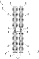
- a further agricultural machine 100c or a pickup device 200c and a pickup roller 1c may include a square tube 17a, which is twisted.
- a twist angle VW of approximately 90 degrees is achieved by an upper square side 18e side surface and a lateral square side 18f bottom.
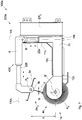
- the Fig. 6 shows a further agricultural machine 100d or pickup device 200d, which substantially the embodiment variant of the Fig. 3 corresponds and thus the already known there components are displayed only with continued indices.
- a 200d integrated hydraulic system 300 in the pickup apparatus for this purpose is a hydraulic oil reservoir HR provided within a housing 32 of a three-point trestle DP. 2
- an oil filter 21 and three hydraulic pumps HP 1 -HP 3 are integrated into the housing 32, preferably in each case a hydraulic pump for controlling a pickup roller 1d, a conveying aid FH 2 and a cross conveyor belt 10b.
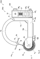
- Fig. 7 1 shows an embodiment variant of an agricultural machine 100e according to the invention or a pickup device 200e according to the invention with an adjustment mechanism 400.
- a support frame 2c and a support arm 7f are each configured as hydraulic pistons 22a and 22b.
- a conveying aid FH 3 is height-adjustable relative to a pickup roller 1e along a vertical axis VA and adjustable along a direction of travel axis FRA such that the conveying aid FH 3 optionally in the direction of travel before, at the same level or behind the pickup roller 1e is arranged.
- the pickup apparatus 200e in a known manner a rotary bearing 3f, in which the pickup roll 1e in a rotation R 5 rotates.
- a sheet profile 9c rotates in opposite directions in a counter-rotation R. 6
- the Fig. 8 shows an agricultural machine 100f and pickup device 200f, which is characterized in that both a pickup roller 1f, as well as a similarly designed conveying aid FH 4 are divided into sub-rollers 23a-23d.
- the sub-rollers 23a and 23b of the conveying aid FH 4 and the sub-rollers 23c and 23c of the pickup roller 1f are respectively connected by a universal joint 24a and 24b.
- a respectively arranged on the sub-rollers 23b and 23d drive 25a and 25b thus also drives the sub-rollers 23a and 23c.
- the universal joints 24a and 24b ensure upward and downward movements depending on the shape of the ground.
- the two universal joints 24a and 24b are mounted telescopically displaceable at least on one side. Furthermore, in order to maintain a height clearance A 1 between the feed roll part rolls 23a-23d, the shafts of the universal joints 24a and 24b are connected to each other with rolling bearing bearings 26a and 26b.
- the pickup roller 1f may be a single, fixed roller, but the conveying aid has a hinge. This joint also allows up and down movements, for example, for receiving particularly thick feeder balls, but is limited by a limitation to a horizontal axis HA 1 .
- an agricultural machine with a pickup device can have individually controlled partial rollers, it would be possible to control the outer sub-roller at a higher rotational speed when describing curves, and thereby in turn the feed or stalk intake could be optimized in the curves ,
- an exemplary conveyor element or profile 4d is shown. It can therefore be a single element, but also a profile that extends over the entire width of the pickup device. It may also be provided for both the pickup, as well as for the conveyor rollers. This applies to all conveyor element or profile design variants 4d-4g shown below.
- the conveyor element or profile 4d forms four individual conveyor tines 5j-5m around an axis center 28a, which in turn each form an extension 27a-27d at their distal ends. These extensions 27a-27d are arranged counter to a rotation R 7 of the conveying element or profile 4d and are intended to prevent the feed or stalk material from getting caught at the ends.
- Fig. 9b shows a further embodiment variant of a conveying element or profile 4e, in which conveyor tines 5n-5q are each offset by an offset V 1 from a center axis 28b.
- Fig. 9c is a star-shaped conveying element or profile 4f shown schematically, in which a rotation Rg can take place either counterclockwise or clockwise.
- the Fig. 9d shows a windmill-like conveying element or profile 4g with against a rotational direction R 10 bent conveyor tines 5v-5y.
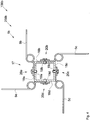
- FIG. 3 is a schematic plan view of how a working insert of an agricultural machine 100g may be configured with a tractor 29a.
- a front-mounted pickup device 200g may be pushed and two pickup devices 200h and 200i staggered with a double drawbar 30a may be pulled.
- a working width AB 1 is composed of an agricultural surface F1, which clears the pickup device 200g, advantageously, without the tractor 29a drüberement over feed or stalk material FG 1 and places it in a swath 31a, for example, in the direction FR 1 right from.
- An agricultural area F 2 with fodder FG 2 including the swath 31a, is picked up by the pickup device 200h recorded and stored in a swath 31b.
- the pickup device 200i which, without another swath, only needs to pick up feed or stalk material FG 3 from an agricultural surface F 3 and deposit it in a swath 31 c. This, in turn, would change as the pickup device 200g changes from right to left deposit by switching the rotation of its cross conveyor.
- the Fig. 10b shows an optional configuration of an agricultural 100h machine in which on a tractor 29b in a direction of travel FR 2 forward in front mounting a pickup device 200j and back again added disposed at a double pole 30b, two pickup devices are mounted 200k and 2001 respectively. In this configuration, the two rear pickup devices 200k and 2001 cooperate with each other and deposit a large swath 31e in the center.
Landscapes
- Life Sciences & Earth Sciences (AREA)
- Environmental Sciences (AREA)
- Soil Working Implements (AREA)
Claims (14)
- Machine agricole (100, 100a-100h) avec une direction de déplacement (FR1, FR2) et un axe de direction de déplacement (FRA) et avec au moins un dispositif de ramassage (200, 200a-2001), où le dispositif de ramassage (200, 200a-2001) comprend au moins un rouleau de ramassage (1, 1a-1f) rotatif dans une rotation (R1, R3, R5) et au moyen d'au moins un entraînement de rotation (RA1), avec des éléments de transport (4, 4a-4g) et des dents de transport (5, 5a-5y) pour la prise du fourrage ou des tiges du fourrage (FG1-FG6) d'une surface agricole (F1-F6) aussi bien qu'au moins un auxiliaire de transport (FH, FH1-FH4) rotatif dans une contre-rotation (R2, R4, R6), l'auxiliaire de transport (FH, FH1-FH4) étant entraîné par au moins un entraînement de rotation (RA2), caractérisée en ce qu'un mécanisme de réglage (400) est prévu pour l'auxiliaire de transport (FH3) et un écartement vertical en hauteur (A) ainsi qu'un décalage horizontal (V) de l'axe de rotation de l'auxiliaire de transport (FH3) le long de l'axe de déplacement (FRA) sont réglables au choix devant, à distance égale ou derrière l'axe de rotation du rouleau de ramassage (le).
- Machine agricole (100, 100a-100h) avec au moins un auxiliaire de ramassage (200, 200a-2001), selon la revendication 1, caractérisée en ce que les dents de transport (5a, 5h, 5i) du rouleau de ramassage (1, 1a-1f) et/ou l'auxiliaire de transport (FH, FH1-FH4) sont disposées en au moins une rangée hélicoïdale de dents (ZR4-ZR7).
- Machine agricole (100, 100a-100h) avec au moins un auxiliaire de ramassage (200, 200a-2001), selon l'une des revendications précédentes, caractérisée en ce que l'auxiliaire de ramassage (200, 200a-2001) comprend une bande transporteuse transversale (10, 10a-10c) qui, au moyen d'un entraînement rotatif (RA3), est rotative dans ou contre le sens horaire.
- Machine agricole (100, 100a-100h) avec au moins un dispositif de ramassage (200, 200a-2001), selon l'une des revendications précédentes, caractérisée en ce que le dispositif de ramassage (200, 200a-2001) comprend un attelage trois points (DP, DP1-DP3) qui est fixé au dispositif de ramassage (200, 200a-2001) ou à un cadre de support (2, 2a-2c) du dispositif de ramassage (200, 200a-2001) dans une suspension à tube pendulaire (16, 16a, 16b) et est pivotant dans un mouvement pendulaire (PB) autour d'un axe pendulaire (PA).
- Machine agricole (100, 100a-100h) avec au moins un dispositif de ramassage (200, 200a-2001), selon la revendication précédente 4, caractérisée en ce que la suspension à tube pendulaire (16, 16a, 16b) est à ressort.
- Machine agricole (100, 100a-100h) avec au moins un dispositif de ramassage (200, 200a-2001) selon l'une des revendications précédentes, caractérisée en ce que l'entraînement rotatif (RA1) du rouleau de ramassage (1, 1a-1f) est couplé à l'entraînement rotatif (RA2) de l'auxiliaire de transport (FH, FH1-FH4).
- Machine agricole (100, 100a-100h) avec au moins un dispositif de ramassage (200, 200a-2001), selon l'une des revendications précédentes 1-5, caractérisée en ce que l'entraînement rotatif (RA1) du rouleau de ramassage (1, 1a-1f), l'entraînement rotatif (RA2) de l'auxiliaire de transport (FH, FH1-FH4) et l'entraînement rotatif (RA3) de la bande transporteuse transversale (10, 10a-10c) sont manoeuvrable séparément et individuellement.
- Machine agricole (100, 100a-100h) avec au moins un dispositif de ramassage (200, 200a-2001), selon l'une des revendications précédentes 6 ou 7, caractérisée en ce que les entraînements rotatifs (RA1-RA3) sont commandables à distance.
- Machine agricole (100, 100a-100h) avec au moins un dispositif de ramassage (200, 200a-2001), selon l'une des revendications précédentes, caractérisée en ce que le rouleau de ramassage (1, 1a-1f) comprend au moins deux rouleaux partiels (23c, 23d).
- Machine agricole (100f) avec au moins un dispositif de ramassage (200f), selon la revendication précédente 9, caractérisée en ce que l'auxiliaire de transport (FH4) comprend également au moins deux rouleaux partiels (23a, 23b) et les rouleaux partiels (23a-23d) sont reliés entre eux par des joints de cardan (24a, 24b).
- Machine agricole (100, 100a-100h) avec au moins un dispositif de ramassage (200, 200a-2001), selon l'une des revendications précédentes, caractérisée en ce que l'auxiliaire de transport (FH, FH1-FH4) comprend au moins un rouleau de transport avec des éléments de transport individuels (4, 4a-4g).
- Machine agricole (100, 100a-100h) avec au moins un dispositif de ramassage (200, 200a-2001), selon l'une des revendications précédentes 1-10, caractérisée en ce que l'auxiliaire de transport (FH, FH1-FH4) comprend un profil de transport (4, 4a-4g, 9, 9a-9c).
- Machine agricole (100, 100a-100h) avec au moins un dispositif de ramassage (200, 200a-2001), selon l'une des revendications précédentes, caractérisée en ce que le rouleau de ramassage (1, 1a-1f) et/ou le rouleau de transport comprend un tuyau carré (17, 17a) avec des côtés carrés (18a-18f) sur lesquels sont disposées les dents de transport (5, 5a-5y).
- Procédé pour formage et dépôt des andains (31a-31e) de fourrage ou de tiges du fourrage (FG1-FG6) avec une machine agricole (100e) avec une direction de déplacement (FR1, FR2) et un axe de direction de déplacement (FRA) et avec au moins un dispositif de ramassage (200e) selon l'une des revendications précédentes 3-13, caractérisé en ce que les étapes suivantes sont exécutées:a)- actionnement du premier entraînement rotatif (RA5) du rouleau de ramassage (1e);b)- actionnement du deuxième, tournant en sens inverse, entraînement rotatif (RA6) de l'auxiliaire de transport (FH3);c)- actionnement du troisième entraînement rotatif (RA3) de la bande transporteuse transversale (10c);d)- réglage et adaptation des vitesses de rotation des trois entraînements rotatifs (RA5, RA6, RA3) les uns aux autres;e)- réglage d'un écartement vertical en hauteur (A) et d'un décalage horizontal (V) de l'axe de rotation de l'auxiliaire de transport (FH3) le long de l'axe de déplacement (FRA) devant, à distance égale ou derrière l'axe de rotation du rouleau de ramassage (1e);f)- mise en mouvement de la machine agricole (100e) sur une surface agricole (F1-F6) avec du fourrage ou des tiges du fourrage (FG1-FG6) ;g)- réglage et adaptation des vitesses de rotation des trois entraînements rotatifs (RA5, RA6, RA3) pendant le déplacement ;h)- réglage et adaptation de l'écartement vertical en hauteur (A) et du décalage horizontal (V) de l'axe de rotation de l'auxiliaire de transport (FH3) le long de l'axe de déplacement (FRA) devant, à distance égale ou derrière l'axe de rotation du rouleau de ramassage (1e).
Priority Applications (1)
| Application Number | Priority Date | Filing Date | Title |
|---|---|---|---|
| EP15002536.9A EP3135099B1 (fr) | 2015-08-27 | 2015-08-27 | Machine agricole comprenant un dispositif de ramassage |
Applications Claiming Priority (1)
| Application Number | Priority Date | Filing Date | Title |
|---|---|---|---|
| EP15002536.9A EP3135099B1 (fr) | 2015-08-27 | 2015-08-27 | Machine agricole comprenant un dispositif de ramassage |
Publications (2)
| Publication Number | Publication Date |
|---|---|
| EP3135099A1 EP3135099A1 (fr) | 2017-03-01 |
| EP3135099B1 true EP3135099B1 (fr) | 2019-10-09 |
Family
ID=54011943
Family Applications (1)
| Application Number | Title | Priority Date | Filing Date |
|---|---|---|---|
| EP15002536.9A Active EP3135099B1 (fr) | 2015-08-27 | 2015-08-27 | Machine agricole comprenant un dispositif de ramassage |
Country Status (1)
| Country | Link |
|---|---|
| EP (1) | EP3135099B1 (fr) |
Families Citing this family (10)
| Publication number | Priority date | Publication date | Assignee | Title |
|---|---|---|---|---|
| AT15441U1 (de) * | 2016-11-24 | 2017-09-15 | Knüsel Josef | Landwirtschaftliche Maschine mit einer Pickup-Vorrichtung |
| EP3437456A1 (fr) * | 2017-08-03 | 2019-02-06 | I.G. S.R.L. | Unité de râtelage |
| CN107471714B (zh) * | 2017-09-04 | 2023-02-24 | 安阳工学院 | 田间移动式秸秆致密成型设备 |
| CN107873253A (zh) * | 2017-11-12 | 2018-04-06 | 南通飞奔机械有限公司 | 用于秸秆收集机的铲拾夹送联合机构 |
| CN108738719B (zh) * | 2018-07-25 | 2024-03-26 | 中国农业机械化科学研究院呼和浩特分院有限公司 | 牧草捡拾集条机 |
| CN108848945A (zh) * | 2018-08-24 | 2018-11-23 | 杨晓昀 | 一种用于秸秆和牧草的捡拾装置 |
| DE202018107018U1 (de) | 2018-12-10 | 2019-01-16 | Pöttinger Landtechnik Gmbh | Landwirtschaftliche Erntemaschine |
| DE202018107313U1 (de) | 2018-12-20 | 2020-03-23 | Pöttinger Landtechnik Gmbh | Landwirtschaftliche Erntemaschine |
| CH717350A1 (de) * | 2020-04-28 | 2021-10-29 | Meier Philipp | Rundballenpresse mit Feldhäcksler. |
| DE202022105171U1 (de) | 2022-09-14 | 2023-12-19 | Pöttinger Landtechnik Gmbh | Landwirtschaftliche Erntemaschine |
Family Cites Families (5)
| Publication number | Priority date | Publication date | Assignee | Title |
|---|---|---|---|---|
| NL1004768C2 (nl) * | 1996-12-13 | 1998-07-02 | Abraham Lorier | Werkwijze en inrichting voor het bewerken van maaigoed. |
| DE10320042A1 (de) * | 2002-11-20 | 2004-06-17 | Götz, Walter | Landwirtschaftsmaschine zum Kreiseln und Schwadern von gemähtem Bodenwuchs |
| DE102010006026A1 (de) * | 2010-01-27 | 2011-07-28 | Maschinenfabrik Stolpen GmbH, 01833 | Lastspitzenfreie Aufnahmeeinrichtung für am Boden liegendes Erntegut |
| DE202010010038U1 (de) * | 2010-07-09 | 2011-11-02 | Alois Pöttinger Maschinenfabrik Gmbh | Erntemaschine |
| US20150096628A1 (en) * | 2013-10-04 | 2015-04-09 | Derek W. Kent | Three point attachment with hydraulic quick attach |
-
2015
- 2015-08-27 EP EP15002536.9A patent/EP3135099B1/fr active Active
Non-Patent Citations (1)
| Title |
|---|
| None * |
Also Published As
| Publication number | Publication date |
|---|---|
| EP3135099A1 (fr) | 2017-03-01 |
Similar Documents
| Publication | Publication Date | Title |
|---|---|---|
| EP3135099B1 (fr) | Machine agricole comprenant un dispositif de ramassage | |
| EP1048199B1 (fr) | Rabatteur pour machine de récolte | |
| DE10302692B4 (de) | Antriebssystem für einen Erntevorsatz einer Erntemaschine | |
| DE102005016350A1 (de) | Erntevorsatz für landwirtschaftliche Erntemaschinen | |
| DE2843775A1 (de) | Gabellose heuerntemaschine | |
| EP2901842B1 (fr) | Dispositif de transport pouvant être raccordé par entraînement à une machine de travail guidée manuellement et présentant un axe mobile entraîné | |
| EP3326448A1 (fr) | Machine agricole comprenant un dispositif de ramassage | |
| EP1093707B1 (fr) | Véhicule automobile agricole | |
| EP1068791A1 (fr) | Faucheuse automotrice munie de convoyeurs | |
| DE19952555A1 (de) | Heuwerbungsmaschine | |
| DE102008042392B4 (de) | Erntevorsatz für landwirtschaftliche Erntemaschinen | |
| DE102011053352A1 (de) | Fahrgassenräumer | |
| CH711210B1 (de) | Landwirtschaftliche Maschine mit einer Pickup-Vorrichtung. | |
| DE2922887C2 (de) | Heuwerbungsmaschine | |
| DE102011113121A1 (de) | Kombinierbarer Sternradschwader | |
| EP1932415B1 (fr) | Dispositif muni d'une première et d'une seconde unité de travail | |
| DE2001374A1 (de) | Maehwerk | |
| EP3058804B1 (fr) | Faneuse | |
| WO2013034480A1 (fr) | Andaineur à tapis | |
| EP2510767B1 (fr) | Véhicule à un seul essieu | |
| EP1929854B1 (fr) | Dispositif de réception destiné à la réception de récoltes au sol | |
| DE2249318C3 (de) | Heuwerbungsmaschine | |
| EP2946653B1 (fr) | Andaineur, notamment râteau-soleil | |
| DE102007060962A1 (de) | Erntevorsatzvorrichtung zum Aufnehmen von am Boden liegendem Erntegut | |
| DE202006018588U1 (de) | Aufnahmevorrichtung zum Aufnehmen von am Boden liegenden Erntegut |
Legal Events
| Date | Code | Title | Description |
|---|---|---|---|
| PUAI | Public reference made under article 153(3) epc to a published international application that has entered the european phase |
Free format text: ORIGINAL CODE: 0009012 |
|
| STAA | Information on the status of an ep patent application or granted ep patent |
Free format text: STATUS: THE APPLICATION HAS BEEN PUBLISHED |
|
| AK | Designated contracting states |
Kind code of ref document: A1 Designated state(s): AL AT BE BG CH CY CZ DE DK EE ES FI FR GB GR HR HU IE IS IT LI LT LU LV MC MK MT NL NO PL PT RO RS SE SI SK SM TR |
|
| AX | Request for extension of the european patent |
Extension state: BA ME |
|
| STAA | Information on the status of an ep patent application or granted ep patent |
Free format text: STATUS: REQUEST FOR EXAMINATION WAS MADE |
|
| 17P | Request for examination filed |
Effective date: 20171227 |
|
| RBV | Designated contracting states (corrected) |
Designated state(s): AL AT BE BG CH CY CZ DE DK EE ES FI FR GB GR HR HU IE IS IT LI LT LU LV MC MK MT NL NO PL PT RO RS SE SI SK SM TR |
|
| STAA | Information on the status of an ep patent application or granted ep patent |
Free format text: STATUS: EXAMINATION IS IN PROGRESS |
|
| 17Q | First examination report despatched |
Effective date: 20180628 |
|
| GRAP | Despatch of communication of intention to grant a patent |
Free format text: ORIGINAL CODE: EPIDOSNIGR1 |
|
| STAA | Information on the status of an ep patent application or granted ep patent |
Free format text: STATUS: GRANT OF PATENT IS INTENDED |
|
| INTG | Intention to grant announced |
Effective date: 20190408 |
|
| GRAS | Grant fee paid |
Free format text: ORIGINAL CODE: EPIDOSNIGR3 |
|
| GRAA | (expected) grant |
Free format text: ORIGINAL CODE: 0009210 |
|
| STAA | Information on the status of an ep patent application or granted ep patent |
Free format text: STATUS: THE PATENT HAS BEEN GRANTED |
|
| AK | Designated contracting states |
Kind code of ref document: B1 Designated state(s): AL AT BE BG CH CY CZ DE DK EE ES FI FR GB GR HR HU IE IS IT LI LT LU LV MC MK MT NL NO PL PT RO RS SE SI SK SM TR |
|
| REG | Reference to a national code |
Ref country code: GB Ref legal event code: FG4D Free format text: NOT ENGLISH |
|
| REG | Reference to a national code |
Ref country code: CH Ref legal event code: EP |
|
| REG | Reference to a national code |
Ref country code: DE Ref legal event code: R096 Ref document number: 502015010558 Country of ref document: DE |
|
| REG | Reference to a national code |
Ref country code: IE Ref legal event code: FG4D Free format text: LANGUAGE OF EP DOCUMENT: GERMAN |
|
| REG | Reference to a national code |
Ref country code: AT Ref legal event code: REF Ref document number: 1187701 Country of ref document: AT Kind code of ref document: T Effective date: 20191115 |
|
| REG | Reference to a national code |
Ref country code: CH Ref legal event code: NV Representative=s name: PATENT- AND MARKENBUERO REB GMBH, CH |
|
| REG | Reference to a national code |
Ref country code: NL Ref legal event code: MP Effective date: 20191009 |
|
| REG | Reference to a national code |
Ref country code: LT Ref legal event code: MG4D |
|
| PG25 | Lapsed in a contracting state [announced via postgrant information from national office to epo] |
Ref country code: ES Free format text: LAPSE BECAUSE OF FAILURE TO SUBMIT A TRANSLATION OF THE DESCRIPTION OR TO PAY THE FEE WITHIN THE PRESCRIBED TIME-LIMIT Effective date: 20191009 Ref country code: LV Free format text: LAPSE BECAUSE OF FAILURE TO SUBMIT A TRANSLATION OF THE DESCRIPTION OR TO PAY THE FEE WITHIN THE PRESCRIBED TIME-LIMIT Effective date: 20191009 Ref country code: GR Free format text: LAPSE BECAUSE OF FAILURE TO SUBMIT A TRANSLATION OF THE DESCRIPTION OR TO PAY THE FEE WITHIN THE PRESCRIBED TIME-LIMIT Effective date: 20200110 Ref country code: SE Free format text: LAPSE BECAUSE OF FAILURE TO SUBMIT A TRANSLATION OF THE DESCRIPTION OR TO PAY THE FEE WITHIN THE PRESCRIBED TIME-LIMIT Effective date: 20191009 Ref country code: BG Free format text: LAPSE BECAUSE OF FAILURE TO SUBMIT A TRANSLATION OF THE DESCRIPTION OR TO PAY THE FEE WITHIN THE PRESCRIBED TIME-LIMIT Effective date: 20200109 Ref country code: FI Free format text: LAPSE BECAUSE OF FAILURE TO SUBMIT A TRANSLATION OF THE DESCRIPTION OR TO PAY THE FEE WITHIN THE PRESCRIBED TIME-LIMIT Effective date: 20191009 Ref country code: NO Free format text: LAPSE BECAUSE OF FAILURE TO SUBMIT A TRANSLATION OF THE DESCRIPTION OR TO PAY THE FEE WITHIN THE PRESCRIBED TIME-LIMIT Effective date: 20200109 Ref country code: PL Free format text: LAPSE BECAUSE OF FAILURE TO SUBMIT A TRANSLATION OF THE DESCRIPTION OR TO PAY THE FEE WITHIN THE PRESCRIBED TIME-LIMIT Effective date: 20191009 Ref country code: LT Free format text: LAPSE BECAUSE OF FAILURE TO SUBMIT A TRANSLATION OF THE DESCRIPTION OR TO PAY THE FEE WITHIN THE PRESCRIBED TIME-LIMIT Effective date: 20191009 Ref country code: PT Free format text: LAPSE BECAUSE OF FAILURE TO SUBMIT A TRANSLATION OF THE DESCRIPTION OR TO PAY THE FEE WITHIN THE PRESCRIBED TIME-LIMIT Effective date: 20200210 Ref country code: NL Free format text: LAPSE BECAUSE OF FAILURE TO SUBMIT A TRANSLATION OF THE DESCRIPTION OR TO PAY THE FEE WITHIN THE PRESCRIBED TIME-LIMIT Effective date: 20191009 |
|
| PG25 | Lapsed in a contracting state [announced via postgrant information from national office to epo] |
Ref country code: HR Free format text: LAPSE BECAUSE OF FAILURE TO SUBMIT A TRANSLATION OF THE DESCRIPTION OR TO PAY THE FEE WITHIN THE PRESCRIBED TIME-LIMIT Effective date: 20191009 Ref country code: IS Free format text: LAPSE BECAUSE OF FAILURE TO SUBMIT A TRANSLATION OF THE DESCRIPTION OR TO PAY THE FEE WITHIN THE PRESCRIBED TIME-LIMIT Effective date: 20200224 Ref country code: RS Free format text: LAPSE BECAUSE OF FAILURE TO SUBMIT A TRANSLATION OF THE DESCRIPTION OR TO PAY THE FEE WITHIN THE PRESCRIBED TIME-LIMIT Effective date: 20191009 |
|
| PG25 | Lapsed in a contracting state [announced via postgrant information from national office to epo] |
Ref country code: AL Free format text: LAPSE BECAUSE OF FAILURE TO SUBMIT A TRANSLATION OF THE DESCRIPTION OR TO PAY THE FEE WITHIN THE PRESCRIBED TIME-LIMIT Effective date: 20191009 |
|
| REG | Reference to a national code |
Ref country code: DE Ref legal event code: R097 Ref document number: 502015010558 Country of ref document: DE |
|
| PG2D | Information on lapse in contracting state deleted |
Ref country code: IS |
|
| PG25 | Lapsed in a contracting state [announced via postgrant information from national office to epo] |
Ref country code: RO Free format text: LAPSE BECAUSE OF FAILURE TO SUBMIT A TRANSLATION OF THE DESCRIPTION OR TO PAY THE FEE WITHIN THE PRESCRIBED TIME-LIMIT Effective date: 20191009 Ref country code: CZ Free format text: LAPSE BECAUSE OF FAILURE TO SUBMIT A TRANSLATION OF THE DESCRIPTION OR TO PAY THE FEE WITHIN THE PRESCRIBED TIME-LIMIT Effective date: 20191009 Ref country code: EE Free format text: LAPSE BECAUSE OF FAILURE TO SUBMIT A TRANSLATION OF THE DESCRIPTION OR TO PAY THE FEE WITHIN THE PRESCRIBED TIME-LIMIT Effective date: 20191009 Ref country code: DK Free format text: LAPSE BECAUSE OF FAILURE TO SUBMIT A TRANSLATION OF THE DESCRIPTION OR TO PAY THE FEE WITHIN THE PRESCRIBED TIME-LIMIT Effective date: 20191009 Ref country code: IS Free format text: LAPSE BECAUSE OF FAILURE TO SUBMIT A TRANSLATION OF THE DESCRIPTION OR TO PAY THE FEE WITHIN THE PRESCRIBED TIME-LIMIT Effective date: 20200209 |
|
| PLBE | No opposition filed within time limit |
Free format text: ORIGINAL CODE: 0009261 |
|
| STAA | Information on the status of an ep patent application or granted ep patent |
Free format text: STATUS: NO OPPOSITION FILED WITHIN TIME LIMIT |
|
| PG25 | Lapsed in a contracting state [announced via postgrant information from national office to epo] |
Ref country code: SM Free format text: LAPSE BECAUSE OF FAILURE TO SUBMIT A TRANSLATION OF THE DESCRIPTION OR TO PAY THE FEE WITHIN THE PRESCRIBED TIME-LIMIT Effective date: 20191009 Ref country code: IT Free format text: LAPSE BECAUSE OF FAILURE TO SUBMIT A TRANSLATION OF THE DESCRIPTION OR TO PAY THE FEE WITHIN THE PRESCRIBED TIME-LIMIT Effective date: 20191009 Ref country code: SK Free format text: LAPSE BECAUSE OF FAILURE TO SUBMIT A TRANSLATION OF THE DESCRIPTION OR TO PAY THE FEE WITHIN THE PRESCRIBED TIME-LIMIT Effective date: 20191009 |
|
| 26N | No opposition filed |
Effective date: 20200710 |
|
| PG25 | Lapsed in a contracting state [announced via postgrant information from national office to epo] |
Ref country code: SI Free format text: LAPSE BECAUSE OF FAILURE TO SUBMIT A TRANSLATION OF THE DESCRIPTION OR TO PAY THE FEE WITHIN THE PRESCRIBED TIME-LIMIT Effective date: 20191009 |
|
| PG25 | Lapsed in a contracting state [announced via postgrant information from national office to epo] |
Ref country code: MC Free format text: LAPSE BECAUSE OF FAILURE TO SUBMIT A TRANSLATION OF THE DESCRIPTION OR TO PAY THE FEE WITHIN THE PRESCRIBED TIME-LIMIT Effective date: 20191009 |
|
| GBPC | Gb: european patent ceased through non-payment of renewal fee |
Effective date: 20200827 |
|
| PG25 | Lapsed in a contracting state [announced via postgrant information from national office to epo] |
Ref country code: LU Free format text: LAPSE BECAUSE OF NON-PAYMENT OF DUE FEES Effective date: 20200827 |
|
| REG | Reference to a national code |
Ref country code: BE Ref legal event code: MM Effective date: 20200831 |
|
| PG25 | Lapsed in a contracting state [announced via postgrant information from national office to epo] |
Ref country code: FR Free format text: LAPSE BECAUSE OF NON-PAYMENT OF DUE FEES Effective date: 20200831 |
|
| PG25 | Lapsed in a contracting state [announced via postgrant information from national office to epo] |
Ref country code: BE Free format text: LAPSE BECAUSE OF NON-PAYMENT OF DUE FEES Effective date: 20200831 Ref country code: GB Free format text: LAPSE BECAUSE OF NON-PAYMENT OF DUE FEES Effective date: 20200827 Ref country code: IE Free format text: LAPSE BECAUSE OF NON-PAYMENT OF DUE FEES Effective date: 20200827 |
|
| PG25 | Lapsed in a contracting state [announced via postgrant information from national office to epo] |
Ref country code: TR Free format text: LAPSE BECAUSE OF FAILURE TO SUBMIT A TRANSLATION OF THE DESCRIPTION OR TO PAY THE FEE WITHIN THE PRESCRIBED TIME-LIMIT Effective date: 20191009 Ref country code: MT Free format text: LAPSE BECAUSE OF FAILURE TO SUBMIT A TRANSLATION OF THE DESCRIPTION OR TO PAY THE FEE WITHIN THE PRESCRIBED TIME-LIMIT Effective date: 20191009 Ref country code: CY Free format text: LAPSE BECAUSE OF FAILURE TO SUBMIT A TRANSLATION OF THE DESCRIPTION OR TO PAY THE FEE WITHIN THE PRESCRIBED TIME-LIMIT Effective date: 20191009 |
|
| PG25 | Lapsed in a contracting state [announced via postgrant information from national office to epo] |
Ref country code: MK Free format text: LAPSE BECAUSE OF FAILURE TO SUBMIT A TRANSLATION OF THE DESCRIPTION OR TO PAY THE FEE WITHIN THE PRESCRIBED TIME-LIMIT Effective date: 20191009 |
|
| PGFP | Annual fee paid to national office [announced via postgrant information from national office to epo] |
Ref country code: AT Payment date: 20230901 Year of fee payment: 9 |
|
| PGFP | Annual fee paid to national office [announced via postgrant information from national office to epo] |
Ref country code: DE Payment date: 20240227 Year of fee payment: 9 Ref country code: CH Payment date: 20240227 Year of fee payment: 9 |