EP3133005B1 - Structure for front part of saddled vehicle - Google Patents
Structure for front part of saddled vehicle Download PDFInfo
- Publication number
- EP3133005B1 EP3133005B1 EP15780262.0A EP15780262A EP3133005B1 EP 3133005 B1 EP3133005 B1 EP 3133005B1 EP 15780262 A EP15780262 A EP 15780262A EP 3133005 B1 EP3133005 B1 EP 3133005B1
- Authority
- EP
- European Patent Office
- Prior art keywords
- windshield
- covering
- meter
- front wall
- forwardly
- Prior art date
- Legal status (The legal status is an assumption and is not a legal conclusion. Google has not performed a legal analysis and makes no representation as to the accuracy of the status listed.)
- Active
Links
Images


Classifications
-
- B—PERFORMING OPERATIONS; TRANSPORTING
- B62—LAND VEHICLES FOR TRAVELLING OTHERWISE THAN ON RAILS
- B62J—CYCLE SADDLES OR SEATS; AUXILIARY DEVICES OR ACCESSORIES SPECIALLY ADAPTED TO CYCLES AND NOT OTHERWISE PROVIDED FOR, e.g. ARTICLE CARRIERS OR CYCLE PROTECTORS
- B62J6/00—Arrangement of optical signalling or lighting devices on cycles; Mounting or supporting thereof; Circuits therefor
- B62J6/02—Headlights
- B62J6/022—Headlights specially adapted for motorcycles or the like
- B62J6/027—Supporting means therefor, e.g. mounting brackets
-
- B—PERFORMING OPERATIONS; TRANSPORTING
- B62—LAND VEHICLES FOR TRAVELLING OTHERWISE THAN ON RAILS
- B62J—CYCLE SADDLES OR SEATS; AUXILIARY DEVICES OR ACCESSORIES SPECIALLY ADAPTED TO CYCLES AND NOT OTHERWISE PROVIDED FOR, e.g. ARTICLE CARRIERS OR CYCLE PROTECTORS
- B62J17/00—Weather guards for riders; Fairings or stream-lining parts not otherwise provided for
- B62J17/02—Weather guards for riders; Fairings or stream-lining parts not otherwise provided for shielding only the rider's front
- B62J17/04—Windscreens
-
- B—PERFORMING OPERATIONS; TRANSPORTING
- B62—LAND VEHICLES FOR TRAVELLING OTHERWISE THAN ON RAILS
- B62J—CYCLE SADDLES OR SEATS; AUXILIARY DEVICES OR ACCESSORIES SPECIALLY ADAPTED TO CYCLES AND NOT OTHERWISE PROVIDED FOR, e.g. ARTICLE CARRIERS OR CYCLE PROTECTORS
- B62J23/00—Other protectors specially adapted for cycles
-
- B—PERFORMING OPERATIONS; TRANSPORTING
- B62—LAND VEHICLES FOR TRAVELLING OTHERWISE THAN ON RAILS
- B62J—CYCLE SADDLES OR SEATS; AUXILIARY DEVICES OR ACCESSORIES SPECIALLY ADAPTED TO CYCLES AND NOT OTHERWISE PROVIDED FOR, e.g. ARTICLE CARRIERS OR CYCLE PROTECTORS
- B62J50/00—Arrangements specially adapted for use on cycles not provided for in main groups B62J1/00 - B62J45/00
- B62J50/20—Information-providing devices
- B62J50/21—Information-providing devices intended to provide information to rider or passenger
- B62J50/225—Mounting arrangements therefor
-
- B—PERFORMING OPERATIONS; TRANSPORTING
- B62—LAND VEHICLES FOR TRAVELLING OTHERWISE THAN ON RAILS
- B62J—CYCLE SADDLES OR SEATS; AUXILIARY DEVICES OR ACCESSORIES SPECIALLY ADAPTED TO CYCLES AND NOT OTHERWISE PROVIDED FOR, e.g. ARTICLE CARRIERS OR CYCLE PROTECTORS
- B62J6/00—Arrangement of optical signalling or lighting devices on cycles; Mounting or supporting thereof; Circuits therefor
- B62J6/02—Headlights
- B62J6/022—Headlights specially adapted for motorcycles or the like
- B62J6/026—Headlights specially adapted for motorcycles or the like characterised by the structure, e.g. casings
-
- B—PERFORMING OPERATIONS; TRANSPORTING
- B62—LAND VEHICLES FOR TRAVELLING OTHERWISE THAN ON RAILS
- B62J—CYCLE SADDLES OR SEATS; AUXILIARY DEVICES OR ACCESSORIES SPECIALLY ADAPTED TO CYCLES AND NOT OTHERWISE PROVIDED FOR, e.g. ARTICLE CARRIERS OR CYCLE PROTECTORS
- B62J50/00—Arrangements specially adapted for use on cycles not provided for in main groups B62J1/00 - B62J45/00
- B62J50/20—Information-providing devices
- B62J50/21—Information-providing devices intended to provide information to rider or passenger
Definitions
- the present invention relates to a saddled vehicle or saddle riding vehicle comprising a front structure which is equipped with a meter unit, a meter covering for covering an area forwardly of the meter unit and a windshield disposed forwardly of the meter covering.
- a windshield mounted on an upper portion of a vehicle body front portion.
- the windshield referred to above functions as a wind blocking function to prevent the wind from impinging upon a rider.
- a meter unit for displaying, for example, the speed and the rotational number and a meter covering for covering the meter unit are disposed rearwardly of the windshield.
- Patent Document 1 JP Laid-open Patent Publication No. 2013-091387
- the windshield referred to above is so designed and so configured in order to reduce the air resistance as to represent a curved shape having been upwardly rearwardly inclined, when viewed from lateral side, and also having been bulged forwardly from opposite side portions thereof towards an intermediate portion thereof to represent a curved shape when viewed from front. For this reason, particularly during the parking, sunlight from rear reflects upon a rear surface of the windshield and is subsequently focused upon the meter covering, thus bringing about adverse effects on the meter covering.
- EP 2 703 269 A1 and JP 2009 214723 A disclose other saddle-riding vehicles having some of the features of this invention
- EP 1 291 274 A2 discloses the features of the preamble of claim 1.
- a saddle-riding vehicle comprising a front structure which is capable of suppressing the influence of the adverse effects which is brought about by the sunlight upon the meter covering.
- the saddle-riding vehicle herein provided in accordance with the present invention comprises a front structure according to the features of appended claim 1.
- the front wall of the meter covering is so designed and shaped as to depart from the focal point of light coming from rear and reflected upon the windshield and, therefore, the reflected light is never focused on the meter covering. Accordingly, it is possible to suppress the adverse effect which the reflected light from the windshield brings about on the meter covering.
- the meter covering referred to above may have an extension which extends from an upper end portion of the front wall in a direction rearwardly to thereby cover an area above the meter unit, and the extension referred to above, when viewed from lateral side, preferably has a rear end that is positioned rearwardly of a rear end of the windshield. According to this construction, the area above the meter unit is covered by the extension and, therefore, it is possible to avoid a ghost on the windshield which would be brought about when the sunlight reflects upon a meter display surface.
- the windshield referred to above is fitted for sliding movement in a vertical direction.
- the windshield is preferably positioned upwardly of a front fairing having a headlamp mounted thereon and is supported by a vehicle frame structure through a shield bracket that extends through the meter covering in the vertical direction, and the windshield is slidable substantially parallel to a lower half portion of the front wall along the shield bracket.
- the front wall referred to above preferably has a forwardly protruding shape protruding forwardly from opposite side portions toward an intermediate portion, and the front wall includes a lower half portion from a lower end portion to an intermediate portion in the vertical direction and an upper half portion from the intermediate portion to an upper end portion, in which case the lower half portion preferably extends along the windshield while the upper half portion extends inclined rearwardly so as to allow the front wall to depart from the windshield.
- the upper half portion of the front wall extends having been inclined at the angle of inclination ⁇ that is within the range of 25 to 35° relative to a horizontal surface. According to this construction, the forward sight through the windshield is not disturbed by a rear end portion of the meter covering.
- the meter covering may include an outer covering segment and an inner covering segment, the outer covering segment and the inner covering segment being connected with each other, in which case the meter unit is mounted on the inner covering segment whereas the front wall is formed in the outer covering segment. According to this construction, the meter covering of a large size can be easily formed.
- the front structure for the saddle-riding vehicle may also include a front fairing having the headlamp mounted thereon and a side fairing disposed on each lateral side of the front fairing to cover a region from at least an outer side of a head pipe and an outer side forwardly of an engine, in which case the meter covering is fitted to the front fairing and the side fairing. According to this construction, the meter covering of the large size can be stably supported.
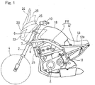
- the motorcycle to which the present invention is applied includes a main frame 1 forming a front half portion of a vehicle frame structure FR, and a front fork 2 is supported by a front end of the main frame 1 with a front wheel 4 supported at a lower end portion of such front fork 2.
- the front fork 2 referred to above is rotatably supported by a head pipe 8 at the front end of the main frame 1 together with an upper bracket 6 and a lower bracket 7 both supporting the front fork 2.
- a handlebar 10 is fitted to the upper bracket 6.
- a swingarm bracket 11 is secured to a rear end lower portion of the main frame 1, and a swingarm (not shown) for supporting a rear wheel 8 is pivotally supported by the swingarm bracket 11.
- a combustion engine E for driving the rear wheel is supported by a lower intermediate portion of the main frame 1.
- a rear frame 12 forming a rear half portion of the vehicle frame structure FR is connected with a rear portion of the main frame 1.
- a rider's seat 13 is supported on a seat rail 112a forming an upper portion of the rear frame 12.
- a fuel tank 18 is positioned on an upper portion of the main frame 1, that is, on a vehicle upper portion between the head pipe 8 and the rider's seat 13.
- a meter unit 26 and a meter covering 28 are disposed rearwardly of the windshield 24.
- the meter covering 28 is made of a resinous material and covers an area forwardly of, opposite lateral sides of and above the meter unit 26.
- the front fairing 20 has a pair of left and right side fairings 25 disposed on opposite sides of the front fairing 20 to thereby cover an area from lateral outer sides of the head pipe 8 to forwardly of the combustion engine E.
- the front fairing 20, the windshield 24 and the side fairings 25, all referred to above, are supported by the main frame 1 through cowl stays 45 (as best shown in Fig. 8 ).
- the windshield 24 is slidably fitted to a vehicle body for adjustment in a vertical direction and is disposed in a fashion inclined upwardly rearwardly when viewed from lateral side.
- a slide structure for the windshield 24 will be described in detail later.
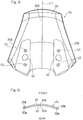
- Fig. 5 is a rear view of the windshield 24.
- the windshield 24 is of a bilaterally symmetrical shape with respect to a center line C1.
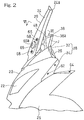
- Fig. 6 illustrates a section taken along the line VI-VI in Fig. 2 , that is a transverse section perpendicular to a lateral or vehicle widthwise direction intermediate portion of a front surface 29 of the windshield 24 shown in Fig. 2 .
- the windshield 24 is of a plate shape while representing a forwardly curved shape with its front and rear surface 29 and 30 protruding forwardly respectively from left and right bilateral end portions 29a and 30a thereof towards an intermediate portion 29b and 30b.
- Bolt insertion holes 40 are formed in left and right bilateral side portions of a lower portion of the windshield 24 as shown in Fig. 5 .
- Two rows of the bolt insertion holes 40 are employed in the instance now under discussion, each row including the two bolt insertion holes 40 juxtaposed in a vertical direction.
- An opening 42 in the form of a throughhole is formed between the bolt insertion holes 40 and 40 of each row in the vertical direction.
- the meter covering 28 includes an outer covering segment 32 and an inner covering segment 34, both of which are joined as at a joint face J (best shown in Fig. 2 ). As shown in Fig. 3 showing a front elevational view, those covering segments 32 and 34 are connected together by means of a plurality of fastening members 35 with the joint face J so defined.
- the inner covering segment 34 shown in Fig. 4 includes a base portion 34a which is located intermediate in the vehicle widthwise direction, and left and right flanged portions 34b and 34b extending in left and right bilateral sides and adapted to be fitted to the front fairing 20 (shown in Fig. 2 ) and the side fairing 25.
- the flanged portions 34b and 34b form a portion of the fairing.
- a meter opening 39 is provided in the base portion 34a, and the meter unit 26 referred to previously is mounted in this meter opening 39.
- Bolt insertion holes 43 are formed in the left and right flanged portions 34b of the inner covering segment 34.
- the bolt insertion holes 43 are employed two in number while being lined up in a forward and rearward direction or longitudinal direction of the motorcycle. Also, rear end portions of the left and right flanged portions 34b in the inner covering segments 34 are formed with respective bolt insertion holes 44 that are oriented in the vertical direction. Those bolt insertion holes 44 are employed two in number while being lined up in the vehicle widthwise direction.
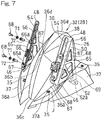
- Fig. 7 is a perspective view showing the outer covering segment 32 of the meter covering 28 as viewed from above in a forwardly downward direction.
- the outer covering segment 32 includes a front wall 36 for covering forwardly of the meter unit 26 and left and right connections 37 on left and right sides of the front wall 36.
- the left and right connections 37 are provided with respective pluralities of bolt insertion holes 37a.
- the outer covering segment 32 and the inner covering segment 34 (shown in Fig. 4 ) are connected together when the previously described bolt 35 is inserted from above into each of the bolt insertion holes 37a and is then threaded into a corresponding threaded hole (not shown) in the inner covering segment 34 (shown in Fig. 4 ).
- a bracket opening 46 is defined in the outer covering segment 32 between the front wall 36 and the left and right connections 37.
- the bracket opening 46 is in the form of a throughhole representing a slot elongated in the longitudinal direction.
- Shield brackets 48 for supporting the windshield 24 extend through the respective left and right bracket openings 46.
- the front wall 36 of the outer covering segment 32 is of a protruding shape that is bulged forwardly. More specifically, the front wall 36 has a forwardly bulged protruding shape forwardly bulged from opposite side end portions 36a and 36a towards an intermediate portion 36b.
- the front wall 36 includes a lower half portion 36f ranging from a lower end portion 36c to an intermediate portion 36d in the vertical direction and an upper half portion 36g ranging from the intermediate portion 36d to an upper end portion 36e.
- the lower half portion 36f extends substantially parallel to a rear surface 30 of the windshield 24 in a direction diagonally upwardly and rearwardly at an angle of inclination ⁇ relative to the horizontal plane H, whereas the upper half portion 36g extends inclined diagonally upwardly and rearwardly at an angle of inclination ⁇ so as to diverge from the windshield 24.
- angle of inclination ⁇ referred to above is so chosen as to be within the range of 65 to 75°, and in the practice of the preferred embodiment now under discussion about 70° is chosen therefor.
- angle of inclination ⁇ referred to above is so chosen as to be within the range of 25 to 35°, and in the practice of the preferred embodiment now under discussion, about 30° is chosen therefor.
- the outer covering segment 32 of the meter covering 28 is formed with an extension 38 which extends substantially horizontally rearwardly from the upper end portion 36e of the front wall 36 so as to cover the area above and adjacent to the meter unit 26.
- This extension 38 has a rear end 38a which is, when viewed from lateral side, positioned rearwardly of the rear end 24a of the windshield 24.
- the shield bracket 48 is formed from a metal sheet by the use of any known bending process and includes a shield fitting portion 50, positioned above the outer covering segment 32, and a to-be-supported portion 52 positioned beneath the outer covering segment 32.
- the to-be-supported portion 52 is formed with a bolt insertion hole 52a that is oriented in the vertical direction.
- the shield fitting portion 50 has a forwardly oriented fitting face 54.
- the fitting face 54 extends along the direction of inclination (diagonally rearwardly and upwardly) of the windshield 24, and a first slit 56 is formed in the fitting face 54.
- the first slit 56 referred to above is in the form of a throughhole having its direction of extension lying in a direction of extension of the fitting face 54. This first slit 56 extends in the vertical direction, when viewed from front as represented by Fig. 3 .
- the to-be-supported portion 52 of the shield bracket 48 which extends through the bracket opening 46, shown in Fig. 7 , in the vertical direction is connected with a fitting metal piece 58, provided in an upper end of the cowl stay 45, with the use of a bolt 60 as shown in Fig. 8 .
- the bolt 60 is inserted into the bolt insertion hole 52a (shown in Fig. 7 ) in the to-be-supported portion 52, and is then threaded into a threaded hole (not shown) in the fitting metal piece 58 to thereby connect the shield bracket 45 with the cowl stay 45.
- the meter covering 28 referred to previously is fitted to the front fairing 20 and the side fairing 25 by means of bolts 62 and 64 as shown in Fig. 2 .
- the bolt 62 is inserted into the bolt insertion hole 43 (shown in Fig. 4 ) in the inner covering segment 34 and is then threaded into a threaded hole (not shown) of the front fairing 20 and, at the same time, the bolt 64 is inserted into the bolt insertion hole 44 (shown in Fig 4 ) in the inner covering segment 34 and is threaded into a threaded hole (not shown) in the side fairing 25.
- the meter covering 28 is fitted to the front fairing 20 and the side fairing 25.
- the windshield 24 shown in Fig. 3 is positioned upwardly of the front fairing 20 and is fitted to the shield bracket 48.
- a slide member 65 is interposed between the windshield 24 and the shield bracket 48.
- the slide member 65 is in the form of a metal plate of a rectangular shape having its lengthwise direction lying in the direction of extension of the fitting face 54 of the shield bracket 48.
- the slide member 65 has opposite lengthwise ends which are bent rearwardly to provide respective guide pieces 67.
- the guide pieces 67 are guided along the first slit 56.
- the slide member 65 is so slidably set for movement along the shield bracket 48 in a direction substantially parallel to the lower half portion 36f of the front wall 36 so that the position of the slide member 65 relative to the shield bracket 48 can be properly fixed according to the size of the windshield 24.
- Opposite lengthwise end portions of the slide member 65 are formed with respective insertion holes 65a into which corresponding tubular nuts 72 each having a threaded hole are inserted.
- a bolt 68 is inserted into the bolt insertion hole 40 (shown in Fig. 5 ) in the windshield 24 through a washer 71 and is then threadingly engaged in the threaded hole of the corresponding tubular nut 72. Accordingly, the windshield 24 and the slide member 65 are sandwiched together by the bolt 68 and the tubular nut 72.
- a second slit 66 is formed between the two insertion holes 65a and 65a in the slide member 65. This second slit 66 is in the form of a throughhole of a slot shape extending in the lengthwise direction of the slide member 65.
- an adjustment screw 69 is inserted sequentially into the opening 42 in the windshield 24, then into the second slit 66 in the slide member 65 shown in Fig. 7 and finally into the first slit 56 in the shield bracket 48, and is fastened by a fastening member 70 (shown in Fig. 4 ) such as, for example, a bolt, from a rear face of the shield bracket 48.
- a fastening member 70 such as, for example, a bolt
- the adjustment screw 69 has to be first turned to become loose.
- the slide member 65 and the windshield 24 connected therewith can be brought into a condition ready to slide along the first slit 56 (shown in Fig. 7 ) in the shield bracket 48.
- the slide member 65 and the shield bracket 48 are fastened and fixed by means of the adjustment screw 69 and the fastening member 70 (shown in Fig. 4 ).
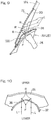
- Fig. 9 which shows a longitudinal sectional view, in the shape of the conventional front wall 100, sunlight L from the rear is impinged upon and is then reflected from the rear surface 30 of the windshield 24.
- the light R so reflected is subsequently focused on a focal point F of the meter covering 28. If the condition in which the reflected light R is kept focused on the focal point F for a prolonged length of time which would occur during, for example, parking, there is the possibility that the meter covering 28 would be adversely affected.
- the front wall 36 of the meter covering 28 is of the protruding shape bulged forwardly to allow the front wall 36 to deviate from the focal point F of the reflected light R from the windshield 24. Therefore, the reflected light R is never focused on one point of the meter covering 28, as shown in Figs. 9 and 10 . Accordingly, the adverse effect that the reflected light R from the windshield 24 would adversely affects the meter covering 28 can be suppressed.
- the front wall 36 of the meter covering 28 is so designed and so shaped as to depart from the focus point F of the reflected right R from the windshield 24 regardless of the position of the windshield 24 (noting that the double dotted line 124 employed in Fig. 9 represents the highest position of the windshield). Accordingly, it is possible to suppress the adverse effect brought about by the reflected light R on the meter covering 28.
- the meter covering 28 includes the extension 38 extending from the upper end portion 36e (shown in Fig. 8 ) of the front wall 36 in the rearward direction so as to cover the area above and adjacent to the meter unit 26, and the rear end 38a of the extension 38 is, when viewed from lateral side, positioned rearwardly of the rear end 24a of the windshield 24.
- the extension 38 is preferably downwardly inclined, when viewed from lateral side, at an angle within the range of 20 to 50° relative to the neighborhood of the upper end portion 36e of the front wall 36, and in the practice of the preferred embodiment as set forth above the angle of inclination of the extension 38 is chosen to be about 35°.
- the extension 38 in the manner described above, the possibility that the sunlight may be reflected from the meter display surface of the meter unit 26 to form a ghost on the windshield 24 can be avoided. Also, formation of a ghost of light of the meter unit 26 during the night can also be avoided.
- the front wall 36 is of the protruding shape having been bulged forwardly from the opposite end portions 36a and 36a towards the intermediate portion 36b while the lower half portion 36f extends along the rear surface 30 of the windshield 24 and, the upper half portion 36g extends having been inclined rearwardly so ad to depart from the windshield 24. Accordingly, owning to the upper end portion 36e of the meter covering 28, the possibility of the forward sight through the windshield 24 being disturbed can be avoided.
- the present invention has been fully described in connection with the preferred embodiments thereof with reference to the accompanying drawings which are used only for the purpose of illustration, the scope of protection being defined by the appended claims.
- the meter covering 28 has been shown and described as covering the area forwardly of, lateral side of and above the meter unit 26, the present invention may be applied to such case that at least an area forwardly of and adjacent to the meter unit 26 is covered by the meter covering 28.
- the windshield 24 has been shown and described as being slidable manually, it may be performed automatically, for example, by means of a motor.
- the saddle-riding vehicle referred to hereinabove has been shown and described as the motorcycle, the present invention can be equally applied even when the saddle-riding vehicle is a three or four-wheeled, irregular ground travelling vehicle.
Landscapes
- Engineering & Computer Science (AREA)
- Mechanical Engineering (AREA)
- Instrument Panels (AREA)
- Body Structure For Vehicles (AREA)
Applications Claiming Priority (2)
| Application Number | Priority Date | Filing Date | Title |
|---|---|---|---|
| JP2014086072A JP6357004B2 (ja) | 2014-04-18 | 2014-04-18 | 鞍乗型車両の前部構造 |
| PCT/JP2015/058162 WO2015159639A1 (ja) | 2014-04-18 | 2015-03-19 | 鞍乗型車両の前部構造 |
Publications (3)
| Publication Number | Publication Date |
|---|---|
| EP3133005A1 EP3133005A1 (en) | 2017-02-22 |
| EP3133005A4 EP3133005A4 (en) | 2018-01-17 |
| EP3133005B1 true EP3133005B1 (en) | 2021-04-28 |
Family
ID=54323853
Family Applications (1)
| Application Number | Title | Priority Date | Filing Date |
|---|---|---|---|
| EP15780262.0A Active EP3133005B1 (en) | 2014-04-18 | 2015-03-19 | Structure for front part of saddled vehicle |
Country Status (4)
| Country | Link |
|---|---|
| US (1) | US10189526B2 (enExample) |
| EP (1) | EP3133005B1 (enExample) |
| JP (1) | JP6357004B2 (enExample) |
| WO (1) | WO2015159639A1 (enExample) |
Families Citing this family (8)
| Publication number | Priority date | Publication date | Assignee | Title |
|---|---|---|---|---|
| JP6129884B2 (ja) * | 2015-01-23 | 2017-05-17 | 本田技研工業株式会社 | 鞍乗り型車両のサイドカバー構造 |
| JP6298485B2 (ja) * | 2016-03-18 | 2018-03-20 | 本田技研工業株式会社 | 鞍乗り型車両の風防装置 |
| CN107554657B (zh) * | 2017-09-22 | 2023-09-22 | 重庆隆鑫机车有限公司 | 挡风罩总成及其摩托车 |
| JP7026075B2 (ja) * | 2019-03-25 | 2022-02-25 | 株式会社ニフコ | 鞍乗り型車両の風防装置 |
| JP7433167B2 (ja) * | 2020-08-21 | 2024-02-19 | カワサキモータース株式会社 | 鞍乗型乗物 |
| JP2022155869A (ja) * | 2021-03-31 | 2022-10-14 | ヤマハ発動機株式会社 | 鞍乗型車両 |
| JP7661387B2 (ja) | 2023-03-16 | 2025-04-14 | 本田技研工業株式会社 | 鞍乗り型車両のカウル構造 |
| JP2025167591A (ja) * | 2024-04-26 | 2025-11-07 | ヤマハ発動機株式会社 | 鞍乗型車両 |
Family Cites Families (12)
| Publication number | Priority date | Publication date | Assignee | Title |
|---|---|---|---|---|
| JPS5225344A (en) * | 1975-08-15 | 1977-02-25 | Honda Motor Co Ltd | Hood unit for motor cycle |
| JP2531687Y2 (ja) * | 1990-11-27 | 1997-04-09 | 能美防災株式会社 | 減光式煙感知器 |
| JP2001278153A (ja) * | 2000-04-03 | 2001-10-10 | Honda Motor Co Ltd | 自動二輪車用ヘッドアップディスプレイ装置 |
| JP4090717B2 (ja) * | 2001-09-11 | 2008-05-28 | 本田技研工業株式会社 | 自動二輪車 |
| JP4388295B2 (ja) * | 2003-03-25 | 2009-12-24 | 川崎重工業株式会社 | ウインドスクリーン |
| JP5095250B2 (ja) * | 2007-03-30 | 2012-12-12 | 本田技研工業株式会社 | 自動二輪車の風防制御装置 |
| JP4952622B2 (ja) * | 2008-03-11 | 2012-06-13 | 本田技研工業株式会社 | 自動二輪車のスクリーン装置 |
| JP2013091387A (ja) | 2011-10-25 | 2013-05-16 | Kawasaki Heavy Ind Ltd | 乗物のウインドシールド取付構造 |
| JP5988639B2 (ja) * | 2012-03-22 | 2016-09-07 | 本田技研工業株式会社 | 鞍乗り型車両の導風構造 |
| JP5937460B2 (ja) * | 2012-08-27 | 2016-06-22 | 本田技研工業株式会社 | 鞍乗り型車両の携帯端末収納構造 |
| JP6101452B2 (ja) * | 2012-08-31 | 2017-03-22 | 本田技研工業株式会社 | 鞍乗型車両のヘッドライト支持構造 |
| JP2015058162A (ja) | 2013-09-19 | 2015-03-30 | 株式会社東芝 | 接触検出装置及び医用画像診断装置 |
-
2014
- 2014-04-18 JP JP2014086072A patent/JP6357004B2/ja active Active
-
2015
- 2015-03-19 WO PCT/JP2015/058162 patent/WO2015159639A1/ja not_active Ceased
- 2015-03-19 EP EP15780262.0A patent/EP3133005B1/en active Active
-
2016
- 2016-10-05 US US15/286,420 patent/US10189526B2/en active Active
Non-Patent Citations (1)
| Title |
|---|
| None * |
Also Published As
| Publication number | Publication date |
|---|---|
| JP6357004B2 (ja) | 2018-07-11 |
| WO2015159639A1 (ja) | 2015-10-22 |
| US10189526B2 (en) | 2019-01-29 |
| EP3133005A4 (en) | 2018-01-17 |
| US20170021887A1 (en) | 2017-01-26 |
| JP2015205548A (ja) | 2015-11-19 |
| EP3133005A1 (en) | 2017-02-22 |
Similar Documents
| Publication | Publication Date | Title |
|---|---|---|
| EP3133005B1 (en) | Structure for front part of saddled vehicle | |
| US9296420B2 (en) | Vehicle | |
| EP3476708B1 (en) | Optical sensor supporting structure for saddled vehicles | |
| EP2468613B1 (en) | Vehicle handlebar support structure | |
| US9764789B2 (en) | Side cover structure of saddle-ride-type vehicle | |
| US20170267304A1 (en) | Windshield device for saddle-ride type vehicle | |
| JP2019500271A5 (enExample) | ||
| US7178858B1 (en) | Deflector assembly for motorcycle | |
| US20140167452A1 (en) | Motorcycle rear body structure | |
| EP2168856B1 (en) | Vehicle front structure | |
| US9061727B2 (en) | Frame structure for a saddle-ride type vehicle, and vehicle incorporating the same | |
| US9616957B2 (en) | Motorcycle fairing adjustment member and assembly and method of adjusting a motorcycle fairing | |
| JP5210939B2 (ja) | 鞍乗り型車両 | |
| EP2876027B1 (en) | Saddle-ride type vehicle | |
| CN103010350A (zh) | 车辆的前部结构 | |
| EP2168855B1 (en) | Vehicle front structure | |
| EP2077218A2 (en) | Front fender and motorcycle | |
| US11964724B2 (en) | Fixing structure of screen | |
| DE202024101271U1 (de) | Fahrzeugstruktur eines Sattelfahrtyp-Fahrzeugs | |
| JP2012183898A (ja) | 鞍乗り型車両 | |
| EP3002192A1 (en) | Straddled vehicle | |
| TH1901005183A (th) | ยานพาหนะชนิดมีอาน | |
| EP3305641A1 (en) | Straddled vehicle | |
| CN113264119A (zh) | 车辆挡泥板 | |
| TH94539A (th) | โครงสร้างชิ้นปิดครอบตัวถังด้านหน้าสำหรับจักรยานยนต์ |
Legal Events
| Date | Code | Title | Description |
|---|---|---|---|
| STAA | Information on the status of an ep patent application or granted ep patent |
Free format text: STATUS: THE INTERNATIONAL PUBLICATION HAS BEEN MADE |
|
| PUAI | Public reference made under article 153(3) epc to a published international application that has entered the european phase |
Free format text: ORIGINAL CODE: 0009012 |
|
| STAA | Information on the status of an ep patent application or granted ep patent |
Free format text: STATUS: REQUEST FOR EXAMINATION WAS MADE |
|
| 17P | Request for examination filed |
Effective date: 20161102 |
|
| AK | Designated contracting states |
Kind code of ref document: A1 Designated state(s): AL AT BE BG CH CY CZ DE DK EE ES FI FR GB GR HR HU IE IS IT LI LT LU LV MC MK MT NL NO PL PT RO RS SE SI SK SM TR |
|
| AX | Request for extension of the european patent |
Extension state: BA ME |
|
| DAV | Request for validation of the european patent (deleted) | ||
| DAX | Request for extension of the european patent (deleted) | ||
| A4 | Supplementary search report drawn up and despatched |
Effective date: 20171214 |
|
| RIC1 | Information provided on ipc code assigned before grant |
Ipc: B62J 99/00 20090101ALI20171208BHEP Ipc: B62J 17/04 20060101AFI20171208BHEP |
|
| STAA | Information on the status of an ep patent application or granted ep patent |
Free format text: STATUS: EXAMINATION IS IN PROGRESS |
|
| 17Q | First examination report despatched |
Effective date: 20180905 |
|
| GRAP | Despatch of communication of intention to grant a patent |
Free format text: ORIGINAL CODE: EPIDOSNIGR1 |
|
| STAA | Information on the status of an ep patent application or granted ep patent |
Free format text: STATUS: GRANT OF PATENT IS INTENDED |
|
| INTG | Intention to grant announced |
Effective date: 20201211 |
|
| GRAS | Grant fee paid |
Free format text: ORIGINAL CODE: EPIDOSNIGR3 |
|
| GRAA | (expected) grant |
Free format text: ORIGINAL CODE: 0009210 |
|
| STAA | Information on the status of an ep patent application or granted ep patent |
Free format text: STATUS: THE PATENT HAS BEEN GRANTED |
|
| AK | Designated contracting states |
Kind code of ref document: B1 Designated state(s): AL AT BE BG CH CY CZ DE DK EE ES FI FR GB GR HR HU IE IS IT LI LT LU LV MC MK MT NL NO PL PT RO RS SE SI SK SM TR |
|
| REG | Reference to a national code |
Ref country code: GB Ref legal event code: FG4D |
|
| REG | Reference to a national code |
Ref country code: CH Ref legal event code: EP |
|
| REG | Reference to a national code |
Ref country code: DE Ref legal event code: R096 Ref document number: 602015068704 Country of ref document: DE |
|
| REG | Reference to a national code |
Ref country code: AT Ref legal event code: REF Ref document number: 1386773 Country of ref document: AT Kind code of ref document: T Effective date: 20210515 |
|
| REG | Reference to a national code |
Ref country code: IE Ref legal event code: FG4D |
|
| REG | Reference to a national code |
Ref country code: LT Ref legal event code: MG9D |
|
| REG | Reference to a national code |
Ref country code: AT Ref legal event code: MK05 Ref document number: 1386773 Country of ref document: AT Kind code of ref document: T Effective date: 20210428 |
|
| PG25 | Lapsed in a contracting state [announced via postgrant information from national office to epo] |
Ref country code: FI Free format text: LAPSE BECAUSE OF FAILURE TO SUBMIT A TRANSLATION OF THE DESCRIPTION OR TO PAY THE FEE WITHIN THE PRESCRIBED TIME-LIMIT Effective date: 20210428 Ref country code: LT Free format text: LAPSE BECAUSE OF FAILURE TO SUBMIT A TRANSLATION OF THE DESCRIPTION OR TO PAY THE FEE WITHIN THE PRESCRIBED TIME-LIMIT Effective date: 20210428 Ref country code: NL Free format text: LAPSE BECAUSE OF FAILURE TO SUBMIT A TRANSLATION OF THE DESCRIPTION OR TO PAY THE FEE WITHIN THE PRESCRIBED TIME-LIMIT Effective date: 20210428 Ref country code: AT Free format text: LAPSE BECAUSE OF FAILURE TO SUBMIT A TRANSLATION OF THE DESCRIPTION OR TO PAY THE FEE WITHIN THE PRESCRIBED TIME-LIMIT Effective date: 20210428 Ref country code: BG Free format text: LAPSE BECAUSE OF FAILURE TO SUBMIT A TRANSLATION OF THE DESCRIPTION OR TO PAY THE FEE WITHIN THE PRESCRIBED TIME-LIMIT Effective date: 20210728 Ref country code: HR Free format text: LAPSE BECAUSE OF FAILURE TO SUBMIT A TRANSLATION OF THE DESCRIPTION OR TO PAY THE FEE WITHIN THE PRESCRIBED TIME-LIMIT Effective date: 20210428 |
|
| PG25 | Lapsed in a contracting state [announced via postgrant information from national office to epo] |
Ref country code: GR Free format text: LAPSE BECAUSE OF FAILURE TO SUBMIT A TRANSLATION OF THE DESCRIPTION OR TO PAY THE FEE WITHIN THE PRESCRIBED TIME-LIMIT Effective date: 20210729 Ref country code: LV Free format text: LAPSE BECAUSE OF FAILURE TO SUBMIT A TRANSLATION OF THE DESCRIPTION OR TO PAY THE FEE WITHIN THE PRESCRIBED TIME-LIMIT Effective date: 20210428 Ref country code: IS Free format text: LAPSE BECAUSE OF FAILURE TO SUBMIT A TRANSLATION OF THE DESCRIPTION OR TO PAY THE FEE WITHIN THE PRESCRIBED TIME-LIMIT Effective date: 20210828 Ref country code: RS Free format text: LAPSE BECAUSE OF FAILURE TO SUBMIT A TRANSLATION OF THE DESCRIPTION OR TO PAY THE FEE WITHIN THE PRESCRIBED TIME-LIMIT Effective date: 20210428 Ref country code: SE Free format text: LAPSE BECAUSE OF FAILURE TO SUBMIT A TRANSLATION OF THE DESCRIPTION OR TO PAY THE FEE WITHIN THE PRESCRIBED TIME-LIMIT Effective date: 20210428 Ref country code: ES Free format text: LAPSE BECAUSE OF FAILURE TO SUBMIT A TRANSLATION OF THE DESCRIPTION OR TO PAY THE FEE WITHIN THE PRESCRIBED TIME-LIMIT Effective date: 20210428 Ref country code: NO Free format text: LAPSE BECAUSE OF FAILURE TO SUBMIT A TRANSLATION OF THE DESCRIPTION OR TO PAY THE FEE WITHIN THE PRESCRIBED TIME-LIMIT Effective date: 20210728 Ref country code: PL Free format text: LAPSE BECAUSE OF FAILURE TO SUBMIT A TRANSLATION OF THE DESCRIPTION OR TO PAY THE FEE WITHIN THE PRESCRIBED TIME-LIMIT Effective date: 20210428 Ref country code: PT Free format text: LAPSE BECAUSE OF FAILURE TO SUBMIT A TRANSLATION OF THE DESCRIPTION OR TO PAY THE FEE WITHIN THE PRESCRIBED TIME-LIMIT Effective date: 20210830 |
|
| REG | Reference to a national code |
Ref country code: NL Ref legal event code: MP Effective date: 20210428 |
|
| PG25 | Lapsed in a contracting state [announced via postgrant information from national office to epo] |
Ref country code: CZ Free format text: LAPSE BECAUSE OF FAILURE TO SUBMIT A TRANSLATION OF THE DESCRIPTION OR TO PAY THE FEE WITHIN THE PRESCRIBED TIME-LIMIT Effective date: 20210428 Ref country code: DK Free format text: LAPSE BECAUSE OF FAILURE TO SUBMIT A TRANSLATION OF THE DESCRIPTION OR TO PAY THE FEE WITHIN THE PRESCRIBED TIME-LIMIT Effective date: 20210428 Ref country code: EE Free format text: LAPSE BECAUSE OF FAILURE TO SUBMIT A TRANSLATION OF THE DESCRIPTION OR TO PAY THE FEE WITHIN THE PRESCRIBED TIME-LIMIT Effective date: 20210428 Ref country code: SK Free format text: LAPSE BECAUSE OF FAILURE TO SUBMIT A TRANSLATION OF THE DESCRIPTION OR TO PAY THE FEE WITHIN THE PRESCRIBED TIME-LIMIT Effective date: 20210428 Ref country code: SM Free format text: LAPSE BECAUSE OF FAILURE TO SUBMIT A TRANSLATION OF THE DESCRIPTION OR TO PAY THE FEE WITHIN THE PRESCRIBED TIME-LIMIT Effective date: 20210428 Ref country code: RO Free format text: LAPSE BECAUSE OF FAILURE TO SUBMIT A TRANSLATION OF THE DESCRIPTION OR TO PAY THE FEE WITHIN THE PRESCRIBED TIME-LIMIT Effective date: 20210428 |
|
| REG | Reference to a national code |
Ref country code: DE Ref legal event code: R097 Ref document number: 602015068704 Country of ref document: DE |
|
| PLBE | No opposition filed within time limit |
Free format text: ORIGINAL CODE: 0009261 |
|
| STAA | Information on the status of an ep patent application or granted ep patent |
Free format text: STATUS: NO OPPOSITION FILED WITHIN TIME LIMIT |
|
| 26N | No opposition filed |
Effective date: 20220131 |
|
| REG | Reference to a national code |
Ref country code: DE Ref legal event code: R081 Ref document number: 602015068704 Country of ref document: DE Owner name: KAWASAKI MOTORS, LTD., AKASHI-SHI, JP Free format text: FORMER OWNER: KAWASAKI JUKOGYO KABUSHIKI KAISHA, KOBE-SHI, HYOGO, JP |
|
| PG25 | Lapsed in a contracting state [announced via postgrant information from national office to epo] |
Ref country code: IS Free format text: LAPSE BECAUSE OF FAILURE TO SUBMIT A TRANSLATION OF THE DESCRIPTION OR TO PAY THE FEE WITHIN THE PRESCRIBED TIME-LIMIT Effective date: 20210828 Ref country code: AL Free format text: LAPSE BECAUSE OF FAILURE TO SUBMIT A TRANSLATION OF THE DESCRIPTION OR TO PAY THE FEE WITHIN THE PRESCRIBED TIME-LIMIT Effective date: 20210428 |
|
| PG25 | Lapsed in a contracting state [announced via postgrant information from national office to epo] |
Ref country code: IT Free format text: LAPSE BECAUSE OF FAILURE TO SUBMIT A TRANSLATION OF THE DESCRIPTION OR TO PAY THE FEE WITHIN THE PRESCRIBED TIME-LIMIT Effective date: 20210428 |
|
| PG25 | Lapsed in a contracting state [announced via postgrant information from national office to epo] |
Ref country code: MC Free format text: LAPSE BECAUSE OF FAILURE TO SUBMIT A TRANSLATION OF THE DESCRIPTION OR TO PAY THE FEE WITHIN THE PRESCRIBED TIME-LIMIT Effective date: 20210428 |
|
| REG | Reference to a national code |
Ref country code: CH Ref legal event code: PL |
|
| GBPC | Gb: european patent ceased through non-payment of renewal fee |
Effective date: 20220319 |
|
| REG | Reference to a national code |
Ref country code: BE Ref legal event code: MM Effective date: 20220331 |
|
| PG25 | Lapsed in a contracting state [announced via postgrant information from national office to epo] |
Ref country code: LI Free format text: LAPSE BECAUSE OF NON-PAYMENT OF DUE FEES Effective date: 20220331 Ref country code: IE Free format text: LAPSE BECAUSE OF NON-PAYMENT OF DUE FEES Effective date: 20220319 Ref country code: GB Free format text: LAPSE BECAUSE OF NON-PAYMENT OF DUE FEES Effective date: 20220319 Ref country code: FR Free format text: LAPSE BECAUSE OF NON-PAYMENT OF DUE FEES Effective date: 20220331 Ref country code: CH Free format text: LAPSE BECAUSE OF NON-PAYMENT OF DUE FEES Effective date: 20220331 Ref country code: LU Free format text: LAPSE BECAUSE OF NON-PAYMENT OF DUE FEES Effective date: 20220319 |
|
| PG25 | Lapsed in a contracting state [announced via postgrant information from national office to epo] |
Ref country code: BE Free format text: LAPSE BECAUSE OF NON-PAYMENT OF DUE FEES Effective date: 20220331 |
|
| PG25 | Lapsed in a contracting state [announced via postgrant information from national office to epo] |
Ref country code: HU Free format text: LAPSE BECAUSE OF FAILURE TO SUBMIT A TRANSLATION OF THE DESCRIPTION OR TO PAY THE FEE WITHIN THE PRESCRIBED TIME-LIMIT; INVALID AB INITIO Effective date: 20150319 |
|
| PG25 | Lapsed in a contracting state [announced via postgrant information from national office to epo] |
Ref country code: MK Free format text: LAPSE BECAUSE OF FAILURE TO SUBMIT A TRANSLATION OF THE DESCRIPTION OR TO PAY THE FEE WITHIN THE PRESCRIBED TIME-LIMIT Effective date: 20210428 Ref country code: CY Free format text: LAPSE BECAUSE OF FAILURE TO SUBMIT A TRANSLATION OF THE DESCRIPTION OR TO PAY THE FEE WITHIN THE PRESCRIBED TIME-LIMIT Effective date: 20210428 |
|
| PG25 | Lapsed in a contracting state [announced via postgrant information from national office to epo] |
Ref country code: MT Free format text: LAPSE BECAUSE OF FAILURE TO SUBMIT A TRANSLATION OF THE DESCRIPTION OR TO PAY THE FEE WITHIN THE PRESCRIBED TIME-LIMIT Effective date: 20210428 |
|
| PG25 | Lapsed in a contracting state [announced via postgrant information from national office to epo] |
Ref country code: TR Free format text: LAPSE BECAUSE OF FAILURE TO SUBMIT A TRANSLATION OF THE DESCRIPTION OR TO PAY THE FEE WITHIN THE PRESCRIBED TIME-LIMIT Effective date: 20210428 |
|
| PGFP | Annual fee paid to national office [announced via postgrant information from national office to epo] |
Ref country code: DE Payment date: 20260128 Year of fee payment: 12 |