EP3132913B1 - Einstellbarer kühlring zur dickensteuerung - Google Patents
Einstellbarer kühlring zur dickensteuerung Download PDFInfo
- Publication number
- EP3132913B1 EP3132913B1 EP15779799.4A EP15779799A EP3132913B1 EP 3132913 B1 EP3132913 B1 EP 3132913B1 EP 15779799 A EP15779799 A EP 15779799A EP 3132913 B1 EP3132913 B1 EP 3132913B1
- Authority
- EP
- European Patent Office
- Prior art keywords
- ring
- synthetic resin
- thickness variation
- cooling air
- passage
- Prior art date
- Legal status (The legal status is an assumption and is not a legal conclusion. Google has not performed a legal analysis and makes no representation as to the accuracy of the status listed.)
- Revoked
Links
Images


Classifications
-
- B—PERFORMING OPERATIONS; TRANSPORTING
- B29—WORKING OF PLASTICS; WORKING OF SUBSTANCES IN A PLASTIC STATE IN GENERAL
- B29C—SHAPING OR JOINING OF PLASTICS; SHAPING OF MATERIAL IN A PLASTIC STATE, NOT OTHERWISE PROVIDED FOR; AFTER-TREATMENT OF THE SHAPED PRODUCTS, e.g. REPAIRING
- B29C48/00—Extrusion moulding, i.e. expressing the moulding material through a die or nozzle which imparts the desired form; Apparatus therefor
- B29C48/25—Component parts, details or accessories; Auxiliary operations
- B29C48/88—Thermal treatment of the stream of extruded material, e.g. cooling
- B29C48/885—External treatment, e.g. by using air rings for cooling tubular films
-
- B—PERFORMING OPERATIONS; TRANSPORTING
- B29—WORKING OF PLASTICS; WORKING OF SUBSTANCES IN A PLASTIC STATE IN GENERAL
- B29C—SHAPING OR JOINING OF PLASTICS; SHAPING OF MATERIAL IN A PLASTIC STATE, NOT OTHERWISE PROVIDED FOR; AFTER-TREATMENT OF THE SHAPED PRODUCTS, e.g. REPAIRING
- B29C48/00—Extrusion moulding, i.e. expressing the moulding material through a die or nozzle which imparts the desired form; Apparatus therefor
- B29C48/03—Extrusion moulding, i.e. expressing the moulding material through a die or nozzle which imparts the desired form; Apparatus therefor characterised by the shape of the extruded material at extrusion
- B29C48/09—Articles with cross-sections having partially or fully enclosed cavities, e.g. pipes or channels
- B29C48/10—Articles with cross-sections having partially or fully enclosed cavities, e.g. pipes or channels flexible, e.g. blown foils
-
- B—PERFORMING OPERATIONS; TRANSPORTING
- B29—WORKING OF PLASTICS; WORKING OF SUBSTANCES IN A PLASTIC STATE IN GENERAL
- B29C—SHAPING OR JOINING OF PLASTICS; SHAPING OF MATERIAL IN A PLASTIC STATE, NOT OTHERWISE PROVIDED FOR; AFTER-TREATMENT OF THE SHAPED PRODUCTS, e.g. REPAIRING
- B29C48/00—Extrusion moulding, i.e. expressing the moulding material through a die or nozzle which imparts the desired form; Apparatus therefor
- B29C48/25—Component parts, details or accessories; Auxiliary operations
- B29C48/30—Extrusion nozzles or dies
- B29C48/32—Extrusion nozzles or dies with annular openings, e.g. for forming tubular articles
-
- B—PERFORMING OPERATIONS; TRANSPORTING
- B29—WORKING OF PLASTICS; WORKING OF SUBSTANCES IN A PLASTIC STATE IN GENERAL
- B29C—SHAPING OR JOINING OF PLASTICS; SHAPING OF MATERIAL IN A PLASTIC STATE, NOT OTHERWISE PROVIDED FOR; AFTER-TREATMENT OF THE SHAPED PRODUCTS, e.g. REPAIRING
- B29C48/00—Extrusion moulding, i.e. expressing the moulding material through a die or nozzle which imparts the desired form; Apparatus therefor
- B29C48/25—Component parts, details or accessories; Auxiliary operations
- B29C48/88—Thermal treatment of the stream of extruded material, e.g. cooling
- B29C48/911—Cooling
- B29C48/9115—Cooling of hollow articles
- B29C48/912—Cooling of hollow articles of tubular films
-
- B—PERFORMING OPERATIONS; TRANSPORTING
- B29—WORKING OF PLASTICS; WORKING OF SUBSTANCES IN A PLASTIC STATE IN GENERAL
- B29C—SHAPING OR JOINING OF PLASTICS; SHAPING OF MATERIAL IN A PLASTIC STATE, NOT OTHERWISE PROVIDED FOR; AFTER-TREATMENT OF THE SHAPED PRODUCTS, e.g. REPAIRING
- B29C48/00—Extrusion moulding, i.e. expressing the moulding material through a die or nozzle which imparts the desired form; Apparatus therefor
- B29C48/25—Component parts, details or accessories; Auxiliary operations
- B29C48/92—Measuring, controlling or regulating
-
- B—PERFORMING OPERATIONS; TRANSPORTING
- B29—WORKING OF PLASTICS; WORKING OF SUBSTANCES IN A PLASTIC STATE IN GENERAL
- B29C—SHAPING OR JOINING OF PLASTICS; SHAPING OF MATERIAL IN A PLASTIC STATE, NOT OTHERWISE PROVIDED FOR; AFTER-TREATMENT OF THE SHAPED PRODUCTS, e.g. REPAIRING
- B29C55/00—Shaping by stretching, e.g. drawing through a die; Apparatus therefor
- B29C55/28—Shaping by stretching, e.g. drawing through a die; Apparatus therefor of blown tubular films, e.g. by inflation
-
- B—PERFORMING OPERATIONS; TRANSPORTING
- B29—WORKING OF PLASTICS; WORKING OF SUBSTANCES IN A PLASTIC STATE IN GENERAL
- B29C—SHAPING OR JOINING OF PLASTICS; SHAPING OF MATERIAL IN A PLASTIC STATE, NOT OTHERWISE PROVIDED FOR; AFTER-TREATMENT OF THE SHAPED PRODUCTS, e.g. REPAIRING
- B29C2948/00—Indexing scheme relating to extrusion moulding
- B29C2948/92—Measuring, controlling or regulating
- B29C2948/92009—Measured parameter
- B29C2948/92114—Dimensions
- B29C2948/92152—Thickness
-
- B—PERFORMING OPERATIONS; TRANSPORTING
- B29—WORKING OF PLASTICS; WORKING OF SUBSTANCES IN A PLASTIC STATE IN GENERAL
- B29C—SHAPING OR JOINING OF PLASTICS; SHAPING OF MATERIAL IN A PLASTIC STATE, NOT OTHERWISE PROVIDED FOR; AFTER-TREATMENT OF THE SHAPED PRODUCTS, e.g. REPAIRING
- B29C2948/00—Indexing scheme relating to extrusion moulding
- B29C2948/92—Measuring, controlling or regulating
- B29C2948/92323—Location or phase of measurement
- B29C2948/92447—Moulded article
-
- B—PERFORMING OPERATIONS; TRANSPORTING
- B29—WORKING OF PLASTICS; WORKING OF SUBSTANCES IN A PLASTIC STATE IN GENERAL
- B29C—SHAPING OR JOINING OF PLASTICS; SHAPING OF MATERIAL IN A PLASTIC STATE, NOT OTHERWISE PROVIDED FOR; AFTER-TREATMENT OF THE SHAPED PRODUCTS, e.g. REPAIRING
- B29C2948/00—Indexing scheme relating to extrusion moulding
- B29C2948/92—Measuring, controlling or regulating
- B29C2948/92504—Controlled parameter
- B29C2948/9258—Velocity
- B29C2948/926—Flow or feed rate
-
- B—PERFORMING OPERATIONS; TRANSPORTING
- B29—WORKING OF PLASTICS; WORKING OF SUBSTANCES IN A PLASTIC STATE IN GENERAL
- B29C—SHAPING OR JOINING OF PLASTICS; SHAPING OF MATERIAL IN A PLASTIC STATE, NOT OTHERWISE PROVIDED FOR; AFTER-TREATMENT OF THE SHAPED PRODUCTS, e.g. REPAIRING
- B29C2948/00—Indexing scheme relating to extrusion moulding
- B29C2948/92—Measuring, controlling or regulating
- B29C2948/92504—Controlled parameter
- B29C2948/92609—Dimensions
- B29C2948/92657—Volume or quantity
-
- B—PERFORMING OPERATIONS; TRANSPORTING
- B29—WORKING OF PLASTICS; WORKING OF SUBSTANCES IN A PLASTIC STATE IN GENERAL
- B29C—SHAPING OR JOINING OF PLASTICS; SHAPING OF MATERIAL IN A PLASTIC STATE, NOT OTHERWISE PROVIDED FOR; AFTER-TREATMENT OF THE SHAPED PRODUCTS, e.g. REPAIRING
- B29C2948/00—Indexing scheme relating to extrusion moulding
- B29C2948/92—Measuring, controlling or regulating
- B29C2948/92819—Location or phase of control
- B29C2948/92971—Fluids, e.g. for temperature control or of environment
-
- B—PERFORMING OPERATIONS; TRANSPORTING
- B29—WORKING OF PLASTICS; WORKING OF SUBSTANCES IN A PLASTIC STATE IN GENERAL
- B29K—INDEXING SCHEME ASSOCIATED WITH SUBCLASSES B29B, B29C OR B29D, RELATING TO MOULDING MATERIALS OR TO MATERIALS FOR MOULDS, REINFORCEMENTS, FILLERS OR PREFORMED PARTS, e.g. INSERTS
- B29K2105/00—Condition, form or state of moulded material or of the material to be shaped
- B29K2105/0058—Liquid or visquous
- B29K2105/0067—Melt
-
- B—PERFORMING OPERATIONS; TRANSPORTING
- B29—WORKING OF PLASTICS; WORKING OF SUBSTANCES IN A PLASTIC STATE IN GENERAL
- B29L—INDEXING SCHEME ASSOCIATED WITH SUBCLASS B29C, RELATING TO PARTICULAR ARTICLES
- B29L2023/00—Tubular articles
- B29L2023/001—Tubular films, sleeves
Definitions
- the present invention relates to a thickness variation adjustment-type air ring which is provided on a die of an inflation film manufacturing apparatus that forms a synthetic resin film so as to locally control the volume of cooling air in a circumferential direction in order to adjust the thickness variation (thickness unevenness) of a synthetic resin film when blowing the said cooling air around an extruded molten synthetic resin tube to cool and solidify the molten synthetic resin tube to form the synthetic resin film.
- a general inflation film manufacturing apparatus forms a synthetic resin film by cooling and solidifying a molten synthetic resin tube extruded from a die slit (for example, see Patent Document 1).
- the inflation film manufacturing apparatus of Patent Document 1 includes a die head having a ring nozzle, an outer blowing nozzle and a measurement device for measuring the film thickness of tube-shaped film. The volume of air flow passing through the nozzles of the ring of the air nozzle group is controlled based on the measurement results of the measurement device.
- FIGS. 9 to 11 An air ring illustrated in FIGS. 9 to 11 , for example, is known as an example of an air ring used in this type of inflation film manufacturing apparatus.
- a number of block-shaped slope members are arranged in a ring form in a cooling air passage inside of an air ring 100.
- the slope members 101 are moved in a radial direction by a moving portion 107 such as a motor, to locally change the gap of passages 103 formed between the slope members 101 and a blow out ring 102.
- reference numeral 105 indicates a hose opening, through which cooling air 106 from a blower (not illustrated) is introduced via a hose (not illustrated) connected to the hose opening 105.
- the hose opening 105 has four hose openings separated at a predetermined interval in the circumferential direction.
- EP 1 004 424 A1 describes an air ring for cooling blown plastic film.
- the air ring comprises an annular body with a circumferentially extending air passage. Further the air ring comprises a circumferentially extending series of individually operable actuators each operable to vary the flow of cooling air. To vary the thickness of a film a flap member can be moved to restrict the air flow and a resilient flap member can be moved.
- US 5, 676, 893 A a method for controlling cooling of a circular extrudate is described.
- the extrudate comprises a plurality of circumferentially arranged air cooling flow control devices. Each of these devices is adjustable for varying the volumetric flow. External cooling is done by a cooling ring with associated cooling lips.
- the thickness control system comprises an inlet for receiving air, lips, radially oriented channels arranged in a first plane for directing air inwardly from the inlet to the lips, and a plurality of movable barriers.
- the plurality of barriers is movable along a direction perpendicular to the first plane of radially oriented channels.
- a thickness control system is shown, which comprises an inlet for receiving air, lips for providing air to an external surface of the blown film, an annular region arranged in a first plane for providing air inwardly from the inlet to the lips and a plurality of radially oriented blocks.
- the plurality of blocks is movable along a direction perpendicular to the first plane of the annular region for controlling a cross section of air flow.
- DE 37 43 720 A1 describes a film blowing apparatus with a die head on which a cooling ring is disposed.
- the cooling ring comprises an elastic upper disc and/or a lower disc. The distance between the discs can be adjusted.
- the upper disk is in contact with a plurality of actuators. A exit gap of the upper and lower disks is located on the inner surface of the ring.
- GB 854 368 A shows a process and an apparatus for producing of seamless tubing.
- the apparatus comprises a die having an annular extrusion orifice, means for extruding a hot thermoplastic material, means for inflating and means for directing cooling gas.
- the means for directing cooling gas comprise an annular supply chamber having an opening.
- the supply chamber is continually rotated by means.
- the supply chamber comprises upper and lower annular members or rings with baffles.
- the apparatus further comprises means for adjusting the dimension of the discharge passage.
- a passage wall consist of a flexible annular member supported on a number of studs. One part of the flexible member may be raised and another lowered so as to obtain any desired pattern of flow of the cooling fluid.
- the bevelled upper surface of the flexible member is parallel to a bevelled adjacent surface of the upper ring.
- a blow out opening consists of the upper surface of the flexible member and the surface of the upper ring.
- JP S54 64173 U discloses a cooling ring having a ring-shaped elastic member which is attached to ring-shaped steps of an upper lip attached metallic material by ring-shaped pressure plates.
- the ring-shaped pressure plates are located on inner and outer edges of the ring-shaped elastic member, and fixed to the upper lip attached metallic material by bolts.
- Bolts for deforming the elastic member are located in a recess between the ring-shaped steps.
- Patent Document 1 Japanese Unexamined Patent Application, Publication No. H5-269844
- the respective slope members 101 may block each other' s way and may not move toward the inner side of the radial direction from their positions. Moreover, even if it is set so that there be no gap 108 between each slope member 101 on the inner side of the radial direction, although the slope members 101 will still be able to move toward the outer side in the radial direction, the gap 108 will be formed when the slope members move toward the outer side of the radial direction.
- the flow of cooling air is disturbed as indicated by flow lines 109 in FIG. 9 .
- the cooling air flowing through portions other than the gap 108 is controlled by each of the slope members 101, the cooling air, flowing through the gap 108, flows regardless of the gap of the passage 103 formed by the slope members 101, and for this reason it is not possible to control the cooling air flowing through the gap 108. Since the thickness variation of a synthetic resin film depends on the flow conditions such as the volume of cooling air, the problem of having parts of the synthetic resin film whose thickness variation is not possible to control, occurs.
- the objective of the present invention is to provide a thickness variation adjustment-type air ring capable of accurately and optimally controlling the volume of cooling air at all positions in the circumferential direction and stably manufacturing a synthetic resin film having an exceptionally low thickness variation.
- the present invention provides a thickness variation adjustment-type air ring which is provided on a die of an inflation film manufacturing apparatus and which locally controls the volume of cooling air discharged from a cooling air passage in a circumferential direction to adjust the thickness variation of a synthetic resin film when blowing the said cooling air around a molten synthetic resin tube extruded in a longitudinal direction to cool and solidify the molten synthetic resin tube to form the synthetic resin film
- the thickness variation adjustment-type air ring comprising: a ring-shaped passage adjustment portion arranged sequentially inside the cooling air passage in the circumferential direction; and a plurality of moving portions connected at a predetermined position in the circumferential direction of the passage adjustment portion so as to move a connecting portion of the passage adjustment portion in a predetermined direction independently from other portions, wherein a space in which the cooling air can circulate inside the cooling air passage is locally adjusted in the circumferential direction and the volume of cooling air is locally controlled in the circumferential direction.
- the passage adj ustment portion may be formed of a ring-shaped elastic member formed sequentially in the circumferential direction.
- the moving portion may move a connecting portion of the elastic member in the longitudinal direction of the molten synthetic resin tube .
- the moving portion may move a connecting portion of the elastic member in the radial direction of the molten synthetic resin tube.
- the passage adjustment portion may be formed of a plurality of movable members which are arranged in a ring form without any gap in the circumferential direction and can move in the longitudinal direction of the molten synthetic resin tube.
- the moving portion may move the movable member in the longitudinal direction of the molten synthetic resin tube.
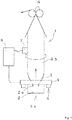
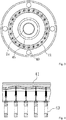
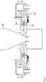
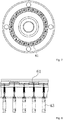
- FIGS. 1 to 4 illustrate a first embodiment of the present invention, in which FIG. 1 is a diagram illustrating a schematic configuration of an inflation film manufacturing apparatus, FIG. 2 is a schematic cross-sectional view of the inflation film manufacturing apparatus surrounding a thickness variation adjustment-type air ring, FIG. 3 is a cross-sectional view taken along arrows A-A in FIG. 2 , and FIG. 4 is a cross-sectional view taken along arrows B-B in FIG. 2 .
- a molten synthetic resin 3a supplied to a die 2 by an extruder (not illustrated) is extruded from a die slit 2a as a molten synthetic resin tube 3.
- the extruded molten synthetic resin tube 3 is thinly stretched in both left and right radial directions and is cooled by cooling air 5 from a blower (not illustrated), whereby a tubular synthetic resin film 3b is obtained.
- the synthetic resin film 3b is drawn by a pinch roll 6 and is wound around a winding machine (not illustrated). Air having a predetermined pressure is sealed inside the molten synthetic resin tube 3 (the tubular synthetic resin film 3b).
- the inflation film manufacturing apparatus 1 includes a thickness variation adjustment-type air ring 4 which is provided on the die 2 so as to locally control the volume of the cooling air 5 discharged from a cooling air passage 48 (see FIG. 2 ) into the circumferential direction to adjust the thickness variation of the synthetic resin film 3b when blowing the cooling air 5 around the molten synthetic resin tube 3 extruded in the longitudinal direction to cool and solidify the molten synthetic resin tube 3 to form the synthetic resin film 3b.
- a thickness variation adjustment-type air ring 4 which is provided on the die 2 so as to locally control the volume of the cooling air 5 discharged from a cooling air passage 48 (see FIG. 2 ) into the circumferential direction to adjust the thickness variation of the synthetic resin film 3b when blowing the cooling air 5 around the molten synthetic resin tube 3 extruded in the longitudinal direction to cool and solidify the molten synthetic resin tube 3 to form the synthetic resin film 3b.
- a thickness sensor 7 that measures the thickness of the tubular synthetic resin film 3b is provided on an upstream side of the pinch roll 6.
- the thickness sensor 7 is, for example, an electrostatic capacitance-type sensor, a laser-type sensor, or the like, in which a detection signal related to thickness variation information of the synthetic resin film 3b is input from the thickness sensor 7 into a control unit 8 which is formed as a computer or the like.
- the control unit 8 modulates a ring-shaped passage adjustment portion arranged sequentially inside the cooling air passage 48 of the air ring 4 in the circumferential direction with the aid of a moving portion, based on the thickness variation information of the synthetic resin film 3b, obtained from the detection signal of the thickness sensor 7, to thereby locally control the volume of the cooling air 5 flowing through the cooling air passage 48 in the circumferential direction so that the thickness variation of the synthetic resin film 3b is decreased and equalized.
- the air ring 4 is disposed horizontally and has a ring shape such that the inner side in the radial direction of the upper surface thereof is depressed. Moreover, the air ring 4 has a ring-shaped blow out opening 45 formed in an inner circumferential portion and is fixed to the die 2 by suitable means so as to be concentric with respect to the ring-shaped die slit 2a of the die 2.
- a cooling air trapping portion 44 is formed on the outer side in the radial direction inside the air ring 4 by a ring-shaped rectification plate 46.
- four hose openings 40 are formed in the cooling air trapping portion 44 separated at equal intervals in the circumferential direction, and the cooling air 5 from the blower (not illustrated) is introduced through hoses connected to these hose openings 40.
- the cooling air passage 48 connected to the cooling air trapping portion 44 is formed on the inner side in the radial direction inside the air ring 4, and a ring-shaped elastic member 41 formed sequentially in the circumferential direction is installed in the cooling air passage 48.
- the elastic member 41 forms a ring-shaped passage adjustment portion arranged sequentially in the circumferential direction inside of the cooling air passage 48.
- rod portions of a plurality of air cylinders 43 arranged in line in the circumferential direction are connected to the elastic member 41.
- each air cylinder 43 forms a moving portion that is connected to a predetermined position in the circumferential direction of the passage adjustment portion so as to move the connecting portion of the passage adjustment portion in a predetermined direction independently from the other portions.
- a coil spring 42 is attached to the rod portion of the air cylinder 43 so as to oppose the movement of the rod.
- the cooling air 5 from the blower (not illustrated) is distributed to four hoses and is introduced into the cooling air trapping portion 44 on the outer side of the air ring 4 from the hose opening 40.
- the cooling air 5 is rectified to a uniform flow toward the center in the radial direction while winding its way up and down through the rectification plates 46 and 47 and is discharged from the blow out opening 45 toward the molten synthetic resin tube 3.
- the cooling air passage 48 extends in the radial direction of the molten synthetic resin tube 3, and each air cylinder 43 moves the connecting portion of the elastic member 41 in the longitudinal direction of the molten synthetic resin tube 3 (that is, in the direction running vertical to the extension direction of the cooling air passage 48).
- a width of the cooling air passage 48 is between 3 mm and 50 mm, for example.
- the elastic member 41 having an endless structure does not have gaps formed in between joints, etc., the cooling air 5 rectified by the rectification plates 46 and 47 and the like is not disturbed by the elastic member 41. Moreover, it is possible to locally adjust the space in which the cooling air 5 can circulate inside the cooling air passage 48 with the aid of the elastic member 41 and to reliably control the volume of the cooling air 5 at all positions in the radial direction.
- the elastic member 41 Since it is difficult to deform the elastic member 41 if the elastic member 41 is too hard, rubber having hardness of 70° (JIS-A) is preferred. Moreover, the elastic member 41 may be adjusted using a stepping motor or the like instead of the air cylinder 43 and may be adjusted manually by a bolt or the like.
- the thickness variation adjustment-type air ring 4 having the above-described configuration, since it is not necessary to form a gap in the circumferential direction and it is possible to control the thickness variation locally and to control the cooling air at all positions in the circumferential direction, it is possible to form a uniform synthetic resin film 3b whose thickness variation is low.
- the air ring 4 of the inflation film manufacturing apparatus 1 of the first embodiment was manufactured and tested.
- a five-hour long continuous operation was performed under manufacturing conditions such that LLDPE having the MRF of 1 was used as the raw material for the molten synthetic resin 3a, a tube having a 1000 mm diameter and a tube whose thickness was 50 ⁇ m were used, and where the drawing speed was 23 m/minute, a synthetic resin film 3b whose thickness variation was between ⁇ 5.7% and ⁇ 6.4% (the thickness unevenness was based on average thickness) was obtained.
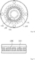
- FIGS. 5 and 6 illustrate a second embodiment of the present invention, in which FIG. 5 is a schematic cross-sectional view of an inflation film manufacturing apparatus and FIG. 6 is a cross-sectional view taken along arrows C-C in FIG. 5 .
- the moving direction of the passage adjustment portion may be set arbitrarily.
- the air cylinder 43 moves the connecting portion of the elastic member 51 in the radial direction of the molten synthetic resin tube 3 to locally adjust the gap of the cooling air passage 58 as well as to locally adjust the volume of cooling air, thereby controlling the thickness variation of the synthetic resin film 3b.
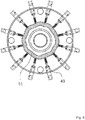
- FIGS. 7 and 8 illustrate a third embodiment which does not form part of the present invention, in which FIG. 7 is a planar cross-sectional view of a thickness variation adjustment-type air ring and FIG. 8 is a side cross-sectional view of the thickness variation adjustment-type air ring.
- the passage adjustment portion is formed as a plurality of movable members 61 which are arranged in a ring form without any gap in the circumferential direction and can move in the longitudinal direction of the molten synthetic resin tube 3. Since the movable members 61 can move the air cylinder 43 in a vertical direction in relation to a horizontal surface and no gap is formed between the movable members 61, the flow of the cooling air 5 is not disturbed, and it is possible to locally control the cooling air 5 as intended at all positions .
- the thickness variation adjustment-type air ring of the present invention can accurately and optimally control the volume of cooling air at all positions in the circumferential direction and stably manufacture a synthetic resin film having an exceptionally low thickness variation.
Landscapes
- Engineering & Computer Science (AREA)
- Mechanical Engineering (AREA)
- Physics & Mathematics (AREA)
- Thermal Sciences (AREA)
- Manufacturing & Machinery (AREA)
- Shaping By String And By Release Of Stress In Plastics And The Like (AREA)
- Extrusion Moulding Of Plastics Or The Like (AREA)
Claims (5)
- Dickenvariationseinstellender Luftring (4), der auf einer Düse (2) einer Vorrichtung (1) zur Herstellung eines aufblasbaren Films vorgesehen ist und der lokal das Volumen von Kühlluft (5), die von einer ringförmigen Ausblasöffnung (45) eines Kühlluftkanals (48; 58) ausströmt, in einer Umfangsrichtung steuert, um die Dickenvariation eines Kunstharzfilms (3b) einzustellen, wenn die Kühlluft (5) um einen geschmolzenen Kunstharzschlauch (3) geblasen wird, der in einer Längsrichtung extrudiert wird, um den geschmolzenen Kunstharzschlauch (3) zu kühlen und zu verfestigen, um den Kunstharzfilm (3b) zu bilden, wobei der dickenvariationseinstellende Luftring (4) umfasst:- einen ringförmigen Durchgangseinstellabschnitt (41, 51), der in Umfangsrichtung sequenziell innerhalb des Kühlluftkanals (48; 58) angeordnet ist, und- eine Mehrzahl von Bewegungsabschnitten (43), die an einer vorbestimmten Position in der Umfangsrichtung des Durchgangseinstellabschnitts (41, 51) verbunden sind, um einen Verbindungsabschnitt des Durchgangseinstellabschnitts in einer vorbestimmten Richtung unabhängig von anderen Abschnitten zu bewegen,wobei ein Raum, in dem die Kühlluft (5) innerhalb des Kühlluftkanals (48; 58) zirkuliert, lokal in der Umfangsrichtung eingestellt wird und das Volumen der Kühlluft (5) lokal in der Umfangsrichtung gesteuert wird, bevor sie aus der ringförmigen Ausblasöffnung (45) ausgeblasen wird,
wobei der Durchgangseinstellabschnitt aus einem ringförmigen elastischen Element (41; 51) gebildet ist, das in der Umfangsrichtung sequenziell zu der ringförmigen Ausblasöffnung (45) ausgebildet ist,
und wobei jede der Mehrzahl von Bewegungsabschnitten (43) einen Stangenabschnitt aufweist, der sich in der vorbestimmten Richtung bewegt,
dadurch gekennzeichnet, dass das elastische Element (41; 51) mit den Stangenabschnitten verbunden ist. - Dickenvariationseinstellender Luftring (4) nach Anspruch 1, wobei der Bewegungsabschnitt (43) einen Verbindungsabschnitt des elastischen Elements (41) in der Längsrichtung des geschmolzenen Kunstharzschlauchs (3) bewegt.
- Dickenvariationseinstellender Luftring (4) nach Anspruch 1, wobei der Bewegungsabschnitt (43) einen Verbindungsabschnitt des elastischen Elements (41; 51) in der radialen Richtung des geschmolzenen Kunstharzschlauchs (3) bewegt.
- Dickenvariationseinstellender Luftring (4) nach Anspruch 1 oder 2, wobei der Bewegungsabschnitt ein Luftzylinder (43) ist.
- Dickenvariationseinstellender Luftring (4) nach Anspruch 4, wobei der Luftzylinder (43) eine Schraubenfeder (42) aufweist, die eine Kraft auf den Stangenabschnitt ausübt.
Applications Claiming Priority (2)
| Application Number | Priority Date | Filing Date | Title |
|---|---|---|---|
| JP2014083122A JP5634630B1 (ja) | 2014-04-14 | 2014-04-14 | 偏肉調整型エアーリング |
| PCT/JP2015/057986 WO2015159634A1 (ja) | 2014-04-14 | 2015-03-18 | 偏肉調整型エアーリング |
Publications (3)
| Publication Number | Publication Date |
|---|---|
| EP3132913A1 EP3132913A1 (de) | 2017-02-22 |
| EP3132913A4 EP3132913A4 (de) | 2017-10-18 |
| EP3132913B1 true EP3132913B1 (de) | 2021-08-18 |
Family
ID=52139040
Family Applications (1)
| Application Number | Title | Priority Date | Filing Date |
|---|---|---|---|
| EP15779799.4A Revoked EP3132913B1 (de) | 2014-04-14 | 2015-03-18 | Einstellbarer kühlring zur dickensteuerung |
Country Status (8)
| Country | Link |
|---|---|
| US (1) | US10232543B2 (de) |
| EP (1) | EP3132913B1 (de) |
| JP (1) | JP5634630B1 (de) |
| KR (1) | KR102270002B1 (de) |
| CN (1) | CN106163766B (de) |
| CA (1) | CA2944135C (de) |
| TW (1) | TWI532585B (de) |
| WO (1) | WO2015159634A1 (de) |
Families Citing this family (19)
| Publication number | Priority date | Publication date | Assignee | Title |
|---|---|---|---|---|
| JP6366527B2 (ja) * | 2015-03-11 | 2018-08-01 | 住友重機械モダン株式会社 | フィルム成形装置のバルブ装置 |
| EP3088370B1 (de) * | 2015-04-28 | 2018-09-26 | Heraeus Quarzglas GmbH & Co. KG | Verfahren und vorrichtung zur herstellung eines rohres aus glas |
| ITUB20151292A1 (it) * | 2015-05-28 | 2016-11-28 | Doteco S P A | Apparato e metodo per produrre un film estruso in bolla |
| WO2017150307A1 (ja) * | 2016-02-29 | 2017-09-08 | 株式会社Tbm | インフレーションフィルムの製造方法及びインフレーション成形装置 |
| JP6704644B2 (ja) * | 2016-03-28 | 2020-06-03 | 住友重機械モダン株式会社 | フィルム成形装置 |
| WO2018036971A1 (de) * | 2016-08-23 | 2018-03-01 | Windmöller & Hölscher Kg | Vorrichtung und verfahren zur folienherstellung und/oder folienbearbeitung |
| JP6982518B2 (ja) * | 2017-03-30 | 2021-12-17 | 住友重機械モダン株式会社 | フィルム成形装置 |
| IT201700055831A1 (it) * | 2017-05-23 | 2018-11-23 | Syncro S R L | Dispositivo e metodo per regolare il profilo di spessore nella produzione di film soffiati |
| CN108638478B (zh) * | 2018-05-30 | 2023-11-07 | 联塑市政管道(河北)有限公司 | 一种可自动清理杂质的预冷水环 |
| CN109435204A (zh) * | 2018-10-23 | 2019-03-08 | 河北三能科技有限公司 | 一种用于控制橡胶挤出机的巡航定速控制系统及方法 |
| EP3753710B1 (de) * | 2019-06-21 | 2024-01-03 | PackSys Global AG | Optimierte kühleinrichtung, vorrichtung und verfahren zum herstellen von tubenkörpern |
| CN110315742A (zh) * | 2019-07-03 | 2019-10-11 | 广州市粤盛工贸有限公司 | 一种可调节局部风量的吹塑机风环组件 |
| CN111016115A (zh) * | 2019-12-31 | 2020-04-17 | 福建连众智惠实业有限公司 | 一种全自动风环 |
| US11618200B2 (en) * | 2020-03-17 | 2023-04-04 | Michael P. Bucko | External cooling air ring for blown-film extrusion |
| JP7411478B2 (ja) * | 2020-03-31 | 2024-01-11 | 住友重機械モダン株式会社 | インフレーション成形装置 |
| CN112629810B (zh) * | 2020-12-21 | 2025-04-25 | 中国计量大学 | 一种一体轴式曲面静压节流器气膜参数测量装置及方法 |
| CN112976530B (zh) * | 2021-02-22 | 2022-12-27 | 重庆市九龙橡胶制品制造有限公司 | 橡胶带挤压冷却装置 |
| US11826941B1 (en) | 2022-06-28 | 2023-11-28 | Daniel R. Joseph | Air ring for blown-film extrusion apparatus |
| EP4349564A1 (de) | 2022-10-04 | 2024-04-10 | Plast-Control GmbH | Kühlring zum kühlen eines folienschlauches |
Citations (14)
| Publication number | Priority date | Publication date | Assignee | Title |
|---|---|---|---|---|
| GB854368A (en) | 1956-02-20 | 1960-11-16 | Celanese Corp | Production of seamless tubing |
| JPS5464173U (de) | 1977-10-17 | 1979-05-07 | ||
| JPS56164824A (en) | 1980-04-18 | 1981-12-18 | Windmoeller & Hoelscher | Method of controlling thickness of tubular film formed by swelling film extruding device |
| JPS5915518U (ja) | 1982-07-21 | 1984-01-30 | 日本ユニカ−株式会社 | インフレ−シヨンフイルム用冷却装置 |
| DE4001287A1 (de) | 1990-01-18 | 1991-07-25 | Stefan Konermann | Verfahren zur herstellung von blasfolien in einer folienblasanlage |
| DE4218997C1 (de) | 1992-06-10 | 1994-01-20 | Reifenhaeuser Masch | Blasfolien-Extruderanlage für die Herstellung einer Kunststoffolie und Verfahren zum Betrieb der Blasfolien-Extruderanlage |
| JPH07205279A (ja) | 1994-01-24 | 1995-08-08 | Tomy Kikai Kogyo Kk | 押出成型装置の冷却風供給装置 |
| DE3745138C2 (de) | 1987-12-23 | 1997-08-21 | Veit Holger Karl Prof Dr Ing | Folienblasanlage zur Herstellung von Kunststoffolien |
| US5676893A (en) | 1993-12-01 | 1997-10-14 | Addex Design, Inc. | Cooling and thickness control for extruded products |
| EP1004424A1 (de) | 1998-09-04 | 2000-05-31 | Macro Engineering & Technology Inc. | Luftring zum Kühlen eines Folienschlauches aus thermoplastischem Kunststoff |
| US20020130431A1 (en) | 2001-03-15 | 2002-09-19 | William Randolph | External thickness control and method |
| JP2004276505A (ja) | 2003-03-18 | 2004-10-07 | Yokogawa Electric Corp | ブローンフィルム製造装置 |
| EP1736297A1 (de) | 2005-06-23 | 2006-12-27 | Kdesign GmbH | Steuerbarer Kühlgasring mit Gleichrichtereinheit sowie Verfahren zur Steuerung und/oder Regelung eines Kühlgasringes bei der Herstellung von Blasfolien aus thermoplastischem Kunststoff |
| JP2009269382A (ja) | 2008-05-01 | 2009-11-19 | Akira Shimizu | 偏肉調整型エアーリング |
Family Cites Families (11)
| Publication number | Priority date | Publication date | Assignee | Title |
|---|---|---|---|---|
| US4443400A (en) * | 1982-08-11 | 1984-04-17 | Mobil Oil Corporation | Method and apparatus for the formation of profiled thermoplastic film |
| CA2062827C (en) * | 1989-06-21 | 2000-09-12 | Stefan Konermann | Process and device for producing bubble-film |
| US5562926A (en) * | 1991-05-10 | 1996-10-08 | Karl; Veit-Holger | Film-blowing plant for manufacturing plastic films |
| JP2981633B2 (ja) | 1992-02-10 | 1999-11-22 | アルピネ・アクチエンゲゼルシャフト | チューブ状フイルム製造装置 |
| JP2954858B2 (ja) * | 1994-09-16 | 1999-09-27 | 日精エー・エス・ビー機械株式会社 | 射出延伸ブロー成形装置及び方法 |
| CN1218739A (zh) * | 1997-11-28 | 1999-06-09 | 马科工程及技术公司 | 用于冷却吹塑薄膜的气流环 |
| CN2677141Y (zh) * | 2004-03-01 | 2005-02-09 | 山东清源集团有限公司 | 风量可调式吹塑机风环 |
| CN201313376Y (zh) * | 2008-12-17 | 2009-09-23 | 佛山市顺德区捷勒塑料设备有限公司 | 管状薄层生产设备冷却装置的调节机构 |
| CN201442338U (zh) * | 2009-07-21 | 2010-04-28 | 大连橡胶塑料机械股份有限公司 | 吹膜机双风道可调冷却风环装置 |
| CN201471725U (zh) * | 2009-08-14 | 2010-05-19 | 詹文聪 | 吹袋机的冷却风环结构 |
| ITMI20131702A1 (it) * | 2013-10-15 | 2015-04-16 | Syncro S R L | Dispositivo e metodo per regolare il profilo di spessore nella produzione di film soffiati |
-
2014
- 2014-04-14 JP JP2014083122A patent/JP5634630B1/ja active Active
-
2015
- 2015-03-18 CN CN201580018984.9A patent/CN106163766B/zh not_active Expired - Fee Related
- 2015-03-18 US US15/301,244 patent/US10232543B2/en active Active
- 2015-03-18 CA CA2944135A patent/CA2944135C/en active Active
- 2015-03-18 EP EP15779799.4A patent/EP3132913B1/de not_active Revoked
- 2015-03-18 WO PCT/JP2015/057986 patent/WO2015159634A1/ja not_active Ceased
- 2015-03-18 KR KR1020167027900A patent/KR102270002B1/ko not_active Expired - Fee Related
- 2015-03-23 TW TW104109159A patent/TWI532585B/zh not_active IP Right Cessation
Patent Citations (15)
| Publication number | Priority date | Publication date | Assignee | Title |
|---|---|---|---|---|
| GB854368A (en) | 1956-02-20 | 1960-11-16 | Celanese Corp | Production of seamless tubing |
| JPS5464173U (de) | 1977-10-17 | 1979-05-07 | ||
| JPS56164824A (en) | 1980-04-18 | 1981-12-18 | Windmoeller & Hoelscher | Method of controlling thickness of tubular film formed by swelling film extruding device |
| JPS5915518U (ja) | 1982-07-21 | 1984-01-30 | 日本ユニカ−株式会社 | インフレ−シヨンフイルム用冷却装置 |
| DE3745138C2 (de) | 1987-12-23 | 1997-08-21 | Veit Holger Karl Prof Dr Ing | Folienblasanlage zur Herstellung von Kunststoffolien |
| DE4001287A1 (de) | 1990-01-18 | 1991-07-25 | Stefan Konermann | Verfahren zur herstellung von blasfolien in einer folienblasanlage |
| DE4218997C1 (de) | 1992-06-10 | 1994-01-20 | Reifenhaeuser Masch | Blasfolien-Extruderanlage für die Herstellung einer Kunststoffolie und Verfahren zum Betrieb der Blasfolien-Extruderanlage |
| US5676893A (en) | 1993-12-01 | 1997-10-14 | Addex Design, Inc. | Cooling and thickness control for extruded products |
| JPH07205279A (ja) | 1994-01-24 | 1995-08-08 | Tomy Kikai Kogyo Kk | 押出成型装置の冷却風供給装置 |
| EP1004424A1 (de) | 1998-09-04 | 2000-05-31 | Macro Engineering & Technology Inc. | Luftring zum Kühlen eines Folienschlauches aus thermoplastischem Kunststoff |
| US20020130431A1 (en) | 2001-03-15 | 2002-09-19 | William Randolph | External thickness control and method |
| EP1377796A2 (de) | 2001-03-15 | 2004-01-07 | Addex, Inc. | Externe dickenkontrolle und verfahren |
| JP2004276505A (ja) | 2003-03-18 | 2004-10-07 | Yokogawa Electric Corp | ブローンフィルム製造装置 |
| EP1736297A1 (de) | 2005-06-23 | 2006-12-27 | Kdesign GmbH | Steuerbarer Kühlgasring mit Gleichrichtereinheit sowie Verfahren zur Steuerung und/oder Regelung eines Kühlgasringes bei der Herstellung von Blasfolien aus thermoplastischem Kunststoff |
| JP2009269382A (ja) | 2008-05-01 | 2009-11-19 | Akira Shimizu | 偏肉調整型エアーリング |
Also Published As
| Publication number | Publication date |
|---|---|
| EP3132913A4 (de) | 2017-10-18 |
| JP5634630B1 (ja) | 2014-12-03 |
| US10232543B2 (en) | 2019-03-19 |
| TW201540478A (zh) | 2015-11-01 |
| CA2944135A1 (en) | 2015-10-22 |
| KR102270002B1 (ko) | 2021-06-25 |
| CN106163766A (zh) | 2016-11-23 |
| WO2015159634A1 (ja) | 2015-10-22 |
| CN106163766B (zh) | 2019-12-24 |
| JP2017104983A (ja) | 2017-06-15 |
| EP3132913A1 (de) | 2017-02-22 |
| TWI532585B (zh) | 2016-05-11 |
| US20170015043A1 (en) | 2017-01-19 |
| CA2944135C (en) | 2020-12-29 |
| KR20160144998A (ko) | 2016-12-19 |
Similar Documents
| Publication | Publication Date | Title |
|---|---|---|
| EP3132913B1 (de) | Einstellbarer kühlring zur dickensteuerung | |
| FI114144B (fi) | Menetelmä biaksaalisesti suunnatun putken valmistamiseksi | |
| US9457526B2 (en) | Calibration device for calibrating an extruded film tube | |
| NZ277684A (en) | Automatic system for controlling cooling and details of means for varying amount and position of cooling air directed at film | |
| US6739855B2 (en) | External thickness control and method | |
| US12162201B2 (en) | External cooling air ring for blown-film extrusion | |
| ITMI20001937A1 (it) | Procedimento e dispositivo per comandare e regolare il profilo di spessore nella produzione di film soffiati | |
| US20150283752A1 (en) | Apparatus and Method for Cooling Plastic Film Tube in Blown Film Process | |
| CN1065037A (zh) | 制造长带材的设备和方法 | |
| US20230158727A1 (en) | Method and apparatus for cooling | |
| US20020018822A1 (en) | Air cooling ring for blown plastics film | |
| JP2009269382A (ja) | 偏肉調整型エアーリング | |
| CN111163917A (zh) | 用于挤出的塑料制品的生产控制的方法和设备以及用于挤出这种塑料制品的挤出系统 | |
| US20080095874A1 (en) | Device for extruding hollow strands | |
| CN105658404A (zh) | 吹塑薄膜设备和用于运行吹塑薄膜设备的方法 | |
| CA2438493A1 (en) | Film die for the production of tubular film | |
| GB2293131A (en) | Apparatus for producing blown films from synthetic thermoplastic material | |
| CA2556874A1 (en) | Calibration basket for a calibration station | |
| CA2340812A1 (en) | Outside bubble air cooling ring for blown plastic film | |
| FI70540B (fi) | Foerfarande och anordning foer tillverkning av en bana av skummat termoplastiskt material | |
| EP3768490B1 (de) | Verfahren und vorrichtung zur kühlung |
Legal Events
| Date | Code | Title | Description |
|---|---|---|---|
| STAA | Information on the status of an ep patent application or granted ep patent |
Free format text: STATUS: THE INTERNATIONAL PUBLICATION HAS BEEN MADE |
|
| PUAI | Public reference made under article 153(3) epc to a published international application that has entered the european phase |
Free format text: ORIGINAL CODE: 0009012 |
|
| STAA | Information on the status of an ep patent application or granted ep patent |
Free format text: STATUS: REQUEST FOR EXAMINATION WAS MADE |
|
| 17P | Request for examination filed |
Effective date: 20161114 |
|
| AK | Designated contracting states |
Kind code of ref document: A1 Designated state(s): AL AT BE BG CH CY CZ DE DK EE ES FI FR GB GR HR HU IE IS IT LI LT LU LV MC MK MT NL NO PL PT RO RS SE SI SK SM TR |
|
| AX | Request for extension of the european patent |
Extension state: BA ME |
|
| TPAC | Observations filed by third parties |
Free format text: ORIGINAL CODE: EPIDOSNTIPA |
|
| DAV | Request for validation of the european patent (deleted) | ||
| DAX | Request for extension of the european patent (deleted) | ||
| A4 | Supplementary search report drawn up and despatched |
Effective date: 20170919 |
|
| RIC1 | Information provided on ipc code assigned before grant |
Ipc: B29C 47/92 20060101ALI20170913BHEP Ipc: B29C 55/28 20060101ALN20170913BHEP Ipc: B29C 47/88 20060101AFI20170913BHEP |
|
| STAA | Information on the status of an ep patent application or granted ep patent |
Free format text: STATUS: EXAMINATION IS IN PROGRESS |
|
| 17Q | First examination report despatched |
Effective date: 20191106 |
|
| REG | Reference to a national code |
Ref country code: DE Ref legal event code: R079 Ref document number: 602015072405 Country of ref document: DE Free format text: PREVIOUS MAIN CLASS: B29C0055280000 Ipc: B29C0048100000 |
|
| GRAP | Despatch of communication of intention to grant a patent |
Free format text: ORIGINAL CODE: EPIDOSNIGR1 |
|
| STAA | Information on the status of an ep patent application or granted ep patent |
Free format text: STATUS: GRANT OF PATENT IS INTENDED |
|
| RIC1 | Information provided on ipc code assigned before grant |
Ipc: B29C 48/10 20190101AFI20210222BHEP Ipc: B29C 48/92 20190101ALI20210222BHEP Ipc: B29C 48/88 20190101ALI20210222BHEP Ipc: B29C 55/28 20060101ALN20210222BHEP |
|
| INTG | Intention to grant announced |
Effective date: 20210316 |
|
| GRAS | Grant fee paid |
Free format text: ORIGINAL CODE: EPIDOSNIGR3 |
|
| GRAA | (expected) grant |
Free format text: ORIGINAL CODE: 0009210 |
|
| STAA | Information on the status of an ep patent application or granted ep patent |
Free format text: STATUS: THE PATENT HAS BEEN GRANTED |
|
| AK | Designated contracting states |
Kind code of ref document: B1 Designated state(s): AL AT BE BG CH CY CZ DE DK EE ES FI FR GB GR HR HU IE IS IT LI LT LU LV MC MK MT NL NO PL PT RO RS SE SI SK SM TR |
|
| REG | Reference to a national code |
Ref country code: GB Ref legal event code: FG4D |
|
| REG | Reference to a national code |
Ref country code: CH Ref legal event code: EP |
|
| REG | Reference to a national code |
Ref country code: DE Ref legal event code: R096 Ref document number: 602015072405 Country of ref document: DE |
|
| REG | Reference to a national code |
Ref country code: IE Ref legal event code: FG4D Ref country code: AT Ref legal event code: REF Ref document number: 1421239 Country of ref document: AT Kind code of ref document: T Effective date: 20210915 |
|
| REG | Reference to a national code |
Ref country code: LT Ref legal event code: MG9D |
|
| REG | Reference to a national code |
Ref country code: AT Ref legal event code: MK05 Ref document number: 1421239 Country of ref document: AT Kind code of ref document: T Effective date: 20210818 |
|
| PG25 | Lapsed in a contracting state [announced via postgrant information from national office to epo] |
Ref country code: RS Free format text: LAPSE BECAUSE OF FAILURE TO SUBMIT A TRANSLATION OF THE DESCRIPTION OR TO PAY THE FEE WITHIN THE PRESCRIBED TIME-LIMIT Effective date: 20210818 Ref country code: SE Free format text: LAPSE BECAUSE OF FAILURE TO SUBMIT A TRANSLATION OF THE DESCRIPTION OR TO PAY THE FEE WITHIN THE PRESCRIBED TIME-LIMIT Effective date: 20210818 Ref country code: HR Free format text: LAPSE BECAUSE OF FAILURE TO SUBMIT A TRANSLATION OF THE DESCRIPTION OR TO PAY THE FEE WITHIN THE PRESCRIBED TIME-LIMIT Effective date: 20210818 Ref country code: ES Free format text: LAPSE BECAUSE OF FAILURE TO SUBMIT A TRANSLATION OF THE DESCRIPTION OR TO PAY THE FEE WITHIN THE PRESCRIBED TIME-LIMIT Effective date: 20210818 Ref country code: FI Free format text: LAPSE BECAUSE OF FAILURE TO SUBMIT A TRANSLATION OF THE DESCRIPTION OR TO PAY THE FEE WITHIN THE PRESCRIBED TIME-LIMIT Effective date: 20210818 Ref country code: PT Free format text: LAPSE BECAUSE OF FAILURE TO SUBMIT A TRANSLATION OF THE DESCRIPTION OR TO PAY THE FEE WITHIN THE PRESCRIBED TIME-LIMIT Effective date: 20211220 Ref country code: NO Free format text: LAPSE BECAUSE OF FAILURE TO SUBMIT A TRANSLATION OF THE DESCRIPTION OR TO PAY THE FEE WITHIN THE PRESCRIBED TIME-LIMIT Effective date: 20211118 Ref country code: BG Free format text: LAPSE BECAUSE OF FAILURE TO SUBMIT A TRANSLATION OF THE DESCRIPTION OR TO PAY THE FEE WITHIN THE PRESCRIBED TIME-LIMIT Effective date: 20211118 Ref country code: AT Free format text: LAPSE BECAUSE OF FAILURE TO SUBMIT A TRANSLATION OF THE DESCRIPTION OR TO PAY THE FEE WITHIN THE PRESCRIBED TIME-LIMIT Effective date: 20210818 Ref country code: LT Free format text: LAPSE BECAUSE OF FAILURE TO SUBMIT A TRANSLATION OF THE DESCRIPTION OR TO PAY THE FEE WITHIN THE PRESCRIBED TIME-LIMIT Effective date: 20210818 |
|
| PG25 | Lapsed in a contracting state [announced via postgrant information from national office to epo] |
Ref country code: PL Free format text: LAPSE BECAUSE OF FAILURE TO SUBMIT A TRANSLATION OF THE DESCRIPTION OR TO PAY THE FEE WITHIN THE PRESCRIBED TIME-LIMIT Effective date: 20210818 Ref country code: LV Free format text: LAPSE BECAUSE OF FAILURE TO SUBMIT A TRANSLATION OF THE DESCRIPTION OR TO PAY THE FEE WITHIN THE PRESCRIBED TIME-LIMIT Effective date: 20210818 Ref country code: GR Free format text: LAPSE BECAUSE OF FAILURE TO SUBMIT A TRANSLATION OF THE DESCRIPTION OR TO PAY THE FEE WITHIN THE PRESCRIBED TIME-LIMIT Effective date: 20211119 |
|
| PG25 | Lapsed in a contracting state [announced via postgrant information from national office to epo] |
Ref country code: NL Free format text: LAPSE BECAUSE OF FAILURE TO SUBMIT A TRANSLATION OF THE DESCRIPTION OR TO PAY THE FEE WITHIN THE PRESCRIBED TIME-LIMIT Effective date: 20210818 |
|
| PG25 | Lapsed in a contracting state [announced via postgrant information from national office to epo] |
Ref country code: DK Free format text: LAPSE BECAUSE OF FAILURE TO SUBMIT A TRANSLATION OF THE DESCRIPTION OR TO PAY THE FEE WITHIN THE PRESCRIBED TIME-LIMIT Effective date: 20210818 |
|
| REG | Reference to a national code |
Ref country code: DE Ref legal event code: R026 Ref document number: 602015072405 Country of ref document: DE |
|
| PLBI | Opposition filed |
Free format text: ORIGINAL CODE: 0009260 |
|
| PLAB | Opposition data, opponent's data or that of the opponent's representative modified |
Free format text: ORIGINAL CODE: 0009299OPPO |
|
| PG25 | Lapsed in a contracting state [announced via postgrant information from national office to epo] |
Ref country code: SM Free format text: LAPSE BECAUSE OF FAILURE TO SUBMIT A TRANSLATION OF THE DESCRIPTION OR TO PAY THE FEE WITHIN THE PRESCRIBED TIME-LIMIT Effective date: 20210818 Ref country code: SK Free format text: LAPSE BECAUSE OF FAILURE TO SUBMIT A TRANSLATION OF THE DESCRIPTION OR TO PAY THE FEE WITHIN THE PRESCRIBED TIME-LIMIT Effective date: 20210818 Ref country code: RO Free format text: LAPSE BECAUSE OF FAILURE TO SUBMIT A TRANSLATION OF THE DESCRIPTION OR TO PAY THE FEE WITHIN THE PRESCRIBED TIME-LIMIT Effective date: 20210818 Ref country code: EE Free format text: LAPSE BECAUSE OF FAILURE TO SUBMIT A TRANSLATION OF THE DESCRIPTION OR TO PAY THE FEE WITHIN THE PRESCRIBED TIME-LIMIT Effective date: 20210818 Ref country code: CZ Free format text: LAPSE BECAUSE OF FAILURE TO SUBMIT A TRANSLATION OF THE DESCRIPTION OR TO PAY THE FEE WITHIN THE PRESCRIBED TIME-LIMIT Effective date: 20210818 Ref country code: AL Free format text: LAPSE BECAUSE OF FAILURE TO SUBMIT A TRANSLATION OF THE DESCRIPTION OR TO PAY THE FEE WITHIN THE PRESCRIBED TIME-LIMIT Effective date: 20210818 |
|
| 26 | Opposition filed |
Opponent name: PLAST-CONTROL GMBH Effective date: 20220511 Opponent name: KDESIGN GMBH Effective date: 20220506 |
|
| R26 | Opposition filed (corrected) |
Opponent name: PLAST-CONTROL GMBH Effective date: 20220511 Opponent name: KDESIGN GMBH Effective date: 20220506 |
|
| PLAX | Notice of opposition and request to file observation + time limit sent |
Free format text: ORIGINAL CODE: EPIDOSNOBS2 |
|
| PG25 | Lapsed in a contracting state [announced via postgrant information from national office to epo] |
Ref country code: SI Free format text: LAPSE BECAUSE OF FAILURE TO SUBMIT A TRANSLATION OF THE DESCRIPTION OR TO PAY THE FEE WITHIN THE PRESCRIBED TIME-LIMIT Effective date: 20210818 |
|
| PG25 | Lapsed in a contracting state [announced via postgrant information from national office to epo] |
Ref country code: MC Free format text: LAPSE BECAUSE OF FAILURE TO SUBMIT A TRANSLATION OF THE DESCRIPTION OR TO PAY THE FEE WITHIN THE PRESCRIBED TIME-LIMIT Effective date: 20210818 |
|
| REG | Reference to a national code |
Ref country code: CH Ref legal event code: PL |
|
| GBPC | Gb: european patent ceased through non-payment of renewal fee |
Effective date: 20220318 |
|
| PLBB | Reply of patent proprietor to notice(s) of opposition received |
Free format text: ORIGINAL CODE: EPIDOSNOBS3 |
|
| REG | Reference to a national code |
Ref country code: BE Ref legal event code: MM Effective date: 20220331 |
|
| PG25 | Lapsed in a contracting state [announced via postgrant information from national office to epo] |
Ref country code: LU Free format text: LAPSE BECAUSE OF NON-PAYMENT OF DUE FEES Effective date: 20220318 Ref country code: LI Free format text: LAPSE BECAUSE OF NON-PAYMENT OF DUE FEES Effective date: 20220331 Ref country code: IE Free format text: LAPSE BECAUSE OF NON-PAYMENT OF DUE FEES Effective date: 20220318 Ref country code: GB Free format text: LAPSE BECAUSE OF NON-PAYMENT OF DUE FEES Effective date: 20220318 Ref country code: FR Free format text: LAPSE BECAUSE OF NON-PAYMENT OF DUE FEES Effective date: 20220331 Ref country code: CH Free format text: LAPSE BECAUSE OF NON-PAYMENT OF DUE FEES Effective date: 20220331 |
|
| PG25 | Lapsed in a contracting state [announced via postgrant information from national office to epo] |
Ref country code: BE Free format text: LAPSE BECAUSE OF NON-PAYMENT OF DUE FEES Effective date: 20220331 |
|
| PG25 | Lapsed in a contracting state [announced via postgrant information from national office to epo] |
Ref country code: HU Free format text: LAPSE BECAUSE OF FAILURE TO SUBMIT A TRANSLATION OF THE DESCRIPTION OR TO PAY THE FEE WITHIN THE PRESCRIBED TIME-LIMIT; INVALID AB INITIO Effective date: 20150318 |
|
| PG25 | Lapsed in a contracting state [announced via postgrant information from national office to epo] |
Ref country code: MK Free format text: LAPSE BECAUSE OF FAILURE TO SUBMIT A TRANSLATION OF THE DESCRIPTION OR TO PAY THE FEE WITHIN THE PRESCRIBED TIME-LIMIT Effective date: 20210818 Ref country code: CY Free format text: LAPSE BECAUSE OF FAILURE TO SUBMIT A TRANSLATION OF THE DESCRIPTION OR TO PAY THE FEE WITHIN THE PRESCRIBED TIME-LIMIT Effective date: 20210818 |
|
| PGFP | Annual fee paid to national office [announced via postgrant information from national office to epo] |
Ref country code: DE Payment date: 20240325 Year of fee payment: 10 |
|
| PGFP | Annual fee paid to national office [announced via postgrant information from national office to epo] |
Ref country code: IT Payment date: 20240329 Year of fee payment: 10 |
|
| PG25 | Lapsed in a contracting state [announced via postgrant information from national office to epo] |
Ref country code: TR Free format text: LAPSE BECAUSE OF FAILURE TO SUBMIT A TRANSLATION OF THE DESCRIPTION OR TO PAY THE FEE WITHIN THE PRESCRIBED TIME-LIMIT Effective date: 20210818 |
|
| REG | Reference to a national code |
Ref country code: DE Ref legal event code: R103 Ref document number: 602015072405 Country of ref document: DE Ref country code: DE Ref legal event code: R064 Ref document number: 602015072405 Country of ref document: DE |
|
| PG25 | Lapsed in a contracting state [announced via postgrant information from national office to epo] |
Ref country code: MT Free format text: LAPSE BECAUSE OF FAILURE TO SUBMIT A TRANSLATION OF THE DESCRIPTION OR TO PAY THE FEE WITHIN THE PRESCRIBED TIME-LIMIT Effective date: 20210818 |
|
| RDAF | Communication despatched that patent is revoked |
Free format text: ORIGINAL CODE: EPIDOSNREV1 |
|
| RDAG | Patent revoked |
Free format text: ORIGINAL CODE: 0009271 |
|
| STAA | Information on the status of an ep patent application or granted ep patent |
Free format text: STATUS: PATENT REVOKED |
|
| REG | Reference to a national code |
Ref country code: CH Ref legal event code: PL |
|
| 27W | Patent revoked |
Effective date: 20240912 |