EP3129269B1 - Steuereinrichtung - Google Patents
Steuereinrichtung Download PDFInfo
- Publication number
- EP3129269B1 EP3129269B1 EP15718176.9A EP15718176A EP3129269B1 EP 3129269 B1 EP3129269 B1 EP 3129269B1 EP 15718176 A EP15718176 A EP 15718176A EP 3129269 B1 EP3129269 B1 EP 3129269B1
- Authority
- EP
- European Patent Office
- Prior art keywords
- rail vehicle
- operating unit
- control device
- contact point
- electrical contact
- Prior art date
- Legal status (The legal status is an assumption and is not a legal conclusion. Google has not performed a legal analysis and makes no representation as to the accuracy of the status listed.)
- Active
Links
Images

Classifications
-
- B—PERFORMING OPERATIONS; TRANSPORTING
- B61—RAILWAYS
- B61C—LOCOMOTIVES; MOTOR RAILCARS
- B61C17/00—Arrangement or disposition of parts; Details or accessories not otherwise provided for; Use of control gear and control systems
- B61C17/04—Arrangement or disposition of driving cabins, footplates or engine rooms; Ventilation thereof
-
- B—PERFORMING OPERATIONS; TRANSPORTING
- B60—VEHICLES IN GENERAL
- B60K—ARRANGEMENT OR MOUNTING OF PROPULSION UNITS OR OF TRANSMISSIONS IN VEHICLES; ARRANGEMENT OR MOUNTING OF PLURAL DIVERSE PRIME-MOVERS IN VEHICLES; AUXILIARY DRIVES FOR VEHICLES; INSTRUMENTATION OR DASHBOARDS FOR VEHICLES; ARRANGEMENTS IN CONNECTION WITH COOLING, AIR INTAKE, GAS EXHAUST OR FUEL SUPPLY OF PROPULSION UNITS IN VEHICLES
- B60K37/00—Dashboards
-
- B—PERFORMING OPERATIONS; TRANSPORTING
- B61—RAILWAYS
- B61L—GUIDING RAILWAY TRAFFIC; ENSURING THE SAFETY OF RAILWAY TRAFFIC
- B61L27/00—Central railway traffic control systems; Trackside control; Communication systems specially adapted therefor
Definitions
- the invention relates to a control device for a rail vehicle and a rail vehicle.
- Rail vehicles in particular locomotives, railcars, control cars and trams are generally equipped with control devices by means of which the driving operation is controllable.
- control devices include input devices such as travel and brake levers and electrical switches and output devices such as signal lamps or audible warning devices (buzzer).
- Newer vehicles have screens that can display a wide variety of information. Primary information (driving speed, door position, essential error messages) is distinguished from secondary information (error messages without urgency) and displayed differently.
- Such a control device (driver's desk) is arranged at Zweiiquessterrorismen (eg locomotives) on each front side of the vehicle in Girsterrorismen (eg trams) only at the leading end side.
- a driver's desk In vehicles for fully automatic driving, typically subways, however, a driver's desk is usually still provided, which, however, only in case of failure of the automatic control and is used in shunting.
- This driver's desk, or this control device can be performed as a conventional driver's cab, which requires a particularly large space requirement, or it can be provided a (simplified) driver's desk, which is hidden when not in use by cover flaps.
- Both embodiments have in common that they are extremely complicated to build and are expensive, since a large number of electrical components and lines are to be guided to the position of the control devices.
- the invention is therefore based on the object to provide a control device for a rail vehicle, which can be used in particular for the manual operation of automatic vehicles and which is characterized by particularly low component and installation costs.
- control device having the features of claim 1 and a rail vehicle according to claim 5.
- Advantageous embodiments are the subject of the subordinate claims.
- a control device for a driverless, fully automatic rail vehicle which comprises an operating unit with all required for the operation of the rail vehicle input and output devices, the control unit with a rail vehicle via a locatable in the interior of the rail vehicle multi-pole detachable electrical contact point is connectable, by means of which the control unit in a use position establishes a connection to the electrical systems of the rail vehicle.
- a portable control unit includes all the necessary for the operation of the rail vehicle displays and controls and manufactures all the required signal connections to the vehicle electronics by means of the detachable contact point.
- a correspondingly shaped mechanical interface for the operating unit is provided at the mounting position of the operating unit in the rail vehicle, which specifies the joining direction and the end position of the operating unit in the use position, so that rapid and unmistakable mounting can take place.
- this mechanical interface is also provided with a block, which allows removal of the operating unit only after release. This release can be done for example by means of a key switch or a release button.
- the detachable electrical contact point which generally comprises a large number of individual contacts, when not in use by means of a cover.
- the operating unit can advantageously be shaped in the manner of a portable computer (notebook), which folds is executed, thereby allowing easy transport.
- the controls and a possibly existing screen are protected by the hinged construction when not in use from damage.
- the controls are to be carried out according to the usual in rail vehicles input devices, typically a drive / brake lever, door control button, emergency stop button, horn operation, etc. are each provided as a specifically shaped input device.
- the operating unit is connected in use position via the detachable electrical interface with electrical equipment of the rail vehicle.
- These electrical devices may include, for example, the vehicle-mounted drive control, the carriage control, or other electrical devices be. It is advisable to use data bus systems for the electrical connection of the operating unit, since in this way the number of electrical contact points can be substantially reduced. For safety-critical signals (eg emergency brake operation, dead man's control, drive control or door operation), it is recommended to use dedicated signals and contact points, as this may cause actuation even if the bus system malfunctions.
- Fig.1 shows by way of example and schematically a block diagram of a rail vehicle with a control device. It is shown a rail vehicle 1, which comprises electrical devices 6, 7, 8, wherein the electrical Device 6 is a drive control, the electrical device 7 is a carriage controller and the electrical device 8 is a communication device. An electrical contact point 3 is provided, to which signals of the electrical devices 6, 7, 8 are routed. In this case, the signals of the drive control 6 are led directly to the electrical contact point 3, two signals being shown by way of example. The signals of the carriage controller 7 and the communication device 8 are guided via a common bus system 9 to the electrical contact point 3.
- This bus system 9 may be implemented according to the conventional embodiments of a bus system, for example as a data network (Ethernet), as an industrial bus (I2C), as an optical bus with a fiber optic cabling or the like.
- a control unit 2 is detachably connected, to which the signals of the electrical devices 6, 7, 8 are passed for mutual exchange of data.
- the operating unit 2 is designed as a portable device and comprises a screen 4 designed as display device and input devices. 5
- Fig.2 shows by way of example and schematically a rail vehicle with a receptacle for a control device.
- the interior is shown on a front region of a rail vehicle 1, which has a receptacle 11 for an operating unit 2.
- An electrical contact point 3 is protected by a cover 10 from contact and contamination.
- This in Fig.2 embodiment shown corresponds to a typical local transport vehicle, such as a subway, which is operated without a driver in normal operation.
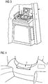
- Figure 3 shows by way of example and schematically a rail vehicle with a control device. It is the rail vehicle 1 out Fig.2 represented, with a control unit 2 is mounted.
- the operating unit 2 comprises, in addition to a screen 4, a plurality of input devices 5, in particular a drive lever which is designed similar to the drive levers which are permanently installed in vehicles.
- Figure 4 shows by way of example and schematically a rail vehicle for fully automatic operation. It is shown the front side of the passenger compartment of a rail vehicle 1, wherein the front side is provided for design reasons with round shapes. Due to these round shapes, it is not possible to fasten an operating unit 2 to the surface of the linings for emergency operation without further measures, so that a cover 10 is provided. The cover 10 closes a flat receiving surface for a control unit. 2
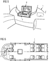
- Figure 5 shows by way of example and schematically a rail vehicle for fully automatic operation with an operating unit. It is the rail vehicle 1 off Figure 4 shown, with the cover 10 is removed. An operating unit 2 with a screen 4 is connected to the thus exposed electrical contact point 3. The electrical contact point 3 is in Figure 5 not shown, since it is hidden by the control unit 2.
- Figure 6 shows by way of example and schematically a rail vehicle with a wired control unit. It is the outline of a rail vehicle 1 shown, which is intended for fully automatic operation and thus has no driver's cab. For manual operation, the driver takes the middle seat of the first row and connects a control unit 2 by means of a Connecting cable with an electrical contact point 3. As a result, a cover 10 can be made much smaller, since it only has to cover the electrical contact point 3. Furthermore, this embodiment has the advantage that the driver can control the vehicle from a seat.
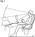
- Figure 7 shows by way of example and schematically a rail vehicle with a wired control unit in a detailed view. It is the rail vehicle 1 off Figure 6 shown in a detail page view of the driver.
- the operating unit 2 is connected by means of a bracket 13 fixed to the seat of the driver, so that a stable position is ensured.
- Figure 7 also represents the field of vision of the driver, the shape of the control unit 2 is tuned so that the required field of view is guaranteed.
- the holder 13 allows a releasable attachment of the control unit 2 to the rail vehicle 1, preferably a seat. This attachment is tool-less manufacturable and separable.
Landscapes
- Engineering & Computer Science (AREA)
- Mechanical Engineering (AREA)
- Transportation (AREA)
- Automation & Control Theory (AREA)
- Chemical & Material Sciences (AREA)
- Combustion & Propulsion (AREA)
- Electric Propulsion And Braking For Vehicles (AREA)
- Train Traffic Observation, Control, And Security (AREA)
Description
- Die Erfindung betrifft eine Steuereinrichtung für ein Schienenfahrzeug und ein Schienenfahrzeug.
- Schienenfahrzeuge, insbesondere Lokomotiven, Triebwagen, Steuerwagen und Straßenbahnen sind im Allgemeinen mit Steuereinrichtungen ausgestattet mittels welcher der Fahrbetrieb steuerbar ist. Diese Steuereinrichtungen umfassen Eingabeeinrichtungen wie Fahr- und Bremshebel sowie elektrische Schalter und Ausgabeeinrichtungen wie Signallampen oder akustische Warneinrichtungen (Summer). Neuere Fahrzeuge weisen Bildschirme auf, welche eine große Vielzahl an Informationen darstellen können. Dabei werden primäre Informationen (Fahrgeschwindigkeit, Türposition, wesentliche Fehlermeldungen) von sekundären Informationen (Fehlermeldungen ohne Dringlichkeit) unterschieden und jeweils unterschiedlich dargestellt. Eine solche Steuereinrichtung (Fahrerpult) ist bei Zweirichtungsfahrzeugen (z.B. Lokomotiven) an jeder Stirnseite des Fahrzeugs angeordnet, bei Einrichtungsfahrzeugen (z.B. Straßenbahnen) nur an der führenden Stirnseite. Bei Fahrzeugen für einen vollautomatischen Fahrbetrieb, typischerweise U-Bahnen ist jedoch meist trotzdem ein Fahrerpult vorgesehen, welches jedoch nur bei einer Störung der automatischen Steuerung und bei Rangierfahrten verwendet wird. Dieses Fahrerpult, bzw. diese Steuereinrichtung kann dabei als konventioneller Fahrerraum ausgeführt werden, was einen besonders großen Bauraumbedarf erfordert, oder es kann ein (vereinfachtes) Fahrerpult vorgesehen werden, welches bei Nichtgebrauch durch Abdeckklappen verborgen ist. Beiden Ausführungsformen ist gemein, dass sie äußerst kompliziert aufzubauen und teuer sind, da eine große Vielzahl an elektrischen Bauelementen und Leitungen an die Position der Steuereinrichtungen zu führen sind. Dies ist insbesondere bei gekuppelten Zugverbänden nachteilig, da beispielsweise bei zwei gekoppelten Zweirichtungsfahrzeugen vier Fahrerpulte vorgesehen sind, wobei die an den gekoppelten Zugenden nur nach einer Zugtrennung (beispielsweise im Wartungsfall) verwendet werden. Diese, im praktischen Betrieb äußerst selten eingesetzten Steuereinrichtungen verursachen trotzdem Wartungskosten Zum technischen Umfeld wird beispielsweise auf die
DE 19743306 A1 und dieDE 102009034681 A1 verwiesen. - Der Erfindung liegt daher die Aufgabe zugrunde, eine Steuereinrichtung für ein Schienenfahrzeug anzugeben, welche insbesondere für den manuellen Betrieb automatischer Fahrzeuge einsetzbar ist und welche sich durch besonders geringen Bauteil- und Installationsaufwand auszeichnet.
- Die Aufgabe wird durch eine Steuereinrichtung mit den Merkmalen des Anspruchs 1 und ein Schienenfahrzeug nach Anspruch 5 gelöst. Vorteilhafte Ausgestaltungen sind Gegenstand untergeordneter Ansprüche.
- Dem Grundgedanken der Erfindung nach wird eine Steuereinrichtung für ein fahrerstandsloses, vollautomatisch verkehrendes Schienenfahrzeug aufgebaut, welche eine Bedieneinheit mit allen zum Betrieb des Schienenfahrzeugs erforderlichen Ein- und Ausgabevorrichtungen umfasst, wobei die Bedieneinheit mit einem Schienenfahrzeug über eine im Innenraum des Schienenfahrzeugs anordenbare mehrpolige lösbare elektrische Kontaktstelle verbindbar ist, mittels welcher die Bedieneinheit in einer Gebrauchsposition eine Verbindung zu den elektrischen Systemen des Schienenfahrzeugs herstellt.
- Dadurch ist der Vorteil erzielbar, ein Fahrerpult schnell einrichten bzw. aufbauen zu können, wobei eine transportable Bedieneinheit alle für den Betrieb des Schienenfahrzeugs erforderlichen Anzeigen und Bedienelemente umfasst und mittels der lösbaren Kontaktstelle alle erforderlichen Signalverbindungen zu der Fahrzeugelektronik herstellt.
- Dies ist insbesondere für vollautomatisch verkehrende Schienenfahrzeuge vorteilhaft, da für diese Fahrzeuge bei Einsatz gegenständlicher Erfindung auch keinerlei Notfahrpulte vorzusehen sind. Erfindungsgemäß ist an der Montageposition der Bedieneinheit in dem Schienenfahrzeug eine entsprechend geformte mechanische Schnittstelle für die Bedieneinheit vorzusehen, welche die Fügerichtung und die Endlage der Bedieneinheit in Gebrauchsposition vorgibt, sodass eine rasche und unmissverständliche Montage erfolgen kann. Erfindungsgemäß ist auch diese mechanische Schnittstelle mit einer Blockierung versehen, welche eine Entnahme der Bedieneinheit erst nach einer Freigabe ermöglicht. Diese Freigabe kann beispielsweise mittels eines Schlüsselschalters oder einer Auslösetaste erfolgen.
- In weiterer Fortbildung der Erfindung ist es empfehlenswert, die lösbare elektrische Kontaktstelle, welche im Allgemeinen eine hohe Anzahl einzelner Kontakte umfasst, bei Nichtgebrauch mittels einer Abdeckung zu verschließen.
- Dadurch kann einerseits eine Beschädigung bzw. Verschmutzung der Kontakte verhindert werden, andererseits ist solcherart eine leichtere Reinigung des Innenraums möglich. Vorbeugend, um Vandalismus zu verhindern ist es zweckmäßig, diese Abdeckung versperrbar zu gestalten.
- Die Bedieneinheit kann vorteilhafterweise nach Art eines tragbaren Computers (Notebook) geformt sein, welche klappbar ausgeführt ist und dadurch einen leichten Transport ermöglicht. Die Bedienelemente und ein allenfalls vorhandener Bildschirm sind durch die Klappbauweise bei Nichtgebrauch vor Beschädigung geschützt. Die Bedienelemente sind nach den bei Schienenfahrzeugen üblichen Eingabegeräten auszuführen, wobei Typischerweise ein Fahr/Bremshebel, Türsteuertaster, Notstopptaste, Hupenbetätigung, etc. jeweils als spezifisch geformtes Eingabegerät vorzusehen sind.
- Es ist empfehlenswert, den klappbaren Bildschirm der Bedieneinheit in aufgeklappten, vom Bedienpersonal gut einsehbaren Zustand in mindestens einer Position arretierbar zu gestalten, sodass auch bei größeren Beschleunigungen (z.B. Rangierstößen) die Winkellage des Bildschirms unverändert bleibt.
- Die Bedieneinheit ist in Gebrauchsposition über die lösbare elektrische Schnittstelle mit elektrischen Einrichtungen des Schienenfahrzeugs verbunden. Diese elektrischen Einrichtungen können beispielsweise die fahrzeugseitige Antriebssteuerung, die Wagensteuerung oder andere elektrische Einrichtungen sein. Es ist empfehlenswert, zur elektrischen Anbindung der Bedieneinheit Datenbussysteme einzusetzen, da solcherart die Anzahl der elektrischen Kontaktstellen wesentlich reduziert werden kann. Für sicherheitskritische Signale (z.B. Notbremsbetätigung, Totmannsteuerung, Antriebssteuerung oder Türbetätigung) ist es empfehlenswert jeweils dezidierte Signale und Kontaktstellen einzusetzen, da solcherart auch bei Störungen des Bussystems noch eine Betätigung erfolgen kann.
- Es zeigen beispielhaft:
-
Fig.1 Blockschaltbild eines Schienenfahrzeugs mit einer Steuereinrichtung. -
Fig.2 Schienenfahrzeug mit einer Aufnahme für eine Steuereinrichtung. -
Fig.3 Schienenfahrzeug mit einer Steuereinrichtung. -
Fig.4 Schienenfahrzeug für vollautomatischen Betrieb. -
Fig.5 Schienenfahrzeug für vollautomatischen Betrieb mit installierter Bedieneinheit. -
Fig.6 Schienenfahrzeug mit einer kabelgebundenen Bedieneinheit. -
Fig.7 Schienenfahrzeug mit einer kabelgebundenen Bedieneinheit, Detail. -
Fig.1 zeigt beispielhaft und schematisch ein Blockschaltbild eines Schienenfahrzeugs mit einer Steuereinrichtung. Es ist ein Schienenfahrzeug 1 dargestellt, welches elektrische Einrichtungen 6, 7, 8 umfasst, wobei die elektrische Einrichtung 6 eine Antriebssteuerung ist, die die elektrische Einrichtung 7 eine Wagensteuerung ist und die die elektrische Einrichtung 8 eine Kommunikationseinrichtung ist. Es ist eine elektrische Kontaktstelle 3 vorgesehen, zu welcher Signale der elektrischen Einrichtungen 6, 7, 8 geleitet sind. Dabei sind die Signale der Antriebssteuerung 6 direkt zu der elektrischen Kontaktstelle 3 geführt, wobei beispielhaft zwei Signale gezeigt sind. Die Signale der Wagensteuerung 7 und der Kommunikationseinrichtung 8 sind über ein gemeinsames Bussystem 9 an die elektrische Kontaktstelle 3 geführt. Dieses Bussystem 9 kann nach den gebräuchlichen Ausführungsformen eines Bussystems ausgeführt sein, beispielsweise als Datennetz (Ethernet), als Industriebus (I2C), als optischer Bus mit einer Glasfaserverkabelung oder ähnlichem. An die elektrische Kontaktstelle 3 ist lösbar eine Bedieneinheit 2 angebunden, an welche die Signale der elektrischen Einrichtungen 6, 7, 8 zum gegenseitigen Datenaustausch geleitet sind. Die Bedieneinheit 2 ist als tragbares Gerät ausgeführt und umfasst eine als Bildschirm 4 ausgeführte Anzeigeeinrichtung und Eingabeeinrichtungen 5. -
Fig.2 zeigt beispielhaft und schematisch ein Schienenfahrzeug mit einer Aufnahme für eine Steuereinrichtung. Es ist der Innenraum an einem Stirnbereich eines Schienenfahrzeugs 1 dargestellt, welches eine Aufnahme 11 für eine Bedieneinheit 2 aufweist. Eine elektrische Kontaktstelle 3 ist mittels einer Abdeckung 10 vor Berührung und Verschmutzung geschützt. Das inFig.2 gezeigte Ausführungsbeispiel entspricht einem typischen Nahverkehrsfahrzeug, z.B. eine U-Bahn, welche im Normalbetrieb fahrerlos betrieben wird. -
Fig.3 zeigt beispielhaft und schematisch ein Schienenfahrzeug mit einer Steuereinrichtung. Es ist das Schienenfahrzeug 1 ausFig.2 dargestellt, wobei eine Bedieneinheit 2 angebracht ist. Die Bedieneinheit 2 umfasst neben einem Bildschirm 4 mehrere Eingabeeinrichtungen 5, insbesondere einen Fahrhebel der ähnlich den fest in Fahrzeugen verbauten Fahrhebeln ausgeführt ist. -
Fig.4 zeigt beispielhaft und schematisch ein Schienenfahrzeug für vollautomatischen Betrieb. Es ist die Stirnseite des Passagierinnenraums eines Schienenfahrzeugs 1 dargestellt, wobei die Stirnseite aus gestalterischen Gründen mit runden Formen versehen ist. Aufgrund dieser runden Formen ist ohne weitere Maßnahmen kein Befestigen einer Bedieneinheit 2 an der Oberfläche der Verkleidungen für einen Notbetrieb möglich, sodass eine Abdeckung 10 vorgesehen ist. Die Abdeckung 10 verschließt eine ebene Aufnahmefläche für eine Bedieneinheit 2. -
Fig.5 zeigt beispielhaft und schematisch ein Schienenfahrzeug für vollautomatischen Betrieb mit einer Bedieneinheit. Es ist das Schienenfahrzeug 1 ausFig.4 dargestellt, wobei die Abdeckung 10 entfernt ist. An die dadurch freiliegende elektrische Kontaktstelle 3 ist eine Bedieneinheit 2 mit einem Bildschirm 4 angeschlossen. Die elektrische Kontaktstelle 3 ist inFig.5 nicht dargestellt, da sie von der Bedieneinheit 2 verdeckt ist. -
Fig.6 zeigt beispielhaft und schematisch ein Schienenfahrzeug mit einer kabelgebundenen Bedieneinheit. Es ist der Grundriß eines Schienenfahrzeugs 1 dargestellt, welches für den vollautomatischen Betrieb vorgesehen ist und somit keinen Fahrerstand aufweist. Für einen manuellen Betrieb nimmt der Fahrzeugführer den mittleren Sitzplatz der ersten Reihe ein und verbindet eine Bedieneinheit 2 mittels eines Verbindungskabels mit einer elektrischen Kontaktstelle 3. Dadurch kann eine Abdeckung 10 wesentlich kleiner ausgeführt werden, da sie nur die elektrische Kontaktstelle 3 abdecken muß. Weiters bietet diese Ausführungsform den Vorteil, dass der Fahrzeugführer das Fahrzeug von einem Sitzplatz aus steuern kann. -
Fig.7 zeigt beispielhaft und schematisch ein Schienenfahrzeug mit einer kabelgebundenen Bedieneinheit in einer Detaildarstellung. Es ist das Schienenfahrzeug 1 ausFig.6 in einer Detailseitenansicht auf den Fahrzeugführer dargestellt. Die Bedieneinheit 2 ist mittels einer Halterung 13 fest mit dem Sitz des Fahrzeugführers verbunden, sodass eine stabile Position gewährleistet ist.Fig.7 stellt auch den Sichtbereich des Fahrzeugführers dar, die Formgebung der Bedieneinheit 2 ist so abgestimmt, dass der erforderliche Sichtbereich gewährleistet ist. Die Halterung 13 ermöglicht eine lösbare Befestigung der Bedieneinheit 2 an dem Schienenfahrzeug 1, vorzugsweise einem Sitz. Diese Befestigung ist werkzeuglos herstellbar und trennbar. -
- 1
- Schienenfahrzeug
- 2
- Bedieneinheit
- 3
- Elektrische Kontaktstelle
- 4
- Bildschirm
- 5
- Eingabeeinrichtungen
- 6
- Antriebssteuerung
- 7
- Wagensteuerung
- 8
- Kommunikationseinrichtung
- 9
- Datenbus
- 10
- Abdeckung
- 11
- Aufnahme
- 12
- Verbindungskabel
- 13
- Halterung
Claims (5)
- Steuereinrichtung für ein fahrerstandsloses, vollautomatisch verkehrendes Schienenfahrzeug (1), umfassend eine Bedieneinheit (2) mit allen zum Betrieb des Schienenfahrzeugs (1) erforderlichen Ein- und Ausgabevorrichtungen (4, 5),
dadurch gekennzeichnet, dass
die Bedieneinheit (2) mit einem Schienenfahrzeug (1) über eine im Innenraum des Schienenfahrzeugs anordenbare mehrpolige lösbare elektrische Kontaktstelle (3) verbindbar ist, mittels welcher die Bedieneinheit (2) in einer Gebrauchsposition eine Verbindung zu den elektrischen Systemen (6, 7, 8) des Schienenfahrzeugs (1) herstellt und wobei die Bedieneinheit (2) zur Anordnung in einer entsprechend geformten mechanische Schnittstelle des Schienenfahrzeugs (1), welche die Fügerichtung und die Endlage der Bedieneinheit (2) in Gebrauchsposition vorgibt, vorgesehen ist, und wobei diese mechanische Schnittstelle mit einer Blockierung versehen ist, welche eine Entnahme der Bedieneinheit (2) erst nach einer Freigabe ermöglicht. - Steuereinrichtung nach Anspruch 1, dadurch
gekennzeichnet, dass elektrische Kontaktstelle (3) bei entfernter Bedieneinheit (2) mittels einer Abdeckung (10) verschlossen ist. - Steuereinrichtung nach einem der Ansprüche 1 oder 2, dadurch gekennzeichnet, dass die Bedieneinheit (2) mit Eingabevorrichtungen (5) und einer als Bildschirm (4) ausgebildeten Ausgabevorrichtung ausgestattet ist.
- Steuereinrichtung nach einem der Ansprüche 1 bis 3, dadurch gekennzeichnet, dass die Bedieneinheit (2) als klappbare Einheit nach Art eines mobilen Computers ausgebildet ist.
- Fahrerstandsloses, vollautomatisch verkehrendes Schienenfahrzeug (1) (1), dadurch gekennzeichnet, dass an mindestens einem Stirnbereich im Innenraum des Schienenfahrzeugs (1), eine entsprechend geformte mechanische Schnittstelle für eine Bedieneinheit (2) vorgesehen ist, welche die Fügerichtung und die Endlage der Bedieneinheit (2) in Gebrauchsposition vorgibt, wobei diese mechanische Schnittstelle mit einer Blockierung versehen ist, welche eine Entnahme der Bedieneinheit (2) erst nach einer Freigabe ermöglicht und wobei eine mehrpolige lösbare elektrische Kontaktstelle (3) angeordnet ist, welche eine Verbindung zu den elektrischen Systemen (6, 7, 8) des Schienenfahrzeugs (1) herstellt.
Priority Applications (1)
| Application Number | Priority Date | Filing Date | Title |
|---|---|---|---|
| PL15718176T PL3129269T3 (pl) | 2014-04-10 | 2015-04-09 | Urządzenie sterujące |
Applications Claiming Priority (2)
| Application Number | Priority Date | Filing Date | Title |
|---|---|---|---|
| ATA50273/2014A AT515599A1 (de) | 2014-04-10 | 2014-04-10 | Steuereinrichtung |
| PCT/EP2015/057719 WO2015155287A1 (de) | 2014-04-10 | 2015-04-09 | Steuereinrichtung |
Publications (2)
| Publication Number | Publication Date |
|---|---|
| EP3129269A1 EP3129269A1 (de) | 2017-02-15 |
| EP3129269B1 true EP3129269B1 (de) | 2019-10-16 |
Family
ID=52998118
Family Applications (1)
| Application Number | Title | Priority Date | Filing Date |
|---|---|---|---|
| EP15718176.9A Active EP3129269B1 (de) | 2014-04-10 | 2015-04-09 | Steuereinrichtung |
Country Status (4)
| Country | Link |
|---|---|
| EP (1) | EP3129269B1 (de) |
| AT (1) | AT515599A1 (de) |
| PL (1) | PL3129269T3 (de) |
| WO (1) | WO2015155287A1 (de) |
Families Citing this family (4)
| Publication number | Priority date | Publication date | Assignee | Title |
|---|---|---|---|---|
| FR3070949B1 (fr) * | 2017-09-12 | 2021-10-29 | Alstom Transp Tech | Dispositif auxiliaire de conduite pour un vehicule ferroviaire automatique, presentant un encombrement reduit |
| FR3070951B1 (fr) * | 2017-09-12 | 2021-12-24 | Alstom Transp Tech | Dispositif auxiliaire de conduite pour un vehicule ferroviaire automatique, avec appui pour un conducteur |
| FR3070950B1 (fr) * | 2017-09-12 | 2021-12-17 | Alstom Transp Tech | Dispositif auxiliaire de conduite pour un vehicule ferroviaire automatique, avec assistance au support d'un pupitre de conduite |
| CN112141137A (zh) * | 2019-06-28 | 2020-12-29 | 比亚迪股份有限公司 | 车辆仪表台装置和车辆 |
Citations (3)
| Publication number | Priority date | Publication date | Assignee | Title |
|---|---|---|---|---|
| DE9304752U1 (de) * | 1993-03-23 | 1993-05-19 | AEG Schienenfahrzeuge GmbH, O-1422 Hennigsdorf | Steuerpult für automatisch betriebene Nahverkehrstriebzüge |
| DE19743306A1 (de) * | 1997-09-30 | 1999-04-08 | Siemens Ag | Mobiles Bediengerät und Anordnung zur Bedienung eines Fahrzeugs |
| DE20300016U1 (de) * | 2003-01-02 | 2003-03-20 | Allkämper, Christian, 50677 Köln | Abnehmbare Steuerungseinheit für Kraftfahrzeuge |
Family Cites Families (7)
| Publication number | Priority date | Publication date | Assignee | Title |
|---|---|---|---|---|
| DE2744011A1 (de) * | 1977-09-30 | 1979-04-12 | Orenstein & Koppel Ag | Mobiler fahrerstand fuer triebzug- einheiten |
| JP2705718B2 (ja) * | 1994-12-02 | 1998-01-28 | 川崎重工業株式会社 | 中央1船橋式双頭船の操縦装置 |
| DE60110340T2 (de) * | 2000-10-31 | 2006-03-02 | Midway Amusement Games, LLC, Chicago | Modulare Schossbedienungskonsole für Videospiele |
| DE10134854A1 (de) * | 2001-07-18 | 2003-02-06 | Alstom Lhb Gmbh | Führerstand für Schienenfahrzeuge |
| DE102005013245A1 (de) * | 2005-03-22 | 2006-09-28 | Siemens Ag | Verfahren zum Bau eines Führertisches im Führerhaus eines Schienenfahrzeugs und Führertisch |
| DE102009034681A1 (de) * | 2009-07-24 | 2011-02-03 | Bombardier Transportation Gmbh | Schienenfahrzeug mit einer klappbaren Sitzeinrichtung |
| US20130207795A1 (en) * | 2012-02-15 | 2013-08-15 | Hon Hai Precision Industry Co., Ltd. | Vehicular burglar proof system and method |
-
2014
- 2014-04-10 AT ATA50273/2014A patent/AT515599A1/de unknown
-
2015
- 2015-04-09 EP EP15718176.9A patent/EP3129269B1/de active Active
- 2015-04-09 PL PL15718176T patent/PL3129269T3/pl unknown
- 2015-04-09 WO PCT/EP2015/057719 patent/WO2015155287A1/de not_active Ceased
Patent Citations (3)
| Publication number | Priority date | Publication date | Assignee | Title |
|---|---|---|---|---|
| DE9304752U1 (de) * | 1993-03-23 | 1993-05-19 | AEG Schienenfahrzeuge GmbH, O-1422 Hennigsdorf | Steuerpult für automatisch betriebene Nahverkehrstriebzüge |
| DE19743306A1 (de) * | 1997-09-30 | 1999-04-08 | Siemens Ag | Mobiles Bediengerät und Anordnung zur Bedienung eines Fahrzeugs |
| DE20300016U1 (de) * | 2003-01-02 | 2003-03-20 | Allkämper, Christian, 50677 Köln | Abnehmbare Steuerungseinheit für Kraftfahrzeuge |
Also Published As
| Publication number | Publication date |
|---|---|
| AT515599A1 (de) | 2015-10-15 |
| PL3129269T3 (pl) | 2020-06-15 |
| EP3129269A1 (de) | 2017-02-15 |
| WO2015155287A1 (de) | 2015-10-15 |
Similar Documents
| Publication | Publication Date | Title |
|---|---|---|
| DE102011083622A1 (de) | Sitz mit universeller Vorrichtung zur Aufnahme von einem elektronischen Gerät für ein Luft- oder Raumfahrzeug | |
| EP2734888B1 (de) | Lokführerstand | |
| WO2009135840A1 (de) | Streckenüberwachungssystem für ein fahrzeug und verfahren zu dessen betrieb | |
| WO2015155287A1 (de) | Steuereinrichtung | |
| EP3259170B1 (de) | Verfahren und einrichtung zur zentrierung einer ungekuppelten mittelpufferkupplung | |
| EP3294603A1 (de) | Schienenfahrzeug mit fahrerpult | |
| DE102008058285B4 (de) | Schwenkbares Mittelteil einer Armaturentafel | |
| EP2064105A1 (de) | Auffinden einer funktionsstörung in einem schienenfahrzeug | |
| DE102016203695A1 (de) | Bahntechnische Anlage und Verfahren zum Betreiben einer bahntechnischen Anlage | |
| DE102018210639A1 (de) | Kabinenanordnung für ein Luftfahrzeug und Luftfahrzeug | |
| EP2789521A1 (de) | Schienenfahrzeugwagenkasten | |
| DE102020200044A1 (de) | Anzeigevorrichtung für einen Innenraum eines Kraftfahrzeugs | |
| EP3337707B1 (de) | Passagierschienenfahrzeug | |
| EP1857340B2 (de) | Großräumiges Fahrzeug, insbesondere Stadtbahnwagen, mit einer Fronthaube | |
| DE102007010470A1 (de) | Rückspiegel für Kraftfahrzeuge | |
| EP4476117B1 (de) | Anordnung zur zugsicherung | |
| DE102016202346A1 (de) | Verfahren sowie Vorrichtung zum Betreiben eines spurgebundenen Fahrzeugs in einem Schiebebetrieb | |
| DE102012206316A1 (de) | Steuerungssystem zur Steuerung eines Schienenfahrzeugs | |
| DE19853214A1 (de) | Armaturenbrett mit Armaturenbrettrahmen | |
| EP2678210B1 (de) | Bedien- und anzeigeeinrichtung zum bedienen einer technischen anlage sowie zum anzeigen von daten der technischen anlage | |
| EP2709896B1 (de) | Übertragungsvorrichtung für ein schienenfahrzeug | |
| EP3771608B1 (de) | Personentransportmittel mit einer vorrichtung zum verschieben mindestens eines elektrischen kontakts | |
| EP3814188B1 (de) | Notfangeinrichtung | |
| DE102019218581A1 (de) | Fahrzeug mit einem Display und ein Verfahren zum Verfahren eines Displays | |
| DE102022112069A1 (de) | Fahrzeug mit einer Fahrerkabine |
Legal Events
| Date | Code | Title | Description |
|---|---|---|---|
| STAA | Information on the status of an ep patent application or granted ep patent |
Free format text: STATUS: THE INTERNATIONAL PUBLICATION HAS BEEN MADE |
|
| PUAI | Public reference made under article 153(3) epc to a published international application that has entered the european phase |
Free format text: ORIGINAL CODE: 0009012 |
|
| STAA | Information on the status of an ep patent application or granted ep patent |
Free format text: STATUS: REQUEST FOR EXAMINATION WAS MADE |
|
| 17P | Request for examination filed |
Effective date: 20160916 |
|
| AK | Designated contracting states |
Kind code of ref document: A1 Designated state(s): AL AT BE BG CH CY CZ DE DK EE ES FI FR GB GR HR HU IE IS IT LI LT LU LV MC MK MT NL NO PL PT RO RS SE SI SK SM TR |
|
| AX | Request for extension of the european patent |
Extension state: BA ME |
|
| DAV | Request for validation of the european patent (deleted) | ||
| DAX | Request for extension of the european patent (deleted) | ||
| STAA | Information on the status of an ep patent application or granted ep patent |
Free format text: STATUS: EXAMINATION IS IN PROGRESS |
|
| 17Q | First examination report despatched |
Effective date: 20180706 |
|
| GRAP | Despatch of communication of intention to grant a patent |
Free format text: ORIGINAL CODE: EPIDOSNIGR1 |
|
| STAA | Information on the status of an ep patent application or granted ep patent |
Free format text: STATUS: GRANT OF PATENT IS INTENDED |
|
| INTG | Intention to grant announced |
Effective date: 20190514 |
|
| RAP1 | Party data changed (applicant data changed or rights of an application transferred) |
Owner name: SIEMENS MOBILITY GMBH |
|
| GRAS | Grant fee paid |
Free format text: ORIGINAL CODE: EPIDOSNIGR3 |
|
| GRAA | (expected) grant |
Free format text: ORIGINAL CODE: 0009210 |
|
| STAA | Information on the status of an ep patent application or granted ep patent |
Free format text: STATUS: THE PATENT HAS BEEN GRANTED |
|
| AK | Designated contracting states |
Kind code of ref document: B1 Designated state(s): AL AT BE BG CH CY CZ DE DK EE ES FI FR GB GR HR HU IE IS IT LI LT LU LV MC MK MT NL NO PL PT RO RS SE SI SK SM TR |
|
| REG | Reference to a national code |
Ref country code: GB Ref legal event code: FG4D Free format text: NOT ENGLISH |
|
| REG | Reference to a national code |
Ref country code: CH Ref legal event code: EP |
|
| REG | Reference to a national code |
Ref country code: DE Ref legal event code: R096 Ref document number: 502015010671 Country of ref document: DE |
|
| REG | Reference to a national code |
Ref country code: IE Ref legal event code: FG4D Free format text: LANGUAGE OF EP DOCUMENT: GERMAN |
|
| REG | Reference to a national code |
Ref country code: AT Ref legal event code: REF Ref document number: 1190984 Country of ref document: AT Kind code of ref document: T Effective date: 20191115 |
|
| REG | Reference to a national code |
Ref country code: DE Ref legal event code: R082 Ref document number: 502015010671 Country of ref document: DE Representative=s name: DEFFNER, ROLF, DR., DE Ref country code: DE Ref legal event code: R081 Ref document number: 502015010671 Country of ref document: DE Owner name: SIEMENS MOBILITY AUSTRIA GMBH, AT Free format text: FORMER OWNER: SIEMENS MOBILITY GMBH, WIEN, AT |
|
| RAP2 | Party data changed (patent owner data changed or rights of a patent transferred) |
Owner name: SIEMENS MOBILITY AUSTRIA GMBH |
|
| REG | Reference to a national code |
Ref country code: NL Ref legal event code: MP Effective date: 20191016 |
|
| REG | Reference to a national code |
Ref country code: LT Ref legal event code: MG4D |
|
| PG25 | Lapsed in a contracting state [announced via postgrant information from national office to epo] |
Ref country code: PT Free format text: LAPSE BECAUSE OF FAILURE TO SUBMIT A TRANSLATION OF THE DESCRIPTION OR TO PAY THE FEE WITHIN THE PRESCRIBED TIME-LIMIT Effective date: 20200217 Ref country code: FI Free format text: LAPSE BECAUSE OF FAILURE TO SUBMIT A TRANSLATION OF THE DESCRIPTION OR TO PAY THE FEE WITHIN THE PRESCRIBED TIME-LIMIT Effective date: 20191016 Ref country code: GR Free format text: LAPSE BECAUSE OF FAILURE TO SUBMIT A TRANSLATION OF THE DESCRIPTION OR TO PAY THE FEE WITHIN THE PRESCRIBED TIME-LIMIT Effective date: 20200117 Ref country code: LV Free format text: LAPSE BECAUSE OF FAILURE TO SUBMIT A TRANSLATION OF THE DESCRIPTION OR TO PAY THE FEE WITHIN THE PRESCRIBED TIME-LIMIT Effective date: 20191016 Ref country code: NO Free format text: LAPSE BECAUSE OF FAILURE TO SUBMIT A TRANSLATION OF THE DESCRIPTION OR TO PAY THE FEE WITHIN THE PRESCRIBED TIME-LIMIT Effective date: 20200116 Ref country code: SE Free format text: LAPSE BECAUSE OF FAILURE TO SUBMIT A TRANSLATION OF THE DESCRIPTION OR TO PAY THE FEE WITHIN THE PRESCRIBED TIME-LIMIT Effective date: 20191016 Ref country code: NL Free format text: LAPSE BECAUSE OF FAILURE TO SUBMIT A TRANSLATION OF THE DESCRIPTION OR TO PAY THE FEE WITHIN THE PRESCRIBED TIME-LIMIT Effective date: 20191016 Ref country code: LT Free format text: LAPSE BECAUSE OF FAILURE TO SUBMIT A TRANSLATION OF THE DESCRIPTION OR TO PAY THE FEE WITHIN THE PRESCRIBED TIME-LIMIT Effective date: 20191016 |
|
| PG25 | Lapsed in a contracting state [announced via postgrant information from national office to epo] |
Ref country code: RS Free format text: LAPSE BECAUSE OF FAILURE TO SUBMIT A TRANSLATION OF THE DESCRIPTION OR TO PAY THE FEE WITHIN THE PRESCRIBED TIME-LIMIT Effective date: 20191016 Ref country code: IS Free format text: LAPSE BECAUSE OF FAILURE TO SUBMIT A TRANSLATION OF THE DESCRIPTION OR TO PAY THE FEE WITHIN THE PRESCRIBED TIME-LIMIT Effective date: 20200224 Ref country code: HR Free format text: LAPSE BECAUSE OF FAILURE TO SUBMIT A TRANSLATION OF THE DESCRIPTION OR TO PAY THE FEE WITHIN THE PRESCRIBED TIME-LIMIT Effective date: 20191016 |
|
| PG25 | Lapsed in a contracting state [announced via postgrant information from national office to epo] |
Ref country code: AL Free format text: LAPSE BECAUSE OF FAILURE TO SUBMIT A TRANSLATION OF THE DESCRIPTION OR TO PAY THE FEE WITHIN THE PRESCRIBED TIME-LIMIT Effective date: 20191016 |
|
| REG | Reference to a national code |
Ref country code: DE Ref legal event code: R097 Ref document number: 502015010671 Country of ref document: DE |
|
| PG2D | Information on lapse in contracting state deleted |
Ref country code: IS |
|
| PG25 | Lapsed in a contracting state [announced via postgrant information from national office to epo] |
Ref country code: EE Free format text: LAPSE BECAUSE OF FAILURE TO SUBMIT A TRANSLATION OF THE DESCRIPTION OR TO PAY THE FEE WITHIN THE PRESCRIBED TIME-LIMIT Effective date: 20191016 Ref country code: DK Free format text: LAPSE BECAUSE OF FAILURE TO SUBMIT A TRANSLATION OF THE DESCRIPTION OR TO PAY THE FEE WITHIN THE PRESCRIBED TIME-LIMIT Effective date: 20191016 Ref country code: CZ Free format text: LAPSE BECAUSE OF FAILURE TO SUBMIT A TRANSLATION OF THE DESCRIPTION OR TO PAY THE FEE WITHIN THE PRESCRIBED TIME-LIMIT Effective date: 20191016 Ref country code: RO Free format text: LAPSE BECAUSE OF FAILURE TO SUBMIT A TRANSLATION OF THE DESCRIPTION OR TO PAY THE FEE WITHIN THE PRESCRIBED TIME-LIMIT Effective date: 20191016 Ref country code: ES Free format text: LAPSE BECAUSE OF FAILURE TO SUBMIT A TRANSLATION OF THE DESCRIPTION OR TO PAY THE FEE WITHIN THE PRESCRIBED TIME-LIMIT Effective date: 20191016 Ref country code: IS Free format text: LAPSE BECAUSE OF FAILURE TO SUBMIT A TRANSLATION OF THE DESCRIPTION OR TO PAY THE FEE WITHIN THE PRESCRIBED TIME-LIMIT Effective date: 20200216 |
|
| PLBE | No opposition filed within time limit |
Free format text: ORIGINAL CODE: 0009261 |
|
| STAA | Information on the status of an ep patent application or granted ep patent |
Free format text: STATUS: NO OPPOSITION FILED WITHIN TIME LIMIT |
|
| PG25 | Lapsed in a contracting state [announced via postgrant information from national office to epo] |
Ref country code: SM Free format text: LAPSE BECAUSE OF FAILURE TO SUBMIT A TRANSLATION OF THE DESCRIPTION OR TO PAY THE FEE WITHIN THE PRESCRIBED TIME-LIMIT Effective date: 20191016 Ref country code: SK Free format text: LAPSE BECAUSE OF FAILURE TO SUBMIT A TRANSLATION OF THE DESCRIPTION OR TO PAY THE FEE WITHIN THE PRESCRIBED TIME-LIMIT Effective date: 20191016 |
|
| 26N | No opposition filed |
Effective date: 20200717 |
|
| PG25 | Lapsed in a contracting state [announced via postgrant information from national office to epo] |
Ref country code: MC Free format text: LAPSE BECAUSE OF FAILURE TO SUBMIT A TRANSLATION OF THE DESCRIPTION OR TO PAY THE FEE WITHIN THE PRESCRIBED TIME-LIMIT Effective date: 20191016 Ref country code: SI Free format text: LAPSE BECAUSE OF FAILURE TO SUBMIT A TRANSLATION OF THE DESCRIPTION OR TO PAY THE FEE WITHIN THE PRESCRIBED TIME-LIMIT Effective date: 20191016 |
|
| REG | Reference to a national code |
Ref country code: CH Ref legal event code: PL |
|
| PG25 | Lapsed in a contracting state [announced via postgrant information from national office to epo] |
Ref country code: CH Free format text: LAPSE BECAUSE OF NON-PAYMENT OF DUE FEES Effective date: 20200430 Ref country code: LI Free format text: LAPSE BECAUSE OF NON-PAYMENT OF DUE FEES Effective date: 20200430 Ref country code: LU Free format text: LAPSE BECAUSE OF NON-PAYMENT OF DUE FEES Effective date: 20200409 |
|
| REG | Reference to a national code |
Ref country code: BE Ref legal event code: MM Effective date: 20200430 |
|
| PG25 | Lapsed in a contracting state [announced via postgrant information from national office to epo] |
Ref country code: BE Free format text: LAPSE BECAUSE OF NON-PAYMENT OF DUE FEES Effective date: 20200430 |
|
| PG25 | Lapsed in a contracting state [announced via postgrant information from national office to epo] |
Ref country code: IE Free format text: LAPSE BECAUSE OF NON-PAYMENT OF DUE FEES Effective date: 20200409 |
|
| REG | Reference to a national code |
Ref country code: AT Ref legal event code: HC Ref document number: 1190984 Country of ref document: AT Kind code of ref document: T Owner name: SIEMENS MOBILITY AUSTRIA GMBH, AT Effective date: 20211108 |
|
| PG25 | Lapsed in a contracting state [announced via postgrant information from national office to epo] |
Ref country code: TR Free format text: LAPSE BECAUSE OF FAILURE TO SUBMIT A TRANSLATION OF THE DESCRIPTION OR TO PAY THE FEE WITHIN THE PRESCRIBED TIME-LIMIT Effective date: 20191016 Ref country code: MT Free format text: LAPSE BECAUSE OF FAILURE TO SUBMIT A TRANSLATION OF THE DESCRIPTION OR TO PAY THE FEE WITHIN THE PRESCRIBED TIME-LIMIT Effective date: 20191016 Ref country code: CY Free format text: LAPSE BECAUSE OF FAILURE TO SUBMIT A TRANSLATION OF THE DESCRIPTION OR TO PAY THE FEE WITHIN THE PRESCRIBED TIME-LIMIT Effective date: 20191016 |
|
| PG25 | Lapsed in a contracting state [announced via postgrant information from national office to epo] |
Ref country code: MK Free format text: LAPSE BECAUSE OF FAILURE TO SUBMIT A TRANSLATION OF THE DESCRIPTION OR TO PAY THE FEE WITHIN THE PRESCRIBED TIME-LIMIT Effective date: 20191016 |
|
| PGFP | Annual fee paid to national office [announced via postgrant information from national office to epo] |
Ref country code: BG Payment date: 20240419 Year of fee payment: 10 |
|
| PGFP | Annual fee paid to national office [announced via postgrant information from national office to epo] |
Ref country code: DE Payment date: 20250620 Year of fee payment: 11 |
|
| PGFP | Annual fee paid to national office [announced via postgrant information from national office to epo] |
Ref country code: GB Payment date: 20250507 Year of fee payment: 11 |
|
| PGFP | Annual fee paid to national office [announced via postgrant information from national office to epo] |
Ref country code: IT Payment date: 20250417 Year of fee payment: 11 |
|
| PGFP | Annual fee paid to national office [announced via postgrant information from national office to epo] |
Ref country code: FR Payment date: 20250411 Year of fee payment: 11 |
|
| PGFP | Annual fee paid to national office [announced via postgrant information from national office to epo] |
Ref country code: AT Payment date: 20250307 Year of fee payment: 11 |
|
| PG25 | Lapsed in a contracting state [announced via postgrant information from national office to epo] |
Ref country code: BG Free format text: LAPSE BECAUSE OF NON-PAYMENT OF DUE FEES Effective date: 20250409 |
|
| PGFP | Annual fee paid to national office [announced via postgrant information from national office to epo] |
Ref country code: PL Payment date: 20260326 Year of fee payment: 12 |