EP3128264B1 - Klimaanlage - Google Patents
Klimaanlage Download PDFInfo
- Publication number
- EP3128264B1 EP3128264B1 EP15772271.1A EP15772271A EP3128264B1 EP 3128264 B1 EP3128264 B1 EP 3128264B1 EP 15772271 A EP15772271 A EP 15772271A EP 3128264 B1 EP3128264 B1 EP 3128264B1
- Authority
- EP
- European Patent Office
- Prior art keywords
- refrigerant
- accumulator
- air
- conditioning apparatus
- compressor
- Prior art date
- Legal status (The legal status is an assumption and is not a legal conclusion. Google has not performed a legal analysis and makes no representation as to the accuracy of the status listed.)
- Active
Links
Images


Classifications
-
- F—MECHANICAL ENGINEERING; LIGHTING; HEATING; WEAPONS; BLASTING
- F24—HEATING; RANGES; VENTILATING
- F24F—AIR-CONDITIONING; AIR-HUMIDIFICATION; VENTILATION; USE OF AIR CURRENTS FOR SCREENING
- F24F11/00—Control or safety arrangements
-
- F—MECHANICAL ENGINEERING; LIGHTING; HEATING; WEAPONS; BLASTING
- F25—REFRIGERATION OR COOLING; COMBINED HEATING AND REFRIGERATION SYSTEMS; HEAT PUMP SYSTEMS; MANUFACTURE OR STORAGE OF ICE; LIQUEFACTION SOLIDIFICATION OF GASES
- F25B—REFRIGERATION MACHINES, PLANTS OR SYSTEMS; COMBINED HEATING AND REFRIGERATION SYSTEMS; HEAT PUMP SYSTEMS
- F25B49/00—Arrangement or mounting of control or safety devices
- F25B49/02—Arrangement or mounting of control or safety devices for compression type machines, plants or systems
-
- C—CHEMISTRY; METALLURGY
- C09—DYES; PAINTS; POLISHES; NATURAL RESINS; ADHESIVES; COMPOSITIONS NOT OTHERWISE PROVIDED FOR; APPLICATIONS OF MATERIALS NOT OTHERWISE PROVIDED FOR
- C09K—MATERIALS FOR MISCELLANEOUS APPLICATIONS, NOT PROVIDED FOR ELSEWHERE
- C09K5/00—Heat-transfer, heat-exchange or heat-storage materials, e.g. refrigerants; Materials for the production of heat or cold by chemical reactions other than by combustion
- C09K5/02—Materials undergoing a change of physical state when used
- C09K5/04—Materials undergoing a change of physical state when used the change of state being from liquid to vapour or vice versa
- C09K5/041—Materials undergoing a change of physical state when used the change of state being from liquid to vapour or vice versa for compression-type refrigeration systems
- C09K5/044—Materials undergoing a change of physical state when used the change of state being from liquid to vapour or vice versa for compression-type refrigeration systems comprising halogenated compounds
- C09K5/045—Materials undergoing a change of physical state when used the change of state being from liquid to vapour or vice versa for compression-type refrigeration systems comprising halogenated compounds containing only fluorine as halogen
-
- F—MECHANICAL ENGINEERING; LIGHTING; HEATING; WEAPONS; BLASTING
- F25—REFRIGERATION OR COOLING; COMBINED HEATING AND REFRIGERATION SYSTEMS; HEAT PUMP SYSTEMS; MANUFACTURE OR STORAGE OF ICE; LIQUEFACTION SOLIDIFICATION OF GASES
- F25B—REFRIGERATION MACHINES, PLANTS OR SYSTEMS; COMBINED HEATING AND REFRIGERATION SYSTEMS; HEAT PUMP SYSTEMS
- F25B1/00—Compression machines, plants or systems with non-reversible cycle
-
- F—MECHANICAL ENGINEERING; LIGHTING; HEATING; WEAPONS; BLASTING
- F25—REFRIGERATION OR COOLING; COMBINED HEATING AND REFRIGERATION SYSTEMS; HEAT PUMP SYSTEMS; MANUFACTURE OR STORAGE OF ICE; LIQUEFACTION SOLIDIFICATION OF GASES
- F25B—REFRIGERATION MACHINES, PLANTS OR SYSTEMS; COMBINED HEATING AND REFRIGERATION SYSTEMS; HEAT PUMP SYSTEMS
- F25B13/00—Compression machines, plants or systems, with reversible cycle
-
- F—MECHANICAL ENGINEERING; LIGHTING; HEATING; WEAPONS; BLASTING
- F25—REFRIGERATION OR COOLING; COMBINED HEATING AND REFRIGERATION SYSTEMS; HEAT PUMP SYSTEMS; MANUFACTURE OR STORAGE OF ICE; LIQUEFACTION SOLIDIFICATION OF GASES
- F25B—REFRIGERATION MACHINES, PLANTS OR SYSTEMS; COMBINED HEATING AND REFRIGERATION SYSTEMS; HEAT PUMP SYSTEMS
- F25B31/00—Compressor arrangements
- F25B31/002—Lubrication
- F25B31/004—Lubrication oil recirculating arrangements
-
- F—MECHANICAL ENGINEERING; LIGHTING; HEATING; WEAPONS; BLASTING
- F25—REFRIGERATION OR COOLING; COMBINED HEATING AND REFRIGERATION SYSTEMS; HEAT PUMP SYSTEMS; MANUFACTURE OR STORAGE OF ICE; LIQUEFACTION SOLIDIFICATION OF GASES
- F25B—REFRIGERATION MACHINES, PLANTS OR SYSTEMS; COMBINED HEATING AND REFRIGERATION SYSTEMS; HEAT PUMP SYSTEMS
- F25B43/00—Arrangements for separating or purifying gases or liquids; Arrangements for vaporising the residuum of liquid refrigerant, e.g. by heat
- F25B43/006—Accumulators
-
- F—MECHANICAL ENGINEERING; LIGHTING; HEATING; WEAPONS; BLASTING
- F25—REFRIGERATION OR COOLING; COMBINED HEATING AND REFRIGERATION SYSTEMS; HEAT PUMP SYSTEMS; MANUFACTURE OR STORAGE OF ICE; LIQUEFACTION SOLIDIFICATION OF GASES
- F25B—REFRIGERATION MACHINES, PLANTS OR SYSTEMS; COMBINED HEATING AND REFRIGERATION SYSTEMS; HEAT PUMP SYSTEMS
- F25B43/00—Arrangements for separating or purifying gases or liquids; Arrangements for vaporising the residuum of liquid refrigerant, e.g. by heat
- F25B43/02—Arrangements for separating or purifying gases or liquids; Arrangements for vaporising the residuum of liquid refrigerant, e.g. by heat for separating lubricants from the refrigerant
-
- C—CHEMISTRY; METALLURGY
- C09—DYES; PAINTS; POLISHES; NATURAL RESINS; ADHESIVES; COMPOSITIONS NOT OTHERWISE PROVIDED FOR; APPLICATIONS OF MATERIALS NOT OTHERWISE PROVIDED FOR
- C09K—MATERIALS FOR MISCELLANEOUS APPLICATIONS, NOT PROVIDED FOR ELSEWHERE
- C09K2205/00—Aspects relating to compounds used in compression type refrigeration systems
- C09K2205/10—Components
- C09K2205/12—Hydrocarbons
- C09K2205/122—Halogenated hydrocarbons
-
- C—CHEMISTRY; METALLURGY
- C09—DYES; PAINTS; POLISHES; NATURAL RESINS; ADHESIVES; COMPOSITIONS NOT OTHERWISE PROVIDED FOR; APPLICATIONS OF MATERIALS NOT OTHERWISE PROVIDED FOR
- C09K—MATERIALS FOR MISCELLANEOUS APPLICATIONS, NOT PROVIDED FOR ELSEWHERE
- C09K2205/00—Aspects relating to compounds used in compression type refrigeration systems
- C09K2205/10—Components
- C09K2205/12—Hydrocarbons
- C09K2205/126—Unsaturated fluorinated hydrocarbons
-
- C—CHEMISTRY; METALLURGY
- C09—DYES; PAINTS; POLISHES; NATURAL RESINS; ADHESIVES; COMPOSITIONS NOT OTHERWISE PROVIDED FOR; APPLICATIONS OF MATERIALS NOT OTHERWISE PROVIDED FOR
- C09K—MATERIALS FOR MISCELLANEOUS APPLICATIONS, NOT PROVIDED FOR ELSEWHERE
- C09K2205/00—Aspects relating to compounds used in compression type refrigeration systems
- C09K2205/22—All components of a mixture being fluoro compounds
-
- C—CHEMISTRY; METALLURGY
- C09—DYES; PAINTS; POLISHES; NATURAL RESINS; ADHESIVES; COMPOSITIONS NOT OTHERWISE PROVIDED FOR; APPLICATIONS OF MATERIALS NOT OTHERWISE PROVIDED FOR
- C09K—MATERIALS FOR MISCELLANEOUS APPLICATIONS, NOT PROVIDED FOR ELSEWHERE
- C09K2205/00—Aspects relating to compounds used in compression type refrigeration systems
- C09K2205/34—The mixture being non-azeotropic
-
- F—MECHANICAL ENGINEERING; LIGHTING; HEATING; WEAPONS; BLASTING
- F25—REFRIGERATION OR COOLING; COMBINED HEATING AND REFRIGERATION SYSTEMS; HEAT PUMP SYSTEMS; MANUFACTURE OR STORAGE OF ICE; LIQUEFACTION SOLIDIFICATION OF GASES
- F25B—REFRIGERATION MACHINES, PLANTS OR SYSTEMS; COMBINED HEATING AND REFRIGERATION SYSTEMS; HEAT PUMP SYSTEMS
- F25B2313/00—Compression machines, plants or systems with reversible cycle not otherwise provided for
- F25B2313/027—Compression machines, plants or systems with reversible cycle not otherwise provided for characterised by the reversing means
- F25B2313/02741—Compression machines, plants or systems with reversible cycle not otherwise provided for characterised by the reversing means using one four-way valve
-
- F—MECHANICAL ENGINEERING; LIGHTING; HEATING; WEAPONS; BLASTING
- F25—REFRIGERATION OR COOLING; COMBINED HEATING AND REFRIGERATION SYSTEMS; HEAT PUMP SYSTEMS; MANUFACTURE OR STORAGE OF ICE; LIQUEFACTION SOLIDIFICATION OF GASES
- F25B—REFRIGERATION MACHINES, PLANTS OR SYSTEMS; COMBINED HEATING AND REFRIGERATION SYSTEMS; HEAT PUMP SYSTEMS
- F25B2313/00—Compression machines, plants or systems with reversible cycle not otherwise provided for
- F25B2313/031—Sensor arrangements
- F25B2313/0314—Temperature sensors near the indoor heat exchanger
-
- F—MECHANICAL ENGINEERING; LIGHTING; HEATING; WEAPONS; BLASTING
- F25—REFRIGERATION OR COOLING; COMBINED HEATING AND REFRIGERATION SYSTEMS; HEAT PUMP SYSTEMS; MANUFACTURE OR STORAGE OF ICE; LIQUEFACTION SOLIDIFICATION OF GASES
- F25B—REFRIGERATION MACHINES, PLANTS OR SYSTEMS; COMBINED HEATING AND REFRIGERATION SYSTEMS; HEAT PUMP SYSTEMS
- F25B2313/00—Compression machines, plants or systems with reversible cycle not otherwise provided for
- F25B2313/031—Sensor arrangements
- F25B2313/0315—Temperature sensors near the outdoor heat exchanger
-
- F—MECHANICAL ENGINEERING; LIGHTING; HEATING; WEAPONS; BLASTING
- F25—REFRIGERATION OR COOLING; COMBINED HEATING AND REFRIGERATION SYSTEMS; HEAT PUMP SYSTEMS; MANUFACTURE OR STORAGE OF ICE; LIQUEFACTION SOLIDIFICATION OF GASES
- F25B—REFRIGERATION MACHINES, PLANTS OR SYSTEMS; COMBINED HEATING AND REFRIGERATION SYSTEMS; HEAT PUMP SYSTEMS
- F25B2400/00—Component parts or details not otherwise provided for in this subclass
- F25B2400/12—Inflammable refrigerants
- F25B2400/121—Inflammable refrigerants using R1234
-
- F—MECHANICAL ENGINEERING; LIGHTING; HEATING; WEAPONS; BLASTING
- F25—REFRIGERATION OR COOLING; COMBINED HEATING AND REFRIGERATION SYSTEMS; HEAT PUMP SYSTEMS; MANUFACTURE OR STORAGE OF ICE; LIQUEFACTION SOLIDIFICATION OF GASES
- F25B—REFRIGERATION MACHINES, PLANTS OR SYSTEMS; COMBINED HEATING AND REFRIGERATION SYSTEMS; HEAT PUMP SYSTEMS
- F25B2500/00—Problems to be solved
- F25B2500/28—Means for preventing liquid refrigerant entering into the compressor
-
- F—MECHANICAL ENGINEERING; LIGHTING; HEATING; WEAPONS; BLASTING
- F25—REFRIGERATION OR COOLING; COMBINED HEATING AND REFRIGERATION SYSTEMS; HEAT PUMP SYSTEMS; MANUFACTURE OR STORAGE OF ICE; LIQUEFACTION SOLIDIFICATION OF GASES
- F25B—REFRIGERATION MACHINES, PLANTS OR SYSTEMS; COMBINED HEATING AND REFRIGERATION SYSTEMS; HEAT PUMP SYSTEMS
- F25B2600/00—Control issues
- F25B2600/21—Refrigerant outlet evaporator temperature
-
- F—MECHANICAL ENGINEERING; LIGHTING; HEATING; WEAPONS; BLASTING
- F25—REFRIGERATION OR COOLING; COMBINED HEATING AND REFRIGERATION SYSTEMS; HEAT PUMP SYSTEMS; MANUFACTURE OR STORAGE OF ICE; LIQUEFACTION SOLIDIFICATION OF GASES
- F25B—REFRIGERATION MACHINES, PLANTS OR SYSTEMS; COMBINED HEATING AND REFRIGERATION SYSTEMS; HEAT PUMP SYSTEMS
- F25B2600/00—Control issues
- F25B2600/25—Control of valves
- F25B2600/2513—Expansion valves
-
- F—MECHANICAL ENGINEERING; LIGHTING; HEATING; WEAPONS; BLASTING
- F25—REFRIGERATION OR COOLING; COMBINED HEATING AND REFRIGERATION SYSTEMS; HEAT PUMP SYSTEMS; MANUFACTURE OR STORAGE OF ICE; LIQUEFACTION SOLIDIFICATION OF GASES
- F25B—REFRIGERATION MACHINES, PLANTS OR SYSTEMS; COMBINED HEATING AND REFRIGERATION SYSTEMS; HEAT PUMP SYSTEMS
- F25B2700/00—Sensing or detecting of parameters; Sensors therefor
- F25B2700/21—Temperatures
- F25B2700/2113—Temperatures of a suction accumulator
-
- F—MECHANICAL ENGINEERING; LIGHTING; HEATING; WEAPONS; BLASTING
- F25—REFRIGERATION OR COOLING; COMBINED HEATING AND REFRIGERATION SYSTEMS; HEAT PUMP SYSTEMS; MANUFACTURE OR STORAGE OF ICE; LIQUEFACTION SOLIDIFICATION OF GASES
- F25B—REFRIGERATION MACHINES, PLANTS OR SYSTEMS; COMBINED HEATING AND REFRIGERATION SYSTEMS; HEAT PUMP SYSTEMS
- F25B2700/00—Sensing or detecting of parameters; Sensors therefor
- F25B2700/21—Temperatures
- F25B2700/2115—Temperatures of a compressor or the drive means therefor
- F25B2700/21151—Temperatures of a compressor or the drive means therefor at the suction side of the compressor
-
- F—MECHANICAL ENGINEERING; LIGHTING; HEATING; WEAPONS; BLASTING
- F25—REFRIGERATION OR COOLING; COMBINED HEATING AND REFRIGERATION SYSTEMS; HEAT PUMP SYSTEMS; MANUFACTURE OR STORAGE OF ICE; LIQUEFACTION SOLIDIFICATION OF GASES
- F25B—REFRIGERATION MACHINES, PLANTS OR SYSTEMS; COMBINED HEATING AND REFRIGERATION SYSTEMS; HEAT PUMP SYSTEMS
- F25B2700/00—Sensing or detecting of parameters; Sensors therefor
- F25B2700/21—Temperatures
- F25B2700/2115—Temperatures of a compressor or the drive means therefor
- F25B2700/21152—Temperatures of a compressor or the drive means therefor at the discharge side of the compressor
-
- F—MECHANICAL ENGINEERING; LIGHTING; HEATING; WEAPONS; BLASTING
- F25—REFRIGERATION OR COOLING; COMBINED HEATING AND REFRIGERATION SYSTEMS; HEAT PUMP SYSTEMS; MANUFACTURE OR STORAGE OF ICE; LIQUEFACTION SOLIDIFICATION OF GASES
- F25B—REFRIGERATION MACHINES, PLANTS OR SYSTEMS; COMBINED HEATING AND REFRIGERATION SYSTEMS; HEAT PUMP SYSTEMS
- F25B2700/00—Sensing or detecting of parameters; Sensors therefor
- F25B2700/21—Temperatures
- F25B2700/2117—Temperatures of an evaporator
Definitions
- the present invention relates to an air-conditioning apparatus that employs a non-azeotropic refrigerant mixture.
- HFC refrigerants that have high global warming potential have been known as refrigerant applicable to a refrigeration cycle of an air-conditioning apparatus and the like.
- HFC-R410A which is a near azeotropic refrigerant
- HFC-R32 which is a single refrigerant are mainly employed.
- a refrigeration cycle apparatus has been proposed that employs a non-azeotropic refrigerant mixture containing a HFO refrigerant having low GWP such as HFO-1234yf or HFO-1234ze, and an R32 refrigerant (see, for example, Patent Literature 1).
- Patent Literature 1 Japanese Unexamined Patent Application Publication No. 2009-257740
- HFC-R32 Since HFC-R32 has a characteristic that suppresses pressure loss during passing through a refrigerant pipe in a refrigeration cycle, HFC-R32 has high evaporation capacity. However there is a problem that HFC-R32 has high GWP. In contrast, although HFO-1234yf and HFO-1234ze have low GWP, such refrigerants suffer larger pressure loss during passing through the refrigerant pipe in the refrigeration cycle, and hence there is a problem that the evaporation capacity is degraded.
- the performance of the air-conditioning apparatus may be degraded depending on the characteristic of the HFO refrigerant.
- a pressure reducing device is controlled, in a normal operation, so as to maintain the quality of the refrigerant at 1 or higher at the inlet of an accumulator connected to the suction side of a compressor, to prevent liquid refrigerant from being stored in the accumulator.
- the refrigerant pipe connecting between the accumulator and the suction port of the compressor has an end portion on the side of the accumulator extending into the accumulator, and includes an oil return hole (small hole) that prevents accumulation of refrigerating machine oil in the accumulator, the oil return hole being formed in a portion of the refrigerant pipe extending into the accumulator at a position corresponding to a lower portion of the accumulator.
- the conventional air-conditioning apparatus configured as above is controlled so as to store the liquid refrigerant in the accumulator, when the refrigerant quality of 1 or higher is unable to be secured transiently. Accordingly, when the refrigerant quality falls below 1 the liquid refrigerant is sucked into the compressor through the oil return hole together with the refrigerating machine oil, and therefore loss of suction pressure of the compressor is increased, resulting in degraded performance of the air-conditioning apparatus.
- EP 0 693 663 A2 discloses an air-conditioning apparatus according to the preamble of claim 1.
- the present invention has been made in view of the foregoing problem, and provides an air-conditioning apparatus that employs a non-azeotropic refrigerant mixture, and that improves performance despite liquid refrigerant being stored in the accumulator.
- the present invention provides an air-conditioning apparatus according to claim 1.
- the refrigeration cycle is charged with the non-azeotropic refrigerant mixture and the quality of the refrigerant flowing into the accumulator is controlled to be less than 1. Accordingly, in the components of the non-azeotropic refrigerant mixture, the refrigerant having a higher boiling point can be stored in the accumulator with priority.
- the non-azeotropic refrigerant mixture containing, for example, HFO-1234yf or HFO-1234ze and an R32 refrigerant is employed, HFO-1234yf or HFO-1234ze which is higher in boiling point can be stored in the accumulator.
- the air-conditioning apparatus configured as above can make content of the HFC-R32 in the composition of the circulating refrigerant higher than that in the composition of the charged refrigerant. Therefore, the refrigeration cycle efficiency is improved, degradation in performance of the air-conditioning apparatus that employs the non-azeotropic refrigerant mixture can be prevented.
- the oil return hole is formed on the suction pipe in a portion of the suction pipe located inside the accumulator, at a position higher than the central portion of the accumulator. Accordingly, the compressor can be prevented from sucking liquid refrigerant despite the refrigerant being stored in the accumulator, and also degradation in performance of the air-conditioning apparatus due to loss of suction pressure of the compressor can be prevented.
- Fig. 1 is a schematic diagram showing a refrigerant circuit of an air-conditioning apparatus according to the Embodiment of the present invention.
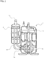
- Fig. 2 is a longitudinal section view showing a compressor and an accumulator of the air-conditioning apparatus.
- Fig. 3 is an enlarged view of a principal part (longitudinal section view) showing the accumulator and the periphery thereof, of the air-conditioning apparatus.
- a solid line arrow indicates a flow direction of refrigerant in a heating operation
- a broken line arrow indicates a flow direction of the refrigerant in a cooling operation.
- the air-conditioning apparatus 100 includes a refrigeration cycle in which a compressor 1 that compresses refrigerant, a four-way valve 6 that switches a circulating direction of the refrigerant depending on whether a cooling operation or a heating operation is performed, an outdoor side heat exchanger 3 that acts as a condenser in the cooling operation and acts as an evaporator in the heating operation, a pressure reducing device 4 (for example, an electronic expansion valve) that depressurizes high-pressure liquid refrigerant into low-pressure two-phase gas-liquid refrigerant, an indoor side heat exchanger 5 that acts as an evaporator in the cooling operation and acts as a condenser in the heating operation, and an accumulator 2 that separates the liquid refrigerant from gas refrigerant and supplies the gas refrigerant to the compressor 1, are connected via a refrigerant pipe.
- a compressor 1 that compresses refrigerant
- a four-way valve 6 that switches a circulating direction of the refrigerant depending
- the refrigeration cycle of the air-conditioning apparatus 100 in the cooling operation includes the compressor 1, the outdoor side heat exchanger 3 acting as the condenser, the pressure reducing device 4, the indoor side heat exchanger 5 acting as the evaporator, and the accumulator 2, which are connected in a loop via the refrigerant pipe.
- the refrigeration cycle of the air-conditioning apparatus 100 includes the compressor 1, the indoor side heat exchanger 5 acting as the condenser, the pressure reducing device 4, the outdoor side heat exchanger 3 acting as the evaporator, and the accumulator 2, which are connected in a loop via the refrigerant pipe.
- the refrigeration cycle configured as above is charged with a non-azeotropic refrigerant mixture containing a refrigerant having a low boiling point and a refrigerant having a high boiling point.
- HFC-R32 is used as the low-boiling point refrigerant
- HFO-1234yf or HFO-1234ze is used as the high-boiling point refrigerant.
- the outdoor side heat exchanger 3 includes an outdoor side fan 9
- the indoor side heat exchanger 5 includes an indoor side fan 8 (for example, cross flow fan).
- the air-conditioning apparatus 100 according to the Embodiment also includes a solenoid valve for dehumidification and reheat 7, to be used in a dehumidifying operation for causing a part of the indoor side heat exchanger 5 to act as the evaporator to thereby dehumidify room air, and causing another part of the indoor side heat exchanger 5 to act as the condenser to thereby heat the dehumidified air and return the heated air to the room space.
- the air-conditioning apparatus 100 includes a compressor suction refrigerant temperature sensor 10 provided in the refrigerant pipe located on the inlet side of the accumulator 2 to detect the temperature of the refrigerant flowing through this point, a compressor discharge refrigerant temperature sensor 11 provided in the pipe located on the discharge side of the compressor 1 to detect the temperature of the refrigerant flowing through this point, an outdoor side heat exchanger refrigerant temperature sensor 12 provided, for example, in an intermediate portion of the outdoor side heat exchanger 3 to detect the temperature of the refrigerant flowing through the outdoor side heat exchanger 3, and an indoor side heat exchanger refrigerant temperature sensor 13 provided, for example, in an intermediate portion of the indoor side heat exchanger 5 to detect the temperature of the refrigerant flowing through the indoor side heat exchanger 5.
- a compressor suction refrigerant temperature sensor 10 provided in the refrigerant pipe located on the inlet side of the accumulator 2 to detect the temperature of the refrigerant flowing through this point
- a compressor discharge refrigerant temperature sensor 11
- the mentioned sensors, the four-way valve 6, the pressure reducing device 4, the solenoid valve for dehumidification and reheat 7, the indoor side fan 8 and the outdoor side fan 9 are electrically connected to the controller 16.
- the controller 16 is configured so as to receive the values detected by the sensors and to independently control each of the four-way valve 6, the pressure reducing device 4, the solenoid valve for dehumidification and reheat 7, the indoor side fan 8, and the outdoor side fan 9.
- the compressor suction refrigerant temperature sensor 10 the compressor discharge refrigerant temperature sensor 11, the outdoor side heat exchanger refrigerant temperature sensor 12, and the indoor side heat exchanger refrigerant temperature sensor 13 are configured to detect the temperature of the refrigerant pipe, to thereby indirectly detect the temperature of the refrigerant.
- the indoor side heat exchanger refrigerant temperature sensor 13 (sensor that detects the temperature of the refrigerant flowing through the evaporator) operating in the cooling operation
- the outdoor side heat exchanger refrigerant temperature sensor 12 (sensor that detects the temperature of the refrigerant flowing through the evaporator) operating in the heating operation correspond to the first refrigerant temperature sensor in the present invention
- the compressor suction refrigerant temperature sensor 10 corresponds to the second refrigerant temperature sensor in the present invention.
- the compressor 1, the accumulator 2, the outdoor side heat exchanger 3, the pressure reducing device 4, the four-way valve 6, the outdoor side fan 9, the compressor suction refrigerant temperature sensor 10, the compressor discharge refrigerant temperature sensor 11, and the outdoor side heat exchanger refrigerant temperature sensor 12 are located inside an outdoor unit 15.
- the indoor side heat exchanger 5, the solenoid valve for dehumidification and reheat 7, the indoor side fan 8, and the indoor side heat exchanger refrigerant temperature sensor 13 are located inside an indoor unit 14.
- the controller 16 may be provided either in the outdoor unit 15 or in the indoor unit 14, or may be divided into parts to be respectively located in the outdoor unit 15 and the indoor unit 14.
- a suction port 1a of the compressor 1 and the accumulator 2 are connected to each other via a suction pipe 21.
- the compressor 1 according to the Embodiment is a high-pressure type compressor that discharges the refrigerant compressed by a compression mechanism unit 1b into a sealed container 1c.
- the compressor 1 includes two rotary compression mechanism units 1b. Accordingly, in the Embodiment the suction ports of the respective compression mechanism units 1b are each connected to the accumulator 2 via the suction pipes 21, in other words two suction pipes 21 are provided.
- the configuration of the compression mechanism unit 1b of the compressor 1 is not limited to the rotary type, and also the number of compression mechanism units 1b is not limited to two.
- An end portion of the suction pipe 21 connected to the accumulator 2 is formed so as to extend into the accumulator 2.
- an L-shaped pipe is employed as the suction pipe 21 in the Embodiment, and the end portion of the suction pipe 21 on the side of the accumulator 2 extends upwardly into the accumulator 2 through the bottom portion thereof.
- an oil return hole 19 is provided in a portion of the suction pipe 21 located inside the accumulator 2, at a position higher than a central portion of the accumulator 2.
- the air-conditioning apparatus 100 is configured to cause the refrigerant of which the quality is less than 1 to flow into the accumulator 2 through an accumulator suction pipe 18, to thereby store the liquid refrigerant in the accumulator 2. Accordingly, it is preferable that the oil return hole 19 is formed at the position higher than the central portion of the accumulator 2.
- the air-conditioning apparatus 100 configured as above works as described hereunder.
- the liquid refrigerant which has flowed out of the outdoor side heat exchanger 3 is depressurized upon passing through the pressure reducing device 4 thereby turning into low-pressure two-phase gas-liquid refrigerant, and flows into the indoor side heat exchanger 5.
- the indoor side heat exchanger 5 by driving the indoor side fan 8 provided in the air path of the room air, the room air exchanges heat with the refrigerant during passing through between fins and tubes (heat transfer pipe) of the indoor side heat exchanger 5, so that the air blown into the room is cooled.
- the two-phase gas-liquid refrigerant is evaporated by removing heat from the room air in the form of evaporation latent heat.
- the controller 16 controls the opening degree of the pressure reducing device 4 so as to make the quality of the refrigerant flowing into the accumulator 2 less than 1, in other words so as to allow the two-phase gas-liquid refrigerant to flow into the accumulator 2. Specifically, in the Embodiment, the controller 16 subtracts the value (B degrees Celsius) detected by the indoor side heat exchanger refrigerant temperature sensor 13 attached to the indoor side heat exchanger 5 acting as the evaporator, from the value (A degrees Celsius) detected by the compressor suction refrigerant temperature sensor 10 provided on the suction side of the accumulator 2, thereby obtaining a degree of superheat (A-B).
- the controller 16 controls the opening degree of the pressure reducing device 4 so as to make the degree of superheat (A-B) less than 0 degrees Celsius.
- the temperature of the non-azeotropic refrigerant mixture of a wet state (two-phase gas-liquid) gradually decreases during the evaporation. Therefore, making the degree of superheat (A-B) less than 0 degrees Celsius allows the quality of the refrigerant flowing into the accumulator 2 to be less than 1.
- the refrigerant of which the quality is less than 1, or the two-phase gas-liquid refrigerant, is separated into liquid refrigerant and gas refrigerant, in the accumulator 2.
- the non-azeotropic refrigerant mixture is employed, more specifically when a refrigerant mixture containing HFC-R32 (boiling point: -58.3 degrees Celsius) and HFO-1234yf (boiling point: -29 degrees Celsius), or a refrigerant mixture containing HFC-R32 and HFO-1234ze (boiling point: -19 degrees Celsius) is employed, the refrigerant of the higher boiling point can be stored in the accumulator 2 as liquid refrigerant 20 owing to the physical property of the refrigerant, and therefore the content of HFC-R32 in the composition of the circulating refrigerant can be made higher than that in the composition of the charged refrigerant.
- the opening degree of the pressure reducing device 4 is controlled so as to make the degree of superheat (A-B) less than, but close to, 0 degrees Celsius. This can increase the content of HFC-R32 in the composition of the circulating refrigerant to a maximal level.
- the oil return hole is formed at a position corresponding to a lower portion of the accumulator. Accordingly, when the conventional air-conditioning apparatus is operated so as to store the liquid refrigerant in the accumulator, as with the air-conditioning apparatus 100 according to the Embodiment, the liquid refrigerant is sucked into the compressor through the oil return hole together with refrigerating machine oil, and therefore loss of suction pressure of the compressor increases and hence the performance of the air-conditioning apparatus is degraded. In the air-conditioning apparatus 100 according to the Embodiment, in contrast, the oil return hole 19 is formed at the position higher than the central portion of the accumulator 2, as stated above.
- the oil return hole 19 may be located above the liquid refrigerant as shown in Fig. 3 . Therefore, in the air-conditioning apparatus 100 according to the Embodiment, only the refrigerating machine oil deposited over the liquid refrigerant is sucked through the oil return hole 19, and hence the liquid refrigerant can be prevented from being sucked through the oil return hole 19. Consequently, degradation in performance of the air-conditioning apparatus 100 can be prevented.
- the gas refrigerant (more strictly, gas refrigerant in which the ratio of HFC-R32 has been increased) is sucked into the compressor 1 through the end portion of the suction pipe 21 on the side of the accumulator 2, thus to be again compressed. Thereafter, through repetition of the phase transition of the refrigerant performed by repeating the similar process, the room space is air-conditioned (cooled) with the air cooled in the indoor side heat exchanger 5.
- the four-way valve 6 is inverted so as to cause the refrigerant to flow in the opposite direction in the refrigeration cycle, with respect to the flow direction in the cooling operation, and the indoor side heat exchanger 5 acts as the condenser and the outdoor side heat exchanger 3 acts as the evaporator, and the room space is air-conditioned (heat) with the air heated in the indoor side heat exchanger 5.
- the controller 16 controls the opening degree of the pressure reducing device 4 so as to make the quality of the refrigerant flowing into the accumulator 2 less than 1, in other words so as to allow the two-phase gas-liquid refrigerant to flow into the accumulator 2. More specifically, the controller 16 subtracts the value (B degrees Celsius) detected by the outdoor side heat exchanger refrigerant temperature sensor 12 attached to the outdoor side heat exchanger 3 acting as the evaporator, from the value (A degrees Celsius) detected by the compressor suction refrigerant temperature sensor 10 provided on the suction side of the accumulator 2, thereby obtaining a degree of superheat (A-B).
- the controller 16 controls the opening degree of the pressure reducing device 4 so as to make the degree of superheat (A-B) less than 0 degrees Celsius.
- A-B degree of superheat
- the configuration of the air-conditioning apparatus 100 according to the Embodiment allows the refrigerant having the higher boiling point among the refrigerants composing the non-azeotropic refrigerant mixture to be stored in the accumulator with priority.
- HFO-1234yf or HFO-1234ze which has higher boiling point, can be stored in the accumulator.
- the air-conditioning apparatus 100 according to the Embodiment can make the content of HFC-R32 in the composition of the circulating refrigerant higher than that in the composition of the charged refrigerant.
- the air-conditioning apparatus 100 according to the Embodiment includes the oil return hole 19 at the position higher than the central portion of the accumulator 2. Accordingly, in the air-conditioning apparatus 100 according to the Embodiment the compressor 1 can be prevented from sucking the liquid refrigerant despite the refrigerant being stored in the accumulator 2, and therefore degradation in performance of the air-conditioning apparatus 100 due to loss of suction pressure of the compressor 1 can be prevented.
- the configuration of the air-conditioning apparatus 100 provides the air-conditioning apparatus 100, which employs the non-azeotropic refrigerant mixture, with high-level performance.
- 1 compressor, 1a suction port, 1b compression mechanism unit, 1c sealed container, 2 accumulator, 3 outdoor side heat exchanger, 4 pressure reducing device, 5 indoor side heat exchanger, 6 four-way valve, 7 solenoid valve for dehumidification and reheat, 8 indoor side fan, 9 outdoor side fan, 10 compressor suction refrigerant temperature sensor, 11 compressor discharge refrigerant temperature sensor, 12 outdoor side heat exchanger refrigerant temperature sensor, 13 indoor side heat exchanger refrigerant temperature sensor, 14 indoor unit, 15 outdoor unit, 16 controller, 18 accumulator suction pipe, 19 oil return hole, 20 liquid refrigerant, 21 suction pipe, 100 air-conditioning apparatus.
Landscapes
- Engineering & Computer Science (AREA)
- Thermal Sciences (AREA)
- Physics & Mathematics (AREA)
- Mechanical Engineering (AREA)
- General Engineering & Computer Science (AREA)
- Chemical & Material Sciences (AREA)
- Analytical Chemistry (AREA)
- Combustion & Propulsion (AREA)
- Power Engineering (AREA)
- Chemical Kinetics & Catalysis (AREA)
- Organic Chemistry (AREA)
- Materials Engineering (AREA)
- Compression-Type Refrigeration Machines With Reversible Cycles (AREA)
- Air Conditioning Control Device (AREA)
Claims (2)
- Klimaanlage (100), umfassend:einen Kältekreislauf, in welchem ein Verdichter (1), ein Kondensator (3), eine Druckminderungseinrichtung (4), ein Verdampfer (5) und ein Akkumulator (2) über ein Kältemittelrohr verbunden sind, wobei der Kältekreislauf mit einem nichtazeotropen Kältemittelgemisch und Kältemaschinenöl beladen ist;eine Steuereinheit (16), die einen Öffnungsgrad der Druckminderungseinrichtung (4) steuert;ein Ansaugrohr (21), welches das Kältemittelrohr ist, das zwischen einer Ansaugöffnung des Verdichters (1) und dem Akkumulator (2) eine Verbindung herstellt, aufweisend einen Endabschnitt an einer Seite des Akkumulators (2), der sich in den Akkumulator (2) hinein erstreckt;einen ersten Kältemitteltemperatursensor (12), der eine Temperatur von den Verdampfer (5) durchströmendem Kältemittel erfasst;dadurch gekennzeichnet, dass die Klimaanlage ferner umfasst:einen zweiten Kältemitteltemperatursensor (10), der eine Temperatur des in den Akkumulator (2) einströmenden Kältemittels erfasst,wobei das Ansaugrohr (21) ein Ölrückführungsloch (19) aufweist, das in einem Abschnitt des Ansaugrohrs (21) ausgebildet ist, der sich innerhalb des Akkumulators (2) befindet, an einer höheren Position als ein Mittelabschnitt des Akkumulators (2), undwobei die Steuereinheit (16) eingerichtet ist, um den Öffnungsgrad der Druckminderungseinrichtung (4) zu steuern, um einen Wert, erhalten durch Subtrahieren eines durch den ersten Kältemitteltemperatursensor (12) detektierten Werts von einem durch den zweiten Kältemitteltemperatursensor detektierten Wert, kleiner als 0 Grad Celsius zu machen, und die Qualität des in den Akkumulator einströmenden Kältemittels geringer als 1 zu machen, um das zweiphasige Gas-Flüssigkeit-Kältemittel, in den Akkumulator (2) einzuströmen zulassen.
- Klimaanlage (100) nach Anspruch 1,
wobei das nichtazeotrope Kältemittelgemisch ein Gemisch aus HFO-1234yf oder HFO-1234ze mit HFC-R32 ist.
Applications Claiming Priority (2)
| Application Number | Priority Date | Filing Date | Title |
|---|---|---|---|
| JP2014077950A JP6120797B2 (ja) | 2014-04-04 | 2014-04-04 | 空気調和機 |
| PCT/JP2015/060452 WO2015152369A1 (ja) | 2014-04-04 | 2015-04-02 | 空気調和機 |
Publications (3)
| Publication Number | Publication Date |
|---|---|
| EP3128264A1 EP3128264A1 (de) | 2017-02-08 |
| EP3128264A4 EP3128264A4 (de) | 2017-10-11 |
| EP3128264B1 true EP3128264B1 (de) | 2018-08-29 |
Family
ID=54240677
Family Applications (1)
| Application Number | Title | Priority Date | Filing Date |
|---|---|---|---|
| EP15772271.1A Active EP3128264B1 (de) | 2014-04-04 | 2015-04-02 | Klimaanlage |
Country Status (7)
| Country | Link |
|---|---|
| US (1) | US9933193B2 (de) |
| EP (1) | EP3128264B1 (de) |
| JP (1) | JP6120797B2 (de) |
| CN (1) | CN106164608B (de) |
| ES (1) | ES2690125T3 (de) |
| RU (1) | RU2666824C2 (de) |
| WO (1) | WO2015152369A1 (de) |
Families Citing this family (9)
| Publication number | Priority date | Publication date | Assignee | Title |
|---|---|---|---|---|
| CN105508203A (zh) * | 2016-01-19 | 2016-04-20 | 珠海格力节能环保制冷技术研究中心有限公司 | 一种增焓部件及具有其的压缩机 |
| JP2018194200A (ja) * | 2017-05-15 | 2018-12-06 | パナソニックIpマネジメント株式会社 | 冷凍サイクル装置およびそれを備えた液体循環装置 |
| CN107436060B (zh) * | 2017-07-04 | 2020-01-14 | 广东美的制冷设备有限公司 | 空调器以及空调器的回液检测装置和方法 |
| US20210055024A1 (en) * | 2017-09-28 | 2021-02-25 | Mitsubishi Electric Corporation | Air-conditioning apparatus |
| CN112739962B (zh) * | 2018-09-28 | 2022-06-03 | 三菱电机株式会社 | 制冷循环装置 |
| JP6911883B2 (ja) * | 2019-03-29 | 2021-07-28 | ダイキン工業株式会社 | 冷凍サイクル装置の性能劣化診断システム |
| DE102020120772A1 (de) * | 2019-09-17 | 2021-03-18 | Hanon Systems | Verdichtermodul |
| KR102875695B1 (ko) * | 2020-03-04 | 2025-10-22 | 엘지전자 주식회사 | 공기조화기 |
| JP7502672B2 (ja) | 2022-09-28 | 2024-06-19 | ダイキン工業株式会社 | 冷凍サイクル装置 |
Family Cites Families (13)
| Publication number | Priority date | Publication date | Assignee | Title |
|---|---|---|---|---|
| JP3284567B2 (ja) * | 1991-10-01 | 2002-05-20 | 松下電器産業株式会社 | アキュムレータ |
| CN1079528C (zh) * | 1993-10-28 | 2002-02-20 | 株式会社日立制作所 | 制冷循环及其控制方法 |
| US5626026A (en) * | 1994-07-21 | 1997-05-06 | Mitsubishi Denki Kabushiki Kaisha | Control-information detecting apparatus for a refrigeration air-conditioner using a non-azeotrope refrigerant |
| JP3054564B2 (ja) * | 1994-11-29 | 2000-06-19 | 三洋電機株式会社 | 空気調和機 |
| JPH09126567A (ja) * | 1995-10-27 | 1997-05-16 | Yamaha Motor Co Ltd | 空調装置 |
| JP3185722B2 (ja) * | 1997-08-20 | 2001-07-11 | 三菱電機株式会社 | 冷凍空調装置および冷凍空調装置の冷媒組成を求める方法 |
| JP3421915B2 (ja) * | 1997-12-19 | 2003-06-30 | 三菱電機株式会社 | 冷凍サイクル |
| JP3051399B1 (ja) * | 1999-03-02 | 2000-06-12 | 松下冷機株式会社 | 冷却装置のアキュムレ―タ |
| JP2000283568A (ja) * | 1999-03-31 | 2000-10-13 | Sanyo Electric Co Ltd | 冷凍装置の制御方法及び冷凍装置 |
| JP2009257744A (ja) | 2008-03-25 | 2009-11-05 | Daikin Ind Ltd | 冷凍装置 |
| JP5502410B2 (ja) * | 2009-01-30 | 2014-05-28 | パナソニック株式会社 | 液体循環式暖房システム |
| JP5713691B2 (ja) * | 2011-01-14 | 2015-05-07 | 日立アプライアンス株式会社 | 冷凍サイクル装置 |
| US10267542B2 (en) * | 2015-04-02 | 2019-04-23 | Carrier Corporation | Wide speed range high-efficiency cold climate heat pump |
-
2014
- 2014-04-04 JP JP2014077950A patent/JP6120797B2/ja not_active Expired - Fee Related
-
2015
- 2015-04-02 US US15/122,252 patent/US9933193B2/en active Active
- 2015-04-02 ES ES15772271.1T patent/ES2690125T3/es active Active
- 2015-04-02 RU RU2016143191A patent/RU2666824C2/ru active
- 2015-04-02 WO PCT/JP2015/060452 patent/WO2015152369A1/ja not_active Ceased
- 2015-04-02 EP EP15772271.1A patent/EP3128264B1/de active Active
- 2015-04-02 CN CN201580017869.XA patent/CN106164608B/zh not_active Expired - Fee Related
Non-Patent Citations (1)
| Title |
|---|
| None * |
Also Published As
| Publication number | Publication date |
|---|---|
| JP2015200431A (ja) | 2015-11-12 |
| CN106164608B (zh) | 2018-11-23 |
| WO2015152369A1 (ja) | 2015-10-08 |
| US9933193B2 (en) | 2018-04-03 |
| EP3128264A1 (de) | 2017-02-08 |
| RU2666824C2 (ru) | 2018-09-12 |
| EP3128264A4 (de) | 2017-10-11 |
| RU2016143191A3 (de) | 2018-05-07 |
| US20160363357A1 (en) | 2016-12-15 |
| CN106164608A (zh) | 2016-11-23 |
| JP6120797B2 (ja) | 2017-04-26 |
| ES2690125T3 (es) | 2018-11-19 |
| RU2016143191A (ru) | 2018-05-07 |
Similar Documents
| Publication | Publication Date | Title |
|---|---|---|
| EP3128264B1 (de) | Klimaanlage | |
| KR101355689B1 (ko) | 공기 조화 장치 및 그 어큐뮬레이터 | |
| US8950202B2 (en) | Heat pump system | |
| EP3885670B1 (de) | Kältekreislaufvorrichtung | |
| US12181168B2 (en) | Air conditioner and control method thereof | |
| EP3312528B1 (de) | Klimaanlage | |
| US12066222B2 (en) | Refrigeration cycle device | |
| WO2016117128A1 (ja) | 空気調和装置 | |
| KR101901540B1 (ko) | 공기 조화 장치 | |
| CN104583684B (zh) | 空调机 | |
| JP2013181736A (ja) | コンテナ用冷凍装置 | |
| JP7067318B2 (ja) | 空気調和機 | |
| JP7092169B2 (ja) | 冷凍サイクル装置 | |
| JP2002243307A (ja) | 空気調和装置 | |
| US11788759B2 (en) | Refrigeration system and heat source unit | |
| WO2017094172A1 (ja) | 空気調和装置 | |
| JP7151282B2 (ja) | 冷凍サイクル装置 | |
| JP5765278B2 (ja) | 室外マルチ型空気調和装置 | |
| JP5999163B2 (ja) | 空気調和装置 | |
| JP2022084919A (ja) | 空気調和機 | |
| EP3217118B1 (de) | Wärmepumpenvorrichtung | |
| WO2017057711A1 (ja) | 冷凍装置 | |
| JP5858022B2 (ja) | 空気調和装置 | |
| JP5831134B2 (ja) | 熱源ユニットセット及び冷凍装置 | |
| JP2020148389A (ja) | 空気調和装置 |
Legal Events
| Date | Code | Title | Description |
|---|---|---|---|
| STAA | Information on the status of an ep patent application or granted ep patent |
Free format text: STATUS: THE INTERNATIONAL PUBLICATION HAS BEEN MADE |
|
| PUAI | Public reference made under article 153(3) epc to a published international application that has entered the european phase |
Free format text: ORIGINAL CODE: 0009012 |
|
| STAA | Information on the status of an ep patent application or granted ep patent |
Free format text: STATUS: REQUEST FOR EXAMINATION WAS MADE |
|
| 17P | Request for examination filed |
Effective date: 20161103 |
|
| AK | Designated contracting states |
Kind code of ref document: A1 Designated state(s): AL AT BE BG CH CY CZ DE DK EE ES FI FR GB GR HR HU IE IS IT LI LT LU LV MC MK MT NL NO PL PT RO RS SE SI SK SM TR |
|
| AX | Request for extension of the european patent |
Extension state: BA ME |
|
| DAV | Request for validation of the european patent (deleted) | ||
| DAX | Request for extension of the european patent (deleted) | ||
| A4 | Supplementary search report drawn up and despatched |
Effective date: 20170908 |
|
| RIC1 | Information provided on ipc code assigned before grant |
Ipc: F25B 43/02 20060101AFI20170904BHEP Ipc: F24F 11/02 20060101ALI20170904BHEP Ipc: F25B 1/00 20060101ALI20170904BHEP |
|
| REG | Reference to a national code |
Ref country code: DE Ref legal event code: R079 Ref document number: 602015015714 Country of ref document: DE Free format text: PREVIOUS MAIN CLASS: F25B0043020000 Ipc: F24F0011300000 |
|
| GRAP | Despatch of communication of intention to grant a patent |
Free format text: ORIGINAL CODE: EPIDOSNIGR1 |
|
| STAA | Information on the status of an ep patent application or granted ep patent |
Free format text: STATUS: GRANT OF PATENT IS INTENDED |
|
| RIC1 | Information provided on ipc code assigned before grant |
Ipc: F24F 11/30 20180101AFI20180219BHEP |
|
| INTG | Intention to grant announced |
Effective date: 20180308 |
|
| GRAS | Grant fee paid |
Free format text: ORIGINAL CODE: EPIDOSNIGR3 |
|
| GRAA | (expected) grant |
Free format text: ORIGINAL CODE: 0009210 |
|
| STAA | Information on the status of an ep patent application or granted ep patent |
Free format text: STATUS: THE PATENT HAS BEEN GRANTED |
|
| AK | Designated contracting states |
Kind code of ref document: B1 Designated state(s): AL AT BE BG CH CY CZ DE DK EE ES FI FR GB GR HR HU IE IS IT LI LT LU LV MC MK MT NL NO PL PT RO RS SE SI SK SM TR |
|
| REG | Reference to a national code |
Ref country code: GB Ref legal event code: FG4D |
|
| REG | Reference to a national code |
Ref country code: CH Ref legal event code: EP |
|
| REG | Reference to a national code |
Ref country code: AT Ref legal event code: REF Ref document number: 1035579 Country of ref document: AT Kind code of ref document: T Effective date: 20180915 |
|
| REG | Reference to a national code |
Ref country code: IE Ref legal event code: FG4D |
|
| REG | Reference to a national code |
Ref country code: DE Ref legal event code: R096 Ref document number: 602015015714 Country of ref document: DE |
|
| REG | Reference to a national code |
Ref country code: SE Ref legal event code: TRGR |
|
| REG | Reference to a national code |
Ref country code: ES Ref legal event code: FG2A Ref document number: 2690125 Country of ref document: ES Kind code of ref document: T3 Effective date: 20181119 |
|
| REG | Reference to a national code |
Ref country code: NL Ref legal event code: MP Effective date: 20180829 |
|
| REG | Reference to a national code |
Ref country code: LT Ref legal event code: MG4D |
|
| PG25 | Lapsed in a contracting state [announced via postgrant information from national office to epo] |
Ref country code: NO Free format text: LAPSE BECAUSE OF FAILURE TO SUBMIT A TRANSLATION OF THE DESCRIPTION OR TO PAY THE FEE WITHIN THE PRESCRIBED TIME-LIMIT Effective date: 20181129 Ref country code: BG Free format text: LAPSE BECAUSE OF FAILURE TO SUBMIT A TRANSLATION OF THE DESCRIPTION OR TO PAY THE FEE WITHIN THE PRESCRIBED TIME-LIMIT Effective date: 20181129 Ref country code: LT Free format text: LAPSE BECAUSE OF FAILURE TO SUBMIT A TRANSLATION OF THE DESCRIPTION OR TO PAY THE FEE WITHIN THE PRESCRIBED TIME-LIMIT Effective date: 20180829 Ref country code: NL Free format text: LAPSE BECAUSE OF FAILURE TO SUBMIT A TRANSLATION OF THE DESCRIPTION OR TO PAY THE FEE WITHIN THE PRESCRIBED TIME-LIMIT Effective date: 20180829 Ref country code: GR Free format text: LAPSE BECAUSE OF FAILURE TO SUBMIT A TRANSLATION OF THE DESCRIPTION OR TO PAY THE FEE WITHIN THE PRESCRIBED TIME-LIMIT Effective date: 20181130 Ref country code: IS Free format text: LAPSE BECAUSE OF FAILURE TO SUBMIT A TRANSLATION OF THE DESCRIPTION OR TO PAY THE FEE WITHIN THE PRESCRIBED TIME-LIMIT Effective date: 20181229 Ref country code: FI Free format text: LAPSE BECAUSE OF FAILURE TO SUBMIT A TRANSLATION OF THE DESCRIPTION OR TO PAY THE FEE WITHIN THE PRESCRIBED TIME-LIMIT Effective date: 20180829 Ref country code: RS Free format text: LAPSE BECAUSE OF FAILURE TO SUBMIT A TRANSLATION OF THE DESCRIPTION OR TO PAY THE FEE WITHIN THE PRESCRIBED TIME-LIMIT Effective date: 20180829 |
|
| REG | Reference to a national code |
Ref country code: AT Ref legal event code: MK05 Ref document number: 1035579 Country of ref document: AT Kind code of ref document: T Effective date: 20180829 |
|
| PG25 | Lapsed in a contracting state [announced via postgrant information from national office to epo] |
Ref country code: HR Free format text: LAPSE BECAUSE OF FAILURE TO SUBMIT A TRANSLATION OF THE DESCRIPTION OR TO PAY THE FEE WITHIN THE PRESCRIBED TIME-LIMIT Effective date: 20180829 Ref country code: AL Free format text: LAPSE BECAUSE OF FAILURE TO SUBMIT A TRANSLATION OF THE DESCRIPTION OR TO PAY THE FEE WITHIN THE PRESCRIBED TIME-LIMIT Effective date: 20180829 Ref country code: LV Free format text: LAPSE BECAUSE OF FAILURE TO SUBMIT A TRANSLATION OF THE DESCRIPTION OR TO PAY THE FEE WITHIN THE PRESCRIBED TIME-LIMIT Effective date: 20180829 |
|
| PG25 | Lapsed in a contracting state [announced via postgrant information from national office to epo] |
Ref country code: EE Free format text: LAPSE BECAUSE OF FAILURE TO SUBMIT A TRANSLATION OF THE DESCRIPTION OR TO PAY THE FEE WITHIN THE PRESCRIBED TIME-LIMIT Effective date: 20180829 Ref country code: RO Free format text: LAPSE BECAUSE OF FAILURE TO SUBMIT A TRANSLATION OF THE DESCRIPTION OR TO PAY THE FEE WITHIN THE PRESCRIBED TIME-LIMIT Effective date: 20180829 Ref country code: AT Free format text: LAPSE BECAUSE OF FAILURE TO SUBMIT A TRANSLATION OF THE DESCRIPTION OR TO PAY THE FEE WITHIN THE PRESCRIBED TIME-LIMIT Effective date: 20180829 Ref country code: CZ Free format text: LAPSE BECAUSE OF FAILURE TO SUBMIT A TRANSLATION OF THE DESCRIPTION OR TO PAY THE FEE WITHIN THE PRESCRIBED TIME-LIMIT Effective date: 20180829 Ref country code: PL Free format text: LAPSE BECAUSE OF FAILURE TO SUBMIT A TRANSLATION OF THE DESCRIPTION OR TO PAY THE FEE WITHIN THE PRESCRIBED TIME-LIMIT Effective date: 20180829 |
|
| PG25 | Lapsed in a contracting state [announced via postgrant information from national office to epo] |
Ref country code: SK Free format text: LAPSE BECAUSE OF FAILURE TO SUBMIT A TRANSLATION OF THE DESCRIPTION OR TO PAY THE FEE WITHIN THE PRESCRIBED TIME-LIMIT Effective date: 20180829 Ref country code: SM Free format text: LAPSE BECAUSE OF FAILURE TO SUBMIT A TRANSLATION OF THE DESCRIPTION OR TO PAY THE FEE WITHIN THE PRESCRIBED TIME-LIMIT Effective date: 20180829 Ref country code: DK Free format text: LAPSE BECAUSE OF FAILURE TO SUBMIT A TRANSLATION OF THE DESCRIPTION OR TO PAY THE FEE WITHIN THE PRESCRIBED TIME-LIMIT Effective date: 20180829 |
|
| REG | Reference to a national code |
Ref country code: DE Ref legal event code: R097 Ref document number: 602015015714 Country of ref document: DE |
|
| PLBE | No opposition filed within time limit |
Free format text: ORIGINAL CODE: 0009261 |
|
| STAA | Information on the status of an ep patent application or granted ep patent |
Free format text: STATUS: NO OPPOSITION FILED WITHIN TIME LIMIT |
|
| 26N | No opposition filed |
Effective date: 20190531 |
|
| PG25 | Lapsed in a contracting state [announced via postgrant information from national office to epo] |
Ref country code: SI Free format text: LAPSE BECAUSE OF FAILURE TO SUBMIT A TRANSLATION OF THE DESCRIPTION OR TO PAY THE FEE WITHIN THE PRESCRIBED TIME-LIMIT Effective date: 20180829 |
|
| REG | Reference to a national code |
Ref country code: CH Ref legal event code: PL |
|
| REG | Reference to a national code |
Ref country code: BE Ref legal event code: MM Effective date: 20190430 |
|
| GBPC | Gb: european patent ceased through non-payment of renewal fee |
Effective date: 20190402 |
|
| PG25 | Lapsed in a contracting state [announced via postgrant information from national office to epo] |
Ref country code: MC Free format text: LAPSE BECAUSE OF FAILURE TO SUBMIT A TRANSLATION OF THE DESCRIPTION OR TO PAY THE FEE WITHIN THE PRESCRIBED TIME-LIMIT Effective date: 20180829 Ref country code: LU Free format text: LAPSE BECAUSE OF NON-PAYMENT OF DUE FEES Effective date: 20190402 |
|
| PG25 | Lapsed in a contracting state [announced via postgrant information from national office to epo] |
Ref country code: LI Free format text: LAPSE BECAUSE OF NON-PAYMENT OF DUE FEES Effective date: 20190430 Ref country code: GB Free format text: LAPSE BECAUSE OF NON-PAYMENT OF DUE FEES Effective date: 20190402 Ref country code: CH Free format text: LAPSE BECAUSE OF NON-PAYMENT OF DUE FEES Effective date: 20190430 |
|
| PG25 | Lapsed in a contracting state [announced via postgrant information from national office to epo] |
Ref country code: BE Free format text: LAPSE BECAUSE OF NON-PAYMENT OF DUE FEES Effective date: 20190430 |
|
| PG25 | Lapsed in a contracting state [announced via postgrant information from national office to epo] |
Ref country code: IE Free format text: LAPSE BECAUSE OF NON-PAYMENT OF DUE FEES Effective date: 20190402 |
|
| PG25 | Lapsed in a contracting state [announced via postgrant information from national office to epo] |
Ref country code: PT Free format text: LAPSE BECAUSE OF FAILURE TO SUBMIT A TRANSLATION OF THE DESCRIPTION OR TO PAY THE FEE WITHIN THE PRESCRIBED TIME-LIMIT Effective date: 20181229 |
|
| PG25 | Lapsed in a contracting state [announced via postgrant information from national office to epo] |
Ref country code: CY Free format text: LAPSE BECAUSE OF FAILURE TO SUBMIT A TRANSLATION OF THE DESCRIPTION OR TO PAY THE FEE WITHIN THE PRESCRIBED TIME-LIMIT Effective date: 20180829 |
|
| PG25 | Lapsed in a contracting state [announced via postgrant information from national office to epo] |
Ref country code: HU Free format text: LAPSE BECAUSE OF FAILURE TO SUBMIT A TRANSLATION OF THE DESCRIPTION OR TO PAY THE FEE WITHIN THE PRESCRIBED TIME-LIMIT; INVALID AB INITIO Effective date: 20150402 Ref country code: MT Free format text: LAPSE BECAUSE OF FAILURE TO SUBMIT A TRANSLATION OF THE DESCRIPTION OR TO PAY THE FEE WITHIN THE PRESCRIBED TIME-LIMIT Effective date: 20180829 |
|
| REG | Reference to a national code |
Ref country code: DE Ref legal event code: R084 Ref document number: 602015015714 Country of ref document: DE |
|
| PG25 | Lapsed in a contracting state [announced via postgrant information from national office to epo] |
Ref country code: MK Free format text: LAPSE BECAUSE OF FAILURE TO SUBMIT A TRANSLATION OF THE DESCRIPTION OR TO PAY THE FEE WITHIN THE PRESCRIBED TIME-LIMIT Effective date: 20180829 |
|
| PGFP | Annual fee paid to national office [announced via postgrant information from national office to epo] |
Ref country code: ES Payment date: 20220504 Year of fee payment: 8 |
|
| REG | Reference to a national code |
Ref country code: ES Ref legal event code: GC2A Effective date: 20220822 |
|
| PGFP | Annual fee paid to national office [announced via postgrant information from national office to epo] |
Ref country code: FR Payment date: 20230309 Year of fee payment: 9 |
|
| PGFP | Annual fee paid to national office [announced via postgrant information from national office to epo] |
Ref country code: TR Payment date: 20230331 Year of fee payment: 9 Ref country code: SE Payment date: 20230227 Year of fee payment: 9 Ref country code: IT Payment date: 20230310 Year of fee payment: 9 |
|
| P01 | Opt-out of the competence of the unified patent court (upc) registered |
Effective date: 20230512 |
|
| PGFP | Annual fee paid to national office [announced via postgrant information from national office to epo] |
Ref country code: DE Payment date: 20230228 Year of fee payment: 9 |
|
| REG | Reference to a national code |
Ref country code: ES Ref legal event code: FD2A Effective date: 20240530 |
|
| PG25 | Lapsed in a contracting state [announced via postgrant information from national office to epo] |
Ref country code: ES Free format text: LAPSE BECAUSE OF NON-PAYMENT OF DUE FEES Effective date: 20230403 |
|
| PG25 | Lapsed in a contracting state [announced via postgrant information from national office to epo] |
Ref country code: ES Free format text: LAPSE BECAUSE OF NON-PAYMENT OF DUE FEES Effective date: 20230403 |
|
| REG | Reference to a national code |
Ref country code: DE Ref legal event code: R119 Ref document number: 602015015714 Country of ref document: DE |
|
| REG | Reference to a national code |
Ref country code: SE Ref legal event code: EUG |
|
| PG25 | Lapsed in a contracting state [announced via postgrant information from national office to epo] |
Ref country code: DE Free format text: LAPSE BECAUSE OF NON-PAYMENT OF DUE FEES Effective date: 20241105 |
|
| PG25 | Lapsed in a contracting state [announced via postgrant information from national office to epo] |
Ref country code: FR Free format text: LAPSE BECAUSE OF NON-PAYMENT OF DUE FEES Effective date: 20240430 |
|
| PG25 | Lapsed in a contracting state [announced via postgrant information from national office to epo] |
Ref country code: FR Free format text: LAPSE BECAUSE OF NON-PAYMENT OF DUE FEES Effective date: 20240430 Ref country code: DE Free format text: LAPSE BECAUSE OF NON-PAYMENT OF DUE FEES Effective date: 20241105 |
|
| PG25 | Lapsed in a contracting state [announced via postgrant information from national office to epo] |
Ref country code: IT Free format text: LAPSE BECAUSE OF NON-PAYMENT OF DUE FEES Effective date: 20240402 |
|
| PG25 | Lapsed in a contracting state [announced via postgrant information from national office to epo] |
Ref country code: SE Free format text: LAPSE BECAUSE OF NON-PAYMENT OF DUE FEES Effective date: 20240403 |