EP3124332B1 - Procédé de fabrication d'élément structural de véhicule - Google Patents
Procédé de fabrication d'élément structural de véhicule Download PDFInfo
- Publication number
- EP3124332B1 EP3124332B1 EP14886797.1A EP14886797A EP3124332B1 EP 3124332 B1 EP3124332 B1 EP 3124332B1 EP 14886797 A EP14886797 A EP 14886797A EP 3124332 B1 EP3124332 B1 EP 3124332B1
- Authority
- EP
- European Patent Office
- Prior art keywords
- vehicle
- extruded material
- side plates
- width dimension
- side plate
- Prior art date
- Legal status (The legal status is an assumption and is not a legal conclusion. Google has not performed a legal analysis and makes no representation as to the accuracy of the status listed.)
- Not-in-force
Links
Images


Classifications
-
- B—PERFORMING OPERATIONS; TRANSPORTING
- B21—MECHANICAL METAL-WORKING WITHOUT ESSENTIALLY REMOVING MATERIAL; PUNCHING METAL
- B21D—WORKING OR PROCESSING OF SHEET METAL OR METAL TUBES, RODS OR PROFILES WITHOUT ESSENTIALLY REMOVING MATERIAL; PUNCHING METAL
- B21D47/00—Making rigid structural elements or units, e.g. honeycomb structures
- B21D47/01—Making rigid structural elements or units, e.g. honeycomb structures beams or pillars
- B21D47/02—Making rigid structural elements or units, e.g. honeycomb structures beams or pillars by expanding
-
- B—PERFORMING OPERATIONS; TRANSPORTING
- B62—LAND VEHICLES FOR TRAVELLING OTHERWISE THAN ON RAILS
- B62D—MOTOR VEHICLES; TRAILERS
- B62D21/00—Understructures, i.e. chassis frame on which a vehicle body may be mounted
- B62D21/15—Understructures, i.e. chassis frame on which a vehicle body may be mounted having impact absorbing means, e.g. a frame designed to permanently or temporarily change shape or dimension upon impact with another body
- B62D21/152—Front or rear frames
-
- B—PERFORMING OPERATIONS; TRANSPORTING
- B21—MECHANICAL METAL-WORKING WITHOUT ESSENTIALLY REMOVING MATERIAL; PUNCHING METAL
- B21C—MANUFACTURE OF METAL SHEETS, WIRE, RODS, TUBES OR PROFILES, OTHERWISE THAN BY ROLLING; AUXILIARY OPERATIONS USED IN CONNECTION WITH METAL-WORKING WITHOUT ESSENTIALLY REMOVING MATERIAL
- B21C23/00—Extruding metal; Impact extrusion
- B21C23/002—Extruding materials of special alloys so far as the composition of the alloy requires or permits special extruding methods of sequences
-
- B—PERFORMING OPERATIONS; TRANSPORTING
- B21—MECHANICAL METAL-WORKING WITHOUT ESSENTIALLY REMOVING MATERIAL; PUNCHING METAL
- B21D—WORKING OR PROCESSING OF SHEET METAL OR METAL TUBES, RODS OR PROFILES WITHOUT ESSENTIALLY REMOVING MATERIAL; PUNCHING METAL
- B21D53/00—Making other particular articles
- B21D53/88—Making other particular articles other parts for vehicles, e.g. cowlings, mudguards
-
- B—PERFORMING OPERATIONS; TRANSPORTING
- B60—VEHICLES IN GENERAL
- B60R—VEHICLES, VEHICLE FITTINGS, OR VEHICLE PARTS, NOT OTHERWISE PROVIDED FOR
- B60R19/00—Wheel guards; Radiator guards, e.g. grilles; Obstruction removers; Fittings damping bouncing force in collisions
- B60R19/02—Bumpers, i.e. impact receiving or absorbing members for protecting vehicles or fending off blows from other vehicles or objects
- B60R19/18—Bumpers, i.e. impact receiving or absorbing members for protecting vehicles or fending off blows from other vehicles or objects characterised by the cross-section; Means within the bumper to absorb impact
-
- B—PERFORMING OPERATIONS; TRANSPORTING
- B62—LAND VEHICLES FOR TRAVELLING OTHERWISE THAN ON RAILS
- B62D—MOTOR VEHICLES; TRAILERS
- B62D25/00—Superstructure or monocoque structure sub-units; Parts or details thereof not otherwise provided for
- B62D25/08—Front or rear portions
- B62D25/082—Engine compartments
-
- B—PERFORMING OPERATIONS; TRANSPORTING
- B62—LAND VEHICLES FOR TRAVELLING OTHERWISE THAN ON RAILS
- B62D—MOTOR VEHICLES; TRAILERS
- B62D29/00—Superstructures, understructures, or sub-units thereof, characterised by the material thereof
- B62D29/008—Superstructures, understructures, or sub-units thereof, characterised by the material thereof predominantly of light alloys, e.g. extruded
-
- B—PERFORMING OPERATIONS; TRANSPORTING
- B60—VEHICLES IN GENERAL
- B60R—VEHICLES, VEHICLE FITTINGS, OR VEHICLE PARTS, NOT OTHERWISE PROVIDED FOR
- B60R19/00—Wheel guards; Radiator guards, e.g. grilles; Obstruction removers; Fittings damping bouncing force in collisions
- B60R19/02—Bumpers, i.e. impact receiving or absorbing members for protecting vehicles or fending off blows from other vehicles or objects
- B60R19/18—Bumpers, i.e. impact receiving or absorbing members for protecting vehicles or fending off blows from other vehicles or objects characterised by the cross-section; Means within the bumper to absorb impact
- B60R2019/1806—Structural beams therefor, e.g. shock-absorbing
- B60R2019/1813—Structural beams therefor, e.g. shock-absorbing made of metal
- B60R2019/182—Structural beams therefor, e.g. shock-absorbing made of metal of light metal, e.g. extruded
Definitions
- the present invention relates to hollow vehicle structure members such as a bumper reinforcement, a floor brace, a tower bar, and a cross member, and more particularly to techniques of manufacturing a vehicle structure member whose width dimension varies in its longitudinal direction by using a hollow extruded material.
- a vehicle structure member is manufactured by using a hollow extruded material that has a pair of side plates and a plurality of connecting plates connecting the side plates together and that has a quadrilateral closed section and a longitudinal shape, such that the width dimension of the vehicle structure member, or the distance between the side plates, varies in the longitudinal direction of the vehicle structure member.
- a method for manufacturing a vehicle structure member described in JP H08-174047 A is an example of such techniques.
- easily bent shape portions such as notches are formed in a pair of connecting plates of a hollow extruded material having a quadrilateral section, and a pair of side plates are pressed by press working so that the connecting plates are partially bent and deformed, whereby the hollow extruded material is thus partially compressed.
- JP H11-192964 A discloses a method for manufacturing a vehicle structure member according to the preamble of claim 1.
- the present invention was developed in view of the above circumstances and it is an object of the present invention to enable even a vehicle structure member having a portion with a relatively small width dimension to be appropriately manufactured by using a hollow extruded material, and to enable the width dimension to be finely set with high accuracy such that space is present between a pair of side plates.
- the invention provides a method for manufacturing a vehicle structure member by using a hollow extruded material that has a pair of side plates and a plurality of connecting plates connecting the side plates together and that has a quadrilateral closed section and a longitudinal shape, such that a width dimension of the vehicle structure member, which is a distance between the side plates, varies in a longitudinal direction of the vehicle structure member, the method characterized by comprising: (a) an extrusion molding step of producing the hollow extruded material with the connecting plates each having a bent shape by extrusion molding; and (b) a widening step of increasing the width dimension by increasing the distance between the side plates partially in the longitudinal direction so as to flatten the connecting plates having the bent shape.
- the invention provides the method recited above, characterized in that in the widening step, a through hole is formed in one of the side plates, a punch is inserted through the through hole, and with the one side plate being held, the punch is moved to contact the other side plate to move the side plates away from each other (separate the side plates further from each other), so that the width dimension is increased.
- a further aspect of the invention provides the method recited above according to the invention, characterized in that the connecting plates each have a perpendicular portion formed in its intermediate portion in an attitude perpendicular to the side plates, and have bends at two positions on both sides of the perpendicular portion.
- the hollow extruded material in which each of the connecting plates has the bent shape is produced by extrusion molding, and the width dimension is increased by increasing the distance between the side plates partially in the longitudinal direction so as to flatten the connecting plates having the bent shape. Accordingly, even the vehicle structure member having a relatively small width dimension can be appropriately manufactured from the hollow extruded material. Moreover, since the width dimension is increased by increasing the distance between the side plates, a widened shape can be finely set with high accuracy when an outer side plate is pressed against a forming surface etc. of a die to increase the width dimension, for example.
- a through hole is formed in one of the side plates, the punch is inserted through the through hole, and with the one side plate being held, the punch is moved to contact the other side plate to move the side plates away from each other, so that the width dimension is increased. Accordingly, the vehicle structure member can be manufactured inexpensively by simple facilities as compared to the case where the hollow extruded material is widened by hydroforming etc.
- the connecting plates each have the perpendicular portion formed in its intermediate portion in an attitude perpendicular to the side plates, and have the bends at two positions on both sides of the perpendicular portion. Accordingly, a change in angle at each bend which is caused by the widening process is smaller than in the case of L-shaped connecting plates having a bend at only one position. This reduces damage that is caused by work hardening etc. at the time the connecting plates are extended and deformed, and more appropriately reduces cracking, breakage, etc. Moreover, each of the connecting plates has the perpendicular portion formed in an attitude perpendicular to the side plates.
- the load when a load is applied such that the side plates are moved toward each other in the event of collision of the vehicle, for example, the load can be appropriately received by the perpendicular portions and appropriately absorbed by deformation of the perpendicular portions to alleviate the shock.
- the present invention is preferably applied to manufacturing of a hollow vehicle structure member such as a vehicle bumper reinforcement, a floor brace, a tower bar, and a cross member by using a hollow extruded material.
- the hollow extruded material is an extruded material having a quadrilateral tubular shape and made of aluminum, an aluminum alloy, or other metals.
- the connecting plates include a pair of outer connecting plates that together with the pair of side plates form the quadrilateral closed section.
- a rib (partition wall) for reinforcement etc. may be provided as the connecting plate in the hollow extruded material so as to be parallel to a longitudinal direction of the hollow extruded material.
- Flanges extending outward may be formed on both sides of at least one of the pair of side plates. In the widening step, the other side plate may be moved away from the one plate with the flanges being held.
- the pair of side plates be substantially parallel to each other.
- one of the side plates may be tilted with respect to the other as viewed in section perpendicular to the longitudinal direction.
- a portion where the width dimension is to be increased can be in various forms.
- the portion where the width dimension is to be increased may be a longitudinal end of the vehicle structure member, or a middle portion in the longitudinal direction of the vehicle structure member.
- the portion where the width dimension is to be increased is determined as appropriate in accordance with the shape, required strength, etc. of the vehicle structure member.
- the width dimension may be increased at a plurality of positions in the longitudinal direction.
- the bent shape of the connecting plates be such that the connecting plate has the perpendicular portion formed in its intermediate portion in an attitude perpendicular to the pair of side plates and has the bends at two positions on both sides of the perpendicular portion.
- the bent shape of the connecting plates can be in various forms. For example, an L-shaped connecting plate having a bend formed at only one position may be used. Alternatively, the connecting plate may have a curved shape or may have bends at three or more positions.
- the connecting plates having the bent shape are flattened in the widening step. However, it is difficult to make the connecting plates completely flat, and the connecting plates need only be widened so as to reduce the extent to which the connecting plates are bent.
- the pair of side plates are separated further from each other by press working etc.
- the bends of the connecting plates may be pressed and flattened to increase the width dimension of the pair of side plates.
- the pair of side plates may be separated further from each other by press working etc. while pressing and flatting the bends.
- the hollow extruded material may first be bent and formed into a predetermined shape and then subjected to the widening step to partially increase the width dimension.
- a through hole is formed in one side plate, the punch is inserted through the through hole, and the width dimension is increased by press working.
- the width dimension can be increased in various forms.
- the through hole may not be formed and the width dimension may be increased by hydroforming by applying an internal pressure.
- the width dimension may be increased by holding flanges formed on both sides of the pair of side plates and pulling the side plates by press working.
- a slide die etc. may be inserted from an opening at a longitudinal end of the hollow extruded material to separate the pair of side plates further away from each other.
- FIG. 1 is a schematic plan view of a vehicle front bumper reinforcement 10 mounted on a vehicle, as viewed from above.
- This vehicle bumper reinforcement 10 has a longitudinal shape that is long in the lateral direction of the vehicle, or the lateral direction in FIG. 1 , and has a gently curved shape that is curved in the middle of the lateral direction of the vehicle toward the front side of the vehicle, as viewed in plan in FIG. 1 .
- the vehicle bumper reinforcement 10 is fixed to right and left side members 18, or vehicle body-side members, via crash boxes 16 at its both ends in the lateral direction of the vehicle, namely at a pair of tilted ends 12 that are gently tilted rearward toward the vehicle body side.
- the vehicle bumper reinforcement 10 is symmetrical and the right and left crash boxes 16 and the right and left side members 18 are arranged substantially symmetrically.
- a bumper 20 made of a synthetic resin is placed on the outside of the vehicle bumper reinforcement 10, namely on the front side of the vehicle.
- the vehicle bumper reinforcement 10 is an example of the vehicle structure member.
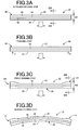
- FIG. 2A is a sectional view of a narrow portion having a relatively narrow width dimension W1, taken along line IA-IA and viewed in the direction of arrows in FIG. 1.
- FIG. 2B is a sectional view of a wide portion having a relatively large width dimension W2, taken along line IB-IB and viewed in the direction of arrows in FIG. 1 .
- the quadrilateral closed section generally having a substantially quadrilateral shape (in the embodiment, a rectangular shape) is formed by an outer side plate 22 located on the outer side (front side) of the vehicle, an inner side plate 24 located on the vehicle body side, and an upper connecting plate 26 and a lower connecting plate 28 which connect the upper ends and lower ends of the outer and inner side plates 22, 24.
- a pair of reinforcing ribs (partition walls) 30, 32 are placed between the upper and lower connecting plates 26, 28 so as to connect the outer and inner side plates 22, 24.
- the vehicle bumper reinforcement 10 is an extrudate of aluminum, and the outer side plate 22, the inner side plate 24, the upper connecting plate 26, the lower connecting plate 28, and the ribs 30, 32 are together formed as a single-piece material.
- This single-piece material has a constant sectional shape substantially the same as the sectional shape shown in FIG. 2A except the tilted ends 12 at both longitudinal ends of the single-piece material, and the distance between the outer and inner side plates 22, 24 is increased in the tilted ends 12 so that the single-piece material has a larger width dimension W2 in the tilted ends 12.
- the ribs 30, 32 together with the upper and lower connecting plates 26, 28 form the plurality of connecting plates.
- the outer side plate 22 and the inner side plate 24 have the shape of a substantially flat plate gently curved in the lateral direction of the vehicle and are arranged substantially parallel to each other in a substantially vertical attitude.
- Each of the upper connecting plate 26, the lower connecting plate 28, and the ribs 30, 32 has a bent shape. Namely, each of the upper connecting plate 26, the lower connecting plate 28, and the ribs 30, 32 has, in its intermediate portion, a substantially horizontal perpendicular portion 34 formed in an attitude substantially perpendicular to the outer and inner side plates 22, 24 and has two bends 36, 38 on both sides of the perpendicular portion 34.
- the upper connecting plate 26 and the lower rib 32 have substantially the same sectional shape.
- the perpendicular portions 34 are displaced so as to be translated downward, and the upper connecting plate 26 and the lower rib 32 have tilted portions on the front and rear sides of the pair of bends 36, 38 which are tilted obliquely upward and connected to the outer and inner side plates 22, 24.
- the lower connecting plate 28 and the upper rib 30 have substantially the same sectional shape.
- the perpendicular portions 34 are displaced so as to be translated upward, and the lower connecting plate 28 and the upper rib 30 have tilted portions on the front and rear sides of the pair of bends 36, 38 which are tilted obliquely downward and connected to the outer and inner side plates 22, 24.
- the narrow portion shown in FIG. 2A and the wide portion shown in FIG. 2B have the different width dimensions W1, W2 due to the difference in extent to which the upper connecting plate 26, the lower connecting plate 28, and the ribs 30, 32 are bent.
- the narrow portion shown in FIG. 2A and the wide portion shown in FIG. 2B have substantially the same length dimension along the bent shape, regardless of the difference between the width dimensions W1, W2. That is, in the wide portion of FIG. 2B , the upper connecting plate 26, the lower connecting plate 28, and the ribs 30, 32 are flattened, so that the bend angle of the bends 36, 38 is reduced, and the outer side plate 22 is moved away from the inner side plate 24 toward the front side of the vehicle accordingly.
- FIG. 5 is a plan view showing an offset collision in which the right front part of the vehicle is caused to crash into a crash barrier 40 having a crash surface 42 at a predetermined vehicle speed V1. This shows a small overlap offset collision in which an overlap (overlap in the lateral direction of the vehicle) between the crash barrier 40 and the vehicle bumper reinforcement 10 is small.
- a load F that is applied by the crash barrier 40 is substantially parallel to the longitudinal direction of the vehicle, and the crash box 16 is appropriately compressively deformed in its axial direction, whereby predetermined shock absorbing performance can be achieved.
- the width dimension between the outer side plate 22 and the inner side plate 24 has a constant value W1 as in a vehicle bumper reinforcement 200 shown in FIG. 11
- a load F is applied toward the inside of the vehicle due to the tilt of the outer side plate 22.
- the applied load F has a component in the lateral direction of the vehicle, and the crash box 16 is subjected to an inward (counterclockwise) moment M toward the inside of the vehicle and tends to buckle inward, which impairs shock absorbing performance.
- each of the upper connecting plate 26, the lower connecting plate 28, and the ribs 30, 32 which connect the outer side plate 22 and the inner side plate 24 together has, in its intermediate portion, the perpendicular portion 34 formed in an attitude perpendicular to the side plates 22, 24. Accordingly, when the outer side plate 22 is moved toward the inner side plate 24 by the applied load F in the event of collision of the vehicle, the applied load F can be appropriately received by the perpendicular portions 34 and appropriately absorbed by deformation of the perpendicular portions 34 to alleviate the shock.
- FIGS. 3A to 3D are plan views corresponding to FIG. 1 .
- FIG. 3A shows an extrusion molding step, in which a linear hollow extruded material 50 having a constant quadrilateral closed section, which is the same as the quadrilateral closed section of FIG.2A , along its entire length is produced by extrusion molding by using an aluminum material.
- FIG. 2A is also a sectional view of the hollow extruded material 50, namely a sectional view taken along line IIIA-IIIA and viewed in the direction of arrows in FIG. 3A .
- FIG. 3B shows a punching step, in which through holes 52 (see FIG. 4 ) are formed by laser machining, press punching, etc. in both longitudinal ends of the inner side plate 24 where the width dimension is to be increased to W2.
- through holes 52 see FIG. 4
- a plurality of through holes 52 separated from each other in the longitudinal direction of the hollow extruded material 50 is formed between the upper connecting plate 26 and the rib 30, between the ribs 30, 32, and between the rib 32 and the lower connecting plate 28.
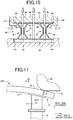
- FIG. 10 is the sectional view corresponding to the section taken along line IV-IV and viewed in the direction of arrows in FIG.
- FIG. 4 showing another embodiment in which flanges 104, 106 extending outward are formed on both sides of the outer and inner side plates 22, 24.
- through holes 52 are formed in a manner similar to that in FIG. 10 .
- Arrows P in FIG. 3B show the positions where the through holes 52 are to be formed.
- FIG. 3C shows a press widening step, in which widened portions 54 corresponding to the wide tilted ends 12 are formed by separating the outer side plate 22 further from the inner side plate 24 in both ends of the hollow extruded material 50 by press deformation so as to increase the width dimension to W2.
- FIG. 4 is a sectional view showing one end of the hollow extruded material 50, specifically illustrating the press widening step. The lateral direction in FIG. 4 corresponds to the longitudinal direction of the hollow extruded material 50.
- the hollow extruded material 50 is first positioned and held by a pair of dies 60, 62, and a slide die 64 is inserted into an opening of the hollow extruded material 50 in the longitudinal direction of the hollow extruded material 50 by a cam mechanism etc. so as to position and hold the inner side plate 24 between the slide die 64 and the die 60.
- a punch 66 is disposed in the die 60 such that the punch 66 can advance and withdraw in its axial direction. The punch 66 is inserted through the through hole 52 so as to contact the inner side surface of the outer side plate 22, and the punch 66 is further advanced to press and deform the outer side plate 22 against a forming surface 68 of the die 62.
- the outer side plate 22 is thus separated further from the inner side plate 24 to increase the width dimension to W2.
- the widened portion 54 having a widened shape corresponding to the forming surface 68, namely having a width dimension continuously gradually changed from W1 to W2, is formed in this manner as shown by a long dashed short dashed line.
- the upper connecting plate 26, the lower connecting plate 28, and the ribs 30, 32 each having the bent shape are extended and flattened from the bent shape as shown in FIG. 2B .
- the width dimension is increased to W2 by this flattening process. Since each of the upper connecting plate 26, the lower connecting plate 28, and the ribs 30, 32 has the bends 36, 38 at two positions on both sides of the perpendicular portion 34, a change in angle at each bend 36, 38 which is caused by the widening process is smaller than in the case where each of the upper connecting plate 26, the lower connecting plate 28, and the ribs 30, 32 has a bend at only one position. This reduces damage that is caused by work hardening etc.
- FIG. 2B is also a sectional view of the widened portion 54 in both ends of the hollow extruded material 50, namely a sectional view taken along line IIIB-IIIB and viewed in the direction of arrows in FIG. 3C .
- the slide die 64 is withdrawn and the dies 60, 62 are opened to take the hollow extruded material 50 having the widened portions 54 with the width dimension W2 formed in both ends out of the dies 60, 62.
- a bending forming step of FIG. 3D the hollow extruded material 50 is bent and formed into a curved shape by press working.
- the intended vehicle bumper reinforcement 10 is thus manufactured.
- the punching step of FIG. 3B and the press widening step of FIG. 3C may be performed after the bending forming step of FIG. 3D .
- the hollow extruded material 50 in which each of the upper connecting plate 26, the lower connecting plate 28, and the ribs 30, 32 which connect the outer and inner side plates 22, 24 together has the bent shape is produced by extrusion molding, and the outer side plate 22 is partially separated further from the inner side plate 24 in both longitudinal ends of the hollow extruded material 50 so as to flatten the upper connecting plate 26, the lower connecting plate 28, and the ribs 30, 32, whereby the width dimension is increased to W2. Accordingly, even the vehicle bumper reinforcement 10 having a relatively small width dimension W1 in its intermediate portion in the longitudinal direction of the vehicle bumper reinforcement 10 can be appropriately manufactured from the hollow extruded material 50 while reducing cracking, breakage, etc.
- the widened shape can be finely set with high accuracy by the forming surface 68.
- the through holes 52 are formed in the inner side plate 24 at the ends of the hollow extruded material 50 which are to be widened, and the punches 66 are inserted through the through holes 52.
- the punches 66 With the inner side plate 24 being held between the slide die 64 and the die 60, the punches 66 are moved to contact the outer side plate 22 to move the outer side plate 22 away from the inner side plate 24 by press working and to increase the width dimension. Accordingly, the vehicle bumper reinforcement 10 can be manufactured inexpensively by simple facilities as compared to the case where the hollow extruded material 50 is widened by hydroforming etc.
- each of the upper connecting plate 26, the lower connecting plate 28, and the ribs 30, 32 which connect the outer and inner side plates 22, 24 together has the bends 36, 38 at two positions on both sides of the perpendicular portion 34, a change in angle at each bend 36, 38 which is caused by the widening process is smaller than in the case of L-shaped connecting plates having a bend at only one position. This reduces damage that is caused by work hardening etc. at the time the upper connecting plate 26, the lower connecting plate 28, and the ribs 30, 32 are extended and deformed, and more appropriately reduces cracking, breakage, etc.
- Each of the upper connecting plate 26, the lower connecting plate 28, and the ribs 30, 32 has the perpendicular portion 34 formed in an attitude perpendicular to the outer and inner side plates 22, 24. Accordingly, when the outer side plate 22 is moved toward the inner side plate 24 by the applied load F in the event of collision of the vehicle, the applied load F can be appropriately received by the perpendicular portions 34 and appropriately absorbed by deformation of the perpendicular portions 34 to alleviate the shock along the entire length of the vehicle bumper reinforcement 10 including the tilted ends 12.
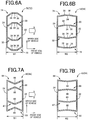
- FIGS. 6A and 6B are sectional views corresponding to FIGS. 2A and 2B .
- a vehicle bumper reinforcement 70 is different from the above embodiment in that the perpendicular portion 34 of an upper connecting plate 74 protrudes upward and the perpendicular portion 34 of a lower connecting plate 76 protrudes downward.
- a hollow extruded material 72 having a narrow sectional shape shown in FIG. 6A is widened in its both longitudinal ends as shown in FIG. 6B in a manner similar to that of the above embodiment.
- Widened portions 54 in which the outer side plate 22 has been bent toward the front side of the vehicle so as to be separated further from the inner side plate 24 are thus formed, and the tilted ends 12 are formed by the widened portions 54.
- the outer side plate 22 may be separated further from the inner side plate 24 and the hollow extruded material 72 may be widened by pressing the perpendicular portions 34 of the upper connecting plate 74 protruding upward and the lower connecting plate 76 protruding downward toward each other.
- FIGS. 7A and 7B are sectional views corresponding to FIGS. 2A and 2B .
- a vehicle bumper reinforcement 80 is different from the above embodiment in that each of an upper connecting plate 84, a lower connecting plate 85, and ribs 86, 87 has a bend 88 at one position near the middle and thus has a substantially L-shaped bent shape in section and does not have the perpendicular portion 34.
- a hollow extruded material 82 having a narrow sectional shape shown in FIG. 7A is widened in its both longitudinal ends as shown in FIG. 7B in a manner similar to that of the above embodiment.
- Widened portions 54 in which the outer side plate 22 has been bent toward the front side of the vehicle so as to be separated further from the inner side plate 24 are thus formed, and the tilted ends 12 are formed by the widened portions 54.
- FIGS. 8A and 8B are sectional views corresponding to FIGS. 2A and 2B .
- a vehicle bumper reinforcement 90 is different from the above embodiment in that the vehicle bumper reinforcement 90 does not have the ribs 30, 32 and has a quadrilateral tubular shape having a simple substantially square section.
- a hollow extruded material 92 having a narrow sectional shape shown in FIG. 8A is widened in its both longitudinal ends as shown in FIG. 8B in a manner similar to that of the above embodiment.
- Widened portions 54 in which the outer side plate 22 has been bent toward the front side of the vehicle so as to be separated further from the inner side plate 24 are thus formed, and the tilted ends 12 are formed by the widened portions 54.
- FIGS. 9A and 9B are sectional views corresponding to FIGS. 2A and 2B .
- a vehicle bumper reinforcement 100 is different from the above embodiment in that flanges 104, 106 extending outward are formed at both ends of the outer and inner side plates 22, 24.
- a hollow extruded material 102 having a narrow sectional shape shown in FIG. 9A is widened in its both longitudinal ends as shown in FIG. 9B .
- Widened portions 54 in which the outer side plate 22 has been bent toward the front side of the vehicle so as to be separated further from the inner side plate 24 are thus formed, and the tilted ends 12 are formed by the widened portions 54.
- FIG. 9A Widened portions 54 in which the outer side plate 22 has been bent toward the front side of the vehicle so as to be separated further from the inner side plate 24 are thus formed, and the tilted ends 12 are formed by the widened portions 54.
- the hollow extruded material 102 may be widened by deformation by pressing the outer side plate 22 against the forming surface 68 by the punches 66 with the flanges 106 on both sides of the inner side plate 24 being held between the die 60 and a pair of slide dies 108, 110.
- the hollow extruded material 102 can be partially widened not only in its longitudinal ends, but in any portion including its intermediate portion in the longitudinal direction of the hollow extruded material 102.
- FIG. 10 is a sectional view corresponding to the section taken along line IV-IV and viewed in the direction of arrows in FIG. 4 .
- Vehicle bumper reinforcement Vehicle structure member 12: Tilted ends 22: Outer side plate 24: Inner side plate 26, 74, 84: Upper connecting plate 28, 76, 85: Lower connecting plate 30, 32, 86, 87: Rib (Connecting plate) 34: Perpendicular portion 36, 38: Bend 50, 72, 82, 92, 102: Hollow extruded material 52: Through hole 54: Widened portion 66: Punch W1, W2: Width dimension
Landscapes
- Engineering & Computer Science (AREA)
- Mechanical Engineering (AREA)
- Chemical & Material Sciences (AREA)
- Combustion & Propulsion (AREA)
- Transportation (AREA)
- Architecture (AREA)
- Structural Engineering (AREA)
- Body Structure For Vehicles (AREA)
- Extrusion Of Metal (AREA)
- Bending Of Plates, Rods, And Pipes (AREA)
Claims (2)
- Procédé de fabrication d'un élément structurel de véhicule (10 ;70 ; 80 ; 90 ; 100) par utilisation d'un matériau extrudé creux (50 ; 72 ; 82 ; 92 ; 102) qui présente une paire de plaques latérales (22, 24) et une pluralité de plaques de raccordement (26, 28, 30, 32 ; 74, 76, 30, 32 ; 84, 85, 86, 87 ; 26, 28 ; 26, 28, 30, 32) raccordant les plaques latérales ensemble et qui présente une section fermée quadrilatérale et une forme longitudinale de sorte qu'une dimension de la largeur (W1, W2) de l'élément structurel de véhicule qui est une distance entre les plaques latérales, varie dans une direction longitudinale de l'élément structurel de véhicule, le procédé étant caractérisé en ce qu'il comprend :une étape de moulage par extrusion de production du matériau extrudé creux avec les plaques de raccordement présentant chacune une forme pliée par moulage par extrusion ; etune étape d'élargissement d'augmentation de la dimension de la largeur par augmentation de la distance entre les plaques latérales partiellement dans la direction longitudinale de manière à aplatir les plaques de raccordement présentant la forme pliée ;caractérisé en ce quedans l'étape d'élargissement, un trou débouchant (52) est formé dans une des plaques latérales (22, 24), un poinçon (66) est inséré au travers du trou débouchant, et avec une plaque latérale (24) qui est maintenue, le poinçon est déplacé pour toucher l'autre plaque latérale (22) afin de déplacer les plaques latérales loin l'une de l'autre de sorte que la dimension de la largeur soit augmentée.
- Procédé selon la revendication 1, dans lequel
les plaques de raccordement (26, 28, 30, 32 ; 74, 76, 30, 32 ; 26, 28 ; 26, 28, 30, 32) présentent chacune une portion perpendiculaire (34) formée dans sa portion intermédiaire dans une disposition perpendiculaire aux plaques latérales (22, 24), et présentent des coudes (36, 38) dans deux positions sur les deux côtés de la portion perpendiculaire.
Applications Claiming Priority (2)
| Application Number | Priority Date | Filing Date | Title |
|---|---|---|---|
| JP2014064554A JP6100191B2 (ja) | 2014-03-26 | 2014-03-26 | 車両用構造部材の製造方法 |
| PCT/JP2014/071108 WO2015145799A1 (fr) | 2014-03-26 | 2014-08-08 | Procédé de fabrication d'élément structural de véhicule |
Publications (3)
| Publication Number | Publication Date |
|---|---|
| EP3124332A1 EP3124332A1 (fr) | 2017-02-01 |
| EP3124332A4 EP3124332A4 (fr) | 2017-11-29 |
| EP3124332B1 true EP3124332B1 (fr) | 2018-12-26 |
Family
ID=54194379
Family Applications (1)
| Application Number | Title | Priority Date | Filing Date |
|---|---|---|---|
| EP14886797.1A Not-in-force EP3124332B1 (fr) | 2014-03-26 | 2014-08-08 | Procédé de fabrication d'élément structural de véhicule |
Country Status (5)
| Country | Link |
|---|---|
| US (1) | US10207310B2 (fr) |
| EP (1) | EP3124332B1 (fr) |
| JP (1) | JP6100191B2 (fr) |
| CN (1) | CN106132781B (fr) |
| WO (1) | WO2015145799A1 (fr) |
Families Citing this family (16)
| Publication number | Priority date | Publication date | Assignee | Title |
|---|---|---|---|---|
| JP2015182704A (ja) * | 2014-03-26 | 2015-10-22 | アイシン精機株式会社 | バンパーリインフォースメント |
| JP6940409B2 (ja) | 2014-11-24 | 2021-09-29 | テッサラクト ストラクチュラル イノベーションズ,インコーポレイテッド | 等減速ユニット |
| US11021120B2 (en) * | 2014-11-24 | 2021-06-01 | Tesseract Structural Innovations, Inc. | Uniform deceleration unit |
| WO2017015482A1 (fr) * | 2015-07-21 | 2017-01-26 | Magna International Inc. | Poutre de pare-chocs |
| DE102015117005A1 (de) * | 2015-10-06 | 2017-04-06 | Benteler Automobiltechnik Gmbh | Crashbox |
| JP2019527138A (ja) | 2016-06-09 | 2019-09-26 | ダイバージェント テクノロジーズ, インコーポレイテッドDivergent Technologies, Inc. | アークおよびノードの設計ならびに製作のためのシステムおよび方法 |
| DE102016114068B3 (de) * | 2016-07-29 | 2017-08-10 | Benteler Automobiltechnik Gmbh | Längsträger aus Mehrlagenstahl |
| CN109890663B (zh) * | 2016-08-26 | 2023-04-14 | 形状集团 | 用于横向弯曲挤压成形铝梁从而温热成型车辆结构件的温热成型工艺和设备 |
| US9994257B2 (en) | 2016-09-07 | 2018-06-12 | Thunder Power New Energy Vehicle Development Company Limited | Specific ribs in longitudinal crash beam |
| WO2018091948A1 (fr) * | 2016-11-18 | 2018-05-24 | Arcelormittal | Poutre de pare-chocs ayant une section transversale en forme de 8 |
| EP3549688A4 (fr) * | 2016-11-30 | 2020-07-29 | Aisin Keikinzoku Co., Ltd. | Élément structural |
| JP6937649B2 (ja) * | 2017-09-29 | 2021-09-22 | アイシン軽金属株式会社 | 衝撃吸収部材及びそれを用いた衝撃吸収構造体 |
| WO2019204350A1 (fr) * | 2018-04-16 | 2019-10-24 | Tesseract Structural Innovations, Inc. | Unité de décélération uniforme |
| US11131358B2 (en) * | 2019-03-25 | 2021-09-28 | GM Global Technology Operations LLC | Energy absorbing beam |
| DE102020114662A1 (de) * | 2020-06-02 | 2021-12-02 | Benteler Automobiltechnik Gmbh | Querträger für ein Stoßfängersystem eines Kraftfahrzeugs sowie Verfahren zur Herstellung eines solchen Querträgers |
| CN116379088B (zh) * | 2023-03-27 | 2023-10-27 | 江苏科技大学 | 二级缓冲吸能薄壁管结构及其制作方法 |
Family Cites Families (15)
| Publication number | Priority date | Publication date | Assignee | Title |
|---|---|---|---|---|
| JP2555750Y2 (ja) * | 1992-04-17 | 1997-11-26 | 日本軽金属株式会社 | 継手部材 |
| JPH0724296A (ja) * | 1993-07-05 | 1995-01-27 | Mitsubishi Heavy Ind Ltd | 粉体加圧供給装置 |
| JP2876985B2 (ja) * | 1994-03-18 | 1999-03-31 | 日本軽金属株式会社 | フレーム素材、フレーム部材、自動車用フレーム材およびフレーム部材の製造方法 |
| JPH0833938A (ja) * | 1994-07-19 | 1996-02-06 | Nippon Light Metal Co Ltd | 中空形材の曲がり部への穿孔方法とバンパーレインフォ ースメントの製造方法 |
| JPH08168814A (ja) * | 1994-12-15 | 1996-07-02 | Furukawa Electric Co Ltd:The | Al合金製自動車構造用中空部材の製造方法 |
| JPH08174047A (ja) * | 1994-12-27 | 1996-07-09 | Nissan Motor Co Ltd | 中空押出形材を用いた自動車用構造部材の成形方法 |
| DE69827720T2 (de) * | 1997-09-02 | 2005-03-31 | Honda Giken Kogyo K.K. | Hohlprofilteile aus Aluminium-Legierung für einen Autokarosserierahmen |
| JPH11192964A (ja) | 1998-01-07 | 1999-07-21 | Nissan Motor Co Ltd | 閉断面部材の製造方法及び閉断面部材 |
| JP3938451B2 (ja) * | 1999-10-18 | 2007-06-27 | 関東自動車工業株式会社 | エネルギー吸収部材 |
| JP2009509775A (ja) * | 2005-10-04 | 2009-03-12 | シエイプ コーポレイション | スタンピングされたシート(stampedsheet)をロール成形する連続プロセス |
| JP2008013124A (ja) * | 2006-07-07 | 2008-01-24 | Kobe Steel Ltd | 対人保護用エネルギー吸収部材 |
| JP2009274654A (ja) * | 2008-05-16 | 2009-11-26 | Calsonic Kansei Corp | 車体強度部材部構造 |
| US9533710B2 (en) * | 2008-09-19 | 2017-01-03 | Ford Global Technologies, Llc | Twelve-cornered strengthening member |
| JP5530168B2 (ja) * | 2009-12-22 | 2014-06-25 | 株式会社ベステックスキョーエイ | パイプ部材の成形方法 |
| JP5864217B2 (ja) * | 2011-11-04 | 2016-02-17 | アイシン精機株式会社 | バンパ補強材 |
-
2014
- 2014-03-26 JP JP2014064554A patent/JP6100191B2/ja not_active Expired - Fee Related
- 2014-08-08 US US15/128,618 patent/US10207310B2/en not_active Expired - Fee Related
- 2014-08-08 WO PCT/JP2014/071108 patent/WO2015145799A1/fr active Application Filing
- 2014-08-08 EP EP14886797.1A patent/EP3124332B1/fr not_active Not-in-force
- 2014-08-08 CN CN201480077469.3A patent/CN106132781B/zh not_active Expired - Fee Related
Non-Patent Citations (1)
| Title |
|---|
| None * |
Also Published As
| Publication number | Publication date |
|---|---|
| CN106132781A (zh) | 2016-11-16 |
| CN106132781B (zh) | 2018-03-02 |
| JP6100191B2 (ja) | 2017-03-22 |
| WO2015145799A1 (fr) | 2015-10-01 |
| JP2015186946A (ja) | 2015-10-29 |
| EP3124332A1 (fr) | 2017-02-01 |
| EP3124332A4 (fr) | 2017-11-29 |
| US20170106429A1 (en) | 2017-04-20 |
| US10207310B2 (en) | 2019-02-19 |
Similar Documents
| Publication | Publication Date | Title |
|---|---|---|
| EP3124332B1 (fr) | Procédé de fabrication d'élément structural de véhicule | |
| TWI574755B (zh) | A method of manufacturing a press-formed member, and a press-forming device | |
| CN102632854B (zh) | 压铸铝合金制溃缩盒 | |
| JP5543756B2 (ja) | 車両用バンパ装置 | |
| CN106994949B (zh) | 防撞梁和用于制造防撞梁的方法 | |
| JP6052479B1 (ja) | プレス成形品の製造方法、プレス成形品及びプレス装置 | |
| WO2015145835A1 (fr) | Renfort de pare-chocs de véhicule | |
| RU2654403C2 (ru) | Образованное штамповкой изделие, автомобильный конструктивный элемент, включающий в себя изделие, способ изготовления и устройство для изготовления образованного штамповкой изделия | |
| US8061034B2 (en) | Method for forming a bumper beam for a motor vehicle | |
| TWI590885B (zh) | A method of manufacturing a press-formed product and a press-formed product, and a manufacturing apparatus of the press-formed product | |
| JP6135829B2 (ja) | プレス成形品の製造方法及びプレス成形品 | |
| WO2016175281A1 (fr) | Appareil de travail à la presse, procédé de travail à la presse et article moulé à la presse | |
| KR20170010832A (ko) | 프레스 성형품의 제조 방법 및 프레스 금형 | |
| WO2016171229A1 (fr) | Procédé permettant de produire un produit moulé à la presse, produit moulé à la presse et dispositif de pressage | |
| EP2551036A1 (fr) | Procédé de fabrication de charnière de portière pour véhicule | |
| WO2017149955A1 (fr) | Procédé de fabrication de produit moulé par compression | |
| WO2018096693A1 (fr) | Procédé de fabrication d'élément métallique | |
| KR102105348B1 (ko) | 프레스 성형 방법 | |
| JP6093156B2 (ja) | 車両用ドアサッシュ及びその製造方法 | |
| JP6094699B2 (ja) | プレス成形品の製造方法、プレス成形品及びプレス装置 | |
| JP5440318B2 (ja) | 車体前部構造 | |
| JP2016203255A (ja) | プレス成形品の製造方法及びプレス装置 | |
| JP6712218B2 (ja) | 自動車のドアビーム | |
| CN206012292U (zh) | 车辆用门防撞梁 | |
| CN114669616A (zh) | 结构部件 |
Legal Events
| Date | Code | Title | Description |
|---|---|---|---|
| STAA | Information on the status of an ep patent application or granted ep patent |
Free format text: STATUS: THE INTERNATIONAL PUBLICATION HAS BEEN MADE |
|
| PUAI | Public reference made under article 153(3) epc to a published international application that has entered the european phase |
Free format text: ORIGINAL CODE: 0009012 |
|
| STAA | Information on the status of an ep patent application or granted ep patent |
Free format text: STATUS: REQUEST FOR EXAMINATION WAS MADE |
|
| 17P | Request for examination filed |
Effective date: 20161011 |
|
| AK | Designated contracting states |
Kind code of ref document: A1 Designated state(s): AL AT BE BG CH CY CZ DE DK EE ES FI FR GB GR HR HU IE IS IT LI LT LU LV MC MK MT NL NO PL PT RO RS SE SI SK SM TR |
|
| AX | Request for extension of the european patent |
Extension state: BA ME |
|
| DAX | Request for extension of the european patent (deleted) | ||
| A4 | Supplementary search report drawn up and despatched |
Effective date: 20171027 |
|
| RIC1 | Information provided on ipc code assigned before grant |
Ipc: B60R 19/04 20060101AFI20171020BHEP Ipc: B62D 25/08 20060101ALI20171020BHEP |
|
| GRAP | Despatch of communication of intention to grant a patent |
Free format text: ORIGINAL CODE: EPIDOSNIGR1 |
|
| STAA | Information on the status of an ep patent application or granted ep patent |
Free format text: STATUS: GRANT OF PATENT IS INTENDED |
|
| INTG | Intention to grant announced |
Effective date: 20180703 |
|
| GRAS | Grant fee paid |
Free format text: ORIGINAL CODE: EPIDOSNIGR3 |
|
| GRAA | (expected) grant |
Free format text: ORIGINAL CODE: 0009210 |
|
| STAA | Information on the status of an ep patent application or granted ep patent |
Free format text: STATUS: THE PATENT HAS BEEN GRANTED |
|
| AK | Designated contracting states |
Kind code of ref document: B1 Designated state(s): AL AT BE BG CH CY CZ DE DK EE ES FI FR GB GR HR HU IE IS IT LI LT LU LV MC MK MT NL NO PL PT RO RS SE SI SK SM TR |
|
| REG | Reference to a national code |
Ref country code: GB Ref legal event code: FG4D |
|
| REG | Reference to a national code |
Ref country code: CH Ref legal event code: EP |
|
| REG | Reference to a national code |
Ref country code: AT Ref legal event code: REF Ref document number: 1080966 Country of ref document: AT Kind code of ref document: T Effective date: 20190115 |
|
| REG | Reference to a national code |
Ref country code: DE Ref legal event code: R096 Ref document number: 602014038896 Country of ref document: DE |
|
| REG | Reference to a national code |
Ref country code: IE Ref legal event code: FG4D |
|
| PG25 | Lapsed in a contracting state [announced via postgrant information from national office to epo] |
Ref country code: LT Free format text: LAPSE BECAUSE OF FAILURE TO SUBMIT A TRANSLATION OF THE DESCRIPTION OR TO PAY THE FEE WITHIN THE PRESCRIBED TIME-LIMIT Effective date: 20181226 Ref country code: BG Free format text: LAPSE BECAUSE OF FAILURE TO SUBMIT A TRANSLATION OF THE DESCRIPTION OR TO PAY THE FEE WITHIN THE PRESCRIBED TIME-LIMIT Effective date: 20190326 Ref country code: NO Free format text: LAPSE BECAUSE OF FAILURE TO SUBMIT A TRANSLATION OF THE DESCRIPTION OR TO PAY THE FEE WITHIN THE PRESCRIBED TIME-LIMIT Effective date: 20190326 Ref country code: HR Free format text: LAPSE BECAUSE OF FAILURE TO SUBMIT A TRANSLATION OF THE DESCRIPTION OR TO PAY THE FEE WITHIN THE PRESCRIBED TIME-LIMIT Effective date: 20181226 Ref country code: LV Free format text: LAPSE BECAUSE OF FAILURE TO SUBMIT A TRANSLATION OF THE DESCRIPTION OR TO PAY THE FEE WITHIN THE PRESCRIBED TIME-LIMIT Effective date: 20181226 Ref country code: FI Free format text: LAPSE BECAUSE OF FAILURE TO SUBMIT A TRANSLATION OF THE DESCRIPTION OR TO PAY THE FEE WITHIN THE PRESCRIBED TIME-LIMIT Effective date: 20181226 |
|
| REG | Reference to a national code |
Ref country code: NL Ref legal event code: MP Effective date: 20181226 |
|
| REG | Reference to a national code |
Ref country code: LT Ref legal event code: MG4D |
|
| PG25 | Lapsed in a contracting state [announced via postgrant information from national office to epo] |
Ref country code: RS Free format text: LAPSE BECAUSE OF FAILURE TO SUBMIT A TRANSLATION OF THE DESCRIPTION OR TO PAY THE FEE WITHIN THE PRESCRIBED TIME-LIMIT Effective date: 20181226 Ref country code: SE Free format text: LAPSE BECAUSE OF FAILURE TO SUBMIT A TRANSLATION OF THE DESCRIPTION OR TO PAY THE FEE WITHIN THE PRESCRIBED TIME-LIMIT Effective date: 20181226 Ref country code: GR Free format text: LAPSE BECAUSE OF FAILURE TO SUBMIT A TRANSLATION OF THE DESCRIPTION OR TO PAY THE FEE WITHIN THE PRESCRIBED TIME-LIMIT Effective date: 20190327 Ref country code: AL Free format text: LAPSE BECAUSE OF FAILURE TO SUBMIT A TRANSLATION OF THE DESCRIPTION OR TO PAY THE FEE WITHIN THE PRESCRIBED TIME-LIMIT Effective date: 20181226 |
|
| REG | Reference to a national code |
Ref country code: AT Ref legal event code: MK05 Ref document number: 1080966 Country of ref document: AT Kind code of ref document: T Effective date: 20181226 |
|
| PG25 | Lapsed in a contracting state [announced via postgrant information from national office to epo] |
Ref country code: NL Free format text: LAPSE BECAUSE OF FAILURE TO SUBMIT A TRANSLATION OF THE DESCRIPTION OR TO PAY THE FEE WITHIN THE PRESCRIBED TIME-LIMIT Effective date: 20181226 |
|
| PG25 | Lapsed in a contracting state [announced via postgrant information from national office to epo] |
Ref country code: ES Free format text: LAPSE BECAUSE OF FAILURE TO SUBMIT A TRANSLATION OF THE DESCRIPTION OR TO PAY THE FEE WITHIN THE PRESCRIBED TIME-LIMIT Effective date: 20181226 Ref country code: IT Free format text: LAPSE BECAUSE OF FAILURE TO SUBMIT A TRANSLATION OF THE DESCRIPTION OR TO PAY THE FEE WITHIN THE PRESCRIBED TIME-LIMIT Effective date: 20181226 Ref country code: CZ Free format text: LAPSE BECAUSE OF FAILURE TO SUBMIT A TRANSLATION OF THE DESCRIPTION OR TO PAY THE FEE WITHIN THE PRESCRIBED TIME-LIMIT Effective date: 20181226 Ref country code: PL Free format text: LAPSE BECAUSE OF FAILURE TO SUBMIT A TRANSLATION OF THE DESCRIPTION OR TO PAY THE FEE WITHIN THE PRESCRIBED TIME-LIMIT Effective date: 20181226 Ref country code: PT Free format text: LAPSE BECAUSE OF FAILURE TO SUBMIT A TRANSLATION OF THE DESCRIPTION OR TO PAY THE FEE WITHIN THE PRESCRIBED TIME-LIMIT Effective date: 20190426 |
|
| PG25 | Lapsed in a contracting state [announced via postgrant information from national office to epo] |
Ref country code: SK Free format text: LAPSE BECAUSE OF FAILURE TO SUBMIT A TRANSLATION OF THE DESCRIPTION OR TO PAY THE FEE WITHIN THE PRESCRIBED TIME-LIMIT Effective date: 20181226 Ref country code: IS Free format text: LAPSE BECAUSE OF FAILURE TO SUBMIT A TRANSLATION OF THE DESCRIPTION OR TO PAY THE FEE WITHIN THE PRESCRIBED TIME-LIMIT Effective date: 20190426 Ref country code: RO Free format text: LAPSE BECAUSE OF FAILURE TO SUBMIT A TRANSLATION OF THE DESCRIPTION OR TO PAY THE FEE WITHIN THE PRESCRIBED TIME-LIMIT Effective date: 20181226 Ref country code: EE Free format text: LAPSE BECAUSE OF FAILURE TO SUBMIT A TRANSLATION OF THE DESCRIPTION OR TO PAY THE FEE WITHIN THE PRESCRIBED TIME-LIMIT Effective date: 20181226 Ref country code: SM Free format text: LAPSE BECAUSE OF FAILURE TO SUBMIT A TRANSLATION OF THE DESCRIPTION OR TO PAY THE FEE WITHIN THE PRESCRIBED TIME-LIMIT Effective date: 20181226 |
|
| REG | Reference to a national code |
Ref country code: DE Ref legal event code: R097 Ref document number: 602014038896 Country of ref document: DE |
|
| PG25 | Lapsed in a contracting state [announced via postgrant information from national office to epo] |
Ref country code: AT Free format text: LAPSE BECAUSE OF FAILURE TO SUBMIT A TRANSLATION OF THE DESCRIPTION OR TO PAY THE FEE WITHIN THE PRESCRIBED TIME-LIMIT Effective date: 20181226 Ref country code: DK Free format text: LAPSE BECAUSE OF FAILURE TO SUBMIT A TRANSLATION OF THE DESCRIPTION OR TO PAY THE FEE WITHIN THE PRESCRIBED TIME-LIMIT Effective date: 20181226 |
|
| PLBE | No opposition filed within time limit |
Free format text: ORIGINAL CODE: 0009261 |
|
| STAA | Information on the status of an ep patent application or granted ep patent |
Free format text: STATUS: NO OPPOSITION FILED WITHIN TIME LIMIT |
|
| 26N | No opposition filed |
Effective date: 20190927 |
|
| PG25 | Lapsed in a contracting state [announced via postgrant information from national office to epo] |
Ref country code: SI Free format text: LAPSE BECAUSE OF FAILURE TO SUBMIT A TRANSLATION OF THE DESCRIPTION OR TO PAY THE FEE WITHIN THE PRESCRIBED TIME-LIMIT Effective date: 20181226 |
|
| PG25 | Lapsed in a contracting state [announced via postgrant information from national office to epo] |
Ref country code: TR Free format text: LAPSE BECAUSE OF FAILURE TO SUBMIT A TRANSLATION OF THE DESCRIPTION OR TO PAY THE FEE WITHIN THE PRESCRIBED TIME-LIMIT Effective date: 20181226 |
|
| PG25 | Lapsed in a contracting state [announced via postgrant information from national office to epo] |
Ref country code: LI Free format text: LAPSE BECAUSE OF NON-PAYMENT OF DUE FEES Effective date: 20190831 Ref country code: MC Free format text: LAPSE BECAUSE OF FAILURE TO SUBMIT A TRANSLATION OF THE DESCRIPTION OR TO PAY THE FEE WITHIN THE PRESCRIBED TIME-LIMIT Effective date: 20181226 Ref country code: LU Free format text: LAPSE BECAUSE OF NON-PAYMENT OF DUE FEES Effective date: 20190808 Ref country code: CH Free format text: LAPSE BECAUSE OF NON-PAYMENT OF DUE FEES Effective date: 20190831 |
|
| REG | Reference to a national code |
Ref country code: BE Ref legal event code: MM Effective date: 20190831 |
|
| PG25 | Lapsed in a contracting state [announced via postgrant information from national office to epo] |
Ref country code: IE Free format text: LAPSE BECAUSE OF NON-PAYMENT OF DUE FEES Effective date: 20190808 |
|
| PG25 | Lapsed in a contracting state [announced via postgrant information from national office to epo] |
Ref country code: BE Free format text: LAPSE BECAUSE OF NON-PAYMENT OF DUE FEES Effective date: 20190831 |
|
| PGFP | Annual fee paid to national office [announced via postgrant information from national office to epo] |
Ref country code: GB Payment date: 20200729 Year of fee payment: 7 Ref country code: FR Payment date: 20200715 Year of fee payment: 7 Ref country code: DE Payment date: 20200729 Year of fee payment: 7 |
|
| PG25 | Lapsed in a contracting state [announced via postgrant information from national office to epo] |
Ref country code: CY Free format text: LAPSE BECAUSE OF FAILURE TO SUBMIT A TRANSLATION OF THE DESCRIPTION OR TO PAY THE FEE WITHIN THE PRESCRIBED TIME-LIMIT Effective date: 20181226 |
|
| PG25 | Lapsed in a contracting state [announced via postgrant information from national office to epo] |
Ref country code: HU Free format text: LAPSE BECAUSE OF FAILURE TO SUBMIT A TRANSLATION OF THE DESCRIPTION OR TO PAY THE FEE WITHIN THE PRESCRIBED TIME-LIMIT; INVALID AB INITIO Effective date: 20140808 Ref country code: MT Free format text: LAPSE BECAUSE OF FAILURE TO SUBMIT A TRANSLATION OF THE DESCRIPTION OR TO PAY THE FEE WITHIN THE PRESCRIBED TIME-LIMIT Effective date: 20181226 |
|
| REG | Reference to a national code |
Ref country code: DE Ref legal event code: R119 Ref document number: 602014038896 Country of ref document: DE |
|
| GBPC | Gb: european patent ceased through non-payment of renewal fee |
Effective date: 20210808 |
|
| PG25 | Lapsed in a contracting state [announced via postgrant information from national office to epo] |
Ref country code: MK Free format text: LAPSE BECAUSE OF FAILURE TO SUBMIT A TRANSLATION OF THE DESCRIPTION OR TO PAY THE FEE WITHIN THE PRESCRIBED TIME-LIMIT Effective date: 20181226 |
|
| PG25 | Lapsed in a contracting state [announced via postgrant information from national office to epo] |
Ref country code: GB Free format text: LAPSE BECAUSE OF NON-PAYMENT OF DUE FEES Effective date: 20210808 Ref country code: FR Free format text: LAPSE BECAUSE OF NON-PAYMENT OF DUE FEES Effective date: 20210831 Ref country code: DE Free format text: LAPSE BECAUSE OF NON-PAYMENT OF DUE FEES Effective date: 20220301 |