EP3123228B1 - Microscope confocal à corrélation d'ouverture - Google Patents
Microscope confocal à corrélation d'ouverture Download PDFInfo
- Publication number
- EP3123228B1 EP3123228B1 EP15712839.8A EP15712839A EP3123228B1 EP 3123228 B1 EP3123228 B1 EP 3123228B1 EP 15712839 A EP15712839 A EP 15712839A EP 3123228 B1 EP3123228 B1 EP 3123228B1
- Authority
- EP
- European Patent Office
- Prior art keywords
- image
- images
- confocal
- focus
- sample
- Prior art date
- Legal status (The legal status is an assumption and is not a legal conclusion. Google has not performed a legal analysis and makes no representation as to the accuracy of the status listed.)
- Active
Links
- 238000000034 method Methods 0.000 claims description 27
- 238000012876 topography Methods 0.000 claims description 11
- 238000005286 illumination Methods 0.000 claims description 6
- 238000009987 spinning Methods 0.000 claims description 6
- 238000001514 detection method Methods 0.000 claims description 4
- 238000004891 communication Methods 0.000 claims description 2
- 230000015654 memory Effects 0.000 claims 2
- 239000002131 composite material Substances 0.000 description 23
- 238000012545 processing Methods 0.000 description 8
- 238000004624 confocal microscopy Methods 0.000 description 4
- 230000003287 optical effect Effects 0.000 description 4
- 238000005259 measurement Methods 0.000 description 3
- 238000011156 evaluation Methods 0.000 description 2
- 238000004364 calculation method Methods 0.000 description 1
- 238000004590 computer program Methods 0.000 description 1
- 238000001218 confocal laser scanning microscopy Methods 0.000 description 1
- 238000006073 displacement reaction Methods 0.000 description 1
- 230000000694 effects Effects 0.000 description 1
- 238000000605 extraction Methods 0.000 description 1
- 238000013213 extrapolation Methods 0.000 description 1
- 230000002452 interceptive effect Effects 0.000 description 1
- 230000005855 radiation Effects 0.000 description 1
- 230000003595 spectral effect Effects 0.000 description 1
- 238000001228 spectrum Methods 0.000 description 1
Images

Classifications
-
- G—PHYSICS
- G02—OPTICS
- G02B—OPTICAL ELEMENTS, SYSTEMS OR APPARATUS
- G02B21/00—Microscopes
- G02B21/0004—Microscopes specially adapted for specific applications
- G02B21/002—Scanning microscopes
- G02B21/0024—Confocal scanning microscopes (CSOMs) or confocal "macroscopes"; Accessories which are not restricted to use with CSOMs, e.g. sample holders
- G02B21/008—Details of detection or image processing, including general computer control
-
- G—PHYSICS
- G02—OPTICS
- G02B—OPTICAL ELEMENTS, SYSTEMS OR APPARATUS
- G02B21/00—Microscopes
- G02B21/0004—Microscopes specially adapted for specific applications
- G02B21/002—Scanning microscopes
- G02B21/0024—Confocal scanning microscopes (CSOMs) or confocal "macroscopes"; Accessories which are not restricted to use with CSOMs, e.g. sample holders
- G02B21/0036—Scanning details, e.g. scanning stages
- G02B21/0044—Scanning details, e.g. scanning stages moving apertures, e.g. Nipkow disks, rotating lens arrays
-
- G—PHYSICS
- G01—MEASURING; TESTING
- G01B—MEASURING LENGTH, THICKNESS OR SIMILAR LINEAR DIMENSIONS; MEASURING ANGLES; MEASURING AREAS; MEASURING IRREGULARITIES OF SURFACES OR CONTOURS
- G01B11/00—Measuring arrangements characterised by the use of optical techniques
- G01B11/24—Measuring arrangements characterised by the use of optical techniques for measuring contours or curvatures
-
- G—PHYSICS
- G02—OPTICS
- G02B—OPTICAL ELEMENTS, SYSTEMS OR APPARATUS
- G02B21/00—Microscopes
- G02B21/0004—Microscopes specially adapted for specific applications
- G02B21/002—Scanning microscopes
- G02B21/0024—Confocal scanning microscopes (CSOMs) or confocal "macroscopes"; Accessories which are not restricted to use with CSOMs, e.g. sample holders
- G02B21/008—Details of detection or image processing, including general computer control
- G02B21/0084—Details of detection or image processing, including general computer control time-scale detection, e.g. strobed, ultra-fast, heterodyne detection
-
- G—PHYSICS
- G02—OPTICS
- G02B—OPTICAL ELEMENTS, SYSTEMS OR APPARATUS
- G02B21/00—Microscopes
- G02B21/06—Means for illuminating specimens
-
- G—PHYSICS
- G02—OPTICS
- G02B—OPTICAL ELEMENTS, SYSTEMS OR APPARATUS
- G02B21/00—Microscopes
- G02B21/36—Microscopes arranged for photographic purposes or projection purposes or digital imaging or video purposes including associated control and data processing arrangements
- G02B21/361—Optical details, e.g. image relay to the camera or image sensor
-
- G—PHYSICS
- G02—OPTICS
- G02B—OPTICAL ELEMENTS, SYSTEMS OR APPARATUS
- G02B21/00—Microscopes
- G02B21/36—Microscopes arranged for photographic purposes or projection purposes or digital imaging or video purposes including associated control and data processing arrangements
- G02B21/365—Control or image processing arrangements for digital or video microscopes
- G02B21/367—Control or image processing arrangements for digital or video microscopes providing an output produced by processing a plurality of individual source images, e.g. image tiling, montage, composite images, depth sectioning, image comparison
Definitions
- the invention relates to a confocal microscope with Aperturkorrelation according to the preamble of claim 1 and a method and software for its operation.
- a major advantage of confocal microscopy is that by rejecting light coming from outside the focal plane, it is possible to obtain a layered image of an object to be observed with improved contrast in the individual layers. This allows the reconstruction of a three-dimensional structure of the object.
- Confocal laser scanning microscopy (Laser Scanning Confocal Microscopy) is probably the most widespread.
- the scanning (pixel-by-pixel) recording of individual points of a sample requires a comparatively long time to produce an overall image.
- the software algorithm for demodulating the raw data of the image must filter the modulated part of the signal and bill multiple images from different mask positions to form an overall image.
- Aperture correlation exploits the speed advantages of image acquisition resulting from the use of a confocal spinning disc. But at the same time the disadvantages avoided when using a confocal spinning disk or eg a laterally scanning slit mask.
- the aperture correlation the interfering cross-talk light that violates the confocality as it passes through another pinhole in the detection than in the exposure is accepted.
- the cross-talk is virtually eliminated by offsetting the non-confocal image. In a confocal spinning disc, this cross-talk would ultimately result in optical artifacts, which are also reflected in the topography to be calculated later.
- the object of the invention is to develop a confocal microscope with aperture correlation to the effect that the creation of a topography or the generation of a batch recording in a simple manner.
- the object is achieved by a microscope having the features of claim 1, by a method having the features of claim 2 and by a computer program having the features of claim 9.
- a confocal microscope initially comprises, in a known manner, a lighting device for illuminating a sample, which can be placed on a stage.
- the illumination device may, for example, be conventional illumination, as is known for wide field microscopes.
- the object table is preferably formed in the horizontal plane and vertically displaceable. Alternatively or additionally, a focus drive may be provided on a lens for focus variation.
- the spinning disk unit comprises a rotatable aperture mask with an optically open first section and at least one structured second section for coding the illumination, as shown for example in US Pat DE 697 04 54 T2 is described.
- the radiation reflected or emitted by the sample is decoded by means of an objective through the aperture mask or a similarly constructed decoder mask and detected by an image acquisition unit.
- a first image (wide field image) is detected by the image recording unit, while a second image (so-called composite image) is decoded and detected through the second section.
- the composite image contains not only the confocal parts but also parts of the wide field image. Therefore, it is usually necessary to subtract the wide field image from the composite image to obtain the confocal image.
- This and further processing steps are carried out to produce the confocal image in the image processing unit with a method according to the invention.
- the invention also encompasses a data processing program with program code means that can be executed in an image processing unit of a generic confocal microscope in order to process the method steps of the method according to the invention in an automated manner.
- the data processing program can also be implemented in an image processing unit of a generic confocal microscope (for example as a firmware update) in order to create topographies of samples.
- a generic confocal microscope for example as a firmware update
- it has a communication interface to a control unit of the microscope in order to read out or control focus positions.
- stack images are suitable, which are recorded at different vertical focus positions.
- the various vertical focus positions can be adjusted by vertical displacement of the stage and / or by focus adjustment of the lens (focus drive). In this way, in particular geometric structures, edges, etc. can be represented with an extended depth of focus.
- the object stage and / or the focus drive are then moved continuously in the vertical direction during the image recording, while the first and second images are continuously recorded alternately.
- the focus position of the object table and / or focus drive which is preferably detected or preset with a position detection means, is then stored as a metadata at the time of the recording.
- This storage can be done for the different types of images in separate or shared stacks.
- a confocal image at a particular focus position always three of the continuously captured images are calculated, with either two first (widefield) or two second (composite) images interpolated to an intermediate image and an image of the other image type (second or first Picture) are computed to a confocal image, which is preferably stored together with the associated focus position as a metadata in an image stack.
- the subtraction direction (composite MINUS Weifield image) must be taken into account.
- the topography of the sample can now be determined in a known manner from the confocal images at different focus positions.
- the topography results from the evaluation of the intensity along the stacking direction. The procedure for this is described, for example, in R. Leach: "Optical Measurement of Surface Topography".
- first and second images are alternately taken in a mixed stack.
- the number of both image types does not have to match.
- first and second images are taken in separate stacks, that is, there is a wide field stack (first images) and a composite stack (second images).
- the recordings can be stored or kept in the stack in the same or opposite direction.
- the second images can be interpolated to the position of the wide field images or vice versa. It is also possible to interpolate first and second images to common new positions or to combine the aforementioned possibilities.
- the one defined here Intermediate image has no relation to such intermediate images known from optical systems. It merely serves as a "stopover" between two or more processing steps.
- At least three images are used to compute the confocal image, with at least two images of the same type and at least one image of the other type required.
- the intermediate image is generated by a suitable interpolation of any type.
- the person skilled in the art can select the interpolation suitable for this purpose. Examples include: polynomial interpolation, spline interpolation of different degrees, nearest-neighbor, Shepard and Akima interpolation. Extrapolations are also possible.
- the vertical adjustment of the object table and / or the focus drive is preferably carried out continuously, but can also be varied in other embodiments of the invention, for example, fixed predetermined focus positions can be approached for image recording with or without the use of a control loop, which are stored with the image data.
- the position data for the focus position can be obtained in all conceivable ways, mechanically by coded systems, optical, acoustic or magnetic or capacitive distance measurement. Likewise, the use of color for obtaining the focus position is possible, as for example in the case of chromatic confocal microscopy (lambda scan).
- the speed of the vertical feed and thus the vertical distance between the images may be the same or different for the composite images and the wide field images be. Alternatively, it is possible to adjust the frame rate of the camera.
- the inventive method can also be used with the chromatic aperture correlation, which in the DE 10 2012 007 045 A1 is described, combined.
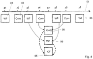
- FIG. 1 to 4 sequences of different variants of the method according to the invention are shown schematically.
- a vertical movement of an object table and / or focus drive is shown as a z-axis 01.
- Various Focus positions z1, z2 ... z7 and za are marked on the z-axis 01.
- wide-field images 02 and composite images 03 are alternately recorded at the respective focus positions z1... Z7 by means of one or more image sensors and stored in an image stack 04 with their respective focus position z1.
- image stack 04 can be used for this storage.
- the focus positions can be approached in a defined manner or detected during a continuous table movement.
- a confocal image 05 at the focus position z2 in the image processing unit two wide field images 02, which were respectively acquired at a different Z position z1 and z3, are interpolated with known image processing means to form a wide field intermediate image 06 at the position z2.
- the confocal image 05 of the focus position z2 is now generated in a known manner by subtracting the Weifield intermediate image 06 from the composite image 03.
- Confocal images 05 are stored with their associated focus positions z2, z4, z6 in a confocal stack image 07.
- a second variant according to Fig. 2 be as an intermediate image for the focus position z3 (or z5)
- the receiving stack 04 is a wide field 02
- the confocal images 05 are now calculated in each case by a subtraction of the weifield image at the focus position z3 (or z5) from the composite intermediate image 08.
- the third variant according to Fig. 3 is a combination of the two previously described. Each shot is used both directly and after interpolation to compute one of the confocal image 05. In this variant, a mixed intermediate image stack 09 can be temporarily stored.
- a confocal image 05 can be generated for a focus position za to which neither a wide field image 02 nor a composite image 03 is present. Such a measure can increase the flexibility of the method.
- the respective next adjacent composite images 03 are interpolated at the positions z4 and z6 to form a composite intermediate image 08 and the adjacent wide-field images at the positions z3 and z5 are interpolated to form a far-field intermediate image 06. From both intermediate images 08.06 the confocal image 05 is calculated by subtraction.
Landscapes
- Physics & Mathematics (AREA)
- General Physics & Mathematics (AREA)
- Chemical & Material Sciences (AREA)
- Analytical Chemistry (AREA)
- Optics & Photonics (AREA)
- Engineering & Computer Science (AREA)
- Multimedia (AREA)
- Computer Vision & Pattern Recognition (AREA)
- General Engineering & Computer Science (AREA)
- Microscoopes, Condenser (AREA)
Claims (9)
- Microscope confocal, comprenant- un dispositif d'éclairage destiné à éclairer un échantillon ;- une unité à disque rotatif, comprenant un masque d'ouverture rotatif pourvu d'une première section ouverte optique et d'une deuxième section structurée destinée au codage de l'éclairage ;- une unité de capture d'image destinée à acquérir une première image (02), qui est associée à la première section, et une deuxième image (03), qui est associée à la deuxième section, à travers le masque d'ouverture ou à travers un masque décodeur ;- une platine porte-objet coulissante verticalement et/ou un mécanisme de mise au point coulissant verticalement pourvu d'un moyen de détection de position destiné à détecter une position verticale (zl ... z7) de la platine porte-objet et/ou du mécanisme de mise au point ;- une unité de traitement d'image destinée à générer une image confocale (05) par calcul des première et deuxième images (02, 03) associées aux sections ; caractérisé en ce que l'unité de capture d'image est conçue pour- capturer des première et deuxième images à des positions verticales différentes ;- mémoriser temporairement les première et deuxième images (02, 03) respectivement avec leur position verticale (zl ... z7) associée ; et- interpoler deux premières (02) ou deux deuxièmes (03) images pour former une image intermédiaire (06 ou 08) et à, avec la deuxième (03) ou la première (02) image, en tenant compte de la position verticale (zl ... z7), générer une image confocale (05) d'un échantillon placé sur la platine porte-objet ;- déterminer la topographie de l'échantillon à partir de plus de deux images confocales à des positions de mise au point différentes.
- Procédé de détermination d'une topographie d'un échantillon au moyen d'un microscope confocal selon la revendication 1, comprenant les étapes suivantes :- déplacement vertical d'une platine porte-objet et/ou d'un mécanisme de mise au point pendant une acquisition en alternance de première et deuxièmes images d'un échantillon placé sur la platine porte-objet, une position de mise au point verticale étant mémorisée pour chaque image sous la forme de métadonnées ;- interpolation de deux premières ou deuxièmes images pour former une image intermédiaire ;- génération d'une image confocale pour une position verticale donnée en calculant l'image intermédiaire avec la première ou la deuxième image à la position concernée ;- détermination de la topographie de l'échantillon à partir de plus de deux images confocales à différentes positions de mise au point.
- Procédé selon la revendication 2, caractérisé en ce que la topographie est formée par une pile constituée de plus de deux images confocales.
- Procédé selon la revendication 2, caractérisé en ce que pour l'interpolation de l'image intermédiaire à une position de mise au point donnée, deux premières ou deuxièmes images des positions de mise au point voisines de la position de mise au point donnée sont utilisées.
- Procédé selon la revendication 2, caractérisé en ce que l'acquisition de premières ou deuxièmes images s'effectue dans des mémoires ou des portions de mémoire séparées.
- Procédé selon la revendication 2, caractérisé en ce que la platine porte-objet se rend à des positions de mise au point verticales prédéfinies.
- Procédé selon la revendication 2, caractérisé en ce que la platine porte-objet est déplacée continuellement pendant la capture de l'image et la position de mise au point associée à chaque image est détectée à l'aide d'un moyen de détection de position.
- Programme de traitement de données destiné à être exécuté dans une unité de traitement de données d'un microscope confocal selon la revendication 1, caractérisé en ce qu'il comprend des instructions de programme codées destinées à mettre en oeuvre un procédé selon l'une des revendications 2 à 7.
- Programme de traitement de données selon la revendication 8, caractérisé en ce qu'il comprend une interface de communication avec une unité de commande du microscope afin de relever ou de commander des positions de mise au point.
Applications Claiming Priority (2)
| Application Number | Priority Date | Filing Date | Title |
|---|---|---|---|
| DE102014004249.9A DE102014004249A1 (de) | 2014-03-24 | 2014-03-24 | Konfokales Mikroskop mit Aperturkorrelation |
| PCT/EP2015/055800 WO2015144557A1 (fr) | 2014-03-24 | 2015-03-19 | Microscope confocal à corrélation d'ouverture |
Publications (2)
| Publication Number | Publication Date |
|---|---|
| EP3123228A1 EP3123228A1 (fr) | 2017-02-01 |
| EP3123228B1 true EP3123228B1 (fr) | 2017-07-12 |
Family
ID=52774196
Family Applications (1)
| Application Number | Title | Priority Date | Filing Date |
|---|---|---|---|
| EP15712839.8A Active EP3123228B1 (fr) | 2014-03-24 | 2015-03-19 | Microscope confocal à corrélation d'ouverture |
Country Status (7)
| Country | Link |
|---|---|
| US (1) | US10754136B2 (fr) |
| EP (1) | EP3123228B1 (fr) |
| JP (1) | JP6277290B2 (fr) |
| CN (1) | CN106104356B (fr) |
| DE (1) | DE102014004249A1 (fr) |
| ES (1) | ES2642675T3 (fr) |
| WO (1) | WO2015144557A1 (fr) |
Families Citing this family (8)
| Publication number | Priority date | Publication date | Assignee | Title |
|---|---|---|---|---|
| ITUB20154591A1 (it) * | 2015-10-12 | 2017-04-12 | Crestoptics S R L | Apparato di microscopia confocale e relativo procedimento di acquisizione ed elaborazione di immagini |
| DE102016103736A1 (de) * | 2016-03-02 | 2017-09-07 | Carl Zeiss Microscopy Gmbh | Verfahren zur Bestimmung einer Höhenlage eines Objekts |
| EP3570087A4 (fr) * | 2017-01-16 | 2020-08-26 | Nikon Corporation | Dispositif de traitement d'image, système de microscope, procédé de traitement d'image, et programme |
| DE102017214189A1 (de) * | 2017-08-15 | 2019-02-21 | Carl Zeiss Microscopy Gmbh | Verfahren zum Betrieb einer Mikroskopieranordnung und Mikroskopieranordnung mit einem ersten Mikroskop und mindestens einem weiteren Mikroskop |
| JP7256604B2 (ja) * | 2018-03-16 | 2023-04-12 | 株式会社ディスコ | 非破壊検出方法 |
| DE102018210606A1 (de) | 2018-06-28 | 2020-01-02 | Carl Zeiss Microscopy Gmbh | Mikroskopisches Abbildungsverfahren unter Verwendung eines Korrekturfaktors |
| DE102018009056A1 (de) * | 2018-11-12 | 2020-05-14 | Carl Zeiss Microscopy Gmbh | Beschleunigte Verfahren und Vorrichtungen für die dreidimensionale Mikroskopie mit strukturierter Beleuchtung |
| DE102019102231A1 (de) * | 2019-01-29 | 2020-08-13 | Senswork Gmbh | Vorrichtung zur Erfassung einer dreidimensionalen Struktur |
Family Cites Families (15)
| Publication number | Priority date | Publication date | Assignee | Title |
|---|---|---|---|---|
| GB9603788D0 (en) | 1996-02-22 | 1996-04-24 | Isis Innovation | Confocal microscope |
| JP3670839B2 (ja) * | 1998-05-18 | 2005-07-13 | オリンパス株式会社 | 共焦点顕微鏡 |
| JP2000258691A (ja) | 1999-03-08 | 2000-09-22 | Olympus Optical Co Ltd | 共焦点顕微鏡 |
| US6426835B1 (en) * | 1999-03-23 | 2002-07-30 | Olympus Optical Co., Ltd. | Confocal microscope |
| US6341035B1 (en) | 1999-07-09 | 2002-01-22 | Olympus Optical Co., Ltd. | Confocal microscope |
| JP2001083432A (ja) | 1999-07-09 | 2001-03-30 | Olympus Optical Co Ltd | 共焦点顕微鏡 |
| TW498152B (en) * | 2000-09-11 | 2002-08-11 | Olympus Optical Co | Confocal microscope |
| US20040257360A1 (en) * | 2001-10-22 | 2004-12-23 | Frank Sieckmann | Method and device for producing light-microscopy, three-dimensional images |
| EP1498759B1 (fr) * | 2003-07-15 | 2006-12-13 | Yokogawa Electric Corporation | Microscope confocale |
| JP4478921B2 (ja) | 2003-08-28 | 2010-06-09 | 横河電機株式会社 | 3次元共焦点レーザ顕微鏡システム |
| WO2008153836A2 (fr) | 2007-05-31 | 2008-12-18 | President And Fellows Of Harvard College | Microscopie confocale d'acquisition à verrouillage de la cible en temps réel (tarc) |
| DE102010015428B4 (de) * | 2010-04-19 | 2015-07-30 | Witec Wissenschaftliche Instrumente Und Technologie Gmbh | Verfahren und Vorrichtung zur Abbildung einer Probenoberfläche |
| DE102011075809A1 (de) * | 2011-05-13 | 2012-11-15 | Carl Zeiss Microimaging Gmbh | Verfahren und Vorrichtung zum Festlegen eines z-Bereiches in einer Probe, in dem ein z-Stapel der Probe mittels eines Mikroskops aufzunehmen ist |
| CN102866492A (zh) * | 2011-07-06 | 2013-01-09 | 黄书伟 | 平衡检测共聚焦显微镜成像系统及其三维影像重建方法 |
| DE102012007045B4 (de) | 2012-04-05 | 2023-03-16 | Carl Zeiss Microscopy Gmbh | Vorrichtung und Verfahren zur Mikroskopie |
-
2014
- 2014-03-24 DE DE102014004249.9A patent/DE102014004249A1/de not_active Ceased
-
2015
- 2015-03-19 CN CN201580014314.XA patent/CN106104356B/zh active Active
- 2015-03-19 JP JP2016571477A patent/JP6277290B2/ja active Active
- 2015-03-19 US US15/127,101 patent/US10754136B2/en active Active
- 2015-03-19 EP EP15712839.8A patent/EP3123228B1/fr active Active
- 2015-03-19 WO PCT/EP2015/055800 patent/WO2015144557A1/fr active Application Filing
- 2015-03-19 ES ES15712839.8T patent/ES2642675T3/es active Active
Non-Patent Citations (1)
| Title |
|---|
| None * |
Also Published As
| Publication number | Publication date |
|---|---|
| CN106104356A (zh) | 2016-11-09 |
| US20170108682A1 (en) | 2017-04-20 |
| JP6277290B2 (ja) | 2018-02-07 |
| DE102014004249A1 (de) | 2015-09-24 |
| ES2642675T3 (es) | 2017-11-17 |
| CN106104356B (zh) | 2018-04-17 |
| JP2017509028A (ja) | 2017-03-30 |
| US10754136B2 (en) | 2020-08-25 |
| WO2015144557A1 (fr) | 2015-10-01 |
| EP3123228A1 (fr) | 2017-02-01 |
Similar Documents
| Publication | Publication Date | Title |
|---|---|---|
| EP3123228B1 (fr) | Microscope confocal à corrélation d'ouverture | |
| DE112011103187B4 (de) | System und Verfahren zur 3D-Lokalisierungsmikroskopie | |
| EP2870500B1 (fr) | Procédé de préparation et de la réalisation de l'enregistrement d'un empilage de vues d'un échantillon suivant des angles d'orientation différents | |
| WO2017013054A1 (fr) | Microscope à feuille de lumière pour la représentation simultanée de plusieurs plans d'objet | |
| DE102013022538B3 (de) | Verfahren zum Erstellen eines Mikroskopbildes und Mikroskopievorrichtung | |
| EP3293558B1 (fr) | Dispositif de détection d'une image stéréo | |
| DE102013021542A1 (de) | Mikroskop und Verfahren zur SPIM Mikroskopie | |
| DE102004047928B4 (de) | Optisches 3D-Messverfahren und Messeinrichtung | |
| DE102010038162A1 (de) | System und Verfahren zur Bildgebung mit verbesserter Tiefenschärfe | |
| DE102014006717A1 (de) | Verfahren zur Erzeugung einer dreidimensionalen Information eines Objektes mit einem Digitalmikroskop und Datenverarbeitungsprogramm zur Abarbeitung des Verfahrens | |
| DE102010038167A1 (de) | System und Verfahren zur Bildgebung mit verbesserter Tiefenschärfe | |
| DE102010017604B4 (de) | Verfahren zum optischen Messen von Strukturen eines Objekts | |
| DE3406578A1 (de) | Automatische brennpunktermittlungsvorrichtung | |
| DE19502472A1 (de) | Verfahren und Vorrichtung zum Aufnehmen eines Objektes | |
| EP3712670A1 (fr) | Procédé de microscopie à balayage haute résolution | |
| DE102009054703A1 (de) | Kalibrierverfahren für ein Mikroskop und Mikroskop mit einer Kalibriereinheit | |
| DE102012102580A1 (de) | Verfahren zum Messen eines Objektes sowie Intraoral-Scanner | |
| DE102019208114B4 (de) | Vorrichtung und Verfahren zur 3D Vermessung von Objektkoordinaten | |
| EP2988157A1 (fr) | Procêdê de reprêsentation d'un êchantillon à l'aide d'un microscope et microscope | |
| DE102013211286A1 (de) | Verfahren zur Vermessung eines Werkstücks mit einem optischen Sensor | |
| DE102018122816B4 (de) | Verfahren und Vorrichtung zum Bestimmen einer Eigenschaft eines Objekts | |
| DE102015110289A1 (de) | Verfahren zur Bestimmung von Messpunkten auf der Oberfläche eines Werkzeugstücks mit einem optischen Sensor | |
| EP3341781B1 (fr) | Ensemble d'éclairage pour un microscope à feuille de lumière | |
| LU102084B1 (de) | Abbildungssystem, insbesondere für eine Kamera | |
| DE102013105102A1 (de) | Verfahren und Vorrichtung zur Bestimmung von Merkmalen an Messobjekten |
Legal Events
| Date | Code | Title | Description |
|---|---|---|---|
| PUAI | Public reference made under article 153(3) epc to a published international application that has entered the european phase |
Free format text: ORIGINAL CODE: 0009012 |
|
| 17P | Request for examination filed |
Effective date: 20161018 |
|
| AK | Designated contracting states |
Kind code of ref document: A1 Designated state(s): AL AT BE BG CH CY CZ DE DK EE ES FI FR GB GR HR HU IE IS IT LI LT LU LV MC MK MT NL NO PL PT RO RS SE SI SK SM TR |
|
| AX | Request for extension of the european patent |
Extension state: BA ME |
|
| RIN1 | Information on inventor provided before grant (corrected) |
Inventor name: LANGHOLZ, NILS Inventor name: DRESCHER, VIKTOR Inventor name: LIPPERT, HELMUT Inventor name: SCHWERDTFEGER, WOLFGANG |
|
| GRAP | Despatch of communication of intention to grant a patent |
Free format text: ORIGINAL CODE: EPIDOSNIGR1 |
|
| DAX | Request for extension of the european patent (deleted) | ||
| INTG | Intention to grant announced |
Effective date: 20170321 |
|
| GRAS | Grant fee paid |
Free format text: ORIGINAL CODE: EPIDOSNIGR3 |
|
| GRAA | (expected) grant |
Free format text: ORIGINAL CODE: 0009210 |
|
| DAV | Request for validation of the european patent (deleted) | ||
| AK | Designated contracting states |
Kind code of ref document: B1 Designated state(s): AL AT BE BG CH CY CZ DE DK EE ES FI FR GB GR HR HU IE IS IT LI LT LU LV MC MK MT NL NO PL PT RO RS SE SI SK SM TR |
|
| REG | Reference to a national code |
Ref country code: GB Ref legal event code: FG4D Free format text: NOT ENGLISH |
|
| REG | Reference to a national code |
Ref country code: CH Ref legal event code: EP |
|
| REG | Reference to a national code |
Ref country code: AT Ref legal event code: REF Ref document number: 908879 Country of ref document: AT Kind code of ref document: T Effective date: 20170715 |
|
| REG | Reference to a national code |
Ref country code: IE Ref legal event code: FG4D Free format text: LANGUAGE OF EP DOCUMENT: GERMAN |
|
| REG | Reference to a national code |
Ref country code: DE Ref legal event code: R096 Ref document number: 502015001434 Country of ref document: DE |
|
| REG | Reference to a national code |
Ref country code: NL Ref legal event code: MP Effective date: 20170712 |
|
| REG | Reference to a national code |
Ref country code: ES Ref legal event code: FG2A Ref document number: 2642675 Country of ref document: ES Kind code of ref document: T3 Effective date: 20171117 |
|
| REG | Reference to a national code |
Ref country code: LT Ref legal event code: MG4D |
|
| PG25 | Lapsed in a contracting state [announced via postgrant information from national office to epo] |
Ref country code: HR Free format text: LAPSE BECAUSE OF FAILURE TO SUBMIT A TRANSLATION OF THE DESCRIPTION OR TO PAY THE FEE WITHIN THE PRESCRIBED TIME-LIMIT Effective date: 20170712 Ref country code: LT Free format text: LAPSE BECAUSE OF FAILURE TO SUBMIT A TRANSLATION OF THE DESCRIPTION OR TO PAY THE FEE WITHIN THE PRESCRIBED TIME-LIMIT Effective date: 20170712 Ref country code: SE Free format text: LAPSE BECAUSE OF FAILURE TO SUBMIT A TRANSLATION OF THE DESCRIPTION OR TO PAY THE FEE WITHIN THE PRESCRIBED TIME-LIMIT Effective date: 20170712 Ref country code: NO Free format text: LAPSE BECAUSE OF FAILURE TO SUBMIT A TRANSLATION OF THE DESCRIPTION OR TO PAY THE FEE WITHIN THE PRESCRIBED TIME-LIMIT Effective date: 20171012 Ref country code: FI Free format text: LAPSE BECAUSE OF FAILURE TO SUBMIT A TRANSLATION OF THE DESCRIPTION OR TO PAY THE FEE WITHIN THE PRESCRIBED TIME-LIMIT Effective date: 20170712 Ref country code: NL Free format text: LAPSE BECAUSE OF FAILURE TO SUBMIT A TRANSLATION OF THE DESCRIPTION OR TO PAY THE FEE WITHIN THE PRESCRIBED TIME-LIMIT Effective date: 20170712 |
|
| PG25 | Lapsed in a contracting state [announced via postgrant information from national office to epo] |
Ref country code: BG Free format text: LAPSE BECAUSE OF FAILURE TO SUBMIT A TRANSLATION OF THE DESCRIPTION OR TO PAY THE FEE WITHIN THE PRESCRIBED TIME-LIMIT Effective date: 20171012 Ref country code: RS Free format text: LAPSE BECAUSE OF FAILURE TO SUBMIT A TRANSLATION OF THE DESCRIPTION OR TO PAY THE FEE WITHIN THE PRESCRIBED TIME-LIMIT Effective date: 20170712 Ref country code: LV Free format text: LAPSE BECAUSE OF FAILURE TO SUBMIT A TRANSLATION OF THE DESCRIPTION OR TO PAY THE FEE WITHIN THE PRESCRIBED TIME-LIMIT Effective date: 20170712 Ref country code: IS Free format text: LAPSE BECAUSE OF FAILURE TO SUBMIT A TRANSLATION OF THE DESCRIPTION OR TO PAY THE FEE WITHIN THE PRESCRIBED TIME-LIMIT Effective date: 20171112 Ref country code: GR Free format text: LAPSE BECAUSE OF FAILURE TO SUBMIT A TRANSLATION OF THE DESCRIPTION OR TO PAY THE FEE WITHIN THE PRESCRIBED TIME-LIMIT Effective date: 20171013 Ref country code: PL Free format text: LAPSE BECAUSE OF FAILURE TO SUBMIT A TRANSLATION OF THE DESCRIPTION OR TO PAY THE FEE WITHIN THE PRESCRIBED TIME-LIMIT Effective date: 20170712 |
|
| REG | Reference to a national code |
Ref country code: DE Ref legal event code: R097 Ref document number: 502015001434 Country of ref document: DE |
|
| PG25 | Lapsed in a contracting state [announced via postgrant information from national office to epo] |
Ref country code: CZ Free format text: LAPSE BECAUSE OF FAILURE TO SUBMIT A TRANSLATION OF THE DESCRIPTION OR TO PAY THE FEE WITHIN THE PRESCRIBED TIME-LIMIT Effective date: 20170712 Ref country code: DK Free format text: LAPSE BECAUSE OF FAILURE TO SUBMIT A TRANSLATION OF THE DESCRIPTION OR TO PAY THE FEE WITHIN THE PRESCRIBED TIME-LIMIT Effective date: 20170712 |
|
| PLBE | No opposition filed within time limit |
Free format text: ORIGINAL CODE: 0009261 |
|
| STAA | Information on the status of an ep patent application or granted ep patent |
Free format text: STATUS: NO OPPOSITION FILED WITHIN TIME LIMIT |
|
| PG25 | Lapsed in a contracting state [announced via postgrant information from national office to epo] |
Ref country code: SK Free format text: LAPSE BECAUSE OF FAILURE TO SUBMIT A TRANSLATION OF THE DESCRIPTION OR TO PAY THE FEE WITHIN THE PRESCRIBED TIME-LIMIT Effective date: 20170712 Ref country code: SM Free format text: LAPSE BECAUSE OF FAILURE TO SUBMIT A TRANSLATION OF THE DESCRIPTION OR TO PAY THE FEE WITHIN THE PRESCRIBED TIME-LIMIT Effective date: 20170712 Ref country code: IT Free format text: LAPSE BECAUSE OF FAILURE TO SUBMIT A TRANSLATION OF THE DESCRIPTION OR TO PAY THE FEE WITHIN THE PRESCRIBED TIME-LIMIT Effective date: 20170712 Ref country code: EE Free format text: LAPSE BECAUSE OF FAILURE TO SUBMIT A TRANSLATION OF THE DESCRIPTION OR TO PAY THE FEE WITHIN THE PRESCRIBED TIME-LIMIT Effective date: 20170712 |
|
| 26N | No opposition filed |
Effective date: 20180413 |
|
| PG25 | Lapsed in a contracting state [announced via postgrant information from national office to epo] |
Ref country code: SI Free format text: LAPSE BECAUSE OF FAILURE TO SUBMIT A TRANSLATION OF THE DESCRIPTION OR TO PAY THE FEE WITHIN THE PRESCRIBED TIME-LIMIT Effective date: 20170712 |
|
| PG25 | Lapsed in a contracting state [announced via postgrant information from national office to epo] |
Ref country code: MT Free format text: LAPSE BECAUSE OF FAILURE TO SUBMIT A TRANSLATION OF THE DESCRIPTION OR TO PAY THE FEE WITHIN THE PRESCRIBED TIME-LIMIT Effective date: 20170712 |
|
| REG | Reference to a national code |
Ref country code: CH Ref legal event code: PL |
|
| PG25 | Lapsed in a contracting state [announced via postgrant information from national office to epo] |
Ref country code: MC Free format text: LAPSE BECAUSE OF FAILURE TO SUBMIT A TRANSLATION OF THE DESCRIPTION OR TO PAY THE FEE WITHIN THE PRESCRIBED TIME-LIMIT Effective date: 20170712 |
|
| REG | Reference to a national code |
Ref country code: BE Ref legal event code: MM Effective date: 20180331 |
|
| REG | Reference to a national code |
Ref country code: IE Ref legal event code: MM4A |
|
| PG25 | Lapsed in a contracting state [announced via postgrant information from national office to epo] |
Ref country code: LU Free format text: LAPSE BECAUSE OF NON-PAYMENT OF DUE FEES Effective date: 20180319 |
|
| PG25 | Lapsed in a contracting state [announced via postgrant information from national office to epo] |
Ref country code: IE Free format text: LAPSE BECAUSE OF NON-PAYMENT OF DUE FEES Effective date: 20180319 |
|
| PG25 | Lapsed in a contracting state [announced via postgrant information from national office to epo] |
Ref country code: CH Free format text: LAPSE BECAUSE OF NON-PAYMENT OF DUE FEES Effective date: 20180331 Ref country code: LI Free format text: LAPSE BECAUSE OF NON-PAYMENT OF DUE FEES Effective date: 20180331 Ref country code: BE Free format text: LAPSE BECAUSE OF NON-PAYMENT OF DUE FEES Effective date: 20180331 |
|
| PG25 | Lapsed in a contracting state [announced via postgrant information from national office to epo] |
Ref country code: FR Free format text: LAPSE BECAUSE OF NON-PAYMENT OF DUE FEES Effective date: 20180331 |
|
| PG25 | Lapsed in a contracting state [announced via postgrant information from national office to epo] |
Ref country code: TR Free format text: LAPSE BECAUSE OF FAILURE TO SUBMIT A TRANSLATION OF THE DESCRIPTION OR TO PAY THE FEE WITHIN THE PRESCRIBED TIME-LIMIT Effective date: 20170712 |
|
| PG25 | Lapsed in a contracting state [announced via postgrant information from national office to epo] |
Ref country code: PT Free format text: LAPSE BECAUSE OF FAILURE TO SUBMIT A TRANSLATION OF THE DESCRIPTION OR TO PAY THE FEE WITHIN THE PRESCRIBED TIME-LIMIT Effective date: 20170712 |
|
| PG25 | Lapsed in a contracting state [announced via postgrant information from national office to epo] |
Ref country code: RO Free format text: LAPSE BECAUSE OF FAILURE TO SUBMIT A TRANSLATION OF THE DESCRIPTION OR TO PAY THE FEE WITHIN THE PRESCRIBED TIME-LIMIT Effective date: 20170712 Ref country code: MK Free format text: LAPSE BECAUSE OF NON-PAYMENT OF DUE FEES Effective date: 20170712 Ref country code: HU Free format text: LAPSE BECAUSE OF FAILURE TO SUBMIT A TRANSLATION OF THE DESCRIPTION OR TO PAY THE FEE WITHIN THE PRESCRIBED TIME-LIMIT; INVALID AB INITIO Effective date: 20150319 Ref country code: CY Free format text: LAPSE BECAUSE OF FAILURE TO SUBMIT A TRANSLATION OF THE DESCRIPTION OR TO PAY THE FEE WITHIN THE PRESCRIBED TIME-LIMIT Effective date: 20170712 |
|
| PG25 | Lapsed in a contracting state [announced via postgrant information from national office to epo] |
Ref country code: AL Free format text: LAPSE BECAUSE OF FAILURE TO SUBMIT A TRANSLATION OF THE DESCRIPTION OR TO PAY THE FEE WITHIN THE PRESCRIBED TIME-LIMIT Effective date: 20170712 |
|
| REG | Reference to a national code |
Ref country code: AT Ref legal event code: MM01 Ref document number: 908879 Country of ref document: AT Kind code of ref document: T Effective date: 20200319 |
|
| PG25 | Lapsed in a contracting state [announced via postgrant information from national office to epo] |
Ref country code: AT Free format text: LAPSE BECAUSE OF NON-PAYMENT OF DUE FEES Effective date: 20200319 |
|
| PGFP | Annual fee paid to national office [announced via postgrant information from national office to epo] |
Ref country code: ES Payment date: 20230529 Year of fee payment: 9 |
|
| PGFP | Annual fee paid to national office [announced via postgrant information from national office to epo] |
Ref country code: DE Payment date: 20240320 Year of fee payment: 10 Ref country code: GB Payment date: 20240320 Year of fee payment: 10 |