EP3122385B2 - Émetteur de faisceau d'électrons - Google Patents
Émetteur de faisceau d'électrons Download PDFInfo
- Publication number
- EP3122385B2 EP3122385B2 EP15715685.2A EP15715685A EP3122385B2 EP 3122385 B2 EP3122385 B2 EP 3122385B2 EP 15715685 A EP15715685 A EP 15715685A EP 3122385 B2 EP3122385 B2 EP 3122385B2
- Authority
- EP
- European Patent Office
- Prior art keywords
- housing
- insert
- annular channel
- electron beam
- beam emitter
- Prior art date
- Legal status (The legal status is an assumption and is not a legal conclusion. Google has not performed a legal analysis and makes no representation as to the accuracy of the status listed.)
- Active
Links
- 238000010894 electron beam technology Methods 0.000 title claims description 54
- 239000011888 foil Substances 0.000 claims description 27
- 230000001954 sterilising effect Effects 0.000 claims description 27
- 238000004659 sterilization and disinfection Methods 0.000 claims description 26
- 238000005192 partition Methods 0.000 claims description 17
- 239000002826 coolant Substances 0.000 claims description 16
- 239000005022 packaging material Substances 0.000 claims description 14
- 239000007788 liquid Substances 0.000 claims description 5
- XLYOFNOQVPJJNP-UHFFFAOYSA-N water Substances O XLYOFNOQVPJJNP-UHFFFAOYSA-N 0.000 claims description 3
- 239000012530 fluid Substances 0.000 claims 1
- 238000004806 packaging method and process Methods 0.000 description 13
- 238000001816 cooling Methods 0.000 description 8
- 239000000463 material Substances 0.000 description 6
- RYGMFSIKBFXOCR-UHFFFAOYSA-N Copper Chemical compound [Cu] RYGMFSIKBFXOCR-UHFFFAOYSA-N 0.000 description 2
- MHAJPDPJQMAIIY-UHFFFAOYSA-N Hydrogen peroxide Chemical compound OO MHAJPDPJQMAIIY-UHFFFAOYSA-N 0.000 description 2
- 239000002800 charge carrier Substances 0.000 description 2
- 229910052802 copper Inorganic materials 0.000 description 2
- 239000010949 copper Substances 0.000 description 2
- 239000003814 drug Substances 0.000 description 2
- 229940079593 drug Drugs 0.000 description 2
- 238000010438 heat treatment Methods 0.000 description 2
- RTAQQCXQSZGOHL-UHFFFAOYSA-N Titanium Chemical compound [Ti] RTAQQCXQSZGOHL-UHFFFAOYSA-N 0.000 description 1
- QCWXUUIWCKQGHC-UHFFFAOYSA-N Zirconium Chemical compound [Zr] QCWXUUIWCKQGHC-UHFFFAOYSA-N 0.000 description 1
- 229910052782 aluminium Inorganic materials 0.000 description 1
- XAGFODPZIPBFFR-UHFFFAOYSA-N aluminium Chemical compound [Al] XAGFODPZIPBFFR-UHFFFAOYSA-N 0.000 description 1
- 238000009833 condensation Methods 0.000 description 1
- 230000005494 condensation Effects 0.000 description 1
- 230000003750 conditioning effect Effects 0.000 description 1
- 238000010276 construction Methods 0.000 description 1
- 230000007423 decrease Effects 0.000 description 1
- 230000001419 dependent effect Effects 0.000 description 1
- 238000009792 diffusion process Methods 0.000 description 1
- 238000005553 drilling Methods 0.000 description 1
- 239000000835 fiber Substances 0.000 description 1
- 238000003780 insertion Methods 0.000 description 1
- 230000037431 insertion Effects 0.000 description 1
- 229910052751 metal Inorganic materials 0.000 description 1
- 239000002184 metal Substances 0.000 description 1
- 150000002739 metals Chemical class 0.000 description 1
- 238000007789 sealing Methods 0.000 description 1
- 239000007787 solid Substances 0.000 description 1
- 239000010936 titanium Substances 0.000 description 1
- 229910052719 titanium Inorganic materials 0.000 description 1
- 238000007704 wet chemistry method Methods 0.000 description 1
- 229910052726 zirconium Inorganic materials 0.000 description 1
Images


Classifications
-
- B—PERFORMING OPERATIONS; TRANSPORTING
- B65—CONVEYING; PACKING; STORING; HANDLING THIN OR FILAMENTARY MATERIAL
- B65B—MACHINES, APPARATUS OR DEVICES FOR, OR METHODS OF, PACKAGING ARTICLES OR MATERIALS; UNPACKING
- B65B55/00—Preserving, protecting or purifying packages or package contents in association with packaging
- B65B55/02—Sterilising, e.g. of complete packages
- B65B55/04—Sterilising wrappers or receptacles prior to, or during, packaging
- B65B55/08—Sterilising wrappers or receptacles prior to, or during, packaging by irradiation
-
- A—HUMAN NECESSITIES
- A61—MEDICAL OR VETERINARY SCIENCE; HYGIENE
- A61L—METHODS OR APPARATUS FOR STERILISING MATERIALS OR OBJECTS IN GENERAL; DISINFECTION, STERILISATION OR DEODORISATION OF AIR; CHEMICAL ASPECTS OF BANDAGES, DRESSINGS, ABSORBENT PADS OR SURGICAL ARTICLES; MATERIALS FOR BANDAGES, DRESSINGS, ABSORBENT PADS OR SURGICAL ARTICLES
- A61L2/00—Methods or apparatus for disinfecting or sterilising materials or objects other than foodstuffs or contact lenses; Accessories therefor
- A61L2/02—Methods or apparatus for disinfecting or sterilising materials or objects other than foodstuffs or contact lenses; Accessories therefor using physical phenomena
- A61L2/08—Radiation
- A61L2/087—Particle radiation, e.g. electron-beam, alpha or beta radiation
-
- A—HUMAN NECESSITIES
- A61—MEDICAL OR VETERINARY SCIENCE; HYGIENE
- A61L—METHODS OR APPARATUS FOR STERILISING MATERIALS OR OBJECTS IN GENERAL; DISINFECTION, STERILISATION OR DEODORISATION OF AIR; CHEMICAL ASPECTS OF BANDAGES, DRESSINGS, ABSORBENT PADS OR SURGICAL ARTICLES; MATERIALS FOR BANDAGES, DRESSINGS, ABSORBENT PADS OR SURGICAL ARTICLES
- A61L2/00—Methods or apparatus for disinfecting or sterilising materials or objects other than foodstuffs or contact lenses; Accessories therefor
- A61L2/02—Methods or apparatus for disinfecting or sterilising materials or objects other than foodstuffs or contact lenses; Accessories therefor using physical phenomena
- A61L2/08—Radiation
-
- A—HUMAN NECESSITIES
- A61—MEDICAL OR VETERINARY SCIENCE; HYGIENE
- A61L—METHODS OR APPARATUS FOR STERILISING MATERIALS OR OBJECTS IN GENERAL; DISINFECTION, STERILISATION OR DEODORISATION OF AIR; CHEMICAL ASPECTS OF BANDAGES, DRESSINGS, ABSORBENT PADS OR SURGICAL ARTICLES; MATERIALS FOR BANDAGES, DRESSINGS, ABSORBENT PADS OR SURGICAL ARTICLES
- A61L2/00—Methods or apparatus for disinfecting or sterilising materials or objects other than foodstuffs or contact lenses; Accessories therefor
- A61L2/26—Accessories or devices or components used for biocidal treatment
- A61L2/28—Devices for testing the effectiveness or completeness of sterilisation, e.g. indicators which change colour
-
- B—PERFORMING OPERATIONS; TRANSPORTING
- B29—WORKING OF PLASTICS; WORKING OF SUBSTANCES IN A PLASTIC STATE IN GENERAL
- B29C—SHAPING OR JOINING OF PLASTICS; SHAPING OF MATERIAL IN A PLASTIC STATE, NOT OTHERWISE PROVIDED FOR; AFTER-TREATMENT OF THE SHAPED PRODUCTS, e.g. REPAIRING
- B29C49/00—Blow-moulding, i.e. blowing a preform or parison to a desired shape within a mould; Apparatus therefor
- B29C49/42—Component parts, details or accessories; Auxiliary operations
- B29C49/4252—Auxiliary operations prior to the blow-moulding operation not otherwise provided for
-
- G—PHYSICS
- G21—NUCLEAR PHYSICS; NUCLEAR ENGINEERING
- G21K—TECHNIQUES FOR HANDLING PARTICLES OR IONISING RADIATION NOT OTHERWISE PROVIDED FOR; IRRADIATION DEVICES; GAMMA RAY OR X-RAY MICROSCOPES
- G21K5/00—Irradiation devices
-
- H—ELECTRICITY
- H01—ELECTRIC ELEMENTS
- H01J—ELECTRIC DISCHARGE TUBES OR DISCHARGE LAMPS
- H01J33/00—Discharge tubes with provision for emergence of electrons or ions from the vessel; Lenard tubes
- H01J33/02—Details
- H01J33/04—Windows
-
- H—ELECTRICITY
- H01—ELECTRIC ELEMENTS
- H01J—ELECTRIC DISCHARGE TUBES OR DISCHARGE LAMPS
- H01J5/00—Details relating to vessels or to leading-in conductors common to two or more basic types of discharge tubes or lamps
- H01J5/02—Vessels; Containers; Shields associated therewith; Vacuum locks
- H01J5/18—Windows permeable to X-rays, gamma-rays, or particles
-
- A—HUMAN NECESSITIES
- A61—MEDICAL OR VETERINARY SCIENCE; HYGIENE
- A61L—METHODS OR APPARATUS FOR STERILISING MATERIALS OR OBJECTS IN GENERAL; DISINFECTION, STERILISATION OR DEODORISATION OF AIR; CHEMICAL ASPECTS OF BANDAGES, DRESSINGS, ABSORBENT PADS OR SURGICAL ARTICLES; MATERIALS FOR BANDAGES, DRESSINGS, ABSORBENT PADS OR SURGICAL ARTICLES
- A61L2202/00—Aspects relating to methods or apparatus for disinfecting or sterilising materials or objects
- A61L2202/20—Targets to be treated
- A61L2202/23—Containers, e.g. vials, bottles, syringes, mail
Definitions
- This invention relates to an electron beam emitter, in particular for sterilization of packaging material, and to a sterilization device, in particular for packaging material.
- Electron irradiation has been considered as a promising alternative for sterilizing purposes for which wet chemistry involving hydrogen peroxide has been the traditional technical platform.
- Known electron beam emitters use an electron generator for emitting charge carriers, such as electrons.
- the electron generator comprises a cathode housing and a filament.
- an electrical current is set through the filament, an electrical resistance of the filament causes the filament to be heated which causes the filament further on to emit a cloud of electrons.
- the electrons leave the housing of the electron beam emitter via an electron exit window. During sterilization, the electron exit window heats up. Cooling methods or cooled electron exit windows are basically known from the prior art, for example through DE 20 2012 103 519 U1 , WO 2009/144114 A1 and EP 1 982 921 B1 .
- the electron beam emitter in particular for sterilization of packaging material, comprises a housing and an insert, wherein the housing comprises a first annular channel for guiding a medium, and wherein the first annular channel at least partially surrounds the insert, wherein the first annular channel is adapted to provide the medium, characterized in that the first annular channel is at least partly formed by the insert.
- the insert is adapted to form part of an electron exit window.
- the insert is comprised in the electron exit window together with a foil element.
- the electron beam emitter is connected or connectable to a power supply unit.
- the power supply unit can also be connected to more than one electron beam emitters.
- the combination of the power supply unit and at least one electron beam emitter is named sterilization device.
- the electron beam emitter comprises an electron generator for emitting charge carriers, such as electrons, along a path.
- the electron generator is generally enclosed in a hermetically sealed vacuum chamber. This vacuum chamber is one part of the aforementioned housing.
- the vacuum chamber is provided according to one or more embodiments with the electron exit window.
- the electron generator comprises a cathode housing and a filament.
- an electron beam is generated by heating the filament.
- the electrical resistance of the filament causes the filament to be heated to a temperature in the order of 2000 K. This heating causes the filament to emit a cloud of electrons.
- the electrons are accelerated towards the electron exit window by means of a high voltage potential between the cathode housing and the electron exit window. Subsequently, the electrons pass through the electron exit window and continue towards a target area, e. g. a part of the packaging material that has to be sterilized.
- the high voltage potential is created by connecting the cathode housing and the filament to the power supply unit and by connecting the vacuum chamber to ground.
- the voltage that is supplied by the power supply unit lies, according to one or more embodiments, within a range of about 80 to 150 kV. However, higher and lower values are also possible.
- An electron beam emitter as described before can be used for sterilization of packaging material, packages for packaging food or drugs, food, biological or medical devices and so on.
- the content can be e. g. liquid or solid.
- the sterilization device of the electron beam emitter itself can be used for inside and/or outside sterilization of e. g. packaging material, such as packaging containers e. g. for food, liquids or drugs.
- the first annular channel is advantageously adapted to provide the medium, in particular a cooling medium, such as for example water or a specific coolant.
- the medium that is used to cool the insert can be liquid or gaseous.
- the first annular channel that at least partially surrounds the insert is a closed annular channel.
- the design of the insert optimizes the heat transfer to the cooling medium as the first annular channel is at least partly formed by the insert itself.
- the cooling medium and the element that has to be cooled, in this case the insert are in direct contact. This means, for example, that there are no walls in between that could e. g. interrupt the heat transfer.
- the insert is for example made of copper which provides very high heat conductivity. It goes without saying that also other materials, in particular metals or fibre reinforced materials, which provide high heat conductivity can be also used.
- a mass flow of the (liquid cooling) medium lies according to one ore more embodiments within a range of about 3-5 l/min.
- a temperature of the insert and in particular of the support structure lies expediently within a range of about 150 to 230 °C.
- the housing comprises a first body and a second body, wherein the first body comprises the cathode housing and the filament and wherein the insert is arranged at the second body.
- Cross sections of the two bodies are expediently round, in particular circular, wherein a diameter of the first body is bigger than a diameter of the second body.
- the first body comprises the cathode housing and the filament.
- the second body comprises the electron exit window.
- the second body has a longitudinal shape, such as a cylindrical shape, which allows an insertion e. g. into a packaging container, such as a packaging container made of carton-based packaging laminate or a solely polymeric material such as for instance PET.
- the diameter of the first body is preferably bigger which minimizes the risk of creating electrical arcs inside the housing.
- the above mentioned vacuum chamber is formed by the second body and at least partly by the first body.
- the first body is adapted to be connected to the power supply unit e. g. via a high voltage output connector of the at least one power supply unit.
- a plurality of sterilization devices is arranged at a movable or rotatable carousel or carrier plate.
- the insert comprises a support structure and a wall structure, wherein the wall structure forms at least partly the first annular channel.
- the housing comprises walls or is, in other words, formed by walls.
- the insert is arranged at and/or in the housing.
- the wall structure of the insert is adapted to continue a design of the wall(s) of the housing.
- the insert and in particular the wall structure of the insert comprises an end portion that is arranged or arrangeable, respectively, at the housing.
- the form and design of the housing or its walls can be continued by the insert.
- an inner surface of the housing is formed by the walls of the housing and by the insert or the wall structure of the insert, respectively.
- the wall structure is adapted to form the first annular channel together with the housing.
- the insert or the wall structure of the insert respectively, is adapted to continue a cross section of that part of the wall of the housing, that the end portion of the wall structure is arranged at.
- the housing extends along a longitudinal axis.
- the longitudinal axis correlates basically to a direction of the aforementioned electron path.
- the wall structure is according to one or more embodiments formed as a ring, wherein the ring has an extension along the longitudinal axis.
- the first annular channel has also an extension along the longitudinal axis.
- the first annular channel can be even higher as for example the wall structure. In this case, at least parts of the first annular channel are only formed by the housing or by the walls of the housing, respectively.
- the support structure is formed as a disc-shaped grid. The support structure is basically orientated with its centre axis aligned with the longitudinal axis of the electron beam emitter, i.e.
- the wall structure is a round or circular element, wherein an inner space of the ring is covered or filled with the support structure.
- the support structure forms an end portion of the housing when the insert is arranged at and/or in the housing.
- the main purpose of the support structure is to form a support for the foil element.
- the electron beam emitter comprises the foil element, wherein the foil element is arranged at the insert.
- the foil element is adapted to form a boundary of the housing or a boundary of the internal vacuum space of the housing, respectively.
- the foil element can be for example made of aluminum, copper, titanium or zirconium or by a combination of at least some of these materials.
- a thickness of the foil element (measured along the longitudinal axis) lies within a range of about 8 to 12 ⁇ m.
- the insert comprises the support structure that has, as already mentioned, advantageously the form of a grid or a web.
- the support structure also comprises a plurality of openings or holes, such as round, oval, circular or polygonal openings.
- the foil element is adapted to hold or keep the vacuum inside the housing, and at the same time be transparent to electrons. The same is valid for the design of the support structure.
- the support structure has the grid-like or web-like design which provides on the one hand a big area of support for arranging the foil element and on the other hand, due to the grid-like or web-like design, a very lean form that allows the electrons to pass the support structure without hitting it.
- the permeable or perforated design or form of the support structure allows a pulling or drawing of the foil element via the vacuum that is inside the housing. Thus, a very strong and durable arrangement can be achieved.
- the foil element is cooled down to a temperature that lies within a range of about 150 to 200 °C.
- the partition wall basically surrounds the wall structure.
- the partition wall extends a distance in a radial direction and extends along the perimeter of the wall structure.
- the partition wall extends basically perpendicular to the wall structure.
- the partition wall expediently extends from the wall structure to the housing, in particular to an outer wall of the housing.
- a plurality of annular channels can be formed by providing an appropriate number of partition walls oriented next to each other along the longitudinal axis of the housing, i.e. the partition walls are oriented as rings one after the other along the axis forming channels there between.
- the partition walls comprise one or more openings so that a connection can be realized between the different annular channels.
- the different annular channels can have different sizes and/or volumes. As a consequence, the cooling performance can be adjusted via the volume of the annular channels.
- the housing or the second body comprises the vacuum.
- the vacuum can also be realized within the second annular channel.
- the partition wall should not comprise an opening to the first annular channel.
- the foil element is arranged at a retainer, wherein the retainer is arrangeable or arranged at the housing and/or at the insert.
- the retainer is formed like a round, in particular a circular, ring or frame, wherein the foil element is attached at the ring. This allows a very secure handling of the sensitive foil element and in addition a very easy arrangement at the housing and/or the insert.
- the housing comprises at least one inlet channel and at least one outlet channel.
- the inlet channel is adapted to supply at least the first annular channel with the medium, in particular the cooling medium such as water or the coolant medium, whereas the outlet channel is adapted to drain the medium from the first annular channel.
- the inlet and the outlet channel or channels have the same design.
- an inlet channel can be also used as outlet channel and vice versa.
- the channels are oriented basically along the longitudinal axis. They can extend parallel to the longitudinal axis.
- a curved form e. g. a helical form
- the design of the inlet channel as well as the outlet channel are continued by the first annular channel or fade to the first annular channel.
- the inlet channel and the outlet channel are connected to the first annular channel so that the cooling medium can be provided.
- the inlet and outlet channels debouche at mutual opposite positions in the first annular channel such that the medium, upon entering the first annular channel from the inlet channel, will be divided into two flows one taking a clockwise direction and the other a counterclockwise direction towards the outlet channel.
- the housing comprises the connection ports which enable a very simple and flexible supply of the cooling medium.
- the inlet and outlet channels are located inside or within the walls of the housing.
- the channels can be realized by appropriate bores or holes that are drilled e. g. along the longitudinal axis of the housing.
- the connection ports are expediently positioned or arranged at the second body or at least near to the second body.
- the electron beam emitter and in particular its end portion which comprises the electron exit window is inserted into a packaging container or vice versa.
- the bottom part of the housing should be free of any connection ports etc.
- the medium supply has to be realized from above e. g. via the inlet and outlet channels that are directed along the longitudinal axis.
- the housing comprises at least one cover plate, wherein the at least one cover plate is adapted to form an outer surface of the housing.
- the cover plate is adapted to form at least partly the inlet and/or the outlet channel.
- a profile or a contour can be milled along the longitudinal axis on an outer surface of the housing.
- the profile or contour can be covered by the appropriate designed cover plate so that the inlet channels and outlet channels are formed.
- the cover plates are adapted to form the outer surface of the housing, the outer diameter of the housing is not changed. This can be a much cheaper solution as e. g. drilling the inlet or outlet channels.
- the housing comprises a tubular element, wherein the tubular element and the insert form the first annular channel.
- the tubular element is arranged coaxially with the insert a distance outside of the perimeter of the insert. Similar to the cover plates, the tubular ring expediently forms an outer surface of the housing. In particular, a seamless outer surface is formed by the cover plates and the tubular element in combination with the housing itself. The use of the tubular element allows a very cost effective construction of the electron beam emitter as it can be easily pushed over the insert to form the at least one annular channel.
- the sterilization device in particular for packaging material, comprises a power supply unit and at least one electron beam emitter, wherein the electron beam emitter comprises a housing and an insert, wherein the housing comprises a first annular channel and wherein the first annular channel surrounds the insert, wherein the first annular channel is adapted to provide a medium, characterized in that the first annular channel is at least partly formed by the insert.
- an insert for an electron beam emitter in particular for sterilization of packaging material, comprises a support structure and a wall structure, wherein the support structure is adapted for an arrangement of a foil element, characterized in that the wall structure and a partition wall form at least partly a first annular channel.
- the electron beam emitter according to the invention can include the features and advantages of the sterilization device according to the invention and vice versa.
- the electron beam emitter 20 comprises a housing 40.
- the housing 40 comprises a first body 21 and a second body 22. Both bodies 21, 22 extend along a longitudinal centre axis A. Cross sections of the first body 21 and the second body 22 are basically round, in particular circular, wherein a diameter of the first body is bigger than a diameter of the second body 22.
- the first body 21 comprises a cathode housing and a filament (not shown in Figure 1 ).
- the bigger diameter of the first body 21 which comprises the above named components decreases the risk of electric arcs.
- the first body 21 is connected or connectable, respectively, to a power supply unit (not shown in Figure 1 ).
- the second body 22 and at least a part of the first body 22 comprise a vacuum, i.e. form a vacuum chamber.
- the second body 22 comprises cover plates 44, a tubular element 46 and a retainer 29 that forms an end of the housing 40.
- a sectional view of the second body 22 that is indicated by the small arrows is explained in Figure 2 .
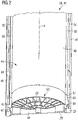
- Figure 2 shows a lower part of the second body 22 of the housing 40.
- An insert 60 is arranged at an end portion of the housing 40.
- an end portion 67 of the insert 60 is arranged at a wall 50 of the housing 40.
- the shape of the cross section of the wall 50 is continued by a wall structure 62 of the insert 60.
- the wall structure 62 is annular, i.e. formed as a sleeve or a shell with an extension along longitudinal axis A.
- the insert 60 comprises also a disc-shaped support structure 64 that has a radial extension being basically perpendicular to the longitudinal axis A of the housing 40.
- the wall structure 62 of the insert 60 forms at least partly a first annular channel 41.
- the first annular channel 41 is also formed by a tubular element 46 that is arranged at the wall 50.
- Cover plates 44 and the wall 50 of the housing 40 form inlet and outlet channels 52, 54 that extend basically along the longitudinal axis A.
- the inlet and outlet channels 52, 54 are connected to the first annular channel 41 at mutual opposite locations.
- the first annular channel 41 is limited along the longitudinal axis A by a partition wall 66 that basically surrounds the perimeter of the wall structure 62.
- the partition wall 66 forms at least partly a second annular channel 42.
- the second annular channel 42 is connected to an internal space 48 of the housing 40 via an opening 68 that is arranged at and/or in the insert 60.
- the insert 60 or its wall structure 62, respectively, forms a seamless inner surface 49.
- a foil element 28 and a retainer 29 can be optimally arranged at the support structure 62 and at the housing 40 or the tubular element 46, respectively.
- the foil is preferably bonded to an outer surface of the retainer, e.g. by diffusion bonding.
- the outer surface of the retainer 29 is arranged at a distance, along the longitudinal axis A, from the outer surface of the support structure 62. Thereby, the bonding line of the foil is formed on a plateau, i.e. elevated, compared to the outer surface of the support structure 62.
- FIG 3 shows an end portion of a housing 40.
- an insert 60 is shown from an inside of the housing 40.
- the housing 40 is formed by a wall 50, wherein inlet and outlet channels 52, 54 are formed by the wall 50 and appropriate cover plates 44.
- the cover plates 44 and the wall 50 form an outer surface 47 of the housing 40.
- the outer surface 47 is continued by a tubular element 46 that surrounds the insert 60.
- the insert 60 comprises a support structure 64 and a wall structure 62, wherein the wall structure 62 and the wall 50 form an inner surface 49 of the housing 40.
- An internal space 48 of the housing 40 is connected to a second annular channel (not visible) via at least one opening 68.
- the tubular element 46 may be an integrated, i.e. in one piece formed, portion of the rest of the housing 40.
- Figure 4 shows an embodiment of an insert 60 that is arranged at the housing 40.
- a tubular element 46 is arranged at the housing 40.
- the tubular element 46 is shown transparent so that a shape of an inlet channel 52 can be seen.
- the outlet or inlet channel 52, 54 is connected to a first annular channel 41 that is formed by the insert 60 and in particular by a wall structure 62 of the insert 60.
- the outlet channel is not visible in Figure 4 since it is being located opposite the inlet channel 52.
- the flow of the medium entering the first annular channel 41, from the inlet channel 52 will be divided into two flows, one directed clockwise towards the outlet channel and the other directed counterclockwise towards the outlet channel. Arrows illustrate this.
- An end portion 67 continues the form and design of a wall 50 of the housing 40.
- the inlet or outlet channel 52, 54 is formed by the wall 50 of the housing 40 and a cover plate 44.
- the cover plate 44 forms together with the wall 50 of the housing 40 an outer surface 47.
- the insert 60 comprises a partition wall 66 that is adapted to form at least partly a second annular channel 42 (see Figure 2 ), wherein a connection from an internal space of the housing 40 to the second annular channel 42 can be realized by a plurality of openings 68.
- the insert 60 comprises a grid- or web-like support structure 64.
- Figure 5a just shows an intersection plane of an embodiment of an electron beam emitter 20 comprising a first body 21 and a second body 22, wherein the second body 22 comprises an electron exit window 26.
- the small arrow indicates a viewing direction for the sectioning shown in Figure 5b .
- Figure 5b shows a filament 24 that is arranged inside the first body 21 of a housing 40.
- Two semicircular pockets are shown that merge to the already known shape of the inlet and outlet channels 52, 54, as for example shown in Figure 4 .
- This allows a basically perpendicular deflection of a (cooling) medium flow from connection ports 56 to the inlet and outlet channels 52, 54 respectively.
- the connection ports 56 are indicated by the dotted lines.
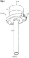
- Figure 6 shows a further embodiment of an electron beam emitter 20 comprising a housing 40, wherein the housing 40 comprises a first body 21 and a second body 22.
- the housing 40 extends along a longitudinal axis A, wherein the second body 22 comprises an electron exit window 26 with a foil element 28 at its end portion.
- a kind of flange wherein the flange comprises two connection ports 56 that are adapted to supply a cooling medium.
- the flange comprises four openings or holes that can be used to arrange the electron beam emitter for example at a movable or rotatable carousel or carrier plate.
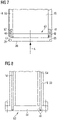
- FIG 7 shows a principle scheme of an arrangement of an insert 60 at a housing 40.
- the housing 40 comprises a wall 50 (without cover plates).
- the insert 60 comprises a wall structure 62 and a support structure 64.
- a first annular channel 42 is formed by the insert 60 and in particular by the wall structure 62 and by a partition wall 66.
- the partition wall 66 forms furthermore a second annular channel 42 that is connected via an opening 68 to an internal space 48 of the housing 40.
- a foil element 28 and a retainer 29 can be easily arranged at the insert 60 and the housing 40 e.g. moving it along the direction of the small arrow that extends along the longitudinal axis A.
- Figure 8 shows a further embodiment of an insert 60 that comprises a support structure 64 and a wall structure 62.
- the arrangement at a housing 40 that comprises inlet and outlet channels 52, 54 is different.
- the housing 40 forms a kind of flange, wherein the insert 60 can be arranged at the flange via appropriate fixing material, e. g, indicated by the dashed lines.
- a foil element and its arrangement are not shown in Figure 8 .
- the electron beam emitter may be connected to a conditioning system as described in the Swedish Patent Application No. SE 1450217-3 filed by the applicant.
- the cooling medium is first used to cool a power supply unit connected to the electron beam emitter.
- the flow direction of the medium is directed from the power supply unit to the electron beam emitter.
- the temperature level of the power supply unit is lower than a temperature level of the electron beam emitter. This means that the medium flow that has already been heated up during cooling of the power supply unit can still be used for cooling the electron beam emitter and in particular its electron exit window.
- the electron exit window is cooled with a medium flow that is warmer than an ambient temperature of the electron exit window. In that way condensation on the electron exit window may be avoided.
- the electron beam emitter 20 can be arranged in an irradiation chamber in a filling machine.
- the filling machine comprises at least one filling station for filling content into the packaging container and at least one station for sealing the opening after filling.
- the electron beam emitter can for example be applied in the application described in the international application No. PCT/EP2013/076870 filed by the applicant.
- a plurality of emitters can be provided on a carousel or the like which is adapted to rotate. The emitters may be arranged in holes in the carousel.
- the packaging containers which are transported for example via a conveyor, reach the carousel and are engaged with one of the (rotating) emitters for interior surface sterilization.
- the interior sterilization takes place.
- a relative movement is created between the packaging container and the electron beam emitter, in particular the packaging containers are lifted to surround the electron beam emitters such that the electron cloud emitted through the electron exit window is inserted into the packaging container and can reach the interior surface thereof.
- the packaging container is removed from the emitter or from the carousel, respectively.
- the packaging container is then subsequently transported through an electron cloud provided in a gap between two emitters for outside surface sterilization.
Landscapes
- Health & Medical Sciences (AREA)
- General Health & Medical Sciences (AREA)
- Engineering & Computer Science (AREA)
- Veterinary Medicine (AREA)
- Animal Behavior & Ethology (AREA)
- Public Health (AREA)
- Life Sciences & Earth Sciences (AREA)
- Epidemiology (AREA)
- Mechanical Engineering (AREA)
- Manufacturing & Machinery (AREA)
- Physics & Mathematics (AREA)
- General Engineering & Computer Science (AREA)
- High Energy & Nuclear Physics (AREA)
- Toxicology (AREA)
- Apparatus For Disinfection Or Sterilisation (AREA)
Claims (10)
- Émetteur de faisceau d'électrons (20), en particulier pour la stérilisation de matériau d'emballage,comprenant un boîtier (40), une fenêtre de sortie d'électrons (26) et une pièce rapportée (60),dans lequel le boîtier (40) comprend un premier canal annulaire (41) destiné à guider un milieu, etdans lequel le premier canal annulaire (41) entoure au moins partiellement la pièce rapportée (60) et est adapté pour fournir le milieu,caractérisé en ce quele premier canal annulaire (41) est au moins partiellement formé par la pièce rapportée (60),dans lequel la pièce rapportée (60) est adaptée pour former une partie de la fenêtre de sortie d'électrons (26),dans lequel le boîtier (40) comprend au moins un canal d'entrée (52) et au moins un canal de sortie (54), et dans lequel les canaux de sortie et d'entrée (52, 54) sont raccordés au et en raccordement fluidique avec le premier canal annulaire (41), et qui sont adaptés pour fournir le milieu au premier canal annulaire (41),dans lequel le boîtier (40) comprend au moins un orifice de raccordement (56) pour le canal d'entrée (52) et au moins un orifice de raccordement (56) pour le canal de sortie (54), lesdits orifices de raccordement étant raccordés à une source de milieu, etdans lequel la pièce rapportée (60) comprend une paroi de séparation (66),dans lequel la paroi de séparation (66) forme au moins partiellement un deuxième canal annulaire (42),
etdans lequel la pièce rapportée (60) comprend au moins une ouverture (68), etdans lequel l'au moins une ouverture (68) est adaptée pour fournir un raccordement entre un espace interne (48) du boîtier (40) et le deuxième canal annulaire (42). - Émetteur de faisceau d'électrons (20) selon la revendication 1,dans lequel le boîtier (40) comprend un premier corps (21) et un deuxième corps (22),dans lequel le premier corps (21) comprend un boîtier de cathode et un filament (24), etdans lequel la pièce rapportée (60) est disposée au niveau du deuxième corps (22).
- Émetteur de faisceau d'électrons (20) selon l'une quelconque des revendications précédentes,dans lequel la pièce rapportée (60) comprend une structure de support (64) et une structure de paroi (62),la structure de paroi (62) formant au moins partiellement le premier canal annulaire (41).
- Émetteur de faisceau d'électrons (20) selon l'une quelconque des revendications précédentes, dans lequel la pièce rapportée (60) comprend une structure de support (64), l'émetteur de faisceau d'électrons comprenant un élément en feuille (28), et l'élément en feuille (28) étant disposé pour être supporté par la structure de support.
- Émetteur de faisceau d'électrons (20) selon l'une quelconque des revendications précédentes,dans lequel l'élément en feuille (28) est disposé au niveau d'un dispositif de retenue (29), etdans lequel le dispositif de retenue (29) est disposé au niveau du boîtier (40).
- Émetteur de faisceau d'électrons (20) selon l'une quelconque des revendications précédentes,dans lequel le boîtier (40) comprend au moins une plaque de recouvrement (44),l'au moins une plaque de recouvrement (44) étant adaptée pour former une surface externe (47) du boîtier (40) et pour former au moins partiellement le canal d'entrée et de sortie.
- Émetteur de faisceau d'électrons (20) selon l'une quelconque des revendications précédentes,dans lequel le boîtier (40) comprend un élément tubulaire (46),l'élément tubulaire (46) et la pièce rapportée (60) formant le premier canal annulaire (41).
- Émetteur de faisceau d'électrons (20) selon l'une quelconque des revendications précédentes, dans lequel les canaux d'entrée et de sortie (52, 54) débouchent à des positions mutuellement opposées dans le premier canal annulaire (41) de telle sorte que le milieu, à son entrée dans le premier canal annulaire depuis le canal d'entrée (52), sera divisé en deux écoulements, l'un prenant une direction horaire et l'autre une direction antihoraire vers le canal de sortie (54).
- Émetteur de faisceau d'électrons (20) selon l'une quelconque des revendications précédentes, dans lequel le milieu est l'eau ou un autre réfrigérant liquide.
- Dispositif de stérilisation, en particulier pour matériau d'emballage,comprenant une unité d'alimentation électrique et au moins un émetteur de faisceau d'électrons (20) selon la revendication 1,dans lequel l'émetteur de faisceau d'électrons (20) comprend un boîtier (40) et une pièce rapportée (60),dans lequel le boîtier (40) comprend un premier canal annulaire (41), etdans lequel le premier canal annulaire (41) entoure la pièce rapportée (60),le premier canal annulaire (41) étant adapté pour fournir un milieu,caractérisé en ce quele premier canal annulaire (41) est au moins partiellement formé par la pièce rapportée (60),dans lequel la pièce rapportée (60) est adaptée pour former une partie d'une fenêtre de sortie d'électrons (26), et dans lequel le boîtier (40) comprend au moins un canal d'entrée (52) et au moins un canal de sortie (54), le canal de sortie et d'entrée (52, 54) étant raccordé au premier canal annulaire (41) .
Applications Claiming Priority (2)
| Application Number | Priority Date | Filing Date | Title |
|---|---|---|---|
| SE1450334 | 2014-03-24 | ||
| PCT/EP2015/054814 WO2015144425A1 (fr) | 2014-03-24 | 2015-03-09 | Émetteur de faisceau d'électrons |
Publications (3)
| Publication Number | Publication Date |
|---|---|
| EP3122385A1 EP3122385A1 (fr) | 2017-02-01 |
| EP3122385B1 EP3122385B1 (fr) | 2018-11-14 |
| EP3122385B2 true EP3122385B2 (fr) | 2022-06-15 |
Family
ID=52824215
Family Applications (1)
| Application Number | Title | Priority Date | Filing Date |
|---|---|---|---|
| EP15715685.2A Active EP3122385B2 (fr) | 2014-03-24 | 2015-03-09 | Émetteur de faisceau d'électrons |
Country Status (9)
| Country | Link |
|---|---|
| US (1) | US20180170600A1 (fr) |
| EP (1) | EP3122385B2 (fr) |
| JP (1) | JP6607863B2 (fr) |
| CN (1) | CN106102782B (fr) |
| BR (1) | BR112016021845B1 (fr) |
| CA (1) | CA2941516C (fr) |
| MX (1) | MX361641B (fr) |
| RU (1) | RU2688941C2 (fr) |
| WO (1) | WO2015144425A1 (fr) |
Families Citing this family (6)
| Publication number | Priority date | Publication date | Assignee | Title |
|---|---|---|---|---|
| MX361641B (es) | 2014-03-24 | 2018-12-13 | Tetra Laval Holdings & Finance | Emisor de haz de electrones. |
| JP2018019805A (ja) * | 2016-08-02 | 2018-02-08 | 日立造船株式会社 | 内面電子線照射装置およびこれを具備する電子線滅菌設備 |
| FR3061403B1 (fr) * | 2016-12-22 | 2023-02-17 | P M B | Systeme de ciblerie a gaz pour production de radio-isotopes |
| DE112018006804B4 (de) * | 2018-02-07 | 2024-05-29 | Hitachi High-Tech Canada, Inc. | Reinigungsvorrichtung |
| US20200108165A1 (en) * | 2018-10-05 | 2020-04-09 | Carlos Manuel Poventud-Estrada | Handheld and rechargeable battery operated device invented to eliminate the bad odor produced by human flatulence and feces by ignition. |
| CN114906420A (zh) * | 2021-02-07 | 2022-08-16 | 湖州超群电子科技有限公司 | 一种用于开口容器的新型电子束杀菌消毒系统及其方法 |
Citations (2)
| Publication number | Priority date | Publication date | Assignee | Title |
|---|---|---|---|---|
| JP2003307598A (ja) † | 2002-04-15 | 2003-10-31 | Iwasaki Electric Co Ltd | 電子ビーム放出管 |
| EP2991078A1 (fr) † | 2013-04-26 | 2016-03-02 | Hitachi Zosen Corporation | Appareil d'irradiation de faisceau d'électrons |
Family Cites Families (19)
| Publication number | Priority date | Publication date | Assignee | Title |
|---|---|---|---|---|
| GB277347A (en) | 1926-09-07 | 1928-12-07 | Mueller C H F Ag | Improvements in or relating to cathode ray tubes |
| JPS6138500A (ja) | 1984-07-30 | 1986-02-24 | 日新ハイボルテ−ジ株式会社 | 照射窓 |
| JPH0687900U (ja) | 1993-06-07 | 1994-12-22 | 日新ハイボルテージ株式会社 | 電子線照射装置 |
| JPH0929500A (ja) | 1995-07-18 | 1997-02-04 | Amada Co Ltd | ラム昇降駆動装置 |
| JPH0999042A (ja) * | 1995-10-02 | 1997-04-15 | Material Eng Tech Lab Inc | 薬剤の滅菌方法 |
| JPH09292500A (ja) | 1996-04-25 | 1997-11-11 | Nissin High Voltage Co Ltd | 電子線照射装置の窓箔冷却構造 |
| JP2000346998A (ja) | 1999-06-07 | 2000-12-15 | Ebara Corp | 電子線照射装置 |
| ATE496387T1 (de) * | 1999-07-09 | 2011-02-15 | Advanced Electron Beams Inc A Delaware Corp | Elektronenstrahlbeschleuniger |
| JP2001221899A (ja) | 2000-02-07 | 2001-08-17 | Ebara Corp | 電子線照射装置 |
| JP2001311800A (ja) | 2000-04-28 | 2001-11-09 | Ebara Corp | 電子線照射用ターゲット |
| FR2861215B1 (fr) * | 2003-10-20 | 2006-05-19 | Calhene | Canon a electrons a anode focalisante, formant une fenetre de ce canon, application a l'irradiation et a la sterilisation |
| EP1982920A1 (fr) * | 2007-04-19 | 2008-10-22 | Krones AG | Dispositif de stérilisation de récipients |
| DE102008025868A1 (de) * | 2008-05-30 | 2009-12-03 | Krones Ag | Vorrichtung zum Sterilisieren von Behältnissen mittels Ladungsträgern |
| JP5645562B2 (ja) * | 2010-09-10 | 2014-12-24 | 三菱重工業株式会社 | 電子線殺菌装置 |
| DE102012106555A1 (de) | 2012-07-19 | 2014-05-22 | Krones Ag | Verfahren und Vorrichtung zum Sterilisieren von Behältnissen mit Kühlluftentnahme aus dem Sterilraum |
| DE202012103519U1 (de) | 2012-09-14 | 2012-10-04 | Krones Ag | Vorrichtung zum Sterilisieren von Behältnissen mit Aufbereitung für Kühlmedium |
| DE102012112368A1 (de) * | 2012-12-17 | 2014-06-18 | Krones Ag | Vorrichtung und Verfahren zum Rinsen |
| DE102013109584A1 (de) * | 2013-09-03 | 2015-03-05 | Krones Ag | Verfahren und Vorrichtung zum Sterilisieren von Behältnissen mit Reinigung eines Strahlaustrittsfensters |
| MX361641B (es) | 2014-03-24 | 2018-12-13 | Tetra Laval Holdings & Finance | Emisor de haz de electrones. |
-
2015
- 2015-03-09 MX MX2016011579A patent/MX361641B/es active IP Right Grant
- 2015-03-09 RU RU2016137884A patent/RU2688941C2/ru active
- 2015-03-09 JP JP2016558645A patent/JP6607863B2/ja active Active
- 2015-03-09 BR BR112016021845-0A patent/BR112016021845B1/pt not_active IP Right Cessation
- 2015-03-09 WO PCT/EP2015/054814 patent/WO2015144425A1/fr active Application Filing
- 2015-03-09 CN CN201580012671.2A patent/CN106102782B/zh active Active
- 2015-03-09 US US15/128,383 patent/US20180170600A1/en not_active Abandoned
- 2015-03-09 CA CA2941516A patent/CA2941516C/fr not_active Expired - Fee Related
- 2015-03-09 EP EP15715685.2A patent/EP3122385B2/fr active Active
Patent Citations (2)
| Publication number | Priority date | Publication date | Assignee | Title |
|---|---|---|---|---|
| JP2003307598A (ja) † | 2002-04-15 | 2003-10-31 | Iwasaki Electric Co Ltd | 電子ビーム放出管 |
| EP2991078A1 (fr) † | 2013-04-26 | 2016-03-02 | Hitachi Zosen Corporation | Appareil d'irradiation de faisceau d'électrons |
Also Published As
| Publication number | Publication date |
|---|---|
| MX2016011579A (es) | 2016-12-07 |
| CA2941516C (fr) | 2019-04-16 |
| EP3122385A1 (fr) | 2017-02-01 |
| EP3122385B1 (fr) | 2018-11-14 |
| WO2015144425A1 (fr) | 2015-10-01 |
| CN106102782A (zh) | 2016-11-09 |
| RU2016137884A (ru) | 2018-04-24 |
| CN106102782B (zh) | 2019-12-03 |
| JP2017513570A (ja) | 2017-06-01 |
| MX361641B (es) | 2018-12-13 |
| RU2688941C2 (ru) | 2019-05-23 |
| US20180170600A1 (en) | 2018-06-21 |
| BR112016021845B1 (pt) | 2020-11-17 |
| JP6607863B2 (ja) | 2019-11-20 |
| RU2016137884A3 (fr) | 2018-11-30 |
| CA2941516A1 (fr) | 2015-10-01 |
Similar Documents
| Publication | Publication Date | Title |
|---|---|---|
| EP3122385B2 (fr) | Émetteur de faisceau d'électrons | |
| ES2298781T3 (es) | Dispositivo y metodo de esterilizacion. | |
| CN101310773B (zh) | 容器消毒装置、系统和方法 | |
| KR100454996B1 (ko) | 제품 살균 패키지, 제품 살균 카트리지 하우징, 및 제품살균용 가스 또는 증기 방출 방법 | |
| JP6007279B2 (ja) | 電荷担体による容器殺菌装置 | |
| ES2607108T3 (es) | Tambor giratorio con dispositivo de calefacción para liofilizador | |
| EP2935022B1 (fr) | Dispositif et procédé pour stériliser des récipients d'emballage par faisceau d'électrons | |
| AR080706A1 (es) | Dispositivos, sistemas y metodos para reciclar plasticos | |
| CA3036345C (fr) | Dispositif et procede d'irradiation ultraviolette | |
| JP2012221864A5 (fr) | ||
| CN105939735B (zh) | 用于包装容器的灭菌的装置和方法 | |
| CN106029112B (zh) | 灭菌装置和电子束发射器 | |
| ES2479716T3 (es) | Embalaje para el transporte y/o almacenamiento de materiales radiactivos, que comprende medios de conducción térmica mejorados | |
| JP6306181B2 (ja) | 高出力x線管ハウジング | |
| ES2688754T3 (es) | Método y dispositivo para generar vapor de agua y peróxido de hidrógeno gaseoso | |
| JP2016095916A5 (fr) | ||
| CN106029110B (zh) | 用于给包装容器杀菌的杀菌机器和方法 | |
| CN106029111B (zh) | 电源 | |
| EP2746174B1 (fr) | Dispositif et procédé pour stériliser des récipients d'emballage par faisceau d'électrons |
Legal Events
| Date | Code | Title | Description |
|---|---|---|---|
| STAA | Information on the status of an ep patent application or granted ep patent |
Free format text: STATUS: THE INTERNATIONAL PUBLICATION HAS BEEN MADE |
|
| PUAI | Public reference made under article 153(3) epc to a published international application that has entered the european phase |
Free format text: ORIGINAL CODE: 0009012 |
|
| STAA | Information on the status of an ep patent application or granted ep patent |
Free format text: STATUS: REQUEST FOR EXAMINATION WAS MADE |
|
| 17P | Request for examination filed |
Effective date: 20161024 |
|
| AK | Designated contracting states |
Kind code of ref document: A1 Designated state(s): AL AT BE BG CH CY CZ DE DK EE ES FI FR GB GR HR HU IE IS IT LI LT LU LV MC MK MT NL NO PL PT RO RS SE SI SK SM TR |
|
| AX | Request for extension of the european patent |
Extension state: BA ME |
|
| DAV | Request for validation of the european patent (deleted) | ||
| DAX | Request for extension of the european patent (deleted) | ||
| GRAP | Despatch of communication of intention to grant a patent |
Free format text: ORIGINAL CODE: EPIDOSNIGR1 |
|
| STAA | Information on the status of an ep patent application or granted ep patent |
Free format text: STATUS: GRANT OF PATENT IS INTENDED |
|
| INTG | Intention to grant announced |
Effective date: 20180530 |
|
| GRAS | Grant fee paid |
Free format text: ORIGINAL CODE: EPIDOSNIGR3 |
|
| GRAA | (expected) grant |
Free format text: ORIGINAL CODE: 0009210 |
|
| STAA | Information on the status of an ep patent application or granted ep patent |
Free format text: STATUS: THE PATENT HAS BEEN GRANTED |
|
| AK | Designated contracting states |
Kind code of ref document: B1 Designated state(s): AL AT BE BG CH CY CZ DE DK EE ES FI FR GB GR HR HU IE IS IT LI LT LU LV MC MK MT NL NO PL PT RO RS SE SI SK SM TR |
|
| REG | Reference to a national code |
Ref country code: CH Ref legal event code: EP Ref country code: AT Ref legal event code: REF Ref document number: 1064035 Country of ref document: AT Kind code of ref document: T Effective date: 20181115 |
|
| REG | Reference to a national code |
Ref country code: DE Ref legal event code: R096 Ref document number: 602015019830 Country of ref document: DE |
|
| REG | Reference to a national code |
Ref country code: IE Ref legal event code: FG4D |
|
| REG | Reference to a national code |
Ref country code: NL Ref legal event code: MP Effective date: 20181114 |
|
| REG | Reference to a national code |
Ref country code: LT Ref legal event code: MG4D |
|
| REG | Reference to a national code |
Ref country code: AT Ref legal event code: MK05 Ref document number: 1064035 Country of ref document: AT Kind code of ref document: T Effective date: 20181114 |
|
| PG25 | Lapsed in a contracting state [announced via postgrant information from national office to epo] |
Ref country code: BG Free format text: LAPSE BECAUSE OF FAILURE TO SUBMIT A TRANSLATION OF THE DESCRIPTION OR TO PAY THE FEE WITHIN THE PRESCRIBED TIME-LIMIT Effective date: 20190214 Ref country code: NO Free format text: LAPSE BECAUSE OF FAILURE TO SUBMIT A TRANSLATION OF THE DESCRIPTION OR TO PAY THE FEE WITHIN THE PRESCRIBED TIME-LIMIT Effective date: 20190214 Ref country code: HR Free format text: LAPSE BECAUSE OF FAILURE TO SUBMIT A TRANSLATION OF THE DESCRIPTION OR TO PAY THE FEE WITHIN THE PRESCRIBED TIME-LIMIT Effective date: 20181114 Ref country code: LT Free format text: LAPSE BECAUSE OF FAILURE TO SUBMIT A TRANSLATION OF THE DESCRIPTION OR TO PAY THE FEE WITHIN THE PRESCRIBED TIME-LIMIT Effective date: 20181114 Ref country code: IS Free format text: LAPSE BECAUSE OF FAILURE TO SUBMIT A TRANSLATION OF THE DESCRIPTION OR TO PAY THE FEE WITHIN THE PRESCRIBED TIME-LIMIT Effective date: 20190314 Ref country code: ES Free format text: LAPSE BECAUSE OF FAILURE TO SUBMIT A TRANSLATION OF THE DESCRIPTION OR TO PAY THE FEE WITHIN THE PRESCRIBED TIME-LIMIT Effective date: 20181114 Ref country code: AT Free format text: LAPSE BECAUSE OF FAILURE TO SUBMIT A TRANSLATION OF THE DESCRIPTION OR TO PAY THE FEE WITHIN THE PRESCRIBED TIME-LIMIT Effective date: 20181114 Ref country code: LV Free format text: LAPSE BECAUSE OF FAILURE TO SUBMIT A TRANSLATION OF THE DESCRIPTION OR TO PAY THE FEE WITHIN THE PRESCRIBED TIME-LIMIT Effective date: 20181114 Ref country code: FI Free format text: LAPSE BECAUSE OF FAILURE TO SUBMIT A TRANSLATION OF THE DESCRIPTION OR TO PAY THE FEE WITHIN THE PRESCRIBED TIME-LIMIT Effective date: 20181114 |
|
| PG25 | Lapsed in a contracting state [announced via postgrant information from national office to epo] |
Ref country code: AL Free format text: LAPSE BECAUSE OF FAILURE TO SUBMIT A TRANSLATION OF THE DESCRIPTION OR TO PAY THE FEE WITHIN THE PRESCRIBED TIME-LIMIT Effective date: 20181114 Ref country code: RS Free format text: LAPSE BECAUSE OF FAILURE TO SUBMIT A TRANSLATION OF THE DESCRIPTION OR TO PAY THE FEE WITHIN THE PRESCRIBED TIME-LIMIT Effective date: 20181114 Ref country code: SE Free format text: LAPSE BECAUSE OF FAILURE TO SUBMIT A TRANSLATION OF THE DESCRIPTION OR TO PAY THE FEE WITHIN THE PRESCRIBED TIME-LIMIT Effective date: 20181114 Ref country code: NL Free format text: LAPSE BECAUSE OF FAILURE TO SUBMIT A TRANSLATION OF THE DESCRIPTION OR TO PAY THE FEE WITHIN THE PRESCRIBED TIME-LIMIT Effective date: 20181114 Ref country code: GR Free format text: LAPSE BECAUSE OF FAILURE TO SUBMIT A TRANSLATION OF THE DESCRIPTION OR TO PAY THE FEE WITHIN THE PRESCRIBED TIME-LIMIT Effective date: 20190215 Ref country code: PT Free format text: LAPSE BECAUSE OF FAILURE TO SUBMIT A TRANSLATION OF THE DESCRIPTION OR TO PAY THE FEE WITHIN THE PRESCRIBED TIME-LIMIT Effective date: 20190314 |
|
| PG25 | Lapsed in a contracting state [announced via postgrant information from national office to epo] |
Ref country code: PL Free format text: LAPSE BECAUSE OF FAILURE TO SUBMIT A TRANSLATION OF THE DESCRIPTION OR TO PAY THE FEE WITHIN THE PRESCRIBED TIME-LIMIT Effective date: 20181114 Ref country code: DK Free format text: LAPSE BECAUSE OF FAILURE TO SUBMIT A TRANSLATION OF THE DESCRIPTION OR TO PAY THE FEE WITHIN THE PRESCRIBED TIME-LIMIT Effective date: 20181114 Ref country code: CZ Free format text: LAPSE BECAUSE OF FAILURE TO SUBMIT A TRANSLATION OF THE DESCRIPTION OR TO PAY THE FEE WITHIN THE PRESCRIBED TIME-LIMIT Effective date: 20181114 |
|
| REG | Reference to a national code |
Ref country code: DE Ref legal event code: R026 Ref document number: 602015019830 Country of ref document: DE |
|
| PLBI | Opposition filed |
Free format text: ORIGINAL CODE: 0009260 |
|
| PG25 | Lapsed in a contracting state [announced via postgrant information from national office to epo] |
Ref country code: SK Free format text: LAPSE BECAUSE OF FAILURE TO SUBMIT A TRANSLATION OF THE DESCRIPTION OR TO PAY THE FEE WITHIN THE PRESCRIBED TIME-LIMIT Effective date: 20181114 Ref country code: RO Free format text: LAPSE BECAUSE OF FAILURE TO SUBMIT A TRANSLATION OF THE DESCRIPTION OR TO PAY THE FEE WITHIN THE PRESCRIBED TIME-LIMIT Effective date: 20181114 Ref country code: EE Free format text: LAPSE BECAUSE OF FAILURE TO SUBMIT A TRANSLATION OF THE DESCRIPTION OR TO PAY THE FEE WITHIN THE PRESCRIBED TIME-LIMIT Effective date: 20181114 Ref country code: SM Free format text: LAPSE BECAUSE OF FAILURE TO SUBMIT A TRANSLATION OF THE DESCRIPTION OR TO PAY THE FEE WITHIN THE PRESCRIBED TIME-LIMIT Effective date: 20181114 |
|
| 26 | Opposition filed |
Opponent name: STRAWMAN LIMITED Effective date: 20190813 |
|
| PLAX | Notice of opposition and request to file observation + time limit sent |
Free format text: ORIGINAL CODE: EPIDOSNOBS2 |
|
| PG25 | Lapsed in a contracting state [announced via postgrant information from national office to epo] |
Ref country code: SI Free format text: LAPSE BECAUSE OF FAILURE TO SUBMIT A TRANSLATION OF THE DESCRIPTION OR TO PAY THE FEE WITHIN THE PRESCRIBED TIME-LIMIT Effective date: 20181114 Ref country code: MC Free format text: LAPSE BECAUSE OF FAILURE TO SUBMIT A TRANSLATION OF THE DESCRIPTION OR TO PAY THE FEE WITHIN THE PRESCRIBED TIME-LIMIT Effective date: 20181114 |
|
| GBPC | Gb: european patent ceased through non-payment of renewal fee |
Effective date: 20190309 |
|
| PG25 | Lapsed in a contracting state [announced via postgrant information from national office to epo] |
Ref country code: LU Free format text: LAPSE BECAUSE OF NON-PAYMENT OF DUE FEES Effective date: 20190309 |
|
| REG | Reference to a national code |
Ref country code: BE Ref legal event code: MM Effective date: 20190331 |
|
| PG25 | Lapsed in a contracting state [announced via postgrant information from national office to epo] |
Ref country code: GB Free format text: LAPSE BECAUSE OF NON-PAYMENT OF DUE FEES Effective date: 20190309 Ref country code: IE Free format text: LAPSE BECAUSE OF NON-PAYMENT OF DUE FEES Effective date: 20190309 |
|
| PLBB | Reply of patent proprietor to notice(s) of opposition received |
Free format text: ORIGINAL CODE: EPIDOSNOBS3 |
|
| PG25 | Lapsed in a contracting state [announced via postgrant information from national office to epo] |
Ref country code: BE Free format text: LAPSE BECAUSE OF NON-PAYMENT OF DUE FEES Effective date: 20190331 |
|
| PG25 | Lapsed in a contracting state [announced via postgrant information from national office to epo] |
Ref country code: TR Free format text: LAPSE BECAUSE OF FAILURE TO SUBMIT A TRANSLATION OF THE DESCRIPTION OR TO PAY THE FEE WITHIN THE PRESCRIBED TIME-LIMIT Effective date: 20181114 |
|
| PLAY | Examination report in opposition despatched + time limit |
Free format text: ORIGINAL CODE: EPIDOSNORE2 |
|
| PG25 | Lapsed in a contracting state [announced via postgrant information from national office to epo] |
Ref country code: MT Free format text: LAPSE BECAUSE OF NON-PAYMENT OF DUE FEES Effective date: 20190309 |
|
| PLBC | Reply to examination report in opposition received |
Free format text: ORIGINAL CODE: EPIDOSNORE3 |
|
| PLAY | Examination report in opposition despatched + time limit |
Free format text: ORIGINAL CODE: EPIDOSNORE2 |
|
| PLBC | Reply to examination report in opposition received |
Free format text: ORIGINAL CODE: EPIDOSNORE3 |
|
| PGFP | Annual fee paid to national office [announced via postgrant information from national office to epo] |
Ref country code: FR Payment date: 20210326 Year of fee payment: 7 Ref country code: CH Payment date: 20210322 Year of fee payment: 7 |
|
| PG25 | Lapsed in a contracting state [announced via postgrant information from national office to epo] |
Ref country code: CY Free format text: LAPSE BECAUSE OF FAILURE TO SUBMIT A TRANSLATION OF THE DESCRIPTION OR TO PAY THE FEE WITHIN THE PRESCRIBED TIME-LIMIT Effective date: 20181114 |
|
| PG25 | Lapsed in a contracting state [announced via postgrant information from national office to epo] |
Ref country code: HU Free format text: LAPSE BECAUSE OF FAILURE TO SUBMIT A TRANSLATION OF THE DESCRIPTION OR TO PAY THE FEE WITHIN THE PRESCRIBED TIME-LIMIT; INVALID AB INITIO Effective date: 20150309 |
|
| PUAH | Patent maintained in amended form |
Free format text: ORIGINAL CODE: 0009272 |
|
| STAA | Information on the status of an ep patent application or granted ep patent |
Free format text: STATUS: PATENT MAINTAINED AS AMENDED |
|
| 27A | Patent maintained in amended form |
Effective date: 20220615 |
|
| AK | Designated contracting states |
Kind code of ref document: B2 Designated state(s): AL AT BE BG CH CY CZ DE DK EE ES FI FR GB GR HR HU IE IS IT LI LT LU LV MC MK MT NL NO PL PT RO RS SE SI SK SM TR |
|
| REG | Reference to a national code |
Ref country code: DE Ref legal event code: R102 Ref document number: 602015019830 Country of ref document: DE |
|
| PG25 | Lapsed in a contracting state [announced via postgrant information from national office to epo] |
Ref country code: MK Free format text: LAPSE BECAUSE OF FAILURE TO SUBMIT A TRANSLATION OF THE DESCRIPTION OR TO PAY THE FEE WITHIN THE PRESCRIBED TIME-LIMIT Effective date: 20181114 |
|
| REG | Reference to a national code |
Ref country code: CH Ref legal event code: PL |
|
| PG25 | Lapsed in a contracting state [announced via postgrant information from national office to epo] |
Ref country code: LI Free format text: LAPSE BECAUSE OF NON-PAYMENT OF DUE FEES Effective date: 20220331 Ref country code: FR Free format text: LAPSE BECAUSE OF NON-PAYMENT OF DUE FEES Effective date: 20220331 Ref country code: CH Free format text: LAPSE BECAUSE OF NON-PAYMENT OF DUE FEES Effective date: 20220331 |
|
| PGFP | Annual fee paid to national office [announced via postgrant information from national office to epo] |
Ref country code: IT Payment date: 20230321 Year of fee payment: 9 |
|
| P01 | Opt-out of the competence of the unified patent court (upc) registered |
Effective date: 20230426 |
|
| PGFP | Annual fee paid to national office [announced via postgrant information from national office to epo] |
Ref country code: DE Payment date: 20240328 Year of fee payment: 10 |