EP3115863A2 - Steuerelement - Google Patents
Steuerelement Download PDFInfo
- Publication number
- EP3115863A2 EP3115863A2 EP16175706.7A EP16175706A EP3115863A2 EP 3115863 A2 EP3115863 A2 EP 3115863A2 EP 16175706 A EP16175706 A EP 16175706A EP 3115863 A2 EP3115863 A2 EP 3115863A2
- Authority
- EP
- European Patent Office
- Prior art keywords
- front surface
- proportional
- joystick
- control element
- element according
- Prior art date
- Legal status (The legal status is an assumption and is not a legal conclusion. Google has not performed a legal analysis and makes no representation as to the accuracy of the status listed.)
- Granted
Links
Images







Classifications
-
- G—PHYSICS
- G05—CONTROLLING; REGULATING
- G05G—CONTROL DEVICES OR SYSTEMS INSOFAR AS CHARACTERISED BY MECHANICAL FEATURES ONLY
- G05G9/00—Manually-actuated control mechanisms provided with one single controlling member co-operating with two or more controlled members, e.g. selectively, simultaneously
- G05G9/02—Manually-actuated control mechanisms provided with one single controlling member co-operating with two or more controlled members, e.g. selectively, simultaneously the controlling member being movable in different independent ways, movement in each individual way actuating one controlled member only
- G05G9/04—Manually-actuated control mechanisms provided with one single controlling member co-operating with two or more controlled members, e.g. selectively, simultaneously the controlling member being movable in different independent ways, movement in each individual way actuating one controlled member only in which movement in two or more ways can occur simultaneously
- G05G9/047—Manually-actuated control mechanisms provided with one single controlling member co-operating with two or more controlled members, e.g. selectively, simultaneously the controlling member being movable in different independent ways, movement in each individual way actuating one controlled member only in which movement in two or more ways can occur simultaneously the controlling member being movable by hand about orthogonal axes, e.g. joysticks
- G05G9/04785—Manually-actuated control mechanisms provided with one single controlling member co-operating with two or more controlled members, e.g. selectively, simultaneously the controlling member being movable in different independent ways, movement in each individual way actuating one controlled member only in which movement in two or more ways can occur simultaneously the controlling member being movable by hand about orthogonal axes, e.g. joysticks the controlling member being the operating part of a switch arrangement
- G05G9/04788—Manually-actuated control mechanisms provided with one single controlling member co-operating with two or more controlled members, e.g. selectively, simultaneously the controlling member being movable in different independent ways, movement in each individual way actuating one controlled member only in which movement in two or more ways can occur simultaneously the controlling member being movable by hand about orthogonal axes, e.g. joysticks the controlling member being the operating part of a switch arrangement comprising additional control elements
-
- G—PHYSICS
- G05—CONTROLLING; REGULATING
- G05G—CONTROL DEVICES OR SYSTEMS INSOFAR AS CHARACTERISED BY MECHANICAL FEATURES ONLY
- G05G9/00—Manually-actuated control mechanisms provided with one single controlling member co-operating with two or more controlled members, e.g. selectively, simultaneously
- G05G9/02—Manually-actuated control mechanisms provided with one single controlling member co-operating with two or more controlled members, e.g. selectively, simultaneously the controlling member being movable in different independent ways, movement in each individual way actuating one controlled member only
- G05G9/04—Manually-actuated control mechanisms provided with one single controlling member co-operating with two or more controlled members, e.g. selectively, simultaneously the controlling member being movable in different independent ways, movement in each individual way actuating one controlled member only in which movement in two or more ways can occur simultaneously
- G05G9/047—Manually-actuated control mechanisms provided with one single controlling member co-operating with two or more controlled members, e.g. selectively, simultaneously the controlling member being movable in different independent ways, movement in each individual way actuating one controlled member only in which movement in two or more ways can occur simultaneously the controlling member being movable by hand about orthogonal axes, e.g. joysticks
-
- G—PHYSICS
- G05—CONTROLLING; REGULATING
- G05G—CONTROL DEVICES OR SYSTEMS INSOFAR AS CHARACTERISED BY MECHANICAL FEATURES ONLY
- G05G1/00—Controlling members, e.g. knobs or handles; Assemblies or arrangements thereof; Indicating position of controlling members
- G05G1/58—Rests or guides for relevant parts of the operator's body
-
- G—PHYSICS
- G05—CONTROLLING; REGULATING
- G05G—CONTROL DEVICES OR SYSTEMS INSOFAR AS CHARACTERISED BY MECHANICAL FEATURES ONLY
- G05G9/00—Manually-actuated control mechanisms provided with one single controlling member co-operating with two or more controlled members, e.g. selectively, simultaneously
- G05G9/02—Manually-actuated control mechanisms provided with one single controlling member co-operating with two or more controlled members, e.g. selectively, simultaneously the controlling member being movable in different independent ways, movement in each individual way actuating one controlled member only
- G05G9/04—Manually-actuated control mechanisms provided with one single controlling member co-operating with two or more controlled members, e.g. selectively, simultaneously the controlling member being movable in different independent ways, movement in each individual way actuating one controlled member only in which movement in two or more ways can occur simultaneously
- G05G9/047—Manually-actuated control mechanisms provided with one single controlling member co-operating with two or more controlled members, e.g. selectively, simultaneously the controlling member being movable in different independent ways, movement in each individual way actuating one controlled member only in which movement in two or more ways can occur simultaneously the controlling member being movable by hand about orthogonal axes, e.g. joysticks
- G05G2009/04774—Manually-actuated control mechanisms provided with one single controlling member co-operating with two or more controlled members, e.g. selectively, simultaneously the controlling member being movable in different independent ways, movement in each individual way actuating one controlled member only in which movement in two or more ways can occur simultaneously the controlling member being movable by hand about orthogonal axes, e.g. joysticks with additional switches or sensors on the handle
Definitions
- the invention relates to a control with a joystick, as is often used to control the movements of a work machine, in particular a self-propelled work machine.
- control element The basic function of such a control element consists first in the pivoting of his joystick by two mutually angled horizontal axes at the lower end of the joystick so that it can be pushed forward, pulled backwards and also pressed to the left and to the right side.
- Such a joystick is usually held by the operator in the fist, so that either the thumb surrounds the joystick in the upper area or he is on the front of the joystick, while the remaining four fingers surround the joystick and lie on the back.
- either digital actuators such as push buttons or proportional actuators such as slides are arranged on the front and / or on the back, positioned so that it from one of the on respective front or back resting fingers can be operated without the fist altogether let go of the joystick.
- the switching requires either an additional actuator, but in any case a thinking of the operator, on which function the respective actuator is currently set.
- the object of the invention is achieved in that on the first actuator in the form of a joystick beyond - both on the front and on the back of the joystick and possibly also on one of the side surfaces - more particular proportional actuators are arranged, preferably in the region of the head and / or in the transition area between the head and the hands of the joystick.
- the number of physically present proportional actuators is sufficiently large, so that the individual actuator no longer needs to be assigned with different functions and switchable, thereby spared the operator to know or get displayed on what function the proportional actuator is currently set.
- the front surface of the joystick curved, where it extends at its lower end approximately in the vertical direction - the perpendicular to the flat bottom or top of the base body, and at the same time the direction of the lower part of the shaft - and assumes in its upper end region a frontal angle to the vertical, which is between 45 ° and 75 ° , preferably between 53 ° and 65 ° .
- the center of the middle extending between the two side surfaces on the front surfaces also extends arcuately curved, at its lower end approximately in the direction of the vertical, and runs from there curved upwards to the left, so that they at their upper End occupies a lateral tilt angle to the vertical, which is between 15 ° and 46 ° , preferably between 27 ° and 37 ° .
- At least three such proportional actuators are mounted on the front surface of the joystick in the handle area of the thumb, preferably in a circular arc about a midpoint located in the mid-height range on the front of the joystick and approximately in its center Position corresponds to the thumb joint of the joystick holding hand.
- the front of the joystick is divided into two and consists of a right thumb, which is usually very weak or not curved at all, and on which there are usually only two proportional actuators in the upper part of this right thumb ,
- thumb surfaces are different in that the left thumb surface is one paragraph lower than the right thumb surface, or is tilted to the left rear from the left end edge of the right thumb surface, which corresponds to the natural movement of the thumb from left to right.
- a substantially along the longitudinal center extending, raised thumb rest is arranged, which protrudes from the front surface and rises higher than the right and left located adjacent proportional actuators. This allows a fatigue-free storage of the thumb, as long as it is not needed.
- the proportional actuators on the front surface or generally in the present application are usually either scroll wheels, which project with a part of its circumference slightly over the front surface, so that they can be rotated, or slider, which usually also project something from the mold surface to lighter be taken or moved.
- a radial on at least the right hand side protruding hand rest is in the lower part of the stick, ie on the shaft, present in height relative to the joystick adjustable and fixable to hang up on the palm of the hand holding the joystick and hold it at such a height that the thumb the arranged on the front actuators can reach well.
- the above all proportional actuators are arranged on the front surface along a circular arc whose center lies approximately in the middle height range of the swivel part, in particular in a hand placed on the correctly adjusted hand rest, in the region of the thumb joint.
- the front surface terminates in an upper edge having at its right end the top point of the front surface, in particular the entire joystick, and from there the upper edge of the front surface drops down to the left, in particular arcuately convex curved down.
- digital actuators also in the grip region of the thumb of a pivotal part holding hand arranged.
- the digital actuators in particular buttons are preferably arranged below each one of the 3 proportional actuators, so that for the operation of the thumb must be curved, but in this position just pressing a pushbutton is still easily possible in contrast to pressing a slide switch or scroll wheel.
- This proportional actuator is preferably located in the upwardly facing flank of a bulge in the rear surface viewed in the side view, thereby causing the middle finger to not slip further down the proportional actuator further.
- a further digital actuating element is arranged above it, which can preferably also be operated with the middle finger, but also possibly with the index finger.
- a protruding from the rear surface of the middle finger support is provided, which protrudes further than the two adjacent actuating elements, and has the shape of a transversely, so as about the horizontal, extending web.
- the middle finger can be stored, as long as it is not needed to operate one of the actuators on the back surface.
- a bulge is preferably provided, which opens in particular in the right side surface.
- a joystick according to the invention preferably also in one of the side surfaces - provided in a right-handed joystick in the right side surface -:
- At least one, preferably a plurality of digital actuators are arranged in the right side surface near the upper operating end of the joystick.
- Such actuators in the right side surface can be reached very well with the index finger, which is longer than the thumb, which is why the top actuators in the front surface, preferably the proportional actuators, are set back from the upper end edge of the front surface down.
- the actuators at the upper end of the side surface have the correct position to be actuated by a nearly or fully extended index finger of the holding hand of the joystick.
- the two digital actuators in the side surface are preferably located in each case in a partial region of this side surface, the flanks represent a bulge or the sections at an angle of about 75 ° to 88 °, more preferably from 80 ° to 86 °, to each other.
- the base part which as a rule comprises a mounting plate and a downwardly projecting part, is formed as flat as possible, so that no deep depression in the female component is needed ,
- the base body is therefore only a maximum of 3.0 cm high, better at most 2.5 cm high, better only 2.2 cm or even better only a maximum of 1.5 cm.
- the head of the control stick considered in the side view has a thickness between 5.0 cm and 7.0 cm, more preferably between 5.5 cm and 6.5 cm, measured between the front surface and rear surface.
- this has at its widest point a width of 7.0 cm to 10.0 cm, better only between 8.0 cm and 9.0 cm.
- the control shown in the figures consists of the joystick 1, which according to the Figures 5 and 6 from the operator's hand 50 , and a base body 8 which serves to secure the joystick to a component of the environment and from the top of which the joystick 1 is attached by means of a hinge and projects upwards.
- the base member 8 has either a flat top 8 a and / or a flat bottom 8 b, at least on the mounting plate of the base part 8, which serves the screw connection with respect to another component.
- This planar upper surface 8 a or 8 b in this case the plane of the mounting plate, is assumed to be the horizontal plane for the purposes of the present application, since the base body is usually mounted on a horizontal surface.
- the perpendicular to this flat top or bottom 8 a, b of the base body 8 is defined as a vertical 10 .
- the joystick 1 is pivotally mounted on the upper side of the base body 8 pivotally about two mutually angled and preferably lying in the horizontal pivot axes 2 a, b, wherein the relevant joint is arranged in a conventional rubber bellows 27 .
- control stick 1 has a base body 8 towering, relatively narrow, shaft 11, which widened to the operating end 1 b of the joystick 1 towards a head 9 , so especially on the widened in the head 9 thereby front surface 4 of the Joystick 1 several more actuators can be accommodated:
- a hand rest 7 is attached to the shaft 11 at the lower end, near the operating end 1 a of the joystick 1 , which at least on one side, for a right-handed the right side, radially projecting from the shaft 11 , as best in Fig. 1b and 4a to recognize:
- the user's hand leading the joystick can be placed with the narrow side of the palm opposite the thumb, and the hand rest 7 in the longitudinal direction, ie substantially in the direction of the vertical 10 along the shaft 11 adjustable and to adapt to the size of this hand lockable, for example by loosening or tightening a clamping screw in the ring-shaped hand rest 7th
- the joystick 1 is held in the operation of the user's hand 50 in a staple grip, so that only the thumb on the front surface 4 of the joystick 1, in particular the head 9, is located.
- the joystick 1 and thus also its front surface 4 is not straight, but bent in several directions:
- Fig. 4a can be seen in the side view, the front surface 4 at the lower end of the shaft 11 is still aligned vertically or approximately vertically, and extends from there convexly arcuate, so that the front surface 4 at the attachment end 1 b relative to the vertical 10 a front surface angle 16 of about 53 ° to 65 ° occupies, and this angle remains approximately over the entire extent of the head 9 , by the front-side actuators are.
- FIG. 1a shows the joystick 1 viewed in the front view not straight up, but is - the present joystick is designed for a right-handed, for a left-hander, it would be exactly the opposite - curved from the mounting end 1 a from the top left.
- this longitudinal center 4 ' is at the upper end of the front surface 4 at a lateral inclination angle 19 of 27 ° to 37 ° to the vertical 10th
- the upper end edge of the front surface 4 is also designed convex arcuate, so that its highest top point 17 is located at the right end of this end edge and it drops from there to the left arcuately.
- the pivoting part 1 is thus designed approximately pear-shaped, with the front surface 4, the side surfaces 6 a, b and the back surface 5 merge into each other in only slightly rounded edges, but this is not a condition for the features of this control stick invention.
- proportional actuators scroll wheels - ie wheels whose axis of rotation are below the surface, in this case the front surface 4, and preferably projecting out of this and twisted - drawn or merely the receiving opening for such a proportional actuator in Housing of the swivel part 1, and as digital actuators pushbuttons.
- three proportional actuators 3 a, b are arranged on the front surface 4 , each near the upper end of the front surface, and with their orientation, ie their direction of movement 14, not parallel to each other but in an upwardly opening Angle.
- the direction of movement 14 of the left proportional actuator 3 a is in an oblique angle 21 of about 10 ° to 20 ° to the longitudinal center 4 'of the front surface . 4
- the centers of the proportional actuators 3 a, b, c are arranged on a circular arc 12 , the center 14 sits approximately in the region of the transition between the head 9 and shaft 11 , ie at a the joystick 1 leading hand 50 of the user approximately in the region of the thumb joint , When the thumb is stretched out, it is thus optionally located on one of the proportional actuators 3 a, b, c.
- each of the three proportional actuators 3 a, b, c is in each case a digital actuator 13 a, b, c arranged so that the thumb for actuating these digital actuators 13 a, b, c must be curved.
- the left part of the front surface 4, the left thumb surface 4 a is set lower than in relation to the right thumb surface 4 b, in which there are two proportional and digital actuators, since this is easier for the operation by the thumb.
- a thumb rest 23 in the form of a raised, approximately in the longitudinal center 4 ' extending web up, and indeed as the adjacent actuators protrude upwards.
- the thumb must therefore not be held rigidly in the air when not in use, but can be placed specifically on the thumb rest 23 to prevent fatigue.
- FIGS. 2a . b . c 1 further actuating elements are accommodated on the back surface 5 of the control stick 1.
- a proportional actuating element 3 d whose direction of movement 14 is arranged approximately horizontally and which is in the lower region of the head 9, ie almost in the transition to the shaft 11 .
- the rear surface 5 of the joystick 1 is approximately parallel to the front surface 4, so that the thickness of the joystick 1 only slightly widened from the lower mounting end 1 a to the upper actuating end 1 b.
- Fig. 3a is the said proportional actuator 3 d in the upward-facing edge of a bulge 26 in the rear surface 5, which interrupts the otherwise concave contour of the rear surface 5 in the side view by its convex shape.
- the middle finger 53 which should operate this proportional actuator 3 d - as best in Fig. 6 a to recognize - placed there without cramping and moved.
- FIG. 2a Another digital actuator 13 d arranged, which preferably also from the middle finger 53 - see Fig. 6 a . b - Can be operated, but also by the index finger 52.
- middle finger tray 24 in the form of extending approximately in the horizontal direction, bulging from the back surface 5 web, which is more highly arched than the adjacent two actuators 13 d and 3 d and as a relaxed storage for not used middle finger 53 or index finger 52 is used.
- These two pushbuttons 13 e, f are arranged on portions 6 b 1 , 6 b 2 of the side surface 6 b, which are in an outer angle 29 of about 185 ° to 215 °, better 195 ° to 209 ° to each other, which is the distinctness of both push buttons sensor-facilitated by the operator alone.
- the user's hand 50 surrounds at least with the middle finger, ring finger and little finger the shaft 11 of the control stick of 1, and lies with the palm on the top of the hand pad 7 .
- FIG. 5a the thumb on the front actuates the right proportional actuator 3 c or the underlying digital actuator 13 c, in FIG. 5 b In contrast, the left digital actuator 13 a.
- FIGS. 6a d are various hand positions when viewed from the back of the stick 1 shown:
- FIG. 6a encircle ring finger and little finger the shaft 11, while the middle finger 53 is located on the rear proportional actuator 13 d and can operate this.
- the index finger 52 is located on the rear digital actuator 13 d and can operate this.
- FIG. 6c differs the hand position opposite FIG. 6b in that here the index finger curved actuates the digital actuator 13 f, which is arranged in the upper region of the side surface 6b.
Landscapes
- Physics & Mathematics (AREA)
- General Physics & Mathematics (AREA)
- Engineering & Computer Science (AREA)
- Automation & Control Theory (AREA)
- Mechanical Control Devices (AREA)
- Position Input By Displaying (AREA)
Abstract
Description
- Die Erfindung betrifft ein Steuerelement mit einem Steuerknüppel, wie er häufig verwendet wird, um die Bewegungen einer Arbeitsmaschine, insbesondere einer selbst-fahrenden Arbeitsmaschine, zu steuern.
- Die Grundfunktion eines solchen Steuerelementes besteht zunächst in der Schwenkbarkeit seines Steuerknüppels um zwei im Winkel zueinander stehende, horizontale Achsen am unteren Ende des Steuerknüppels, so dass dieser nach vorne geschoben, nach hinten gezogen und ebenso zur linken und zur rechten Seite gedrückt werden kann.
- Dadurch werden beispielsweise Bewegungen vorwärts oder rückwärts veranlasst oder Lenkbewegungen zur linken oder rechten Seite. Die Rückstellung des Steuerknüppels in die Ausgangslage, also die Mittellage, erfolgt meist automatisch.
- Ein solcher Steuerknüppel wird vom Bediener in der Regel in der Faust gehalten, sodass entweder der Daumen den Steuerknüppel im oberen Bereich umgreift oder er auf der Vorderseite des Steuerknüppels liegt, während die übrigen vier Finger den Steuerknüppel umgreifen und auf dessen Rückseite liegen.
- Da man mit dem Steuerknüppel in der Regel noch weitere Funktionen steuern will, sind auf der Vorderseite und/oder auf der Rückseite entweder digitale Betätigungselemente wie etwa Drucktaster oder proportionale Betätigungselemente wie etwa Schieber angeordnet, und zwar so positioniert, dass sie von einem der auf der jeweiligen Vorder- oder Rückseite ruhenden Finger betätigt werden können, ohne dass die Faust insgesamt den Steuerknüppel loslässt.
- Da die den Steuerknüppel haltende Hand ganz unterschiedlich groß sein kann, und der Steuerknüppel häufig im Arbeitseinsatz über viele Stunden vom Bediener gehalten werden muss, ist es von ausschlaggebender Bedeutung, dass die Betätigungselemente griffgünstig liegen und ohne Verkrampfungen der haltenden Hand erreicht werden können.
- Um mittels des Steuerknüppels möglichst viele weitere Funktionen mittels der Betätigungselemente steuern zu können, war es bisher üblich, dass die dort angeordneten Steuerelemente wie Drucktaster oder Schieber jeweils mit mehreren Funktionsebenen belegt sind, also von einer Funktion auf eine andere umgeschaltet werden können.
- Das Umschalten erfordert jedoch entweder ein zusätzliches Betätigungselement, auf jeden Fall jedoch ein Mitdenken des Bedieners, auf welche Funktion das jeweilige Betätigungselement momentan eingestellt ist.
- Es ist daher die Aufgabe gemäß der Erfindung, ein Steuerelement mit einem Steuerknüppel zu schaffen, der möglichst viele Funktionen steuern kann, und dennoch mit möglichst wenigen Belegungsebenen auskommt und bequem und ohne verkrampfte Haltung vom Bediener geführt werden kann.
- Diese Aufgabe wird durch die Merkmale des Anspruchs 1 gelöst. Vorteilhafte Ausführungsformen ergeben sich aus den Unteransprüchen.
- Die erfindungsgemäße Aufgabe wird dadurch gelöst, dass über das erste Betätigungselement in Form des ein Steuerknüppels hinaus - sowohl auf der Vorderseite als auch auf der Rückseite des Steuerknüppels und gegebenenfalls auch auf einer der Seitenflächen - weitere insbesondere proportionale Betätigungselemente angeordnet sind, vorzugsweise im Bereich des Kopfes und/oder im Übergangsbereich zwischen Kopf und Schafft des Steuerknüppels.
- Dadurch ist die Anzahl körperlich vorhandener proportionaler Betätigungselemente ausreichend groß, sodass das einzelne Betätigungselement nicht mehr mit unterschiedlichen Funktionen belegt und umschaltbar sein muss, wodurch es dem Bediener erspart bleibt, zu wissen oder angezeigt zu bekommen, auf welche Funktion das proportionale Betätigungselement momentan eingestellt ist.
- Das gleiche gilt für eventuell zusätzlich vorhandene digitale Betätigungselemente, wie etwa Drucktaster, die einen wesentlich geringeren Platzbedarf besitzen als proportionale Betätigungselemente, und zusätzlich zu diesen zwischen oder neben den proportionalen Betätigungselementen angeordnet werden können.
- Das Hauptproblem ist jedoch die ergonomische Anordnung vor allem der der viel Platz beanspruchenden proportionalen Betätigungselemente, beispielsweise Scrollrädern oder Schiebern, deren Drehung bzw. Verschiebung eine entsprechend starke Verstellung der damit gesteuerten Bewegung nach sich zieht.
- Zu diesem Zweck ist in der Seitenansicht betrachtet die Frontfläche des Steuerknüppels gekrümmt, wobei sie an ihrem unteren Ende etwa in Richtung der Vertikalen - der Lotrechten auf die ebene Unterseite oder Oberseite des Basiskörpers, und gleichzeitig auch die Verlaufsrichtung des unteren Teiles des Schaftes - verläuft und in ihrem oberen End-Bereich einen Frontflächen-Winkel zur Vertikalen einnimmt, der zwischen 45° und 75°beträgt, vorzugsweise zwischen 53° und 65°.
- In der Frontansicht betrachtet verläuft die in der Mitte zwischen den beiden Seitenflächen auf der Frontflächen verlaufende Längsmitte ebenfalls bogenförmig gekrümmt, und zwar an ihrem unteren Ende etwa in Richtung der Vertikalen, und verläuft von dort aus nach oben links gekrümmt, so dass sie an ihrem oberen Ende einen Seitenneigungs-Winkel zur Vertikalen einnimmt, der zwischen 15° und 46° beträgt, vorzugsweise zwischen 27° und 37° beträgt.
- Um die gewünschte Anzahl proportionaler Betätigungselemente unterzubringen, sind auf der Vorderfläche des Steuerknüppels im Griffbereich des Daumens mindestens drei solche proportionale Betätigungselemente angebracht, und zwar vorzugsweise in einem Kreisbogen um einen Mittelpunkt, der im mittleren Höhenbereich auf der Vorderseite des Steuerknüppels liegt und in etwa in seiner Position dem Daumengelenk der den Steuerknüppel haltenden Hand entspricht.
- Um dabei eine unverkrampfte Handhaltung zu ermöglichen, ist die Vorderseite des Steuerknüppels zweigeteilt und besteht aus einer rechten Daumenfläche, die in der Regel nur sehr schwach oder überhaupt nicht gekrümmt ist, und auf der sich meist nur zwei proportionale Betätigungselemente im oberen Bereich dieser rechten Daumenfläche befinden.
- Für Rechtshänder schließt sich links an die rechte Daumenfläche eine linke Daumenfläche an, auf der mindestens ein weiteres proportionales Betätigungselement angeordnet ist.
- Diese beiden Daumenflächen unterscheiden sich dadurch, dass die linke Daumenfläche gegenüber der rechten Daumenfläche um einen Absatz niedriger liegt oder von der linken Endkante der rechten Daumenfläche aus nach links hinten wegknickt, was der natürlichen Bewegung des Daumens von links nach rechts entspricht.
- In dem Absatz im Höhenbereich zwischen den beiden proportionalen benachbarten Betätigungselementen ist eine im Wesentlichen entlang der Längsmitte verlaufende, erhabene Daumenauflage angeordnet, die aus der Frontfläche vorsteht und höher aufragt als die rechts und links daneben befindlichen proportionalen Betätigungselemente. Dies ermöglicht eine ermüdungsfreie Ablage des Daumens, solange er nicht benötigt wird.
- Die proportionalen Betätigungselemente auf der Frontfläche oder allgemein in der vorliegenden Anmeldung sind meist entweder Scrollräder, die ja mit einem Teil ihres Umfanges etwas über die Frontfläche vorstehen, damit sie gedreht werden können, oder Schieber, die meistens auch etwas aus der Formfläche vorstehen, um leichter ergriffen oder verschoben werden zu können.
- Natürlich könne solche Bauteile auch bewusst gegenüber der Fläche, in der sie angeordnet sind, versenkt angeordnet sein, um unabsichtliches Betätigen beim Entlangstreichen über diese Fläche zu vermeiden, jedoch ist dann das Betätigen dadurch erschwert.
- Damit der Daumen der den Steuerknüppel haltenden Hand mit seinem vorderen Fingerglied die vor allem proportionalen Bedienelemente auf der Frontfläche gut erreichen kann, ist im unteren Bereich des Steuerknüppels, also am Schaft, eine radiale auf wenigstens der rechten Seite vorstehende Handauflage vorhanden, die in der Höhe relativ zum Steuerknüppel verstellbar und fixierbar ist, um darauf den Handballen der den Steuerknüppel haltenden Hand aufzulegen und diese in einer solchen Höhe zu halten, dass der Daumen die auf der Frontseite angeordneten Betätigungselemente gut erreichen kann.
- Zu diesem Zweck sind die vor allem proportionalen Betätigungselemente auf der Frontfläche entlang eines Kreisbogens angeordnet, dessen Mittelpunkt etwa im mittleren Höhenbereich des Schwenkteiles liegt, insbesondere bei einer auf der richtig eingestellten Handauflage aufgelegten Hand, im Bereich des Daumengelenkes.
- Am oberen Ende, dem Betätigungsende, des Steuerknüppels endet die Frontfläche in einer Oberkante, die an ihrem rechten Endbereich den obersten Punkt der Frontfläche, insbesondere des gesamten Steuerknüppels, aufweist, und von dort aus die Oberkante der Frontfläche nach links unten abfällt, insbesondere bogenförmig konvex gekrümmt abfällt.
- Die Bewegungsrichtung der proportionalen Betätigungselemente, also Scrollräder oder Schieber, weicht dennoch nur um maximal einen Schrägwinkel von +- 20 °, besser nur von +- 15°, besser nur von +- 10° von der Längsmitte von der entlang der Frontfläche verlaufenden Längsmitte in diesem Höhenbereich ab, da eine stärkere Abweichung zu einer verkrampften Daumenhaltung führen würde.
- Auf der Frontfläche sind - insbesondere zusätzlich - mehrere, insbesondere 3, digitale Betätigungselemente ebenfalls im Griffbereich des Daumens einer den Schwenkteil haltenden Hand angeordnet. Die digitalen Betätigungselemente, insbesondere Taster, sind vorzugsweise jeweils unterhalb je eines der 3 proportionalen Betätigungselemente angeordnet, so dass für deren Betätigung der Daumen gekrümmt werden muss, aber in dieser Stellung gerade das Betätigen eines Drucktasters immer noch problemlos möglich ist im Gegensatz zum Betätigen eines Schiebeschalters oder Scrollrades.
- Auch auf der Rückfläche des Steuerknüppels sind weitere Betätigungselemente angeordnet:
- Zum einen ist - hinsichtlich der Höhe etwa am Übergang vom Kopf zum Schaft - im Griffbereich des Mittelfingers einer auf der Handauflage ruhenden und den des Steuerknüppel haltenden Hand zunächst ein proportionales Betätigungselement angeordnet, wobei dessen Bewegungsrichtung im Wesentlichen waagrecht ist, so dass es durch Krümmen und Geradestellen des Mittelfingers gut betätigt werden kann.
- Dieses proportionale Betätigungselement befindet sich vorzugsweise in der nach oben weisenden Flanke einer in der Seitenansicht betrachteten Aufwölbung in der Rückfläche, wodurch bewirkt wird, dass der Mittelfinger nicht leicht über das proportionale Betätigungselement weiter nach unten abrutscht.
- Vorzugsweise darüber ist ein weiteres digitales Betätigungselement angeordnet, welches vorzugsweise ebenfalls mit dem Mittelfinger bedient werden kann, aber auch ggf. mit dem Zeigefinger.
- Zwischen beiden ist eine aus der Rückfläche vorstehende Mittelfingerauflage vorgesehen, die weiter vorsteht als die beiden benachbarten Betätigungselemente, und die Form eines in Querrichtung, also etwa der horizontalen, verlaufenden Steges aufweist.
- Dort kann der Mittelfinger abgelegt werden, solange er nicht zum Betätigen eines der Betätigungselemente auf der Rückfläche benötigt wird.
- Im obersten Bereich der Rückfläche ist vorzugsweise eine Aufwölbung vorgesehen, die insbesondere in der rechten Seitenfläche mündet.
- Dadurch entsteht unterhalb dieser Aufwölbung, insbesondere in dem Abstand zum darunter angeordneten digitalen Betätigungselement, eine Ablagerinne für einen Finger, vorzugsweise den Zeigefinger der den Steuerknüppel haltenden Hand, wenn dieser nicht benötigt wird.
- Bei einem erfindungsgemäßen Steuerknüppel sind vorzugsweise auch in einer der Seitenflächen - bei einem für einen Rechtshänder gefertigten Steuerknüppel in der rechten Seitenfläche - vorgesehen:
- So sind in der rechten Seitenfläche nahe des oberen Betätigungsendes des Steuerknüppels wenigstens ein, vorzugsweise mehrere, digitale Betätigungselemente angeordnet.
- Diese befinden sich an der rechten Seitenfläche vorzugsweise näher an der Rückfläche als an der Frontfläche und weisen einen unterschiedlichen Abstand zur Rückfläche auf, aber vorzugsweise den gleichen Abstand zum Befestigungsende, als zur Stirnfläche des Steuerknüppels.
- Solche Betätigungselemente in der rechten Seitenfläche können sehr gut mit dem Zeigefinger erreicht werden, der länger ist als der Daumen, weshalb die obersten Betätigungselemente in der Frontfläche, vorzugsweise die proportionalen Betätigungselemente, von der oberen Endkante der Frontfläche nach unten zurückversetzt angeordnet sind.
- Dadurch haben die Betätigungselemente am oberen Ende der Seitenfläche die richtige Lage um von einem fast oder vollständig ausgestreckten Zeigefinder der haltenden Hand des Steuerknüppels betätigt werden zu können.
- Natürlich können an Stelle eines digitalen Betätigungselementes dort auch zusätzlich oder stattdessen ein oder auch gar zwei proportionale Betätigungselemente angeordnet sein, erfahrungsgemäß überfordert es jedoch die Motorik des Benutzers, wenn er mit mehr als zwei Fingern derselben Hand unterschiedliche Bewegungen, insbesondere unterschiedliche Schiebebewegungen in Fingerlängsrichtung, durchführen soll.
- Die beiden digitalen Betätigungselemente in der Seitenfläche befinden sich vorzugsweise in jeweils einem Teilbereich dieser Seitenfläche, die die Flanken einer Aufwölbung darstellen oder die Teilbereiche in einem Winkel von etwa 75° bis 88°, besser von 80° bis 86°, zueinander stehen.
- Dadurch erschließt sich dem Benutzer allein durch den Tastsinn des Zeigefingers und die Flächenneigung um dieses Betätigungselement herum, um welches der beiden es sich handelt.
- Für die Anordnung des erfindungsgemäßen Steuerknüppels an einem Bauteil der Umgebung ist es wesentlich, dass das Basisteil, welches in aller Regel, eine Befestigungsplatte und einen nach unten darüber vorstehenden Teil umfasst, möglichst flach ausgebildet ist, damit keine tiefe Vertiefung in dem aufnehmenden Bauteil benötigt wird.
- Vorzugsweise ist der Basiskörper deshalb nur maximal 3,0 cm hoch, besser maximal 2,5 cm hoch, besser nur 2,2 cm oder gar besser nur maximal 1,5 cm.
- Um die Bewegungsmöglichkeiten und Haltekräfte der Hand 50 nicht zu überfordern, hat der Kopf des Steuerknüppels in der Seitenansicht betrachtet eine Dicke zwischen 5,0 cm und 7,0 cm, besser zwischen 5,5 cm und 6,5 cm, gemessen zwischen Frontfläche und Rückfläche.
- In der Frontansicht auf die Frontfläche betrachtet besitzt dieser an seiner breitesten Stelle eine Breite von 7,0 cm bis 10,0 cm, besser nur zwischen 8,0 cm und 9,0 cm.
- Eine Ausführungsform gemäß der Erfindung ist im Folgenden beispielhaft anhand der Figuren dargestellt. Es zeigen:
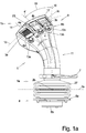
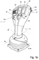
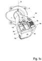
- Fig. 1a - c:
- das Steuerelement in unterschiedlichen Ansichten im Wesentlichen von vorne,
- Fig. 2a - c:
- das Steuerelement in unterschiedlichen Ansichten im Wesentlichen von hinten,
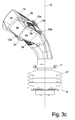
- Fig. 3a - c:
- das Steuerelement in unterschiedlichen Ansichten im Wesentlichen von der Seite,
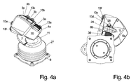
- Fig. 4a
- das Steuerelement von schräg oben in der Aufsicht auf die obere Stirnfläche,
- Fig. 4b
- das Steuerelement von unten,
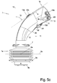
- Fig. 5a, b:
- das Steuerelement im Wesentlichen von vorne mit haltender Hand
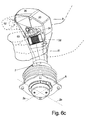
- Fig. 6a - d:
- das Steuerelement im Wesentlichen von hinten mit haltender Hand.
- Das in den Figuren dargestellte Steuerelement besteht aus dem Steuerknüppel 1, welcher gemäß der
Figuren 5 und6 von der Hand 50 des Bedieners gehalten werden soll, und einem Basiskörper 8, welches der Befestigung des Steuerknüppels an einem Bauteil der Umgebung dient, und von dessen Oberseite der Steuerknüppel 1 mittels eines Gelenkes befestigt ist und nach oben ragt. - Das Basisteil 8 besitzt entweder eine ebene Oberseite 8a und/oder eine ebene Unterseite 8b, zumindest an der Befestigungsplatte des Basisteiles 8, welches der Verschraubung gegenüber einem anderen Bauteil dient.
- Diese ebene Oberseite 8a oder 8b, in diesem Fall die Ebene der Befestigungsplatte, wird für die Zwecke der vorliegenden Anmeldung als die horizontale Ebene angenommen, da der Basiskörper meist auf einer horizontalen Fläche befestigt wird.
- Analog dazu wird die Lotrechte auf diese ebene Oberseite oder Unterseite 8a, b des Basiskörpers 8 als Vertikale 10 definiert.
- Der Steuerknüppel 1 ist auf der Oberseite des Basiskörpers 8 verschwenkbar um zwei im Winkel zueinander stehende und vorzugsweise in der Horizontalen liegende Schwenkachsen 2a,b verschwenkbar befestigt, wobei das diesbezügliche Gelenk in einem üblichen Gummibalg 27 angeordnet ist.
- Diese beiden Verschwenkungsrichtungen des Steuerknüppels 1 stellen die ersten beiden proportionalen Betätigungsmöglichkeiten dar, denn dadurch können zwei Bewegungsfunktionen eines Arbeitsgerätes gesteuert werden, beispielsweise Vorwärts- oder Rückwärtsbewegung und Auslenken nach links oder rechts.
- Für viele Arbeitsmaschinen, die mit einem solchen Steuerknüppel gesteuert werden sollen, ist jedoch eine weitaus größere Anzahl von proportionalen als auch digitalen Steuerungsmöglichkeiten notwendig, weshalb auf dem Steuerknüppel eine Vielzahl solcher Betätigungselemente untergebracht sind, die mit den Fingern des den Steuerknüppel 1 haltenden Hand eines Benutzers - wie in den
Figuren 5 und6 dargestellt - betätigt werden können. - Zu diesem Zweck besitzt der Steuerknüppel 1 einen vom Basiskörper 8 aufragenden, vergleichsweise schmalen, Schaft 11, der sich zum Betätigungsende 1b des Steuerknüppels 1 hin zu einem Kopf 9 verbreitert, damit vor allem auf der dadurch im Bereich des Kopfes 9 verbreiterten Frontfläche 4 des Steuerknüppels 1 mehrere weitere Betätigungselemente untergebracht werden können:
- Damit die diese Betätigungselemente betätigenden Finger der Hand des Benutzers sich dafür in der richtigen Lage befinden, ist am unteren Ende, nahe dem Betätigungsende 1a des Steuerknüppels 1, eine Handauflage 7 am Schaft 11 befestigt, welche zumindest auf einer Seite, für einen Rechtshänder auf der rechten Seite, vom Schaft 11 radial vorsteht, wie am besten in
Fig. 1b und4a zu erkennen: - Darauf kann die den Steuerknüppel führende Hand des Benutzers mit der dem Daumen gegenüberliegenden Schmalseite des Handtellers aufgelegt werden, und zur Anpassung an die Größe dieser Hand ist die Handauflage 7 in Längsrichtung, also im Wesentlichen in Richtung der Vertikalen 10, entlang des Schaftes 11 verstellbar und arretierbar, beispielsweise durch Lösen oder Anziehen einer Klemmschraube in der ringförmig ausgebildeten Handauflage 7.
- Der Steuerknüppel 1 wird dabei bei der Bedienung von der Hand 50 des Benutzers in einem Klammergriff gehalten, so dass sich nur der Daumen auf der Frontfläche 4 des Steuerknüppels 1, insbesondere dessen Kopfes 9, befindet.
- Um eine natürliche, ermüdungsfreie Haltung der führenden Hand 50 zu ermöglichen, ist der Steuerknüppel 1 und damit auch dessen Frontfläche 4 nicht gerade ausgebildet, sondern in mehrere Richtungen gebogen:
- Wie
Fig. 4a in der Seitenansicht erkennen lässt, ist die Frontfläche 4 am unteren Ende des Schaftes 11 noch vertikal oder annähernd vertikal ausgerichtet, und verläuft von dort konvex bogenförmig, so dass die Frontfläche 4 am Befestigungsende 1b gegenüber der Vertikalen 10 einen Frontflächen-Winkel 16 von etwa 53° bis 65° einnimmt, und dieser Winkel annähernd über die gesamte Erstreckung des Kopfes 9 gleichbleibt, indem sich die frontseitigen Betätigungselemente befinden. - Wie am besten
Fig. 1a zeigt, ragt der Steuerknüppel 1 auch in der Frontansicht betrachtet nicht gerade nach oben auf, sondern ist - der vorliegende Steuerknüppel ist für einen Rechtshänder gestaltet, für einen Linkshänder wäre es genau umgekehrt - vom Befestigungsende 1a aus nach links oben gekrümmt. - Zeichnet man auf der Mitte der Frontfläche 4 eine Längsmitte 4' ein, die von der Mitte am Betätigungsende 1b zur Mitte am Befestigungsende 1a in der Frontansicht reicht, so steht diese Längsmitte 4' am oberen Ende der Frontfläche 4 unter einem Seitenneigungs-Winkel 19 von 27° bis 37° zur Vertikalen 10.
- Die obere Endkante der Frontfläche 4 ist ebenfalls konvex bogenförmig gestaltet, so dass sich ihr höchster oberster Punkt 17 am rechten Ende dieser Endkante befindet und sie von dort aus nach links bogenförmig abfällt.
- In der Aufsicht der
Fig. 1a und auch weiteren Frontansichten betrachtet ist das Schwenkteil 1 also etwa birnenförmig gestaltet, wobei Frontfläche 4, die Seitenflächen 6a,b und die Rückfläche 5 durchaus in nur wenig gerundeten Kanten ineinander übergehen, was jedoch keine Bedingung für die erfindungsgemäßen Merkmale dieses Steuerknüppels ist. - In den vorliegenden Zeichnungen sind als proportionale Betätigungselemente Scrollräder - also Räder, deren Drehachse unter der Oberfläche, in diesem Fall der Frontfläche 4, liegen und die vorzugsweise aus dieser heraus vorstehen und verdreht werden können - eingezeichnet oder lediglich die Aufnahmeöffnung für ein solches proportionales Betätigungselement im Gehäuse des Schwenkteiles 1, und als digitale Betätigungselemente Drucktasten.
- Um möglichst viele Betätigungselemente unterzubringen, sind auf der Frontfläche 4 nebeneinander drei proportionale Betätigungselemente 3a,b angeordnet, die jeweils nahe des oberen Endes der Frontfläche, und mit ihrer Ausrichtung, also ihrer Bewegungsrichtung 14, nicht parallel zueinander sondern in einem sich nach oben öffnenden Winkel.
- Die Bewegungsrichtung 14 des linken proportionalen Betätigungselementes 3a steht dabei in einem Schrägwinkel 21 von etwa 10° bis 20° zur Längsmitte 4' der Frontfläche 4.
- Die Mittelpunkte der proportionalen Betätigungselemente 3a, b, c sind auf einem Kreisbogen 12 angeordnet, dessen Mittelpunkt 14 etwa im Bereich des Überganges zwischen Kopf 9 und Schaft 11 sitzt, also bei einer den Steuerknüppel 1 führenden Hand 50 des Benutzers etwa im Bereich dessen Daumengelenkes. Bei ausgestrecktem Daumen liegt dieser also wahlweise auf einem der proportionalen Betätigungselemente 3a, b, c auf.
- Unterhalb jedes der drei proportionalen Betätigungselemente 3a, b, c ist jeweils ein digitales Betätigungselement 13a, b, c angeordnet, so dass der Daumen zum Betätigen dieser digitalen Betätigungselemente 13a, b, c gekrümmt werden muss.
- Zusätzlich ist der linke Teil der Frontfläche 4, die linke Daumenfläche 4a, tiefergesetzt als gegenüber der rechten Daumenfläche 4b, in der sich je zwei proportionale und digitale Betätigungselemente befinden, da dies für die Betätigung durch den Daumen einfacher ist.
- In dem Absatz 22 dazwischen, und im Bereich zwischen dem ersten und zweiten proportionalen Betätigungselement 3a bzw. 3b ragt aus der Frontfläche 4 eine Daumenauflage 23 in Form eines erhabenen, etwa in Längsmitte 4' verlaufenden, Steges nach oben, und zwar weiter als die daneben liegenden Betätigungselemente nach oben ragen.
- Der Daumen muss also bei Nichtbenutzung nicht starr in der Luft gehalten werden, sondern kann gezielt auf der Daumenauflage 23 abgelegt werden, um Ermüdungserscheinungen vorzubeugen.
- Wie am besten die
Figuren 2a ,b ,c zeigen, sind auf der Rückfläche 5 des Steuerknüppels 1 weitere Betätigungselemente untergebracht: Zum einen ein proportionales Betätigungselement 3d, dessen Bewegungsrichtung 14 etwa horizontal angeordnet ist und welches sich im unteren Bereich des Kopfes 9, also fast schon im Übergang zum Schaft 11, befindet. - Wie
Fig. 3a zeigt, verläuft die Rückfläche 5 des Steuerknüppels 1 in etwa parallel zur Frontfläche 4, so dass sich die Dicke des Steuerknüppels1 vom unteren Befestigungsende 1a zum oberen Betätigungsende 1b nur geringfügig verbreitert. - Wie
Fig. 3a ferner erkennen lässt, befindet sich das besagte proportionale Betätigungselement 3d in der nach oben weisenden Flanke einer Aufwölbung 26 in der Rückfläche 5, die die ansonsten konkave Kontur der Rückfläche 5 in der Seitenansicht unterbricht durch ihre konvexe Gestalt. Dadurch kann der Mittelfinger 53, der dieses proportionale Betätigungselement 3d betätigen soll - wie am besten inFig. 6 a zu erkennen - ohne Verkrampfung dort aufgelegt und bewegt werden. - Im Abstand darüber ist - siehe
Fig. 2a - ein weiteres digitales Betätigungselement 13d angeordnet, welches vorzugsweise ebenfalls vom Mittelfinger 53 - sieheFig. 6a ,b - betätigt werden kann, zur Not aber auch vom Zeigefinger 52. - Zwischen den beiden Betätigungselementen befindet sich eine Mittelfinger-Ablage 24 in Form eines etwa in horizontaler Richtung verlaufenden, sich von der Rückfläche 5 aufwölbenden Steges, der höher aufgewölbt ist als die daneben befindlichen beiden Betätigungselemente 13d und 3d und als entspannte Ablage für den nicht benutzten Mittelfinger 53 oder Zeigefinger 52 dient.
- Zusätzlich sind bei diesem Steuerknüppel auch in der - für Rechtshänder - rechten Seitenfläche 6b Betätigungselemente untergebracht, die vom ausgestreckt nach oben ragenden Zeigefinger 52 erreicht und betätigt werden können:
- Wie am besten in
Fig. 2b ,c undFig. 3a ersichtlich, handelt es sich dabei um zwei digitale Betätigungselemente 13e, 13f, die nahe des oberen Endes der Seitenfläche 6b und nahe zur Rückfläche 5 hin nebeneinander angeordnet sind, so dass das eine fast unmittelbar neben der Rückfläche 5 angeordnet ist, das andere etwas weiter in Richtung Frontfläche 4. - Diese beiden Drucktaster 13e, f sind auf Teilbereichen 6b1, 6b2 der Seitenfläche 6b angeordnet, die in einem Außenwinkel 29 von etwa 185° bis 215°, besser 195° bis 209°, zueinander stehen, was die Unterscheidbarkeit der beiden Drucktaster durch den Bediener allein sensorisch erleichtert.
- In den
Figuren 5 und6 ist zusätzlich die jeweils den Steuerknüppel führende Hand eingezeichnet: - Wie
Fig. 5a ,b mit Blickrichtungen von der Vorderseite her verdeutlicht, umgreift die Hand 50 des Benutzers zumindest mit Mittelfinger, Ringfinger und kleinem Finger den Schaft 11 des Steuerknüppel des 1, und liegt dabei mit dem Handballen auf der Oberseite der Hand Auflage 7 auf. - In
Figur 5a betätigt der auf der Vorderseite liegende Daumen das rechte proportionale Betätigungselement 3c oder das darunter liegende digitale Betätigungselement 13c, inFigur 5b dagegen das linke digitale Betätigungselement 13a. - In den
Figuren 6a -d sind diverse Handhaltungen betrachtet von der Rückseite des Steuerknüppels 1 dargestellt: - In
Figur 6a umschließen Ringfinger und kleiner Finger den Schaft 11, während der Mittelfinger 53 auf dem rückseitigen proportionalen Betätigungselement 13d liegt und dieses betätigen kann. Der Zeigefinger 52 liegt auf dem rückseitigen digitalen Betätigungselement 13d und kann dieses betätigen. - In
Figur 6b dagegen umschließen ebenfalls Ringfinger und Zeigefinger 52 den Schaft 11, der Mittelfinger 53 liegt nun jedoch abgelegt auf der Mittelfinger-Auflage 24 der Rückseite, und ist inaktiv, während der Zeigefinger 52 in der Ablagerinne 28 auf der Rückseite, die zwischen dem rückseitigen digitalen Betätigungselement 13d und der im Abstand darüber angeordneten Aufwölbung 25, die für das seitliche digitale Betätigungselement 13f ausgebildet ist. - In
Figur 6c unterscheidet sich die Handhaltung gegenüberFigur 6b dadurch, dass hier der Zeigefinger gekrümmt das digitale Betätigungselement 13f betätigt, welches im oberen Bereich der Seitenfläche 6b angeordnet ist. - In
Figur 6d ist Handhaltung von Mittelfinger 53 und Zeigefinger 52 nochmals anders, indem der Mittelfinger 53 auf dem rückseitige digitale Betätigungselement 13d liegt, während der Zeigefinger 52 dabei ist, das auf der Seitenfläche 6b angeordnete, weiter vorn liegende der beiden digitalen Betätigungselemente 13e, f zu betätigen. -
- 1
- Steuerknüppel
- 1a
- Befestigungs-Ende
- 1b
- Betätigungs-Ende
- 2a, b
- Schwenkachse
- 3a, b
- proportionales Betätigungselement, Schieber
- 4
- Frontfläche
- 4'
- Längsmitte
- 4a
- linke Daumenfläche
- 4b
- rechte Daumenfläche
- 5
- Rückfläche
- 6a, b
- Seitenfläche
- 6b1, 6b2
- Teilbereich
- 7
- Handauflage
- 8
- Basiskörper
- 9
- Kopf
- 10
- Längsrichtung, Vertikale
- 11
- Schaft
- 12
- Kreisbogen
- 13
- digitales Betätigungselement, Druckschalter
- 14
- Bewegungsrichtung
- 15
- Mittelpunkt
- 16
- Frontflächen-Winkel
- 17
- oberster Punkt
- 18
- Krümmungsradius
- 19
- Seitenneigungs-Winkel
- 20
- Stirnfläche
- 21
- Schräg-Winkel
- 22
- Absatz
- 23
- Daumen-Auflage
- 24
- Mittelfinger-Auflage
- 25
- Aufwölbung
- 26
- Aufwölbung
- 27
- Gummibalg
- 28
- Ablagerinne
- 29
- Außenwinkel
- 50
- Hand
- 51
- Daumen
- 52
- Zeigefinger
- 53
- Mittelfinger
Claims (16)
- Steuerelement mit- einem Basiskörper (8), an dem ein Steuerknüppel (1) als erstes proportionales Betätigungselement mit seinem einen Befestigungs-Ende (1a) um zwei im Winkel zueinander stehende, meist horizontal liegende, Schwenkachsen (2a, b) stufenlos schwenkbar ist,- der Steuerknüppel (1) an dem vom Befestigungsende (1a) gegenüber liegenden Betätigungs-Ende (1b) einen verbreiterten Kopf (9) und einen sich von dort zum Befestigungsende (1a) hin verlaufenden Schaft (11) umfasst,- der Steuerknüppel (1) eine konvex gekrümmte, in der Regel dem Benutzer zugewandte, Frontfläche (4), eine dieser gegenüber liegende, konkav gekrümmte, Rückfläche (5) und diese beiden Flächen (4, 5) an den Seiten verbindende linke und rechte Seitenflächen (6a, b) aufweist unddadurch gekennzeichnet, dass
weitere, insbesondere proportionale, Betätigungselemente (3a, b)- in der Frontfläche (4)- auf der Rückfläche (5)- und gegebenenfalls auch auf der rechten Seitenfläche (6b) im Bereich des Kopfes (9)angeordnet sind. - Steuerelement nach Anspruch 1,
dadurch gekennzeichnet, dass
die Betätigungselemente im Übergangsbereich zwischen Kopf (9) und Schaft (11) angeordnet sind.
(Frontfläche) - Steuerelement nach einem der vorhergehenden Ansprüche,
dadurch gekennzeichnet, dass
in der Seitenansicht die Frontfläche (4) an ihrem unteren Ende etwa in Richtung der Vertikalen (10), der lotrechten auf die ebene Unterseite (8b) oder Oberseite (8a) des Basiskörpers (8), verläuft und einen Frontflächen-Winkel (16) zur Vertikalen (10) einnimmt, der zwischen 45 ° und 75° beträgt, besser zwischen 53° und 65°. - Steuerelement nach einem der vorhergehenden Ansprüche,
dadurch gekennzeichnet, dass
in der Frontansicht betrachtet die in der Mitte zwischen den beiden Seitenflächen (6a, b) auf der Frontfläche (4) verlaufende Längsmitte (4') bogenförmig gekrümmt ist und gegenüber der Vertikalen (10) am oberen Ende einen Seitenneigungs-Winkel (19) einnimmt, der zwischen 15° und 46°, besser zwischen 27° und 37° beträgt. - Steuerelement nach einem der vorhergehenden Ansprüche,
dadurch gekennzeichnet, dass
In der Frontansicht betrachtet die Oberkante der Frontfläche (4) von ihrem obersten Punkt (17) im rechten Endbereich nach links unten abfällt, insbesondere bogenförmig konvex, abfällt. - Steuerelement nach einem der vorhergehenden Ansprüche,
dadurch gekennzeichnet, dass
drei der weiteren proportionalen Betätigungselemente (3a, b, c) auf der Frontfläche (4) angeordnet sind. - Steuerelement nach einem der vorhergehenden Ansprüche,
dadurch gekennzeichnet, dass
die Frontfläche (4) aus einer rechten und einer linken Daumenfläche (4a, b) besteht, wobei zwischen beiden ein etwa parallel zur Längsmitte (4') verlaufender Absatz (22) vorhanden ist und insbesondere die bei Betrachtung auf die Frontfläche (4) linke Daumenfläche (4a) tiefer liegt als die rechte Daumenfläche (4b), und insbesondere eines der weiteren proportionalen Betätigungselement (3a) auf der linken Daumenfläche (4a) und zwei der weiteren proportionalen Betätigungselemente (3b, c) auf der rechten Daumenfläche (4b) angeordnet sind. - Steuerelement nach einem der vorhergehenden Ansprüche,
dadurch gekennzeichnet, dass
im Bereich der weiteren proportionalen Betätigungselemente (3a, b) dazwischen im Bereich des Absatzes (22) eine Daumenauflage (23) aus der Frontfläche (4) vorsteht und höher aufragt als die rechts und links daneben befindlichen proportionalen Betätigungselemente (3a, b)
und/oder
das wenigstens eine weitere proportionale Betätigungselement (3a, b) auf der Frontfläche (4) entweder ein Scrollrad ist, welches zum Teil über die Frontfläche (4) vorsteht oder ein Schieber ist, der entlang der Frontfläche (4) verschiebbar ist. - Steuerelement nach einem der vorhergehenden Ansprüche,
dadurch gekennzeichnet, dass
der Steuerknüppel (1) in seinem unteren Bereich am Schaft (11) eine radial wenigstens auf einer Seite vorstehende, insbesondere umlaufende, Handauflage (7) aufweist, die in der Höhe relativ zum Schwenkteil (1) verstellbar und fixierbar, insbesondere verrastbar, ist
und/oder
die weiteren proportionalen Betätigungselemente (3a, b, c) auf der Frontfläche (4) im Bereich des Daumens (51) einer den Steuerknüppel (1) führenden und auf der Handauflage (7) aufgelegten Hand (50) angeordnet sind und insbesondere auf einem Kreisbogen (12) um einen Mittelpunkt (13), der im mittleren Höhen-Bereich der Frontfläche (4) angeordnet ist. - Steuerelement nach einem der vorhergehenden Ansprüche,
dadurch gekennzeichnet, dass
die Bewegungsrichtung (14) der proportionalen Betätigungselemente (3a, b, c) auf der Frontfläche (4) maximal um einen Schrägwinkel (21) von plus/minus 20°, besser nur von plus/minus 15°, besser nur von plus/minus 10°, von der Längsmitte (4') entlang der Frontfläche (4) in diesem Höhenbereich abweicht
und/oder
auf der Frontfläche (4) im Bereich des Kopfes (9) mehrere, insbesondere drei, digitale Betätigungselemente (6a, b, c) im Bereich des Daumens (51) einer auf der Handauflage (7) ruhenden und den Steuerknüppel (1) haltenden Hand (50) angeordnet sind, und insbesondere je eines der digitalen Betätigungselemente (13a, b, c) unterhalb je eines der drei proportionalen Betätigungselemente (3a, b, c) angeordnet ist.
(Rückfläche) - Steuerelement nach einem der vorhergehenden Ansprüche,
dadurch gekennzeichnet, dass
das wenigstens eine (3d) der weiteren proportionalen Betätigungselemente auf der Rückfläche (5) des Schwenkteiles (1) im Griffbereich des Mittelfingers (53) einer auf der Handauflage (7) ruhenden und den Schwenkteil (1) haltenden Hand (50) angeordnet ist und insbesondere die Bewegungsrichtung (14) dieses weiteren proportionalen Betätigungselementes (3b) im Wesentlichen waagrecht ist. - Steuerelement nach einem der vorhergehenden Ansprüche,
dadurch gekennzeichnet, dass
ein weiteres digitales Betätigungselement (13d) auf der Rückfläche (5) im Griffbereich des Zeigefingers (52) und/oder Mittelfingers (53) einer auf der Handauflage (7) ruhenden und den Schwenkteil (1) haltenden Hand (50) angeordnet ist, und insbesondere oberhalb des auf der Rückfläche (5) angeordneten proportionalen Betätigungselements (3b)
und/oder
zwischen dem digitalen Betätigungselement (13d) und dem proportionalen - Betätigungselement (3d) auf der Rückfläche (5) eine insbesondere in der Waagrechten verlaufende Mittelfinger-Auflage (24) von der Rückfläche (5) vorsteht und weiter vorsteht als die beiden benachbarten Betätigungselemente (13d, 3d). - Steuerelement nach einem der vorhergehenden Ansprüche,
dadurch gekennzeichnet, dass
von der Rückfläche (5) in deren obersten Bereich und in der rechten Seitenfläche (6b) mündend eine Aufwölbung (25) vorhanden ist, sodass zwischen der Auflage (25) und dem im Abstand darunter angeordneten digitalen Betätigungselement (13d) auf der Rückfläche (5) eine Ablagerinne (28) für einen Finger gebildet wird
und/oder
in der Seitenansicht von rechts betrachtet von der Rückfläche (5) am Übergang zwischen dem Kopf (9) und dem Schaft (11), unterhalb des proportionalen Betätigungselementes (3d) eine Aufwölbung (26) in der Rückfläche (5) vorhanden ist, und das proportionale Betätigungselement (3d) insbesondere in der nach oben weisenden Flanke der Aufwölbung (26) angeordnet ist.
(Seitenfläche) - Steuerelement nach einem der vorhergehenden Ansprüche,
dadurch gekennzeichnet, dass
in der rechten Seitenfläche (6b) nahe des Betätigungsendes (1b) des Schwenkteiles (1) wenigstens ein, vorzugsweise mehrere, digitale Betätigungselemente (13e, f) angeordnet sind, die sich vorzugsweise näher an der Rückfläche (5) als an der Frontfläche (4) befinden und sich in ihrem Abstand zur Rückfläche (5) unterscheiden aber vorzugsweise im gleichen Abstand zum Befestigungsende (1b), der Stirnfläche (20), des Steuerknüppels (1) angeordnet sind. - Steuerelement nach einem der vorhergehenden Ansprüche,
dadurch gekennzeichnet, dass
die Teilbereiche (6b1, 6b2) der rechten Seitenfläche (6b), in denen die beiden digitalen Betätigungselemente (13e, f) angeordnet sind, in einem Außenwinkel (29) von 185° bis 215°, besser von 195° bis 209°, zueinander stehen.
(Allgemein) - Steuerelement nach einem der vorhergehenden Ansprüche,
dadurch gekennzeichnet, dass
der Basiskörper (8) eine Höhe von maximal 3,0 cm, maximal 2,5 cm, besser maximal nur 2 cm, besser nur maximal 1,5 cm, besitzt
und/oder
in der Seitenansicht betrachtet der Kopf (9) des Steuerknüppels (1) eine Dicke zwischen 5,0 cm und 7,0 cm, besser zwischen 5,5 cm und 6,5 cm, gemessen zwischen Frontfläche (4) und Rückfläche (5), besitzt.
und/oder
in der Frontansicht betrachtet der Kopf (9) des Steuerknüppels (1) eine größte Breite zwischen 7,0 cm und 10,0 cm, besser zwischen 8,0 cm und 9,0 cm, gemessen zwischen linker und rechter Seitenfläche (6a, b), besitzt.
Applications Claiming Priority (1)
| Application Number | Priority Date | Filing Date | Title |
|---|---|---|---|
| DE202015103509.8U DE202015103509U1 (de) | 2015-07-03 | 2015-07-03 | Steuerelement |
Publications (3)
| Publication Number | Publication Date |
|---|---|
| EP3115863A2 true EP3115863A2 (de) | 2017-01-11 |
| EP3115863A3 EP3115863A3 (de) | 2017-01-25 |
| EP3115863B1 EP3115863B1 (de) | 2019-08-07 |
Family
ID=53782936
Family Applications (1)
| Application Number | Title | Priority Date | Filing Date |
|---|---|---|---|
| EP16175706.7A Active EP3115863B1 (de) | 2015-07-03 | 2016-06-22 | Steuerelement |
Country Status (2)
| Country | Link |
|---|---|
| EP (1) | EP3115863B1 (de) |
| DE (1) | DE202015103509U1 (de) |
Cited By (8)
| Publication number | Priority date | Publication date | Assignee | Title |
|---|---|---|---|---|
| FR3115615A1 (fr) * | 2020-10-22 | 2022-04-29 | Airbus Operations (S.A.S.) | Minimanche pourvu d’un support a hauteur reglable |
| US20220136210A1 (en) * | 2020-11-04 | 2022-05-05 | Caterpillar Inc. | Machine control component with input device to control machine display |
| US20220195697A1 (en) * | 2020-12-21 | 2022-06-23 | Caterpillar Inc. | Manual input device and method |
| FR3124610A1 (fr) * | 2021-06-29 | 2022-12-30 | Kuhn-Audureau Sas | Dispositif de commande d’une ou plusieurs fonction(s) de travail d’une machine agricole et machine agricole munie dudit dispositif de commande |
| US12269579B2 (en) | 2020-06-05 | 2025-04-08 | Joby Aero, Inc. | Aircraft control system and method |
| DE102024113159A1 (de) * | 2024-05-10 | 2025-11-13 | Mulag Fahrzeugwerk Heinz Wössner GmbH u. Co KG | Steuervorrichtung mit Steuerhebel |
| EP4649797A1 (de) | 2024-05-17 | 2025-11-19 | Mulag Fahrzeugwerk Heinz Wössner GmbH u. Co. KG | Steuervorrichtung und fahrzeugsteuersystem mit gateway |
| WO2026074783A1 (ja) * | 2024-10-02 | 2026-04-09 | Astemo株式会社 | 操舵入力装置及びステアバイワイヤ式の操舵装置 |
Families Citing this family (3)
| Publication number | Priority date | Publication date | Assignee | Title |
|---|---|---|---|---|
| JP6574515B1 (ja) * | 2017-11-24 | 2019-09-11 | 株式会社小松製作所 | 操作レバー及び作業車両 |
| US11614766B2 (en) | 2020-04-09 | 2023-03-28 | Caterpillar Inc. | Machine joystick with comfort and accessibility features |
| US11573591B2 (en) | 2020-04-10 | 2023-02-07 | Caterpillar Inc. | Machine joystick with ergonomic features |
Family Cites Families (13)
| Publication number | Priority date | Publication date | Assignee | Title |
|---|---|---|---|---|
| US5042314A (en) * | 1989-11-02 | 1991-08-27 | Caterpillar Inc. | Steering and transmission shifting control mechanism |
| US6550562B2 (en) * | 2000-12-08 | 2003-04-22 | Clark Equipment Company | Hand grip with microprocessor for controlling a power machine |
| DE10127515C2 (de) * | 2001-06-06 | 2003-05-22 | Itt Mfg Enterprises Inc | Schaltgriff |
| DE10140975A1 (de) * | 2001-08-27 | 2003-03-20 | Claas Selbstfahr Erntemasch | Vorrichtung zum Steuern eines landwirtschaftlichen Fahrzeugs |
| DE10217039B3 (de) * | 2002-04-12 | 2004-02-26 | Fernsteuergeräte Kurt Oelsch GmbH | Steuergriff mit Betätigungseinheiten |
| DE102004006947A1 (de) * | 2004-02-12 | 2005-09-01 | Still Gmbh | Bedienanordnung einer mobilen Arbeitsmaschine |
| US7497298B2 (en) * | 2004-06-22 | 2009-03-03 | Caterpillar Inc. | Machine joystick control system |
| FR2898205A1 (fr) * | 2006-03-01 | 2007-09-07 | Bosch Rexroth D S I Soc Par Ac | Telecommande d'engin mobile, en particulier engin de travaux publics, engin agricole ou de manutention |
| DE102006022967B3 (de) * | 2006-05-11 | 2007-12-06 | ITT Manufacturing Enterprises, Inc., Wilmington | Schaltgriff |
| US20080230364A1 (en) * | 2006-05-15 | 2008-09-25 | Paul Treuthardt | Joystick control device |
| EP2212755B1 (de) * | 2007-10-08 | 2023-05-10 | Svab Hydraulik AB | Steuerhebel zum betreiben einer maschine, verfahren zum betreiben der maschine über einen steuerhebel und verwendung des steuerungshebels |
| JP5363527B2 (ja) * | 2011-04-28 | 2013-12-11 | 栄通信工業株式会社 | 位置入力制御装置 |
| SE537133C2 (sv) * | 2013-05-22 | 2015-02-10 | Microprop Ab | Manöverorgan |
-
2015
- 2015-07-03 DE DE202015103509.8U patent/DE202015103509U1/de not_active Expired - Lifetime
-
2016
- 2016-06-22 EP EP16175706.7A patent/EP3115863B1/de active Active
Non-Patent Citations (1)
| Title |
|---|
| None |
Cited By (13)
| Publication number | Priority date | Publication date | Assignee | Title |
|---|---|---|---|---|
| US12269579B2 (en) | 2020-06-05 | 2025-04-08 | Joby Aero, Inc. | Aircraft control system and method |
| FR3115615A1 (fr) * | 2020-10-22 | 2022-04-29 | Airbus Operations (S.A.S.) | Minimanche pourvu d’un support a hauteur reglable |
| US11866909B2 (en) * | 2020-11-04 | 2024-01-09 | Caterpillar Inc. | Machine control component with input device to control machine display |
| US20220136210A1 (en) * | 2020-11-04 | 2022-05-05 | Caterpillar Inc. | Machine control component with input device to control machine display |
| US20220195697A1 (en) * | 2020-12-21 | 2022-06-23 | Caterpillar Inc. | Manual input device and method |
| US11828043B2 (en) * | 2020-12-21 | 2023-11-28 | Caterpillar Inc. | Manual input device and method |
| FR3124610A1 (fr) * | 2021-06-29 | 2022-12-30 | Kuhn-Audureau Sas | Dispositif de commande d’une ou plusieurs fonction(s) de travail d’une machine agricole et machine agricole munie dudit dispositif de commande |
| EP4116796A1 (de) * | 2021-06-29 | 2023-01-11 | Kuhn-Audureau SAS | Vorrichtung zur steuerung einer oder mehrerer arbeitsfunktionen einer landmaschine und landmaschine mit dieser steuerungsvorrichtung |
| DE102024113159A1 (de) * | 2024-05-10 | 2025-11-13 | Mulag Fahrzeugwerk Heinz Wössner GmbH u. Co KG | Steuervorrichtung mit Steuerhebel |
| EP4649797A1 (de) | 2024-05-17 | 2025-11-19 | Mulag Fahrzeugwerk Heinz Wössner GmbH u. Co. KG | Steuervorrichtung und fahrzeugsteuersystem mit gateway |
| DE102024113986A1 (de) * | 2024-05-17 | 2025-11-20 | Mulag Fahrzeugwerk Heinz Wössner GmbH u. Co KG | Steuervorrichtung und Fahrzeugsteuersystem mit Gateway |
| DE102024113986B4 (de) * | 2024-05-17 | 2025-12-18 | Mulag Fahrzeugwerk Heinz Wössner GmbH u. Co KG | Steuervorrichtung und Fahrzeugsteuersystem mit Gateway |
| WO2026074783A1 (ja) * | 2024-10-02 | 2026-04-09 | Astemo株式会社 | 操舵入力装置及びステアバイワイヤ式の操舵装置 |
Also Published As
| Publication number | Publication date |
|---|---|
| EP3115863A3 (de) | 2017-01-25 |
| EP3115863B1 (de) | 2019-08-07 |
| DE202015103509U1 (de) | 2015-07-21 |
Similar Documents
| Publication | Publication Date | Title |
|---|---|---|
| EP3115863B1 (de) | Steuerelement | |
| DE3224208C2 (de) | ||
| DE60005718T2 (de) | Griff für Mähgerät | |
| EP2277369A1 (de) | Multifunktionsgriff | |
| DE102015117621B3 (de) | Anordnung zur Verbindung eines Schraubenschlüssels mit einer Aufnahmevorrichtung | |
| DE102010007193B4 (de) | Tragbare TopHandle-Arbeitsmaschine | |
| DE202013103745U1 (de) | Heckenschere | |
| DE60121728T2 (de) | Anordnung in verbindung mit einer steuerungseinrichtung | |
| EP0943976A2 (de) | Handbetätigte Stellvorrichtung für einen Bedienungsstand bzw. -sitz | |
| EP2880503B1 (de) | Handbedienelement, insbesondere für eine baumaschine | |
| AT513483B1 (de) | Besteckteil mit längenveränderbarem Stiel | |
| DE4206515C1 (de) | ||
| WO2021224181A1 (de) | Eingabevorrichtung | |
| EP0586029B1 (de) | Hebezeug mit einer Hubvorrichtung | |
| DE4033692A1 (de) | Handwerkzeug | |
| DE60011786T2 (de) | Betätigungsvorrichtung für Arbeitsfahrzeuge | |
| AT11940U1 (de) | Vorrichtung zum steuern von arbeitsgeräten | |
| EP1775254B1 (de) | Bedienpult mit Daumenjoystick für ein Flurförderzeug | |
| EP4227757A1 (de) | Bedienhebel zur steuerung einer komponente, arbeitsmaschine mit dem bedienhebel und verfahren zum steuern der komponente | |
| DE202013104102U1 (de) | Gartenschere mit einer Verstellstruktur für die Öffnungsweite | |
| DE102010015639A1 (de) | Ergonomisches Verstellteil | |
| DE2712805A1 (de) | Buegeleisen | |
| DE2704720C2 (de) | Schnellverstellzirkel | |
| DE4222857C2 (de) | Handrad | |
| EP1747964A2 (de) | Bedienelementeeinheit mit Minihebeln |
Legal Events
| Date | Code | Title | Description |
|---|---|---|---|
| PUAI | Public reference made under article 153(3) epc to a published international application that has entered the european phase |
Free format text: ORIGINAL CODE: 0009012 |
|
| STAA | Information on the status of an ep patent application or granted ep patent |
Free format text: STATUS: THE APPLICATION HAS BEEN PUBLISHED |
|
| PUAL | Search report despatched |
Free format text: ORIGINAL CODE: 0009013 |
|
| AK | Designated contracting states |
Kind code of ref document: A2 Designated state(s): AL AT BE BG CH CY CZ DE DK EE ES FI FR GB GR HR HU IE IS IT LI LT LU LV MC MK MT NL NO PL PT RO RS SE SI SK SM TR |
|
| AX | Request for extension of the european patent |
Extension state: BA ME |
|
| AK | Designated contracting states |
Kind code of ref document: A3 Designated state(s): AL AT BE BG CH CY CZ DE DK EE ES FI FR GB GR HR HU IE IS IT LI LT LU LV MC MK MT NL NO PL PT RO RS SE SI SK SM TR |
|
| AX | Request for extension of the european patent |
Extension state: BA ME |
|
| RIC1 | Information provided on ipc code assigned before grant |
Ipc: G05G 9/047 20060101AFI20161222BHEP Ipc: G05G 1/58 20080401ALN20161222BHEP |
|
| STAA | Information on the status of an ep patent application or granted ep patent |
Free format text: STATUS: REQUEST FOR EXAMINATION WAS MADE |
|
| 17P | Request for examination filed |
Effective date: 20170725 |
|
| RBV | Designated contracting states (corrected) |
Designated state(s): AL AT BE BG CH CY CZ DE DK EE ES FI FR GB GR HR HU IE IS IT LI LT LU LV MC MK MT NL NO PL PT RO RS SE SI SK SM TR |
|
| RIC1 | Information provided on ipc code assigned before grant |
Ipc: G05G 9/047 20060101AFI20181207BHEP Ipc: G05G 1/58 20080401ALN20181207BHEP |
|
| RIC1 | Information provided on ipc code assigned before grant |
Ipc: G05G 1/58 20080401ALN20181221BHEP Ipc: G05G 9/047 20060101AFI20181221BHEP |
|
| GRAP | Despatch of communication of intention to grant a patent |
Free format text: ORIGINAL CODE: EPIDOSNIGR1 |
|
| STAA | Information on the status of an ep patent application or granted ep patent |
Free format text: STATUS: GRANT OF PATENT IS INTENDED |
|
| RIC1 | Information provided on ipc code assigned before grant |
Ipc: G05G 1/58 20080401ALN20181221BHEP Ipc: G05G 9/047 20060101AFI20181221BHEP |
|
| INTG | Intention to grant announced |
Effective date: 20190208 |
|
| GRAS | Grant fee paid |
Free format text: ORIGINAL CODE: EPIDOSNIGR3 |
|
| GRAA | (expected) grant |
Free format text: ORIGINAL CODE: 0009210 |
|
| STAA | Information on the status of an ep patent application or granted ep patent |
Free format text: STATUS: THE PATENT HAS BEEN GRANTED |
|
| AK | Designated contracting states |
Kind code of ref document: B1 Designated state(s): AL AT BE BG CH CY CZ DE DK EE ES FI FR GB GR HR HU IE IS IT LI LT LU LV MC MK MT NL NO PL PT RO RS SE SI SK SM TR |
|
| REG | Reference to a national code |
Ref country code: GB Ref legal event code: FG4D Free format text: NOT ENGLISH |
|
| REG | Reference to a national code |
Ref country code: CH Ref legal event code: EP Ref country code: AT Ref legal event code: REF Ref document number: 1164818 Country of ref document: AT Kind code of ref document: T Effective date: 20190815 |
|
| REG | Reference to a national code |
Ref country code: DE Ref legal event code: R096 Ref document number: 502016005886 Country of ref document: DE |
|
| REG | Reference to a national code |
Ref country code: IE Ref legal event code: FG4D Free format text: LANGUAGE OF EP DOCUMENT: GERMAN |
|
| REG | Reference to a national code |
Ref country code: CH Ref legal event code: NV Representative=s name: SCHMAUDER AND PARTNER AG PATENT- UND MARKENANW, CH |
|
| REG | Reference to a national code |
Ref country code: NL Ref legal event code: MP Effective date: 20190807 |
|
| REG | Reference to a national code |
Ref country code: LT Ref legal event code: MG4D |
|
| PG25 | Lapsed in a contracting state [announced via postgrant information from national office to epo] |
Ref country code: FI Free format text: LAPSE BECAUSE OF FAILURE TO SUBMIT A TRANSLATION OF THE DESCRIPTION OR TO PAY THE FEE WITHIN THE PRESCRIBED TIME-LIMIT Effective date: 20190807 Ref country code: NO Free format text: LAPSE BECAUSE OF FAILURE TO SUBMIT A TRANSLATION OF THE DESCRIPTION OR TO PAY THE FEE WITHIN THE PRESCRIBED TIME-LIMIT Effective date: 20191107 Ref country code: BG Free format text: LAPSE BECAUSE OF FAILURE TO SUBMIT A TRANSLATION OF THE DESCRIPTION OR TO PAY THE FEE WITHIN THE PRESCRIBED TIME-LIMIT Effective date: 20191107 Ref country code: NL Free format text: LAPSE BECAUSE OF FAILURE TO SUBMIT A TRANSLATION OF THE DESCRIPTION OR TO PAY THE FEE WITHIN THE PRESCRIBED TIME-LIMIT Effective date: 20190807 Ref country code: SE Free format text: LAPSE BECAUSE OF FAILURE TO SUBMIT A TRANSLATION OF THE DESCRIPTION OR TO PAY THE FEE WITHIN THE PRESCRIBED TIME-LIMIT Effective date: 20190807 Ref country code: LT Free format text: LAPSE BECAUSE OF FAILURE TO SUBMIT A TRANSLATION OF THE DESCRIPTION OR TO PAY THE FEE WITHIN THE PRESCRIBED TIME-LIMIT Effective date: 20190807 Ref country code: HR Free format text: LAPSE BECAUSE OF FAILURE TO SUBMIT A TRANSLATION OF THE DESCRIPTION OR TO PAY THE FEE WITHIN THE PRESCRIBED TIME-LIMIT Effective date: 20190807 Ref country code: PT Free format text: LAPSE BECAUSE OF FAILURE TO SUBMIT A TRANSLATION OF THE DESCRIPTION OR TO PAY THE FEE WITHIN THE PRESCRIBED TIME-LIMIT Effective date: 20191209 |
|
| PG25 | Lapsed in a contracting state [announced via postgrant information from national office to epo] |
Ref country code: RS Free format text: LAPSE BECAUSE OF FAILURE TO SUBMIT A TRANSLATION OF THE DESCRIPTION OR TO PAY THE FEE WITHIN THE PRESCRIBED TIME-LIMIT Effective date: 20190807 Ref country code: LV Free format text: LAPSE BECAUSE OF FAILURE TO SUBMIT A TRANSLATION OF THE DESCRIPTION OR TO PAY THE FEE WITHIN THE PRESCRIBED TIME-LIMIT Effective date: 20190807 Ref country code: AL Free format text: LAPSE BECAUSE OF FAILURE TO SUBMIT A TRANSLATION OF THE DESCRIPTION OR TO PAY THE FEE WITHIN THE PRESCRIBED TIME-LIMIT Effective date: 20190807 Ref country code: GR Free format text: LAPSE BECAUSE OF FAILURE TO SUBMIT A TRANSLATION OF THE DESCRIPTION OR TO PAY THE FEE WITHIN THE PRESCRIBED TIME-LIMIT Effective date: 20191108 Ref country code: ES Free format text: LAPSE BECAUSE OF FAILURE TO SUBMIT A TRANSLATION OF THE DESCRIPTION OR TO PAY THE FEE WITHIN THE PRESCRIBED TIME-LIMIT Effective date: 20190807 Ref country code: IS Free format text: LAPSE BECAUSE OF FAILURE TO SUBMIT A TRANSLATION OF THE DESCRIPTION OR TO PAY THE FEE WITHIN THE PRESCRIBED TIME-LIMIT Effective date: 20191207 |
|
| PG25 | Lapsed in a contracting state [announced via postgrant information from national office to epo] |
Ref country code: TR Free format text: LAPSE BECAUSE OF FAILURE TO SUBMIT A TRANSLATION OF THE DESCRIPTION OR TO PAY THE FEE WITHIN THE PRESCRIBED TIME-LIMIT Effective date: 20190807 |
|
| PG25 | Lapsed in a contracting state [announced via postgrant information from national office to epo] |
Ref country code: PL Free format text: LAPSE BECAUSE OF FAILURE TO SUBMIT A TRANSLATION OF THE DESCRIPTION OR TO PAY THE FEE WITHIN THE PRESCRIBED TIME-LIMIT Effective date: 20190807 Ref country code: DK Free format text: LAPSE BECAUSE OF FAILURE TO SUBMIT A TRANSLATION OF THE DESCRIPTION OR TO PAY THE FEE WITHIN THE PRESCRIBED TIME-LIMIT Effective date: 20190807 Ref country code: RO Free format text: LAPSE BECAUSE OF FAILURE TO SUBMIT A TRANSLATION OF THE DESCRIPTION OR TO PAY THE FEE WITHIN THE PRESCRIBED TIME-LIMIT Effective date: 20190807 Ref country code: EE Free format text: LAPSE BECAUSE OF FAILURE TO SUBMIT A TRANSLATION OF THE DESCRIPTION OR TO PAY THE FEE WITHIN THE PRESCRIBED TIME-LIMIT Effective date: 20190807 |
|
| PG25 | Lapsed in a contracting state [announced via postgrant information from national office to epo] |
Ref country code: SK Free format text: LAPSE BECAUSE OF FAILURE TO SUBMIT A TRANSLATION OF THE DESCRIPTION OR TO PAY THE FEE WITHIN THE PRESCRIBED TIME-LIMIT Effective date: 20190807 Ref country code: SM Free format text: LAPSE BECAUSE OF FAILURE TO SUBMIT A TRANSLATION OF THE DESCRIPTION OR TO PAY THE FEE WITHIN THE PRESCRIBED TIME-LIMIT Effective date: 20190807 Ref country code: IS Free format text: LAPSE BECAUSE OF FAILURE TO SUBMIT A TRANSLATION OF THE DESCRIPTION OR TO PAY THE FEE WITHIN THE PRESCRIBED TIME-LIMIT Effective date: 20200224 Ref country code: CZ Free format text: LAPSE BECAUSE OF FAILURE TO SUBMIT A TRANSLATION OF THE DESCRIPTION OR TO PAY THE FEE WITHIN THE PRESCRIBED TIME-LIMIT Effective date: 20190807 |
|
| REG | Reference to a national code |
Ref country code: DE Ref legal event code: R097 Ref document number: 502016005886 Country of ref document: DE |
|
| PLBE | No opposition filed within time limit |
Free format text: ORIGINAL CODE: 0009261 |
|
| STAA | Information on the status of an ep patent application or granted ep patent |
Free format text: STATUS: NO OPPOSITION FILED WITHIN TIME LIMIT |
|
| PG2D | Information on lapse in contracting state deleted |
Ref country code: IS |
|
| 26N | No opposition filed |
Effective date: 20200603 |
|
| PG25 | Lapsed in a contracting state [announced via postgrant information from national office to epo] |
Ref country code: SI Free format text: LAPSE BECAUSE OF FAILURE TO SUBMIT A TRANSLATION OF THE DESCRIPTION OR TO PAY THE FEE WITHIN THE PRESCRIBED TIME-LIMIT Effective date: 20190807 |
|
| PG25 | Lapsed in a contracting state [announced via postgrant information from national office to epo] |
Ref country code: MC Free format text: LAPSE BECAUSE OF FAILURE TO SUBMIT A TRANSLATION OF THE DESCRIPTION OR TO PAY THE FEE WITHIN THE PRESCRIBED TIME-LIMIT Effective date: 20190807 |
|
| GBPC | Gb: european patent ceased through non-payment of renewal fee |
Effective date: 20200622 |
|
| PG25 | Lapsed in a contracting state [announced via postgrant information from national office to epo] |
Ref country code: LU Free format text: LAPSE BECAUSE OF NON-PAYMENT OF DUE FEES Effective date: 20200622 |
|
| REG | Reference to a national code |
Ref country code: BE Ref legal event code: MM Effective date: 20200630 |
|
| PG25 | Lapsed in a contracting state [announced via postgrant information from national office to epo] |
Ref country code: GB Free format text: LAPSE BECAUSE OF NON-PAYMENT OF DUE FEES Effective date: 20200622 Ref country code: IE Free format text: LAPSE BECAUSE OF NON-PAYMENT OF DUE FEES Effective date: 20200622 |
|
| PG25 | Lapsed in a contracting state [announced via postgrant information from national office to epo] |
Ref country code: BE Free format text: LAPSE BECAUSE OF NON-PAYMENT OF DUE FEES Effective date: 20200630 |
|
| PG25 | Lapsed in a contracting state [announced via postgrant information from national office to epo] |
Ref country code: MT Free format text: LAPSE BECAUSE OF FAILURE TO SUBMIT A TRANSLATION OF THE DESCRIPTION OR TO PAY THE FEE WITHIN THE PRESCRIBED TIME-LIMIT Effective date: 20190807 Ref country code: CY Free format text: LAPSE BECAUSE OF FAILURE TO SUBMIT A TRANSLATION OF THE DESCRIPTION OR TO PAY THE FEE WITHIN THE PRESCRIBED TIME-LIMIT Effective date: 20190807 |
|
| PG25 | Lapsed in a contracting state [announced via postgrant information from national office to epo] |
Ref country code: MK Free format text: LAPSE BECAUSE OF FAILURE TO SUBMIT A TRANSLATION OF THE DESCRIPTION OR TO PAY THE FEE WITHIN THE PRESCRIBED TIME-LIMIT Effective date: 20190807 |
|
| P01 | Opt-out of the competence of the unified patent court (upc) registered |
Effective date: 20230527 |
|
| PGFP | Annual fee paid to national office [announced via postgrant information from national office to epo] |
Ref country code: DE Payment date: 20250523 Year of fee payment: 10 |
|
| PGFP | Annual fee paid to national office [announced via postgrant information from national office to epo] |
Ref country code: FR Payment date: 20250625 Year of fee payment: 10 |
|
| PGFP | Annual fee paid to national office [announced via postgrant information from national office to epo] |
Ref country code: AT Payment date: 20250620 Year of fee payment: 10 |
|
| PGFP | Annual fee paid to national office [announced via postgrant information from national office to epo] |
Ref country code: IT Payment date: 20250624 Year of fee payment: 10 |
|
| PGFP | Annual fee paid to national office [announced via postgrant information from national office to epo] |
Ref country code: CH Payment date: 20250701 Year of fee payment: 10 |