EP3114672B1 - Verfahren und vorrichtungen für anzeige von trend und variabilität in einem physiologischen datensatz - Google Patents
Verfahren und vorrichtungen für anzeige von trend und variabilität in einem physiologischen datensatz Download PDFInfo
- Publication number
- EP3114672B1 EP3114672B1 EP15758061.4A EP15758061A EP3114672B1 EP 3114672 B1 EP3114672 B1 EP 3114672B1 EP 15758061 A EP15758061 A EP 15758061A EP 3114672 B1 EP3114672 B1 EP 3114672B1
- Authority
- EP
- European Patent Office
- Prior art keywords
- variability
- dataset
- physiological
- physiological dataset
- trend
- Prior art date
- Legal status (The legal status is an assumption and is not a legal conclusion. Google has not performed a legal analysis and makes no representation as to the accuracy of the status listed.)
- Active
Links
Images


Classifications
-
- G—PHYSICS
- G16—INFORMATION AND COMMUNICATION TECHNOLOGY [ICT] SPECIALLY ADAPTED FOR SPECIFIC APPLICATION FIELDS
- G16B—BIOINFORMATICS, i.e. INFORMATION AND COMMUNICATION TECHNOLOGY [ICT] SPECIALLY ADAPTED FOR GENETIC OR PROTEIN-RELATED DATA PROCESSING IN COMPUTATIONAL MOLECULAR BIOLOGY
- G16B45/00—ICT specially adapted for bioinformatics-related data visualisation, e.g. displaying of maps or networks
-
- G06T11/26—
-
- G—PHYSICS
- G16—INFORMATION AND COMMUNICATION TECHNOLOGY [ICT] SPECIALLY ADAPTED FOR SPECIFIC APPLICATION FIELDS
- G16H—HEALTHCARE INFORMATICS, i.e. INFORMATION AND COMMUNICATION TECHNOLOGY [ICT] SPECIALLY ADAPTED FOR THE HANDLING OR PROCESSING OF MEDICAL OR HEALTHCARE DATA
- G16H10/00—ICT specially adapted for the handling or processing of patient-related medical or healthcare data
- G16H10/60—ICT specially adapted for the handling or processing of patient-related medical or healthcare data for patient-specific data, e.g. for electronic patient records
-
- G—PHYSICS
- G16—INFORMATION AND COMMUNICATION TECHNOLOGY [ICT] SPECIALLY ADAPTED FOR SPECIFIC APPLICATION FIELDS
- G16H—HEALTHCARE INFORMATICS, i.e. INFORMATION AND COMMUNICATION TECHNOLOGY [ICT] SPECIALLY ADAPTED FOR THE HANDLING OR PROCESSING OF MEDICAL OR HEALTHCARE DATA
- G16H40/00—ICT specially adapted for the management or administration of healthcare resources or facilities; ICT specially adapted for the management or operation of medical equipment or devices
- G16H40/60—ICT specially adapted for the management or administration of healthcare resources or facilities; ICT specially adapted for the management or operation of medical equipment or devices for the operation of medical equipment or devices
- G16H40/63—ICT specially adapted for the management or administration of healthcare resources or facilities; ICT specially adapted for the management or operation of medical equipment or devices for the operation of medical equipment or devices for local operation
-
- G—PHYSICS
- G06—COMPUTING OR CALCULATING; COUNTING
- G06T—IMAGE DATA PROCESSING OR GENERATION, IN GENERAL
- G06T11/00—2D [Two Dimensional] image generation
- G06T11/60—Editing figures and text; Combining figures or text
-
- G—PHYSICS
- G16—INFORMATION AND COMMUNICATION TECHNOLOGY [ICT] SPECIALLY ADAPTED FOR SPECIFIC APPLICATION FIELDS
- G16H—HEALTHCARE INFORMATICS, i.e. INFORMATION AND COMMUNICATION TECHNOLOGY [ICT] SPECIALLY ADAPTED FOR THE HANDLING OR PROCESSING OF MEDICAL OR HEALTHCARE DATA
- G16H50/00—ICT specially adapted for medical diagnosis, medical simulation or medical data mining; ICT specially adapted for detecting, monitoring or modelling epidemics or pandemics
- G16H50/20—ICT specially adapted for medical diagnosis, medical simulation or medical data mining; ICT specially adapted for detecting, monitoring or modelling epidemics or pandemics for computer-aided diagnosis, e.g. based on medical expert systems
Definitions
- the invention is directed to devices and methods for displaying a physiological dataset in graphical form. Specifically, the invention is directed toward devices and methods for displaying trend and variability of a physiological dataset in graphical form.
- US2012/041279A1 discloses a patient monitoring system and method for detection of respiratory abnormalities.
- Physiological data is typically acquired from the patient by means of a variety of sensors. Data can be acquired over the course of a patient's life at regularly scheduled exams, or over a series of hours, minutes, or in real-time in the case of continuous monitoring.
- Patients in a hospital may be connected to a variety of sensors, monitors and devices which produce real-time traces of physiological signals, real-time and near-real-time calculations of physiological parameters.
- an ICU patient could be simultaneously connected to devices which record ECG, EMG, EEG, capnography, pulse oximetry, pneumography, blood pressure, etc., yielding a plethora of physiological parameters including heart rate, end-tidal CO2 or end-expiratory CO2, O2 saturation, respiratory rate, tidal volume, and minute ventilation.
- the sheer number of physiological datasets measured from a patient in the hospital can easily lead to information overload.
- the information overload can cause healthcare providers to overlook aspects of the data that could indicate important aspects of the patient's condition or the patient's state. Therefore, there is a need to reduce information overload.
- the present invention overcomes the problems and disadvantages associated with current strategies and designs and provides new tools and methods of displaying a physiological dataset in graphical form.
- a visualization of physiological data aids healthcare providers in quickly assessing important features of a monitored physiological parameter by reducing the perceived complexity of a recorded dataset.
- the invention achieves this by simultaneously displaying a physiological parameter's trend and variability as well as their evolution over time. This is in contrast to existing methods for displaying physiological datasets, which generally include applying various filtering (smoothing) algorithms. Filters generally reduce the perceived complexity of a dataset, enabling a better assessment of trends in the data, but in the process they reduce variability, impairing the ability to assessment changes in variability in the data. Variability has proven to be an important feature of physiological signals. For example, reduced heart rate variability can predict mortality following a heart attack.
- a caregiver would not be able to assess heart rate variability from a chart of heart rate where the dataset is filtered.
- a solution to this problem is to overlay the filtered signal with an indication of variability.
- the method described herein is a means of displaying a physiological dataset within a graphical user interface.
- the dataset is calculated and/or monitored with respect to an independent variable, e.g. time.
- the dataset is a measurement, calculation or derivation related to a tissue, organ, organ system or physiological system.
- Features of the time-series analysis including the value, trend of the value and variability of the dataset correlate with specific disease stated related to the monitored tissue, organ or organs system.
- the features of the time series analysis may also correlate with overall patient health.
- the method of displaying the dataset enables medical caregivers to quickly assess important time-series features of the dataset.
- the method specifically aids in identifying the trend and variability of the dataset with respect to an independent variable, e.g. time.
- the assessment of variability combined with the trend aids in assessing patient health or diagnosing or predicting disease states.
- the dataset may be acquired from the patient by a means of an analog or digital sensor.
- the dataset may represent a physiological signal or a calculated, estimated or derived physiological parameter or health index.
- a health index is a numerical representation based on one or more physiological parameters, or features of their signals. The health index correlates with patient health, disease state or overall patient status.
- the dataset is a respiratory parameter derived from a transthoracic impedance measurement.
- the dataset is a calculation of minute ventilation, calculated based on a measurement of transthoracic impedance.
- the dataset is a respiratory health index based on the combination of variability in tidal volume, the trend in minute ventilation and the duty cycle of the respiratory rate.
- the dataset is the rapid shallow breathing index derived from the patient's respiratory parameters over time.
- the physiological parameter is Minute Ventilation (MV).
- MV Minute Ventilation
- the trends in MV combined with an assessment of the variability of MV can assist medical caregivers to identify periods of apnea, hypopnea, hyperventilation, impending respiratory failure/arrest, response to narcotics, pain level, and/or depth of anesthesia.
- the method described herein is preferably applied to the dataset first by implementing a filter to reduce the perceived complexity of the dataset.
- the filter enables the caregiver to quickly assess trends in the data without suffering from information overload of the entire dataset.
- the filter applied to the dataset may be applied in software or electrical hardware.
- the filter applied to the dataset may be a time-domain filter or frequency domain filter.
- the filter may be moving average, a weighted moving average, a smoothing algorithm, a Chebyshev filter, a Butterworth filter, a Bessel filter, an elliptic filter, constant k filter, m-derived filter, special filter, top-hat filter, or other Fourier-transform-based filter.
- the window of the filter may be 2 minutes, 5 minutes, 10 minutes, 1 hour, a custom time frame, or another time frame and preferably corresponds to the rate at which trends are likely to appear in the data.
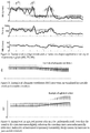
- An embodiment of the invention implements a smoothing average over a two-minute window. This smoothed data is then displayed as the trend over time.
- the middle panel in figure 1 shows an example of the smoothed trend line overlaid on the dataset.
- the method adds a visual indication of variability to the graph.
- the visual indication of variability preferably consists of an envelope which overlays the smoothed trend.
- the visualization updates in real-time for monitored parameters, but may be applied retroactively on historical data.
- the minimum and maximum points within each window are determined and stored in an array of peaks. Preferably once the minimum and maximum points are determined in each window position, all the peaks are plotted on the graph.
- the maximum peaks are preferably then connected by line segments, with points between the peaks being interpolated.
- the minimum points are also preferably connected by line segments with points between the minimum peaks being interpolated.
- the bottom panel in Figure 1 is an example of this envelope. In this embodiment, the area within the maximum envelope and the minimum envelope may be shaded.
- a quantitative coefficient of variability is preferably calculated for each point on the chart and displayed.
- the coefficient of variability is preferably calculated from a window of data points which is smaller than the total number of points on the graph.
- the coefficient of variability is preferably based on the statistics of the dataset calculated within the window.
- the coefficient of variability is preferably a function of statistical variance, standard deviation, or entropy.
- error bars are applied behind the smoothed dataset.
- the error bars are preferably a function of the standard deviation of the dataset within a window of, for example, 2 minutes.
- the error bar is preferably overlaid on the graph at the last point in the window, the center point in the window, or the first point in the window.
- a function of one or more fractal scaling coefficients, or a function of a ratio of at least two fractal scaling coefficients is utilized and overlaid on the graph.
- a set of fractal scaling coefficients is calculated for the entire dataset (FC1), then again for the window (FC2).
- the coefficient of variability is preferably calculated as a function of one or more coefficients from the set of FC1 as compared to FC2.
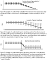
- One embodiment of the visualization is to display variability as a function of the difference or absolute value of the difference of two or more smoothing algorithms applied to the dataset.
- two moving average algorithms are applied to the dataset, one with a window of ten (10) minutes and one with a window of two (2) minutes.
- the visualization preferably consists of a graph of the two moving averages overlaid on each other, or both overlaid on the dataset, smoothed or un-smoothed. This may enable the caregiver to see the trend from the smoothed data as well as discern the absolute difference between the smoothed data trends. It is understood that when the two averages cross, i.e. the absolute difference between the two averages reaches zero, the trend in the data has changed direction. This can predict a rapid change in state and trigger an alarm signal.
- the difference between the results of the two smoothing algorithms is calculated and displayed on a graph.
- the graph is overlaid on the graph of the smoothed dataset, or appears in its own space.
- This visualization preferably provides an indicator of the momentum behind a trend, where a large difference between the results indicates a strong trend, and a small difference between the results indicates a stable trend. However, a change in sign indicates a reversal of the previous trend.
- the stochastic plot may be overlaid on the raw dataset or a smoothed dataset.
- the stochastic plot can be interpreted by a care provider to predict a patient's future status.
- the visualization including a smoothing component and an indication of variability is applied to one or more datasets relating to the respiratory system.
- the user can interpret the visualization in order to assess or predict patient state, health state, respiratory status, disease state or response to a medical intervention.
- the user may also use the visualization of variability to diagnose a disease.
- the user may draw conclusions from the visualization including, an assessment of the patient's response to an opioid, a diagnosis or prediction of respiratory arrest, respiratory failure, apnea or cardiac arrest.
- the user may assess the patient's respiratory sufficiency, likelihood of successful extubation or the necessity of intubation.
- Figure 3 illustrates an example of the display of the visualization algorithm on a minute ventilation dataset.
- the patient in the example maintains a similar minute ventilation and minute ventilation variability over time.
- a caregiver could draw the conclusion that the patient has a good status, free of various disease states.
- Figure 11 shows an example of a healthy response to an opioid dose, with only a slightly downward trend on the MV dataset, and little change in the signal variability. This type of response would lead a caregiver to conclude that the patient is correctly dosed.
- Figure 4 indicates an example of an agitated patient.
- the increase in MV variability and MV trend as shown in the visualization could lead a caregiver to conclude that the patient is undermedicated and could adjust the patient's dose of pain medication accordingly.
- Figure 9 is an example of a patient who responds idiosyncratically to an opioid dose. The variability increases, which could indicate restlessness and discomfort and general inefficacy of the pain medication.
- FIG 5 is a case in which a caregiver could use the visualization to diagnose respiratory compromise and undertake a medical intervention to prevent patient state from worsening. Interventions could include waking the patient, administering an opoid antagonist such as Naloxone, or intubating and ventilating the patient.
- Figure 8 is an example of the visualization applied to an MV dataset in a patient suffering respiratory compromise as a result of a dose of an opioid.
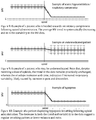
- Apnea is a state in which the breathing is interrupted. It may result from a variety of causes, including opioid toxicity. The sooner opiate toxicity can be identified, the sooner a caregiver can undertake measures to prevent the patient's condition from worsening. Periods of apnea are generally followed by a period of rescue breathing which may include larger than normal or faster than normal breaths, which normalize over time. The difference between the breaths during these periods translates to a high index of variability in datasets related to the respiratory system. Apnea can be identified by a downward trend in minute volume, a high variability in respiratory rate, or interbreath interval, and a high variability in tidal volume and minute ventilation.
- Figure 6 shows an example of the increased variability and decrease in trend in minute ventilation to indicate the onset of apnea.
- Figure 7 shows an example of the onset of apnea as a symptom of opioid toxicity in response to a dose of opioid pain medication.
- Figure 10 shows an example of the visualization on the MV dataset in a patient suffering hypopnea, or shallow breathing.
- it is difficult to differentiate hypopnea from apnea however, the variability in each case is very different.
- the variability in the hypopneic patient's dataset is much lower, which allows a caregiver to differentiate between the two cases.
- the methods disclosed herein may also be applied to parameters associated with the circulatory system including measurements of the heart rate, or its inverse, beat-to-beat interval.
- Low variability in the heart rate can predict or, indicate, or quantify the progression of many conditions including myocardial infarction, congestive heart failure, diabetic neuropathy, depression or susceptibility to SIDS.
- the envelope provides a visualization of heart rate variability to assist the caregiver in identifying, or assessing the risk of the aforementioned conditions.
- Figure 13 depicts a preferred embodiment of a patient monitoring system 1300 adapted to calculated and display a physiological parameter's trend and variability as well as their evolution over time.
- patient monitoring system 1300 is a portable device that can be mounted on an IV pole, attached to a bed, attached to a wall, placed on a surface or otherwise positioned.
- Patient monitoring system 1300 may be adapted for use during medical procedures, recovery, and/or for patient monitoring.
- patient monitoring system 1300 is battery powered and/or has a power cable.
- Patient monitoring system 1300 preferably has at least one input port 1305.
- each input port 1305 is adapted to receive signals from one or more sensors remote to patient monitoring system 1300.
- patient monitoring system 1300 may further include wireless communication technology to receive signals from remote and wireless sensors.
- the sensors may be adapted to monitor for a specific patient characteristic or multiple characteristics.
- Patient monitoring system 1300 preferably is adapted to evaluate the data received from the sensors and apply the algorithms described herein to the data.
- the patient monitoring system 1300 may be able to receive custom algorithms and evaluate the data using the custom algorithm.
- Patient monitoring system 1300 further includes a screen or display device 1310.
- screen 1310 is capable of displaying information about patient monitoring system 1300 and the patient being monitored.
- Screen 1310 preferably displays at least one graph or window of the patient's condition, as described herein.
- Each graph may be a fixed size or adjustable.
- the graph may be customizable based on the number of data points, a desired length and/or time of measurement, or a certain number of features (i.e. breaths, breath pauses, or obstructed breaths).
- the scale of the graph may be adjustable.
- the patient or caregiver may be able to choose what is displayed on screen 1310.
- screen 1310 may be able to display the mean, median, and/or standard deviation of data being monitored; the max, min and or range of data being monitored; an adaptive algorithm based on trend history; a adapted algorithm based on large populations of like patients (i.e. condition, age, weight, and events); and/or patent breathing parameters (i.e. blood pressure, respiratory rate, CO 2 , and/or O 2 rates).
- Patient monitoring system 1300 is equipped with an alarm.
- the alarm can be an audio alarm and/or a visual alarm.
- the alarm may trigger based on certain conditions being met. For example, based on trends, real-time conditions, or patient parameter variability.
- the alarm may be customizable, both in sound/visualization and in purpose.
- the patient and/or caregiver may be able to navigate through multiple windows that display different information. For example, certain windows may display the graphs described herein, certain windows may display the patient's biographical data, and certain windows may display the system's status. Additionally, custom windows may be added (e.g by the patient, caregiver, or by the system automatically). For example, a custom window may be for clinical use, to mark events, or to display the patient's condition.
- patient monitoring system 1300 has a plurality of configurations.
- the configurations are preferably adapted to display relevant information to a caregiver or patient about the patient based on the patient's current condition. For example, for a patient undergoing a surgery, the nurse or doctor may need different information than for a patient recovering from an illness.
- the patient monitoring system 1300 allows the patient or caregiver to select a configuration.
- Selectable configurations may include, but are not limited to specific procedures, specific illnesses, specific afflictions, specific patient statuses, specific patient conditions, general procedures, general illnesses, general afflictions, general patient statuses, and/or general patient conditions.
- the patient monitoring system 1300 Upon selection, preferably, the patient monitoring system 1300 will automatically display data relevant to the selection. In another embodiment, the patient monitoring system 1300 may automatically determine an appropriate configuration based on the data received from the patient. The patient or caregiver may be able to customize configurations once they are chosen.
- an exemplary system includes at least computing device 1200, for example contained within the system depicted in figure 13 , including a processing unit (CPU) 1220 and a system bus 1210 that couples various system components including the system memory such as read only memory (ROM) 1240 and random access memory (RAM) 1250 to the processing unit 1220.
- system memory 1230 may be available for use as well.
- the system bus 1210 may be any of several types of bus structures including a memory bus or memory controller, a peripheral bus, and a local bus using any of a variety of bus architectures.
- a basic input/output (BIOS) stored in ROM 1240 or the like may provide the basic routine that helps to transfer information between elements within the computing device 1200, such as during start-up.
- the computing device 1200 further includes storage devices such as a hard disk drive 1260, a magnetic disk drive, an optical disk drive, tape drive or the like.
- the storage device 1260 is connected to the system bus 1210 by a drive interface.
- the drives and the associated computer readable media provide nonvolatile storage of computer readable instructions, data structures, program modules and other data for the computing device 1200.
- the basic components are known to those of skill in the art and appropriate variations are contemplated depending on the type of device, such as whether the device is a small, handheld computing device, a desktop computer, a computer server, a handheld scanning device, or a wireless devices, including wireless Personal Digital Assistants ("PDAs"), tablet devices, wireless web-enabled or “smart” phones (e.g., Research in Motion's BlackberryTM, an AndroidTM device, Apple's iPhoneTM), other wireless phones, a game console (e.g, a Playstation TM, an XboxTM, or a WiiTM), a Smart TV, a wearable internet connected device, etc.
- PDAs Personal Digital Assistants
- tablet devices wireless web-enabled or "smart” phones (e.g., Research in Motion's BlackberryTM, an AndroidTM device, Apple's iPhoneTM), other wireless phones, a game console (e.g, a Playstation TM, an XboxTM, or a WiiTM), a Smart TV, a wearable
- an input device 1290 represents any number of input mechanisms, such as a microphone for speech, a touch-sensitive screen for gesture or graphical input, keyboard, mouse, motion input, speech, game console controller, TV remote and so forth.
- the output device 1270 can be one or more of a number of output mechanisms known to those of skill in the art, for example, printers, monitors, projectors, speakers, and plotters.
- the output can be via a network interface, for example uploading to a website, emailing, attached to or placed within other electronic files, and sending an SMS or MMS message.
- multimodal systems enable a user to provide multiple types of input to communicate with the computing device 1200.
- the communications interface 1280 generally governs and manages the user input and system output. There is no restriction on the invention operating on any particular hardware arrangement and therefore the basic features here may easily be substituted for improved hardware or firmware arrangements as they are developed.
- the illustrative system embodiment is presented as comprising individual functional blocks (including functional blocks labeled as a "processor").
- the functions these blocks represent may be provided through the use of either shared or dedicated hardware, including, but not limited to, hardware capable of executing software.
- the functions of one or more processors presented in figure 12 may be provided by a single shared processor or multiple processors.
- Illustrative embodiments may comprise microprocessor and/or digital signal processor (DSP) hardware, read-only memory (ROM) for storing software performing the operations discussed below, and random access memory (RAM) for storing results.
- DSP digital signal processor
- ROM read-only memory
- RAM random access memory
- VLSI Very large scale integration
- Embodiments within the scope of the present invention may also include computer-readable media for carrying or having computer-executable instructions or data structures stored thereon.
- Such computer-readable media can be any available media that can be accessed by a general purpose or special purpose computer.
- Such computer-readable media can comprise RAM, ROM, EEPROM, CD-ROM or other optical disk storage, magnetic disk storage or other magnetic storage devices, or any other medium which can be used to carry or store desired program code means in the form of computer-executable instructions or data structures.
- a network or another communications connection either hardwired, wireless, or combination thereof
- any such connection is properly termed a computer-readable medium. Combinations of the above should also be included within the scope of the computer-readable media.
- Computer-executable instructions include, for example, instructions and data which cause a general purpose computer, special purpose computer, or special purpose processing device to perform a certain function or group of functions.
- Computer-executable instructions also include program modules that are executed by computers in stand-alone or network environments.
- program modules include routines, programs, objects, components, and data structures, etc. that perform particular tasks or implement particular abstract data types.
- Computer-executable instructions, associated data structures, and program modules represent examples of the program code means for executing steps of the methods disclosed herein. The particular sequence of such executable instructions or associated data structures represents examples of corresponding acts for implementing the functions described in such steps.
- Networks may include the Internet, one or more Local Area Networks ("LANs"), one or more Metropolitan Area Networks ("MANs”), one or more Wide Area Networks ("WANs”), one or more Intranets, etc.
- LANs Local Area Networks
- MANs Metropolitan Area Networks
- WANs Wide Area Networks
- Intranets etc.
- Embodiments may also be practiced in distributed computing environments where tasks are performed by local and remote processing devices that are linked (either by hardwired links, wireless links, or by a combination thereof) through a communications network, e.g. in the "cloud.”
- program modules may be located in both local and remote memory storage devices.
Landscapes
- Engineering & Computer Science (AREA)
- Health & Medical Sciences (AREA)
- General Health & Medical Sciences (AREA)
- Medical Informatics (AREA)
- Primary Health Care (AREA)
- Public Health (AREA)
- Epidemiology (AREA)
- Biomedical Technology (AREA)
- Business, Economics & Management (AREA)
- General Business, Economics & Management (AREA)
- Physics & Mathematics (AREA)
- Life Sciences & Earth Sciences (AREA)
- Theoretical Computer Science (AREA)
- Bioinformatics & Cheminformatics (AREA)
- Data Mining & Analysis (AREA)
- Bioinformatics & Computational Biology (AREA)
- Biotechnology (AREA)
- Evolutionary Biology (AREA)
- Spectroscopy & Molecular Physics (AREA)
- Biophysics (AREA)
- Measuring And Recording Apparatus For Diagnosis (AREA)
- General Physics & Mathematics (AREA)
- Measurement Of The Respiration, Hearing Ability, Form, And Blood Characteristics Of Living Organisms (AREA)
- Measurement And Recording Of Electrical Phenomena And Electrical Characteristics Of The Living Body (AREA)
- Tourism & Hospitality (AREA)
- Child & Adolescent Psychology (AREA)
- Economics (AREA)
- Human Resources & Organizations (AREA)
- Marketing (AREA)
- Strategic Management (AREA)
Claims (12)
- System für Anzeige von Trends und Variabilität in einem physiologischen Datensatz, umfassend:eine Patientenüberwachungsvorrichtung (1300);mindestens einen Sensor, der mit der Patientenüberwachungsvorrichtung verbunden ist;einen Prozessor, der innerhalb der Patientenüberwachungsvorrichtung enthalten ist und Patientendaten von dem mindestens einen Sensor empfängt;einen Bildschirm (1310), der innerhalb der Patientenüberwachungsvorrichtung enthalten ist und Anzeigeinformationen von dem Prozessor empfängt; undmindestens einen von einem akustischen oder visuellen Alarm, wobei der Alarm ausgelöst wird, nachdem eine vorbestimmte Bedingung in Bezug auf die Variabilität oder den Trend des physiologischen Datensatzes erfüllt ist, wobei die vorbestimmte Bedingung auf mindestens einem von folgenden basiert:(1) Unterschied zwischen Maximum und Minimum innerhalb eines Zeitfensters,(2) dem Wert des Trends innerhalb eines Zeitfensters, und(3) Bereich innerhalb der maximalen Hülle und der minimalen Hülle,wobei der Prozessor:den physiologischen Datensatz von dem mindestens einen Sensor erhält;einen Glättungsalgorithmus auf den physiologischen Datensatz anwendet, um einen Trend des physiologischen Datensatzes zu erhalten;einen Variabilitätsalgorithmus auf den physiologischen Datensatz anwendet, um die Variabilität des physiologischen Datensatzes zu erhalten;einen Echtzeitgraphen des Trends des physiologischen Datensatzes auf dem Bildschirm ausgibt; undeinen Echtzeitgraphen der Variabilität des physiologischen Datensatzes auf dem Bildschirm, auf dem Graphen des Trends des physiologischen Datensatzes überlagert, ausgibt, wobei der Graph der Variabilität des physiologischen Datensatzes eine visuelle Hülle in Echtzeit umfasst, die oben durch einen Plot der von dem Variabilitätsalgorithmus identifizierten Maxima begrenzt ist und unten durch einen Plot der von dem Variabilitätsalgorithmus identifizierten Minima begrenzt ist, wobei die Maxima und Minima innerhalb jedes Zeitfensters, über das die Variabilität geschätzt wird, identifiziert werden.
- System nach Anspruch 1, wobei die Größenordnung der Variabilität, die von dem Graphen der Variabilität des physiologischen Datensatzes angezeigt wird, als Funktion von mindestens einem des rohen Datensatzes, des geglätteten Datensatzes, mehrerer geglätteter Datensätze, der fraktalen Skalierungskoeffizienten des Datensatzes oder der stochastischen Koeffizienten des Datensatzes berechnet wird.
- Verfahren zum Anzeigen von Trends und Variabilität in einem physiologischen Datensatz, umfassend, auf einem Prozessor:Erhalten des physiologischen Datensatzes;Anwenden eines Glättungsalgorithmus auf den physiologischen Datensatz, um einen Trend des physiologischen Datensatzes zu erhalten;Anwenden eines Variabilitätsalgorithmus auf den physiologischen Datensatz, um die Variabilität des physiologischen Datensatzes zu erhalten;Ausgeben eines Echtzeitgraphen des Trends des physiologischen Datensatzes;Ausgeben eines Echtzeitgraphen der Variabilität des physiologischen Datensatzes, der auf dem Graphen des Trends des physiologischen Datensatzes überlagert ist, wobei der Graph der Variabilität des physiologischen Datensatzes eine visuelle Hülle in Echtzeit umfasst, die oben durch einen Plot der von dem Variabilitätsalgorithmus identifizierten Maxima begrenzt ist und unten durch einen Plot der von dem Variabilitätsalgorithmus identifizierten Minima begrenzt ist, wobei die Maxima und Minima innerhalb jedes Zeitfensters, über das die Variabilität geschätzt wird, identifiziert werden;Auslösen mindestens eines von einem akustischen oder visuellen Alarm, nachdem eine vorbestimmte Bedingung in Bezug auf die Variabilität oder den Trend des physiologischen Datensatzes erfüllt ist, wobei die vorbestimmte Bedingung auf mindestens einem von folgenden basiert:(1) Unterschied zwischen Maximum und Minimum innerhalb eines Zeitfensters,(2) dem Wert des Trends innerhalb eines Zeitfensters, und(3) Bereich innerhalb der maximalen Hülle und der minimalen Hülle.
- System nach Anspruch 1 oder Verfahren nach Anspruch 3, wobei der physiologische Datensatz auf Daten basiert, die aus dem Respirationssystem eines Patienten erhalten werden.
- System nach Anspruch 1 oder Verfahren nach Anspruch 3, wobei der Glättungsalgorithmus einer von einem gleitenden Mittelwertalgorithmus und einem digitalen Filteralgorithmus ist.
- System nach Anspruch 1 oder Verfahren nach Anspruch 3, wobei der Graph des Trends des physiologischen Datensatzes und der Graph der Variabilität des physiologischen Datensatzes nebeneinander graphisch dargestellt sind.
- System nach Anspruch 1 oder Verfahren nach Anspruch 3, wobei der Raum zwischen den Begrenzungen schattiert ist.
- System nach Anspruch 1 oder Verfahren nach Anspruch 3, wobei es sich bei dem physiologischen Datensatz um Intervalldaten zwischen Atemzügen handelt.
- System nach Anspruch 1 oder Verfahren nach Anspruch 3, wobei der Graph der Variabilität des physiologischen Datensatzes eine Funktion von fraktalen Skalierungskoeffizienten ist, die zu verschiedenen Zeitpunkten und über verschiedene Zeitfenster des Datensatzes berechnet werden.
- System nach Anspruch 1 oder Verfahren nach Anspruch 3, wobei der Graph der Variabilität des physiologischen Datensatzes eines oder mehrere von Fehlerbalken, Liniendiagrammen, Momentbalken, schattierten Bereichen unter einer Kurve und einem stochastischen Plot umfasst.
- System nach Anspruch 1 oder Verfahren nach Anspruch 3, wobei die Größenordnung der Variabilität, die von dem Graphen der Variabilität des physiologischen Datensatzes angezeigt wird, als Funktion von mindestens einem des rohen Datensatzes, des geglätteten Datensatzes, mehrerer geglätteter Datensätze, der fraktalen Skalierungskoeffizienten des Datensatzes oder der stochastischen Koeffizienten des Datensatzes berechnet wird.
- System nach Anspruch 1, wobei der Sensor ein transthorakales Impedanzmessgerät zum Erhalten eines physiologischen Datensatzes umfasst.
Applications Claiming Priority (2)
| Application Number | Priority Date | Filing Date | Title |
|---|---|---|---|
| US201461948964P | 2014-03-06 | 2014-03-06 | |
| PCT/US2015/019196 WO2015134880A1 (en) | 2014-03-06 | 2015-03-06 | Methods and devices for displaying trend and variability in a physiological dataset |
Publications (3)
| Publication Number | Publication Date |
|---|---|
| EP3114672A1 EP3114672A1 (de) | 2017-01-11 |
| EP3114672A4 EP3114672A4 (de) | 2017-11-08 |
| EP3114672B1 true EP3114672B1 (de) | 2020-06-24 |
Family
ID=54017875
Family Applications (1)
| Application Number | Title | Priority Date | Filing Date |
|---|---|---|---|
| EP15758061.4A Active EP3114672B1 (de) | 2014-03-06 | 2015-03-06 | Verfahren und vorrichtungen für anzeige von trend und variabilität in einem physiologischen datensatz |
Country Status (13)
| Country | Link |
|---|---|
| US (3) | US9595123B2 (de) |
| EP (1) | EP3114672B1 (de) |
| JP (1) | JP6557673B2 (de) |
| KR (1) | KR20160132332A (de) |
| CN (1) | CN106415695B (de) |
| AU (1) | AU2015226963B2 (de) |
| CA (1) | CA2941698A1 (de) |
| CL (1) | CL2016002243A1 (de) |
| ES (1) | ES2827309T3 (de) |
| IL (1) | IL247611B (de) |
| MX (1) | MX2016011547A (de) |
| WO (1) | WO2015134880A1 (de) |
| ZA (1) | ZA201606267B (de) |
Families Citing this family (20)
| Publication number | Priority date | Publication date | Assignee | Title |
|---|---|---|---|---|
| EP3114672B1 (de) * | 2014-03-06 | 2020-06-24 | Respiratory Motion, Inc. | Verfahren und vorrichtungen für anzeige von trend und variabilität in einem physiologischen datensatz |
| JP6848656B2 (ja) * | 2017-04-28 | 2021-03-24 | 横河電機株式会社 | 表示装置、表示方法及びプログラム |
| CN110019367B (zh) * | 2017-12-28 | 2022-04-12 | 北京京东尚科信息技术有限公司 | 一种统计数据特征的方法和装置 |
| CN109077712A (zh) * | 2018-06-25 | 2018-12-25 | 深圳市德力凯医疗设备股份有限公司 | 一种脑血流的血流变化幅度的显示方法及系统 |
| US11213225B2 (en) | 2018-08-20 | 2022-01-04 | Thomas Jefferson University | Acoustic sensor and ventilation monitoring system |
| EP4566543A3 (de) | 2018-08-20 | 2025-08-20 | Thomas Jefferson University | Akustischer sensor und beatmungsüberwachungssystem |
| US11000191B2 (en) | 2018-08-20 | 2021-05-11 | Thomas Jefferson University | Acoustic sensor and ventilation monitoring system |
| CN109925597B (zh) * | 2019-02-01 | 2023-06-09 | 广州唯思冠电子科技有限公司 | 一种基于衡通仪的细胞呈现方法 |
| CN109920546A (zh) * | 2019-02-01 | 2019-06-21 | 广州豫本草电子科技有限公司 | 一种基于衡通仪的数据处理方法 |
| CN110413949B (zh) * | 2019-08-02 | 2021-03-09 | 湖南联智科技股份有限公司 | 一种呈递增或递减变化趋势的数据处理方法 |
| US10891766B1 (en) | 2019-09-04 | 2021-01-12 | Google Llc | Artistic representation of digital data |
| JP7419904B2 (ja) * | 2020-03-18 | 2024-01-23 | 株式会社リコー | 生体モニタ装置、生体モニタ方法及びプログラム |
| US12230406B2 (en) | 2020-07-13 | 2025-02-18 | Vignet Incorporated | Increasing diversity and engagement in clinical trails through digital tools for health data collection |
| US12211594B1 (en) | 2021-02-25 | 2025-01-28 | Vignet Incorporated | Machine learning to predict patient engagement and retention in clinical trials and increase compliance with study aims |
| US11296971B1 (en) | 2021-02-03 | 2022-04-05 | Vignet Incorporated | Managing and adapting monitoring programs |
| US11196656B1 (en) | 2021-02-03 | 2021-12-07 | Vignet Incorporated | Improving diversity in cohorts for health research |
| US11789837B1 (en) * | 2021-02-03 | 2023-10-17 | Vignet Incorporated | Adaptive data collection in clinical trials to increase the likelihood of on-time completion of a trial |
| US11361846B1 (en) | 2021-02-03 | 2022-06-14 | Vignet Incorporated | Systems and methods for customizing monitoring programs involving remote devices |
| US12248383B1 (en) | 2021-02-25 | 2025-03-11 | Vignet Incorporated | Digital systems for managing health data collection in decentralized clinical trials |
| US12248384B1 (en) | 2021-02-25 | 2025-03-11 | Vignet Incorporated | Accelerated clinical trials using patient-centered, adaptive digital health tools |
Family Cites Families (105)
| Publication number | Priority date | Publication date | Assignee | Title |
|---|---|---|---|---|
| US3433217A (en) | 1965-09-30 | 1969-03-18 | Gen Electric | Respiration monitor |
| BE757682A (fr) | 1969-10-23 | 1971-04-01 | Ieram Sarl | Dispositif de rheoplethysmographie |
| US3690143A (en) | 1970-11-27 | 1972-09-12 | American Optical Corp | Self calibrating tidal volume impedance pneumograph |
| JPS51114156A (en) | 1975-03-31 | 1976-10-07 | Toshiba Corp | Device for detecting the amount of ventilation |
| CN1034665A (zh) | 1988-01-08 | 1989-08-16 | 北京航空学院 | 心脏功能自动无创检测仪 |
| US5058583A (en) | 1990-07-13 | 1991-10-22 | Geddes Leslie A | Multiple monopolar system and method of measuring stroke volume of the heart |
| US5251126A (en) * | 1990-10-29 | 1993-10-05 | Miles Inc. | Diabetes data analysis and interpretation method |
| US5735284A (en) | 1992-06-24 | 1998-04-07 | N.I. Medical Ltd. | Method and system for non-invasive determination of the main cardiorespiratory parameters of the human body |
| IL102300A (en) | 1992-06-24 | 1996-07-23 | N I Medical Ltd | Non-invasive system for determining of the main cardiorespiratory parameters of the human body |
| JP3453877B2 (ja) * | 1994-11-11 | 2003-10-06 | 松下電器産業株式会社 | 睡眠健康管理システム |
| US6168568B1 (en) | 1996-10-04 | 2001-01-02 | Karmel Medical Acoustic Technologies Ltd. | Phonopneumograph system |
| US5951611A (en) * | 1996-11-18 | 1999-09-14 | General Electric Company | Diagnostic trend analysis |
| US6809462B2 (en) | 2000-04-05 | 2004-10-26 | Sri International | Electroactive polymer sensors |
| US5953441A (en) | 1997-05-16 | 1999-09-14 | Harris Corporation | Fingerprint sensor having spoof reduction features and related methods |
| JP2000060803A (ja) * | 1998-08-21 | 2000-02-29 | Terumo Corp | 血糖値情報処理システム |
| SE9802827D0 (sv) | 1998-08-25 | 1998-08-25 | Siemens Elema Ab | Ventilator |
| US6980679B2 (en) * | 1998-10-23 | 2005-12-27 | Varian Medical System Technologies, Inc. | Method and system for monitoring breathing activity of a subject |
| DE19857090A1 (de) | 1998-12-10 | 2000-06-29 | Stephan Boehm | Verfahren zur regionalen Bestimmung des alveolären Öffnens und des alveolären Schließens der Lunge |
| US6402697B1 (en) | 1999-01-21 | 2002-06-11 | Metasensors, Inc. | Non-invasive cardiac output and pulmonary function monitoring using respired gas analysis techniques and physiological modeling |
| US6173198B1 (en) | 1999-01-29 | 2001-01-09 | Baxter International Inc. | Apparatus and method for the accurate placement of biomedical sensors |
| US6366803B1 (en) | 1999-12-23 | 2002-04-02 | Agere Systems Guardian Corp. | Predictive probe stabilization relative to subject movement |
| US6286806B1 (en) | 2000-01-20 | 2001-09-11 | Dan E. Corcoran | Adjustable sensor supporting apparatus and method |
| US6408259B1 (en) * | 2000-02-01 | 2002-06-18 | General Electric Company | Alert generation for trend performance analysis |
| US20060070623A1 (en) | 2000-04-20 | 2006-04-06 | Wilkinson Malcolm H | Method and apparatus for determining a bodily characteristic or condition |
| US6821254B2 (en) * | 2000-07-21 | 2004-11-23 | Institute Of Critical Care Medicine | Cardiac/respiratory arrest detector |
| US6402969B1 (en) | 2000-08-15 | 2002-06-11 | Sandia Corporation | Surface—micromachined rotatable member having a low-contact-area hub |
| US8548576B2 (en) * | 2000-12-15 | 2013-10-01 | Cardiac Pacemakers, Inc. | System and method for correlation of patient health information and implant device data |
| US20050090753A1 (en) | 2001-04-02 | 2005-04-28 | Daniel Goor | Device for determining hemodynamic state |
| FR2823660A1 (fr) * | 2001-04-18 | 2002-10-25 | Pneumopartners | Dispositif d'aide a l'analyse de bruits adventices |
| US6731985B2 (en) | 2001-10-16 | 2004-05-04 | Pacesetter, Inc. | Implantable cardiac stimulation system and method for automatic capture verification calibration |
| US7069263B1 (en) * | 2002-02-19 | 2006-06-27 | Oracle International Corporation | Automatic trend analysis data capture |
| US7096061B2 (en) * | 2002-07-03 | 2006-08-22 | Tel-Aviv University Future Technology Development L.P. | Apparatus for monitoring CHF patients using bio-impedance technique |
| AU2003262625A1 (en) | 2002-08-01 | 2004-02-23 | California Institute Of Technology | Remote-sensing method and device |
| DE10238310A1 (de) | 2002-08-21 | 2004-03-04 | Erich Jaeger Gmbh | Elektrodenanordnung |
| US6976963B2 (en) * | 2002-09-30 | 2005-12-20 | Clift Vaughan L | Apparatus and method for precision vital signs determination |
| US6827695B2 (en) | 2002-10-25 | 2004-12-07 | Revivant Corporation | Method of determining depth of compressions during cardio-pulmonary resuscitation |
| US8002553B2 (en) * | 2003-08-18 | 2011-08-23 | Cardiac Pacemakers, Inc. | Sleep quality data collection and evaluation |
| JP4750032B2 (ja) * | 2003-08-18 | 2011-08-17 | カーディアック ペースメイカーズ, インコーポレイテッド | 医療用装置 |
| EP2008581B1 (de) | 2003-08-18 | 2011-08-17 | Cardiac Pacemakers, Inc. | Patientenüberwachungs-, Diagnose- und/oder Therapiesysteme und -verfahren |
| US7367953B2 (en) | 2003-11-26 | 2008-05-06 | Ge Medical Systems Global Technology Company | Method and system for determining a period of interest using multiple inputs |
| US7231244B2 (en) * | 2003-12-18 | 2007-06-12 | Ge Healthcare Finland Oy | Method and arrangement for predicting perioperative myocardial ischemia |
| US7187966B2 (en) * | 2004-04-15 | 2007-03-06 | Ge Medical Systems Information Technologies, Inc. | Method and apparatus for displaying alternans data |
| ES2346453T3 (es) | 2004-07-15 | 2010-10-15 | Laerdal Medical As | Metodo y sistema para monitorizar ventilaciones. |
| US7361146B1 (en) * | 2004-11-24 | 2008-04-22 | Pacesetter, Inc. | System and method for detecting abnormal respiration via respiratory parameters derived from intracardiac electrogram signals |
| EP1836576B1 (de) * | 2004-12-17 | 2012-02-01 | Korea Research Institute of Standards and Science | Präzisions-diagnoseverfahren für ausfallschutz und prädiktive wartung einer unterdruckpumpe und präzisions-diagnosesystem dafür |
| US7196317B1 (en) | 2005-03-25 | 2007-03-27 | Virginia Tech Intellectual Properties, Inc. | System, device, and method for detecting perturbations |
| US7785262B2 (en) * | 2005-04-25 | 2010-08-31 | University Of Florida Research Foundation, Inc. | Method and apparatus for diagnosing respiratory disorders and determining the degree of exacerbations |
| US7603170B2 (en) * | 2005-04-26 | 2009-10-13 | Cardiac Pacemakers, Inc. | Calibration of impedance monitoring of respiratory volumes using thoracic D.C. impedance |
| US8641637B2 (en) * | 2005-06-10 | 2014-02-04 | Telethon Institute For Child Health Research | Method of measuring an acoustic impedance of a respiratory system and diagnosing a respiratory disease or disorder or monitoring treatment of same |
| US20090149748A1 (en) | 2005-08-25 | 2009-06-11 | Virginia Commonwealth University | Portable Pulmonary Injury diagnostic Devices And Methods |
| CN101300262A (zh) | 2005-11-02 | 2008-11-05 | 弗·哈夫曼-拉罗切有限公司 | 二齿c,p手性膦配体 |
| US7766840B2 (en) | 2005-12-01 | 2010-08-03 | Cardiac Pacemakers, Inc. | Method and system for heart failure status evaluation based on a disordered breathing index |
| DE102006004415A1 (de) | 2006-01-31 | 2007-08-09 | Up Management Gmbh & Co Med-Systems Kg | Vorrichtung zum Bewerten eines hämodynamischen Zustandes eines Patienten, wobei eine Herz-Lungen-Interaktion verwendet wird |
| US8306610B2 (en) * | 2006-04-18 | 2012-11-06 | Susan Mirow | Method and apparatus for analysis of psychiatric and physical conditions |
| WO2007131064A2 (en) * | 2006-05-02 | 2007-11-15 | Physiostream, Inc. | Collection and analysis of physiological data |
| US8010190B2 (en) | 2006-05-26 | 2011-08-30 | Cardiac Science Corporation | CPR feedback method and apparatus |
| US8979753B2 (en) * | 2006-05-31 | 2015-03-17 | University Of Rochester | Identifying risk of a medical event |
| WO2007147505A2 (en) | 2006-06-21 | 2007-12-27 | Universität Bern | A system for controlling administration of anaesthesia |
| KR101498305B1 (ko) | 2006-09-05 | 2015-03-03 | 엔. 아이. 메디컬 엘티디. | 심장 지표들의 비침습적 측정을 위한 방법 및 시스템 |
| EP2063761A2 (de) | 2006-09-05 | 2009-06-03 | N.I. MEDICAL Ltd. | Medizinisches instrument |
| US7764996B2 (en) * | 2006-10-31 | 2010-07-27 | Cardiac Pacemakers, Inc. | Monitoring of chronobiological rhythms for disease and drug management using one or more implantable device |
| US8032472B2 (en) * | 2007-04-04 | 2011-10-04 | Tuen Solutions Limited Liability Company | Intelligent agent for distributed services for mobile devices |
| US9943234B2 (en) | 2007-04-17 | 2018-04-17 | Cardiac Pacemakers, Inc. | Using respiration distress manifestations for heart failure detection |
| US7530956B2 (en) | 2007-06-15 | 2009-05-12 | Cardiac Pacemakers, Inc. | Daytime/nighttime respiration rate monitoring |
| US8034006B2 (en) | 2007-06-15 | 2011-10-11 | Board Of Regents, The University Of Texas System | Cardiopulmonary resuscitation sensor |
| EP2018825A1 (de) | 2007-07-26 | 2009-01-28 | Ecole Polytechnique Fédérale de Lausanne (EPFL) | Verfahren und Vorrichtung zur Quantifizierung von Mustern menschlicher physischer Aktivitäten |
| US8808193B2 (en) | 2007-09-11 | 2014-08-19 | Carefusion 207, Inc. | Regional oxygen uptake/perfusion measuring device and method |
| US20100324437A1 (en) | 2007-09-12 | 2010-12-23 | Freeman Jenny E | Device and method for assessing physiological parameters |
| US20090264789A1 (en) * | 2007-09-26 | 2009-10-22 | Medtronic, Inc. | Therapy program selection |
| US20090147006A1 (en) * | 2007-12-07 | 2009-06-11 | Roche Diagnostics Operations, Inc. | Method and system for event based data comparison |
| WO2009094335A1 (en) * | 2008-01-22 | 2009-07-30 | Cardiac Pacemakers, Inc. | Respiration as a trigger for therapy optimization |
| EP2249696B1 (de) | 2008-02-14 | 2017-06-07 | N.I. MEDICAL Ltd. | Verfahren und system zur verwendung bei der überwachung der linksventrikulären dysfunktion |
| JP5198162B2 (ja) | 2008-03-10 | 2013-05-15 | チェスト株式会社 | 呼吸インピーダンス測定装置及びその測定方法 |
| US20100152600A1 (en) * | 2008-04-03 | 2010-06-17 | Kai Sensors, Inc. | Non-contact physiologic motion sensors and methods for use |
| WO2009146214A1 (en) | 2008-04-18 | 2009-12-03 | Corventis, Inc. | Method and apparatus to measure bioelectric impedance of patient tissue |
| BRPI0907660A2 (pt) | 2008-05-01 | 2015-07-21 | 3M Innovative Properties Co | Sitema de sensor biomédico |
| US8660799B2 (en) | 2008-06-30 | 2014-02-25 | Nellcor Puritan Bennett Ireland | Processing and detecting baseline changes in signals |
| JP5219700B2 (ja) * | 2008-09-01 | 2013-06-26 | オムロンヘルスケア株式会社 | 生体指標管理装置 |
| JP5185049B2 (ja) * | 2008-09-29 | 2013-04-17 | テルモ株式会社 | 血糖値情報処理装置、血糖値情報処理方法及び血糖値情報処理プログラム |
| EP2348970A1 (de) | 2008-10-10 | 2011-08-03 | Regents of the University of Minnesota | Verbesserter monitor zur überwachung von herzinsuffizienz mittels bioimpedanz |
| NL2002225C2 (en) | 2008-11-19 | 2010-05-21 | Emergency Pulmonary Care B V | Apparatus and system for monitoring breathing or ventilation, defibrillator device, apparatus and system for monitoring chest compressions, valve apparatus. |
| US20100160740A1 (en) * | 2008-12-24 | 2010-06-24 | Gary Cohen | Use of Patterns in a Therapy Management System |
| US20100185225A1 (en) * | 2009-01-19 | 2010-07-22 | Albrecht Thomas E | Gui for an implantable distension device and a data logger |
| CN101496767B (zh) | 2009-02-27 | 2010-08-18 | 武汉依瑞德医疗设备新技术有限公司 | 胸外心脏按压节律提示器及其方法 |
| US8876742B2 (en) | 2009-03-06 | 2014-11-04 | Physio-Control, Inc. | Measurement of a compression parameter for CPR on a surface |
| EP2408521B1 (de) | 2009-03-17 | 2014-06-25 | Cardio Thrive, Inc | Externer defibrillator |
| US10588527B2 (en) * | 2009-04-16 | 2020-03-17 | Braemar Manufacturing, Llc | Cardiac arrhythmia report |
| JP2010272031A (ja) * | 2009-05-22 | 2010-12-02 | Univ Of Tsukuba | 携帯電話を用いた双方向的な生活習慣病管理支援システム |
| US8708905B2 (en) * | 2009-06-12 | 2014-04-29 | General Electric Company | Method, device and computer product for EEG monitoring, analysis and display |
| US8645165B2 (en) * | 2010-06-03 | 2014-02-04 | General Electric Company | Systems and methods for value-based decision support |
| CN103153184B (zh) * | 2010-08-13 | 2016-04-27 | 呼吸运动公司 | 用于通过呼吸量、运动和变化性的测量进行呼吸振动监视的设备和方法 |
| WO2012024401A2 (en) | 2010-08-17 | 2012-02-23 | University Of Florida Research Foundation, Inc. | Intelligent drug and/or fluid delivery system to optimizing medical treatment or therapy using pharmacodynamic and/or pharmacokinetic data |
| CN102650994A (zh) * | 2011-02-24 | 2012-08-29 | 悦康健康管理顾问科技股份有限公司 | 人体状况的整合管理系统及其管理方法 |
| US9413559B2 (en) * | 2011-06-03 | 2016-08-09 | Adobe Systems Incorporated | Predictive analysis of network analytics |
| US20130046197A1 (en) * | 2011-08-16 | 2013-02-21 | Daniel F. Dlugos, Jr. | Docking station for patient bedside monitoring units |
| US8830254B2 (en) | 2012-01-24 | 2014-09-09 | Ayasdi, Inc. | Systems and methods for graph rendering |
| US8782504B2 (en) * | 2012-04-11 | 2014-07-15 | Lsi Corporation | Trend-analysis scheme for reliably reading data values from memory |
| WO2013154783A1 (en) * | 2012-04-13 | 2013-10-17 | Medtronic, Inc. | Feedback-based diuretic or natriuretic molecule administration |
| CN103455699A (zh) * | 2012-05-31 | 2013-12-18 | 杨玉峰 | 自动生成个性化的生活方式干预方案的方法及系统 |
| KR101969945B1 (ko) | 2012-09-07 | 2019-04-17 | 레스퍼러토리 모션 인코포레이티드 | 전극 패드세트 |
| US9916416B2 (en) * | 2012-10-18 | 2018-03-13 | Virginia Tech Intellectual Properties, Inc. | System and method for genotyping using informed error profiles |
| CN203153714U (zh) * | 2013-03-21 | 2013-08-28 | 北京海利赢医疗科技有限公司 | 多参数动态记录分析装置 |
| CN103544397A (zh) * | 2013-10-30 | 2014-01-29 | 江苏万全科技有限公司 | 人体的生理健康指标数据进行汇总分析预警的方法 |
| JP6354144B2 (ja) * | 2013-12-10 | 2018-07-11 | Tdk株式会社 | 電子機器、方法及びプログラム |
| EP3114672B1 (de) * | 2014-03-06 | 2020-06-24 | Respiratory Motion, Inc. | Verfahren und vorrichtungen für anzeige von trend und variabilität in einem physiologischen datensatz |
-
2015
- 2015-03-06 EP EP15758061.4A patent/EP3114672B1/de active Active
- 2015-03-06 KR KR1020167027648A patent/KR20160132332A/ko not_active Withdrawn
- 2015-03-06 CA CA2941698A patent/CA2941698A1/en active Pending
- 2015-03-06 CN CN201580023046.8A patent/CN106415695B/zh active Active
- 2015-03-06 MX MX2016011547A patent/MX2016011547A/es unknown
- 2015-03-06 AU AU2015226963A patent/AU2015226963B2/en active Active
- 2015-03-06 JP JP2016555724A patent/JP6557673B2/ja active Active
- 2015-03-06 WO PCT/US2015/019196 patent/WO2015134880A1/en not_active Ceased
- 2015-03-06 ES ES15758061T patent/ES2827309T3/es active Active
- 2015-03-06 US US14/640,648 patent/US9595123B2/en active Active
-
2016
- 2016-09-04 IL IL247611A patent/IL247611B/en active IP Right Grant
- 2016-09-06 CL CL2016002243A patent/CL2016002243A1/es unknown
- 2016-09-09 ZA ZA2016/06267A patent/ZA201606267B/en unknown
-
2017
- 2017-03-09 US US15/454,500 patent/US10347020B2/en active Active
-
2019
- 2019-07-08 US US16/505,195 patent/US20190333257A1/en not_active Abandoned
Non-Patent Citations (1)
| Title |
|---|
| None * |
Also Published As
| Publication number | Publication date |
|---|---|
| AU2015226963B2 (en) | 2019-10-10 |
| US9595123B2 (en) | 2017-03-14 |
| WO2015134880A1 (en) | 2015-09-11 |
| US20190333257A1 (en) | 2019-10-31 |
| JP6557673B2 (ja) | 2019-08-07 |
| CL2016002243A1 (es) | 2017-03-24 |
| ES2827309T3 (es) | 2021-05-20 |
| CA2941698A1 (en) | 2015-09-11 |
| JP2017517286A (ja) | 2017-06-29 |
| CN106415695B (zh) | 2020-06-09 |
| CN106415695A (zh) | 2017-02-15 |
| ZA201606267B (en) | 2017-04-26 |
| EP3114672A1 (de) | 2017-01-11 |
| KR20160132332A (ko) | 2016-11-17 |
| US20170213368A1 (en) | 2017-07-27 |
| MX2016011547A (es) | 2017-08-08 |
| IL247611B (en) | 2019-01-31 |
| US10347020B2 (en) | 2019-07-09 |
| EP3114672A4 (de) | 2017-11-08 |
| US20150254880A1 (en) | 2015-09-10 |
| AU2015226963A1 (en) | 2016-09-22 |
Similar Documents
| Publication | Publication Date | Title |
|---|---|---|
| US10347020B2 (en) | Methods and devices for displaying trend and variability in a physiological dataset | |
| JP6370209B2 (ja) | 生体情報予測装置、生体情報予測方法、及びプログラム | |
| KR20190008991A (ko) | 내장된 알람 피로도 감소 특성을 이용한 지속적인 스트레스 측정 | |
| EP3490435B1 (de) | System zur überwachung physiologischer parameter | |
| US20180153476A1 (en) | Stroke detection using blood pressure surge | |
| WO2013016212A1 (en) | Hemodynamic reserve monitor and hemodialysis control | |
| WO2016061545A1 (en) | Assessing effectiveness of cpr | |
| CN109846470B (zh) | 异常判定装置、电子设备及计算机可读存储介质 | |
| JP6318047B2 (ja) | 疾病予測装置、及びプログラム | |
| CN113727643A (zh) | 通过地震感测的睡眠活动和身体生命体征进行非接触式监测 | |
| WO2017221937A1 (ja) | 生体情報測定支援装置、生体情報測定装置、生体情報測定支援方法、及び、生体情報測定支援プログラム | |
| JP7716818B2 (ja) | 中枢性無呼吸の検出 | |
| JP2022525844A (ja) | Qt補正のための装置及び方法 | |
| BR112016020662B1 (pt) | Métodos e dispositivos para exibir tendência e variabilidade em um conjunto de dados fisiológicos | |
| US20250281095A1 (en) | Method and apparatus for determining abnormal cardiac conditions non-invasively | |
| WO2025010429A1 (en) | Method and apparatus for evaluating cardiac function | |
| JP2025140564A (ja) | 推定装置及び推定方法 | |
| WO2021076396A1 (en) | Monitoring of breathing and heart function | |
| JP2018138170A (ja) | 疾病予測装置、及びプログラム |
Legal Events
| Date | Code | Title | Description |
|---|---|---|---|
| STAA | Information on the status of an ep patent application or granted ep patent |
Free format text: STATUS: THE INTERNATIONAL PUBLICATION HAS BEEN MADE |
|
| PUAI | Public reference made under article 153(3) epc to a published international application that has entered the european phase |
Free format text: ORIGINAL CODE: 0009012 |
|
| STAA | Information on the status of an ep patent application or granted ep patent |
Free format text: STATUS: REQUEST FOR EXAMINATION WAS MADE |
|
| 17P | Request for examination filed |
Effective date: 20160928 |
|
| AK | Designated contracting states |
Kind code of ref document: A1 Designated state(s): AL AT BE BG CH CY CZ DE DK EE ES FI FR GB GR HR HU IE IS IT LI LT LU LV MC MK MT NL NO PL PT RO RS SE SI SK SM TR |
|
| AX | Request for extension of the european patent |
Extension state: BA ME |
|
| DAV | Request for validation of the european patent (deleted) | ||
| DAX | Request for extension of the european patent (deleted) | ||
| A4 | Supplementary search report drawn up and despatched |
Effective date: 20171006 |
|
| RIC1 | Information provided on ipc code assigned before grant |
Ipc: G06T 11/60 20060101ALI20170929BHEP Ipc: G06F 19/00 20110101ALI20170929BHEP Ipc: G09B 23/28 20060101AFI20170929BHEP Ipc: G06T 11/20 20060101ALI20170929BHEP |
|
| STAA | Information on the status of an ep patent application or granted ep patent |
Free format text: STATUS: EXAMINATION IS IN PROGRESS |
|
| 17Q | First examination report despatched |
Effective date: 20190920 |
|
| REG | Reference to a national code |
Ref country code: DE Ref legal event code: R079 Ref document number: 602015054723 Country of ref document: DE Free format text: PREVIOUS MAIN CLASS: G09B0023280000 Ipc: G16H0010600000 |
|
| GRAP | Despatch of communication of intention to grant a patent |
Free format text: ORIGINAL CODE: EPIDOSNIGR1 |
|
| STAA | Information on the status of an ep patent application or granted ep patent |
Free format text: STATUS: GRANT OF PATENT IS INTENDED |
|
| RIC1 | Information provided on ipc code assigned before grant |
Ipc: G16H 40/63 20180101ALI20191111BHEP Ipc: G16H 50/20 20180101ALN20191111BHEP Ipc: G16H 10/60 20180101AFI20191111BHEP Ipc: G06T 11/20 20060101ALI20191111BHEP |
|
| INTG | Intention to grant announced |
Effective date: 20191128 |
|
| GRAS | Grant fee paid |
Free format text: ORIGINAL CODE: EPIDOSNIGR3 |
|
| GRAA | (expected) grant |
Free format text: ORIGINAL CODE: 0009210 |
|
| STAA | Information on the status of an ep patent application or granted ep patent |
Free format text: STATUS: THE PATENT HAS BEEN GRANTED |
|
| AK | Designated contracting states |
Kind code of ref document: B1 Designated state(s): AL AT BE BG CH CY CZ DE DK EE ES FI FR GB GR HR HU IE IS IT LI LT LU LV MC MK MT NL NO PL PT RO RS SE SI SK SM TR |
|
| REG | Reference to a national code |
Ref country code: GB Ref legal event code: FG4D |
|
| REG | Reference to a national code |
Ref country code: CH Ref legal event code: EP |
|
| REG | Reference to a national code |
Ref country code: DE Ref legal event code: R096 Ref document number: 602015054723 Country of ref document: DE |
|
| REG | Reference to a national code |
Ref country code: AT Ref legal event code: REF Ref document number: 1284697 Country of ref document: AT Kind code of ref document: T Effective date: 20200715 |
|
| REG | Reference to a national code |
Ref country code: IE Ref legal event code: FG4D |
|
| PG25 | Lapsed in a contracting state [announced via postgrant information from national office to epo] |
Ref country code: NO Free format text: LAPSE BECAUSE OF FAILURE TO SUBMIT A TRANSLATION OF THE DESCRIPTION OR TO PAY THE FEE WITHIN THE PRESCRIBED TIME-LIMIT Effective date: 20200924 Ref country code: LT Free format text: LAPSE BECAUSE OF FAILURE TO SUBMIT A TRANSLATION OF THE DESCRIPTION OR TO PAY THE FEE WITHIN THE PRESCRIBED TIME-LIMIT Effective date: 20200624 Ref country code: FI Free format text: LAPSE BECAUSE OF FAILURE TO SUBMIT A TRANSLATION OF THE DESCRIPTION OR TO PAY THE FEE WITHIN THE PRESCRIBED TIME-LIMIT Effective date: 20200624 Ref country code: SE Free format text: LAPSE BECAUSE OF FAILURE TO SUBMIT A TRANSLATION OF THE DESCRIPTION OR TO PAY THE FEE WITHIN THE PRESCRIBED TIME-LIMIT Effective date: 20200624 Ref country code: GR Free format text: LAPSE BECAUSE OF FAILURE TO SUBMIT A TRANSLATION OF THE DESCRIPTION OR TO PAY THE FEE WITHIN THE PRESCRIBED TIME-LIMIT Effective date: 20200925 |
|
| REG | Reference to a national code |
Ref country code: LT Ref legal event code: MG4D |
|
| PG25 | Lapsed in a contracting state [announced via postgrant information from national office to epo] |
Ref country code: RS Free format text: LAPSE BECAUSE OF FAILURE TO SUBMIT A TRANSLATION OF THE DESCRIPTION OR TO PAY THE FEE WITHIN THE PRESCRIBED TIME-LIMIT Effective date: 20200624 Ref country code: BG Free format text: LAPSE BECAUSE OF FAILURE TO SUBMIT A TRANSLATION OF THE DESCRIPTION OR TO PAY THE FEE WITHIN THE PRESCRIBED TIME-LIMIT Effective date: 20200924 Ref country code: LV Free format text: LAPSE BECAUSE OF FAILURE TO SUBMIT A TRANSLATION OF THE DESCRIPTION OR TO PAY THE FEE WITHIN THE PRESCRIBED TIME-LIMIT Effective date: 20200624 Ref country code: HR Free format text: LAPSE BECAUSE OF FAILURE TO SUBMIT A TRANSLATION OF THE DESCRIPTION OR TO PAY THE FEE WITHIN THE PRESCRIBED TIME-LIMIT Effective date: 20200624 |
|
| RAP2 | Party data changed (patent owner data changed or rights of a patent transferred) |
Owner name: RESPIRATORY MOTION, INC. |
|
| REG | Reference to a national code |
Ref country code: NL Ref legal event code: MP Effective date: 20200624 |
|
| PG25 | Lapsed in a contracting state [announced via postgrant information from national office to epo] |
Ref country code: NL Free format text: LAPSE BECAUSE OF FAILURE TO SUBMIT A TRANSLATION OF THE DESCRIPTION OR TO PAY THE FEE WITHIN THE PRESCRIBED TIME-LIMIT Effective date: 20200624 Ref country code: AL Free format text: LAPSE BECAUSE OF FAILURE TO SUBMIT A TRANSLATION OF THE DESCRIPTION OR TO PAY THE FEE WITHIN THE PRESCRIBED TIME-LIMIT Effective date: 20200624 |
|
| PG25 | Lapsed in a contracting state [announced via postgrant information from national office to epo] |
Ref country code: PT Free format text: LAPSE BECAUSE OF FAILURE TO SUBMIT A TRANSLATION OF THE DESCRIPTION OR TO PAY THE FEE WITHIN THE PRESCRIBED TIME-LIMIT Effective date: 20201026 Ref country code: RO Free format text: LAPSE BECAUSE OF FAILURE TO SUBMIT A TRANSLATION OF THE DESCRIPTION OR TO PAY THE FEE WITHIN THE PRESCRIBED TIME-LIMIT Effective date: 20200624 Ref country code: CZ Free format text: LAPSE BECAUSE OF FAILURE TO SUBMIT A TRANSLATION OF THE DESCRIPTION OR TO PAY THE FEE WITHIN THE PRESCRIBED TIME-LIMIT Effective date: 20200624 Ref country code: EE Free format text: LAPSE BECAUSE OF FAILURE TO SUBMIT A TRANSLATION OF THE DESCRIPTION OR TO PAY THE FEE WITHIN THE PRESCRIBED TIME-LIMIT Effective date: 20200624 Ref country code: SM Free format text: LAPSE BECAUSE OF FAILURE TO SUBMIT A TRANSLATION OF THE DESCRIPTION OR TO PAY THE FEE WITHIN THE PRESCRIBED TIME-LIMIT Effective date: 20200624 |
|
| PG25 | Lapsed in a contracting state [announced via postgrant information from national office to epo] |
Ref country code: SK Free format text: LAPSE BECAUSE OF FAILURE TO SUBMIT A TRANSLATION OF THE DESCRIPTION OR TO PAY THE FEE WITHIN THE PRESCRIBED TIME-LIMIT Effective date: 20200624 Ref country code: PL Free format text: LAPSE BECAUSE OF FAILURE TO SUBMIT A TRANSLATION OF THE DESCRIPTION OR TO PAY THE FEE WITHIN THE PRESCRIBED TIME-LIMIT Effective date: 20200624 Ref country code: IS Free format text: LAPSE BECAUSE OF FAILURE TO SUBMIT A TRANSLATION OF THE DESCRIPTION OR TO PAY THE FEE WITHIN THE PRESCRIBED TIME-LIMIT Effective date: 20201024 |
|
| REG | Reference to a national code |
Ref country code: DE Ref legal event code: R097 Ref document number: 602015054723 Country of ref document: DE |
|
| REG | Reference to a national code |
Ref country code: AT Ref legal event code: UEP Ref document number: 1284697 Country of ref document: AT Kind code of ref document: T Effective date: 20200624 |
|
| PG25 | Lapsed in a contracting state [announced via postgrant information from national office to epo] |
Ref country code: DK Free format text: LAPSE BECAUSE OF FAILURE TO SUBMIT A TRANSLATION OF THE DESCRIPTION OR TO PAY THE FEE WITHIN THE PRESCRIBED TIME-LIMIT Effective date: 20200624 |
|
| PLBE | No opposition filed within time limit |
Free format text: ORIGINAL CODE: 0009261 |
|
| STAA | Information on the status of an ep patent application or granted ep patent |
Free format text: STATUS: NO OPPOSITION FILED WITHIN TIME LIMIT |
|
| REG | Reference to a national code |
Ref country code: ES Ref legal event code: FG2A Ref document number: 2827309 Country of ref document: ES Kind code of ref document: T3 Effective date: 20210520 |
|
| 26N | No opposition filed |
Effective date: 20210325 |
|
| PG25 | Lapsed in a contracting state [announced via postgrant information from national office to epo] |
Ref country code: SI Free format text: LAPSE BECAUSE OF FAILURE TO SUBMIT A TRANSLATION OF THE DESCRIPTION OR TO PAY THE FEE WITHIN THE PRESCRIBED TIME-LIMIT Effective date: 20200624 |
|
| PG25 | Lapsed in a contracting state [announced via postgrant information from national office to epo] |
Ref country code: MC Free format text: LAPSE BECAUSE OF FAILURE TO SUBMIT A TRANSLATION OF THE DESCRIPTION OR TO PAY THE FEE WITHIN THE PRESCRIBED TIME-LIMIT Effective date: 20200624 |
|
| REG | Reference to a national code |
Ref country code: CH Ref legal event code: PL |
|
| REG | Reference to a national code |
Ref country code: BE Ref legal event code: MM Effective date: 20210331 |
|
| PG25 | Lapsed in a contracting state [announced via postgrant information from national office to epo] |
Ref country code: CH Free format text: LAPSE BECAUSE OF NON-PAYMENT OF DUE FEES Effective date: 20210331 Ref country code: LU Free format text: LAPSE BECAUSE OF NON-PAYMENT OF DUE FEES Effective date: 20210306 Ref country code: LI Free format text: LAPSE BECAUSE OF NON-PAYMENT OF DUE FEES Effective date: 20210331 Ref country code: IE Free format text: LAPSE BECAUSE OF NON-PAYMENT OF DUE FEES Effective date: 20210306 |
|
| PG25 | Lapsed in a contracting state [announced via postgrant information from national office to epo] |
Ref country code: BE Free format text: LAPSE BECAUSE OF NON-PAYMENT OF DUE FEES Effective date: 20210331 |
|
| PGFP | Annual fee paid to national office [announced via postgrant information from national office to epo] |
Ref country code: AT Payment date: 20220831 Year of fee payment: 8 |
|
| PG25 | Lapsed in a contracting state [announced via postgrant information from national office to epo] |
Ref country code: HU Free format text: LAPSE BECAUSE OF FAILURE TO SUBMIT A TRANSLATION OF THE DESCRIPTION OR TO PAY THE FEE WITHIN THE PRESCRIBED TIME-LIMIT; INVALID AB INITIO Effective date: 20150306 |
|
| PG25 | Lapsed in a contracting state [announced via postgrant information from national office to epo] |
Ref country code: CY Free format text: LAPSE BECAUSE OF FAILURE TO SUBMIT A TRANSLATION OF THE DESCRIPTION OR TO PAY THE FEE WITHIN THE PRESCRIBED TIME-LIMIT Effective date: 20200624 |
|
| P01 | Opt-out of the competence of the unified patent court (upc) registered |
Effective date: 20230607 |
|
| P02 | Opt-out of the competence of the unified patent court (upc) changed |
Effective date: 20230619 |
|
| REG | Reference to a national code |
Ref country code: AT Ref legal event code: MM01 Ref document number: 1284697 Country of ref document: AT Kind code of ref document: T Effective date: 20230306 |
|
| PG25 | Lapsed in a contracting state [announced via postgrant information from national office to epo] |
Ref country code: AT Free format text: LAPSE BECAUSE OF NON-PAYMENT OF DUE FEES Effective date: 20230306 |
|
| PG25 | Lapsed in a contracting state [announced via postgrant information from national office to epo] |
Ref country code: MK Free format text: LAPSE BECAUSE OF FAILURE TO SUBMIT A TRANSLATION OF THE DESCRIPTION OR TO PAY THE FEE WITHIN THE PRESCRIBED TIME-LIMIT Effective date: 20200624 |
|
| PG25 | Lapsed in a contracting state [announced via postgrant information from national office to epo] |
Ref country code: MT Free format text: LAPSE BECAUSE OF FAILURE TO SUBMIT A TRANSLATION OF THE DESCRIPTION OR TO PAY THE FEE WITHIN THE PRESCRIBED TIME-LIMIT Effective date: 20200624 |
|
| PGFP | Annual fee paid to national office [announced via postgrant information from national office to epo] |
Ref country code: DE Payment date: 20250319 Year of fee payment: 11 |
|
| PGFP | Annual fee paid to national office [announced via postgrant information from national office to epo] |
Ref country code: FR Payment date: 20250325 Year of fee payment: 11 |
|
| PGFP | Annual fee paid to national office [announced via postgrant information from national office to epo] |
Ref country code: IT Payment date: 20250319 Year of fee payment: 11 Ref country code: GB Payment date: 20250318 Year of fee payment: 11 |
|
| PGFP | Annual fee paid to national office [announced via postgrant information from national office to epo] |
Ref country code: ES Payment date: 20250429 Year of fee payment: 11 |
|
| PG25 | Lapsed in a contracting state [announced via postgrant information from national office to epo] |
Ref country code: TR Free format text: LAPSE BECAUSE OF FAILURE TO SUBMIT A TRANSLATION OF THE DESCRIPTION OR TO PAY THE FEE WITHIN THE PRESCRIBED TIME-LIMIT Effective date: 20200624 |