EP3114081B1 - Matériaux d'électrode de forte puissance - Google Patents
Matériaux d'électrode de forte puissance Download PDFInfo
- Publication number
- EP3114081B1 EP3114081B1 EP15758176.0A EP15758176A EP3114081B1 EP 3114081 B1 EP3114081 B1 EP 3114081B1 EP 15758176 A EP15758176 A EP 15758176A EP 3114081 B1 EP3114081 B1 EP 3114081B1
- Authority
- EP
- European Patent Office
- Prior art keywords
- lfp
- spheniscidite
- lithium
- materials
- iron
- Prior art date
- Legal status (The legal status is an assumption and is not a legal conclusion. Google has not performed a legal analysis and makes no representation as to the accuracy of the status listed.)
- Active
Links
- 239000007772 electrode material Substances 0.000 title claims description 9
- 239000000463 material Substances 0.000 claims description 147
- 238000000034 method Methods 0.000 claims description 56
- 239000000203 mixture Substances 0.000 claims description 47
- 229910052744 lithium Inorganic materials 0.000 claims description 44
- WHXSMMKQMYFTQS-UHFFFAOYSA-N Lithium Chemical compound [Li] WHXSMMKQMYFTQS-UHFFFAOYSA-N 0.000 claims description 41
- OKTJSMMVPCPJKN-UHFFFAOYSA-N Carbon Chemical compound [C] OKTJSMMVPCPJKN-UHFFFAOYSA-N 0.000 claims description 35
- XEEYBQQBJWHFJM-UHFFFAOYSA-N Iron Chemical compound [Fe] XEEYBQQBJWHFJM-UHFFFAOYSA-N 0.000 claims description 33
- 229910052799 carbon Inorganic materials 0.000 claims description 32
- GELKBWJHTRAYNV-UHFFFAOYSA-K lithium iron phosphate Chemical compound [Li+].[Fe+2].[O-]P([O-])([O-])=O GELKBWJHTRAYNV-UHFFFAOYSA-K 0.000 claims description 32
- 239000002002 slurry Substances 0.000 claims description 30
- 239000012535 impurity Substances 0.000 claims description 29
- 239000011164 primary particle Substances 0.000 claims description 25
- 239000007787 solid Substances 0.000 claims description 24
- 239000002904 solvent Substances 0.000 claims description 23
- 229910019142 PO4 Inorganic materials 0.000 claims description 22
- XLYOFNOQVPJJNP-UHFFFAOYSA-N water Substances O XLYOFNOQVPJJNP-UHFFFAOYSA-N 0.000 claims description 22
- PTZOLXYHGCJRHA-UHFFFAOYSA-L azanium;iron(2+);phosphate Chemical compound [NH4+].[Fe+2].[O-]P([O-])([O-])=O PTZOLXYHGCJRHA-UHFFFAOYSA-L 0.000 claims description 17
- 229910001868 water Inorganic materials 0.000 claims description 17
- 239000011163 secondary particle Substances 0.000 claims description 14
- 238000002156 mixing Methods 0.000 claims description 13
- QGZKDVFQNNGYKY-UHFFFAOYSA-O Ammonium Chemical compound [NH4+] QGZKDVFQNNGYKY-UHFFFAOYSA-O 0.000 claims description 11
- 239000006227 byproduct Substances 0.000 claims description 11
- 239000002019 doping agent Substances 0.000 claims description 11
- 238000001914 filtration Methods 0.000 claims description 11
- 229910052742 iron Inorganic materials 0.000 claims description 11
- 239000000243 solution Substances 0.000 claims description 10
- CWYNVVGOOAEACU-UHFFFAOYSA-N Fe2+ Chemical class [Fe+2] CWYNVVGOOAEACU-UHFFFAOYSA-N 0.000 claims description 9
- BAUYGSIQEAFULO-UHFFFAOYSA-L iron(2+) sulfate (anhydrous) Chemical group [Fe+2].[O-]S([O-])(=O)=O BAUYGSIQEAFULO-UHFFFAOYSA-L 0.000 claims description 9
- 239000007800 oxidant agent Substances 0.000 claims description 9
- 238000001035 drying Methods 0.000 claims description 8
- 238000003801 milling Methods 0.000 claims description 8
- VHUUQVKOLVNVRT-UHFFFAOYSA-N Ammonium hydroxide Chemical compound [NH4+].[OH-] VHUUQVKOLVNVRT-UHFFFAOYSA-N 0.000 claims description 7
- MHAJPDPJQMAIIY-UHFFFAOYSA-N Hydrogen peroxide Chemical group OO MHAJPDPJQMAIIY-UHFFFAOYSA-N 0.000 claims description 7
- 229910000148 ammonium phosphate Inorganic materials 0.000 claims description 7
- MNNHAPBLZZVQHP-UHFFFAOYSA-N diammonium hydrogen phosphate Chemical compound [NH4+].[NH4+].OP([O-])([O-])=O MNNHAPBLZZVQHP-UHFFFAOYSA-N 0.000 claims description 7
- 229910000388 diammonium phosphate Inorganic materials 0.000 claims description 7
- 239000010450 olivine Substances 0.000 claims description 7
- 229910052609 olivine Inorganic materials 0.000 claims description 7
- LFVGISIMTYGQHF-UHFFFAOYSA-N ammonium dihydrogen phosphate Chemical compound [NH4+].OP(O)([O-])=O LFVGISIMTYGQHF-UHFFFAOYSA-N 0.000 claims description 6
- 239000007864 aqueous solution Substances 0.000 claims description 6
- 238000010438 heat treatment Methods 0.000 claims description 6
- 229910000359 iron(II) sulfate Inorganic materials 0.000 claims description 6
- NBIIXXVUZAFLBC-UHFFFAOYSA-K phosphate Chemical compound [O-]P([O-])([O-])=O NBIIXXVUZAFLBC-UHFFFAOYSA-K 0.000 claims description 6
- 239000010452 phosphate Substances 0.000 claims description 6
- DLYUQMMRRRQYAE-UHFFFAOYSA-N tetraphosphorus decaoxide Chemical compound O1P(O2)(=O)OP3(=O)OP1(=O)OP2(=O)O3 DLYUQMMRRRQYAE-UHFFFAOYSA-N 0.000 claims description 6
- NBIIXXVUZAFLBC-UHFFFAOYSA-N Phosphoric acid Chemical group OP(O)(O)=O NBIIXXVUZAFLBC-UHFFFAOYSA-N 0.000 claims description 4
- 150000001875 compounds Chemical class 0.000 claims description 4
- 238000010304 firing Methods 0.000 claims description 4
- XLYOFNOQVPJJNP-ZSJDYOACSA-N heavy water Substances [2H]O[2H] XLYOFNOQVPJJNP-ZSJDYOACSA-N 0.000 claims description 4
- BHEPBYXIRTUNPN-UHFFFAOYSA-N hydridophosphorus(.) (triplet) Chemical compound [PH] BHEPBYXIRTUNPN-UHFFFAOYSA-N 0.000 claims description 4
- 229910021577 Iron(II) chloride Inorganic materials 0.000 claims description 3
- KKCBUQHMOMHUOY-UHFFFAOYSA-N Na2O Inorganic materials [O-2].[Na+].[Na+] KKCBUQHMOMHUOY-UHFFFAOYSA-N 0.000 claims description 3
- BNIILDVGGAEEIG-UHFFFAOYSA-L disodium hydrogen phosphate Chemical compound [Na+].[Na+].OP([O-])([O-])=O BNIILDVGGAEEIG-UHFFFAOYSA-L 0.000 claims description 3
- 229910000397 disodium phosphate Inorganic materials 0.000 claims description 3
- NMCUIPGRVMDVDB-UHFFFAOYSA-L iron dichloride Chemical compound Cl[Fe]Cl NMCUIPGRVMDVDB-UHFFFAOYSA-L 0.000 claims description 3
- MVFCKEFYUDZOCX-UHFFFAOYSA-N iron(2+);dinitrate Chemical compound [Fe+2].[O-][N+]([O-])=O.[O-][N+]([O-])=O MVFCKEFYUDZOCX-UHFFFAOYSA-N 0.000 claims description 3
- 229910052698 phosphorus Inorganic materials 0.000 claims description 3
- AJPJDKMHJJGVTQ-UHFFFAOYSA-M sodium dihydrogen phosphate Chemical compound [Na+].OP(O)([O-])=O AJPJDKMHJJGVTQ-UHFFFAOYSA-M 0.000 claims description 3
- 229910000162 sodium phosphate Inorganic materials 0.000 claims description 3
- RYFMWSXOAZQYPI-UHFFFAOYSA-K trisodium phosphate Chemical compound [Na+].[Na+].[Na+].[O-]P([O-])([O-])=O RYFMWSXOAZQYPI-UHFFFAOYSA-K 0.000 claims description 3
- 229910000406 trisodium phosphate Inorganic materials 0.000 claims description 3
- OAICVXFJPJFONN-UHFFFAOYSA-N Phosphorus Chemical compound [P] OAICVXFJPJFONN-UHFFFAOYSA-N 0.000 claims description 2
- 125000003158 alcohol group Chemical group 0.000 claims description 2
- 239000011574 phosphorus Substances 0.000 claims description 2
- 239000012071 phase Substances 0.000 description 76
- 210000004027 cell Anatomy 0.000 description 45
- 239000011149 active material Substances 0.000 description 34
- 239000006104 solid solution Substances 0.000 description 31
- 239000002245 particle Substances 0.000 description 25
- 239000002243 precursor Substances 0.000 description 24
- 230000015572 biosynthetic process Effects 0.000 description 20
- 229910001416 lithium ion Inorganic materials 0.000 description 20
- 229910052751 metal Inorganic materials 0.000 description 19
- 239000002184 metal Substances 0.000 description 19
- QGZKDVFQNNGYKY-UHFFFAOYSA-N Ammonia Chemical compound N QGZKDVFQNNGYKY-UHFFFAOYSA-N 0.000 description 14
- 238000003786 synthesis reaction Methods 0.000 description 13
- WBJZTOZJJYAKHQ-UHFFFAOYSA-K iron(3+) phosphate Chemical compound [Fe+3].[O-]P([O-])([O-])=O WBJZTOZJJYAKHQ-UHFFFAOYSA-K 0.000 description 12
- 238000006243 chemical reaction Methods 0.000 description 11
- 239000010410 layer Substances 0.000 description 11
- 230000000670 limiting effect Effects 0.000 description 11
- PXHVJJICTQNCMI-UHFFFAOYSA-N nickel Substances [Ni] PXHVJJICTQNCMI-UHFFFAOYSA-N 0.000 description 10
- 239000003792 electrolyte Substances 0.000 description 9
- 230000006872 improvement Effects 0.000 description 9
- 239000000047 product Substances 0.000 description 9
- 229910052710 silicon Inorganic materials 0.000 description 9
- XUIMIQQOPSSXEZ-UHFFFAOYSA-N Silicon Chemical compound [Si] XUIMIQQOPSSXEZ-UHFFFAOYSA-N 0.000 description 8
- 229910000398 iron phosphate Inorganic materials 0.000 description 8
- 238000006138 lithiation reaction Methods 0.000 description 8
- 239000010703 silicon Substances 0.000 description 8
- 239000007858 starting material Substances 0.000 description 8
- 239000000758 substrate Substances 0.000 description 8
- HBBGRARXTFLTSG-UHFFFAOYSA-N Lithium ion Chemical compound [Li+] HBBGRARXTFLTSG-UHFFFAOYSA-N 0.000 description 7
- 238000002441 X-ray diffraction Methods 0.000 description 7
- 239000010406 cathode material Substances 0.000 description 7
- 238000005755 formation reaction Methods 0.000 description 7
- 229910001246 LixFePO4 Inorganic materials 0.000 description 6
- 229910045601 alloy Inorganic materials 0.000 description 6
- 239000000956 alloy Substances 0.000 description 6
- 229910052782 aluminium Inorganic materials 0.000 description 6
- 238000012512 characterization method Methods 0.000 description 6
- 150000002500 ions Chemical class 0.000 description 6
- 230000014759 maintenance of location Effects 0.000 description 6
- 229910052759 nickel Inorganic materials 0.000 description 6
- 238000001878 scanning electron micrograph Methods 0.000 description 6
- LFQSCWFLJHTTHZ-UHFFFAOYSA-N Ethanol Chemical compound CCO LFQSCWFLJHTTHZ-UHFFFAOYSA-N 0.000 description 5
- VTLYFUHAOXGGBS-UHFFFAOYSA-N Fe3+ Chemical compound [Fe+3] VTLYFUHAOXGGBS-UHFFFAOYSA-N 0.000 description 5
- 239000011230 binding agent Substances 0.000 description 5
- 239000011248 coating agent Substances 0.000 description 5
- 238000000576 coating method Methods 0.000 description 5
- 239000008367 deionised water Substances 0.000 description 5
- 229910021641 deionized water Inorganic materials 0.000 description 5
- 229910001447 ferric ion Inorganic materials 0.000 description 5
- 239000011888 foil Substances 0.000 description 5
- 229910003002 lithium salt Inorganic materials 0.000 description 5
- 159000000002 lithium salts Chemical class 0.000 description 5
- 235000021317 phosphate Nutrition 0.000 description 5
- 230000010287 polarization Effects 0.000 description 5
- 238000012360 testing method Methods 0.000 description 5
- 238000001757 thermogravimetry curve Methods 0.000 description 5
- 238000012546 transfer Methods 0.000 description 5
- IAZDPXIOMUYVGZ-UHFFFAOYSA-N Dimethylsulphoxide Chemical compound CS(C)=O IAZDPXIOMUYVGZ-UHFFFAOYSA-N 0.000 description 4
- 229910000676 Si alloy Inorganic materials 0.000 description 4
- XAGFODPZIPBFFR-UHFFFAOYSA-N aluminium Chemical compound [Al] XAGFODPZIPBFFR-UHFFFAOYSA-N 0.000 description 4
- 239000003153 chemical reaction reagent Substances 0.000 description 4
- 239000002482 conductive additive Substances 0.000 description 4
- 230000008569 process Effects 0.000 description 4
- 230000002829 reductive effect Effects 0.000 description 4
- 238000003860 storage Methods 0.000 description 4
- 230000002194 synthesizing effect Effects 0.000 description 4
- 230000007704 transition Effects 0.000 description 4
- 125000003821 2-(trimethylsilyl)ethoxymethyl group Chemical group [H]C([H])([H])[Si](C([H])([H])[H])(C([H])([H])[H])C([H])([H])C(OC([H])([H])[*])([H])[H] 0.000 description 3
- RYGMFSIKBFXOCR-UHFFFAOYSA-N Copper Chemical compound [Cu] RYGMFSIKBFXOCR-UHFFFAOYSA-N 0.000 description 3
- LYCAIKOWRPUZTN-UHFFFAOYSA-N Ethylene glycol Chemical compound OCCO LYCAIKOWRPUZTN-UHFFFAOYSA-N 0.000 description 3
- PEDCQBHIVMGVHV-UHFFFAOYSA-N Glycerine Chemical compound OCC(O)CO PEDCQBHIVMGVHV-UHFFFAOYSA-N 0.000 description 3
- 229910000733 Li alloy Inorganic materials 0.000 description 3
- 229910052493 LiFePO4 Inorganic materials 0.000 description 3
- SECXISVLQFMRJM-UHFFFAOYSA-N N-Methylpyrrolidone Chemical compound CN1CCCC1=O SECXISVLQFMRJM-UHFFFAOYSA-N 0.000 description 3
- 239000000654 additive Substances 0.000 description 3
- 230000000996 additive effect Effects 0.000 description 3
- 230000032683 aging Effects 0.000 description 3
- 229910052787 antimony Inorganic materials 0.000 description 3
- 239000003575 carbonaceous material Substances 0.000 description 3
- 230000008859 change Effects 0.000 description 3
- KRKNYBCHXYNGOX-UHFFFAOYSA-N citric acid Chemical compound OC(=O)CC(O)(C(O)=O)CC(O)=O KRKNYBCHXYNGOX-UHFFFAOYSA-N 0.000 description 3
- 230000000052 comparative effect Effects 0.000 description 3
- 229910052802 copper Inorganic materials 0.000 description 3
- 239000010949 copper Substances 0.000 description 3
- 239000011263 electroactive material Substances 0.000 description 3
- 230000001747 exhibiting effect Effects 0.000 description 3
- 229910002804 graphite Inorganic materials 0.000 description 3
- 239000010439 graphite Substances 0.000 description 3
- 239000001989 lithium alloy Substances 0.000 description 3
- XGZVUEUWXADBQD-UHFFFAOYSA-L lithium carbonate Chemical group [Li+].[Li+].[O-]C([O-])=O XGZVUEUWXADBQD-UHFFFAOYSA-L 0.000 description 3
- 229910052808 lithium carbonate Inorganic materials 0.000 description 3
- 229910052749 magnesium Inorganic materials 0.000 description 3
- 238000004519 manufacturing process Methods 0.000 description 3
- 150000002739 metals Chemical class 0.000 description 3
- 150000004767 nitrides Chemical class 0.000 description 3
- 239000007774 positive electrode material Substances 0.000 description 3
- 239000000843 powder Substances 0.000 description 3
- 238000002360 preparation method Methods 0.000 description 3
- 238000004626 scanning electron microscopy Methods 0.000 description 3
- 239000000126 substance Substances 0.000 description 3
- 229910052718 tin Inorganic materials 0.000 description 3
- 229910052719 titanium Inorganic materials 0.000 description 3
- 239000010936 titanium Substances 0.000 description 3
- UQSXHKLRYXJYBZ-UHFFFAOYSA-N Iron oxide Chemical compound [Fe]=O UQSXHKLRYXJYBZ-UHFFFAOYSA-N 0.000 description 2
- WMFOQBRAJBCJND-UHFFFAOYSA-M Lithium hydroxide Chemical compound [Li+].[OH-] WMFOQBRAJBCJND-UHFFFAOYSA-M 0.000 description 2
- 239000005456 alcohol based solvent Substances 0.000 description 2
- -1 ammonium iron phosphate compound Chemical class 0.000 description 2
- 229910021383 artificial graphite Inorganic materials 0.000 description 2
- 239000012298 atmosphere Substances 0.000 description 2
- 229910052797 bismuth Inorganic materials 0.000 description 2
- 238000003490 calendering Methods 0.000 description 2
- 239000006182 cathode active material Substances 0.000 description 2
- 238000005253 cladding Methods 0.000 description 2
- 238000004891 communication Methods 0.000 description 2
- 239000002131 composite material Substances 0.000 description 2
- 238000010276 construction Methods 0.000 description 2
- 239000013078 crystal Substances 0.000 description 2
- 230000003247 decreasing effect Effects 0.000 description 2
- 238000009792 diffusion process Methods 0.000 description 2
- 239000008151 electrolyte solution Substances 0.000 description 2
- 238000000605 extraction Methods 0.000 description 2
- 229910001448 ferrous ion Inorganic materials 0.000 description 2
- 239000012467 final product Substances 0.000 description 2
- 229910052732 germanium Inorganic materials 0.000 description 2
- 229910052738 indium Inorganic materials 0.000 description 2
- 238000003780 insertion Methods 0.000 description 2
- 230000037431 insertion Effects 0.000 description 2
- 238000009830 intercalation Methods 0.000 description 2
- 230000002687 intercalation Effects 0.000 description 2
- KWGKDLIKAYFUFQ-UHFFFAOYSA-M lithium chloride Chemical compound [Li+].[Cl-] KWGKDLIKAYFUFQ-UHFFFAOYSA-M 0.000 description 2
- PQXKHYXIUOZZFA-UHFFFAOYSA-M lithium fluoride Chemical compound [Li+].[F-] PQXKHYXIUOZZFA-UHFFFAOYSA-M 0.000 description 2
- HSZCZNFXUDYRKD-UHFFFAOYSA-M lithium iodide Inorganic materials [Li+].[I-] HSZCZNFXUDYRKD-UHFFFAOYSA-M 0.000 description 2
- 238000011068 loading method Methods 0.000 description 2
- 229910001092 metal group alloy Inorganic materials 0.000 description 2
- 229910044991 metal oxide Inorganic materials 0.000 description 2
- 150000004706 metal oxides Chemical class 0.000 description 2
- 229910021382 natural graphite Inorganic materials 0.000 description 2
- 239000007773 negative electrode material Substances 0.000 description 2
- 239000003960 organic solvent Substances 0.000 description 2
- 238000010587 phase diagram Methods 0.000 description 2
- 239000000376 reactant Substances 0.000 description 2
- 230000000717 retained effect Effects 0.000 description 2
- 150000003839 salts Chemical class 0.000 description 2
- 229910052709 silver Inorganic materials 0.000 description 2
- 239000007790 solid phase Substances 0.000 description 2
- 229910052725 zinc Inorganic materials 0.000 description 2
- BTBUEUYNUDRHOZ-UHFFFAOYSA-N Borate Chemical compound [O-]B([O-])[O-] BTBUEUYNUDRHOZ-UHFFFAOYSA-N 0.000 description 1
- XMWRBQBLMFGWIX-UHFFFAOYSA-N C60 fullerene Chemical class C12=C3C(C4=C56)=C7C8=C5C5=C9C%10=C6C6=C4C1=C1C4=C6C6=C%10C%10=C9C9=C%11C5=C8C5=C8C7=C3C3=C7C2=C1C1=C2C4=C6C4=C%10C6=C9C9=C%11C5=C5C8=C3C3=C7C1=C1C2=C4C6=C2C9=C5C3=C12 XMWRBQBLMFGWIX-UHFFFAOYSA-N 0.000 description 1
- 229920000049 Carbon (fiber) Polymers 0.000 description 1
- 239000005955 Ferric phosphate Substances 0.000 description 1
- 229910001560 Li(CF3SO2)2N Inorganic materials 0.000 description 1
- FUJCRWPEOMXPAD-UHFFFAOYSA-N Li2O Inorganic materials [Li+].[Li+].[O-2] FUJCRWPEOMXPAD-UHFFFAOYSA-N 0.000 description 1
- 229910010092 LiAlO2 Inorganic materials 0.000 description 1
- 229910015044 LiB Inorganic materials 0.000 description 1
- 229910013188 LiBOB Inorganic materials 0.000 description 1
- 229910001559 LiC4F9SO3 Inorganic materials 0.000 description 1
- 229910010941 LiFSI Inorganic materials 0.000 description 1
- 229910010707 LiFePO 4 Inorganic materials 0.000 description 1
- 229910000901 LiFePO4/C Inorganic materials 0.000 description 1
- 229910013385 LiN(SO2C2F5)2 Inorganic materials 0.000 description 1
- 229910013417 LiN(SO3C2F5)2 Inorganic materials 0.000 description 1
- 229910001290 LiPF6 Inorganic materials 0.000 description 1
- 239000002033 PVDF binder Substances 0.000 description 1
- 239000004372 Polyvinyl alcohol Substances 0.000 description 1
- VYPSYNLAJGMNEJ-UHFFFAOYSA-N Silicium dioxide Chemical compound O=[Si]=O VYPSYNLAJGMNEJ-UHFFFAOYSA-N 0.000 description 1
- BQCADISMDOOEFD-UHFFFAOYSA-N Silver Chemical compound [Ag] BQCADISMDOOEFD-UHFFFAOYSA-N 0.000 description 1
- 229910001128 Sn alloy Inorganic materials 0.000 description 1
- 229910000831 Steel Inorganic materials 0.000 description 1
- UCKMPCXJQFINFW-UHFFFAOYSA-N Sulphide Chemical compound [S-2] UCKMPCXJQFINFW-UHFFFAOYSA-N 0.000 description 1
- ATJFFYVFTNAWJD-UHFFFAOYSA-N Tin Chemical compound [Sn] ATJFFYVFTNAWJD-UHFFFAOYSA-N 0.000 description 1
- RTAQQCXQSZGOHL-UHFFFAOYSA-N Titanium Chemical compound [Ti] RTAQQCXQSZGOHL-UHFFFAOYSA-N 0.000 description 1
- XSQUKJJJFZCRTK-UHFFFAOYSA-N Urea Chemical compound NC(N)=O XSQUKJJJFZCRTK-UHFFFAOYSA-N 0.000 description 1
- HMDDXIMCDZRSNE-UHFFFAOYSA-N [C].[Si] Chemical class [C].[Si] HMDDXIMCDZRSNE-UHFFFAOYSA-N 0.000 description 1
- 239000002253 acid Substances 0.000 description 1
- 230000023445 activated T cell autonomous cell death Effects 0.000 description 1
- 238000005275 alloying Methods 0.000 description 1
- 238000013459 approach Methods 0.000 description 1
- 239000000010 aprotic solvent Substances 0.000 description 1
- 229910052785 arsenic Inorganic materials 0.000 description 1
- FFBHFFJDDLITSX-UHFFFAOYSA-N benzyl N-[2-hydroxy-4-(3-oxomorpholin-4-yl)phenyl]carbamate Chemical compound OC1=C(NC(=O)OCC2=CC=CC=C2)C=CC(=C1)N1CCOCC1=O FFBHFFJDDLITSX-UHFFFAOYSA-N 0.000 description 1
- 229910052790 beryllium Inorganic materials 0.000 description 1
- 238000001354 calcination Methods 0.000 description 1
- 239000004202 carbamide Substances 0.000 description 1
- 239000006229 carbon black Substances 0.000 description 1
- 239000004917 carbon fiber Substances 0.000 description 1
- 239000002041 carbon nanotube Substances 0.000 description 1
- 229910021393 carbon nanotube Inorganic materials 0.000 description 1
- 239000003660 carbonate based solvent Substances 0.000 description 1
- 210000003850 cellular structure Anatomy 0.000 description 1
- 239000003638 chemical reducing agent Substances 0.000 description 1
- 238000010281 constant-current constant-voltage charging Methods 0.000 description 1
- 238000002425 crystallisation Methods 0.000 description 1
- 230000008025 crystallization Effects 0.000 description 1
- 238000002447 crystallographic data Methods 0.000 description 1
- 238000000354 decomposition reaction Methods 0.000 description 1
- 230000007547 defect Effects 0.000 description 1
- 230000018044 dehydration Effects 0.000 description 1
- 238000006297 dehydration reaction Methods 0.000 description 1
- 238000013461 design Methods 0.000 description 1
- 230000001627 detrimental effect Effects 0.000 description 1
- 230000004069 differentiation Effects 0.000 description 1
- XUCJHNOBJLKZNU-UHFFFAOYSA-M dilithium;hydroxide Chemical compound [Li+].[Li+].[OH-] XUCJHNOBJLKZNU-UHFFFAOYSA-M 0.000 description 1
- 230000003292 diminished effect Effects 0.000 description 1
- 238000007599 discharging Methods 0.000 description 1
- 239000012153 distilled water Substances 0.000 description 1
- 230000000694 effects Effects 0.000 description 1
- 238000003487 electrochemical reaction Methods 0.000 description 1
- 239000003759 ester based solvent Substances 0.000 description 1
- 239000004210 ether based solvent Substances 0.000 description 1
- 229940032958 ferric phosphate Drugs 0.000 description 1
- 239000011790 ferrous sulphate Substances 0.000 description 1
- 235000003891 ferrous sulphate Nutrition 0.000 description 1
- 239000012530 fluid Substances 0.000 description 1
- 238000009472 formulation Methods 0.000 description 1
- 229910003472 fullerene Inorganic materials 0.000 description 1
- 229910052733 gallium Inorganic materials 0.000 description 1
- 239000000499 gel Substances 0.000 description 1
- PCHJSUWPFVWCPO-UHFFFAOYSA-N gold Chemical compound [Au] PCHJSUWPFVWCPO-UHFFFAOYSA-N 0.000 description 1
- 229910052737 gold Inorganic materials 0.000 description 1
- 239000010931 gold Substances 0.000 description 1
- 229910021389 graphene Inorganic materials 0.000 description 1
- 239000007770 graphite material Substances 0.000 description 1
- 229910021385 hard carbon Inorganic materials 0.000 description 1
- 231100001261 hazardous Toxicity 0.000 description 1
- 238000002017 high-resolution X-ray diffraction Methods 0.000 description 1
- 238000001027 hydrothermal synthesis Methods 0.000 description 1
- 238000002354 inductively-coupled plasma atomic emission spectroscopy Methods 0.000 description 1
- 229910052500 inorganic mineral Inorganic materials 0.000 description 1
- 229910000765 intermetallic Inorganic materials 0.000 description 1
- SURQXAFEQWPFPV-UHFFFAOYSA-L iron(2+) sulfate heptahydrate Chemical compound O.O.O.O.O.O.O.[Fe+2].[O-]S([O-])(=O)=O SURQXAFEQWPFPV-UHFFFAOYSA-L 0.000 description 1
- OWZIYWAUNZMLRT-UHFFFAOYSA-L iron(2+);oxalate Chemical compound [Fe+2].[O-]C(=O)C([O-])=O OWZIYWAUNZMLRT-UHFFFAOYSA-L 0.000 description 1
- 229910000399 iron(III) phosphate Inorganic materials 0.000 description 1
- 235000015110 jellies Nutrition 0.000 description 1
- 239000008274 jelly Substances 0.000 description 1
- 239000005453 ketone based solvent Substances 0.000 description 1
- 239000004816 latex Substances 0.000 description 1
- 229920000126 latex Polymers 0.000 description 1
- 239000007788 liquid Substances 0.000 description 1
- 239000011244 liquid electrolyte Substances 0.000 description 1
- 229910003473 lithium bis(trifluoromethanesulfonyl)imide Inorganic materials 0.000 description 1
- 229910000625 lithium cobalt oxide Inorganic materials 0.000 description 1
- 229910001547 lithium hexafluoroantimonate(V) Inorganic materials 0.000 description 1
- 229910001540 lithium hexafluoroarsenate(V) Inorganic materials 0.000 description 1
- MHCFAGZWMAWTNR-UHFFFAOYSA-M lithium perchlorate Chemical compound [Li+].[O-]Cl(=O)(=O)=O MHCFAGZWMAWTNR-UHFFFAOYSA-M 0.000 description 1
- 229910001486 lithium perchlorate Inorganic materials 0.000 description 1
- 229910001537 lithium tetrachloroaluminate Inorganic materials 0.000 description 1
- 229910001496 lithium tetrafluoroborate Inorganic materials 0.000 description 1
- VDVLPSWVDYJFRW-UHFFFAOYSA-N lithium;bis(fluorosulfonyl)azanide Chemical compound [Li+].FS(=O)(=O)[N-]S(F)(=O)=O VDVLPSWVDYJFRW-UHFFFAOYSA-N 0.000 description 1
- QSZMZKBZAYQGRS-UHFFFAOYSA-N lithium;bis(trifluoromethylsulfonyl)azanide Chemical compound [Li+].FC(F)(F)S(=O)(=O)[N-]S(=O)(=O)C(F)(F)F QSZMZKBZAYQGRS-UHFFFAOYSA-N 0.000 description 1
- BFZPBUKRYWOWDV-UHFFFAOYSA-N lithium;oxido(oxo)cobalt Chemical compound [Li+].[O-][Co]=O BFZPBUKRYWOWDV-UHFFFAOYSA-N 0.000 description 1
- 239000000696 magnetic material Substances 0.000 description 1
- 230000005389 magnetism Effects 0.000 description 1
- 230000007246 mechanism Effects 0.000 description 1
- 150000002736 metal compounds Chemical class 0.000 description 1
- 239000011707 mineral Substances 0.000 description 1
- 235000010755 mineral Nutrition 0.000 description 1
- 230000004048 modification Effects 0.000 description 1
- 238000012986 modification Methods 0.000 description 1
- 229910052750 molybdenum Inorganic materials 0.000 description 1
- 239000002086 nanomaterial Substances 0.000 description 1
- 239000002105 nanoparticle Substances 0.000 description 1
- 229910052758 niobium Inorganic materials 0.000 description 1
- 229910052757 nitrogen Inorganic materials 0.000 description 1
- 239000011356 non-aqueous organic solvent Substances 0.000 description 1
- 229910021470 non-graphitizable carbon Inorganic materials 0.000 description 1
- 239000011255 nonaqueous electrolyte Substances 0.000 description 1
- 230000001590 oxidative effect Effects 0.000 description 1
- 229910052763 palladium Inorganic materials 0.000 description 1
- 150000003013 phosphoric acid derivatives Chemical class 0.000 description 1
- 229910052697 platinum Inorganic materials 0.000 description 1
- 229920000642 polymer Polymers 0.000 description 1
- 239000005518 polymer electrolyte Substances 0.000 description 1
- 229920000098 polyolefin Polymers 0.000 description 1
- 238000003825 pressing Methods 0.000 description 1
- 238000012545 processing Methods 0.000 description 1
- 239000002994 raw material Substances 0.000 description 1
- 238000006722 reduction reaction Methods 0.000 description 1
- 230000002441 reversible effect Effects 0.000 description 1
- 229910052814 silicon oxide Inorganic materials 0.000 description 1
- 239000002153 silicon-carbon composite material Substances 0.000 description 1
- 239000004332 silver Substances 0.000 description 1
- 239000002356 single layer Substances 0.000 description 1
- 239000012798 spherical particle Substances 0.000 description 1
- 239000010935 stainless steel Substances 0.000 description 1
- 229910001220 stainless steel Inorganic materials 0.000 description 1
- 239000010421 standard material Substances 0.000 description 1
- 238000010561 standard procedure Methods 0.000 description 1
- 239000010959 steel Substances 0.000 description 1
- 239000011232 storage material Substances 0.000 description 1
- 239000000725 suspension Substances 0.000 description 1
- 230000008961 swelling Effects 0.000 description 1
- 238000007669 thermal treatment Methods 0.000 description 1
- 229910000314 transition metal oxide Inorganic materials 0.000 description 1
- 229910052721 tungsten Inorganic materials 0.000 description 1
- 238000007039 two-step reaction Methods 0.000 description 1
- 229910052720 vanadium Inorganic materials 0.000 description 1
- 238000005406 washing Methods 0.000 description 1
- 229910052726 zirconium Inorganic materials 0.000 description 1
Images


Classifications
-
- C—CHEMISTRY; METALLURGY
- C01—INORGANIC CHEMISTRY
- C01B—NON-METALLIC ELEMENTS; COMPOUNDS THEREOF; METALLOIDS OR COMPOUNDS THEREOF NOT COVERED BY SUBCLASS C01C
- C01B25/00—Phosphorus; Compounds thereof
- C01B25/16—Oxyacids of phosphorus; Salts thereof
- C01B25/26—Phosphates
- C01B25/45—Phosphates containing plural metal, or metal and ammonium
- C01B25/451—Phosphates containing plural metal, or metal and ammonium containing metal and ammonium
-
- H—ELECTRICITY
- H01—ELECTRIC ELEMENTS
- H01M—PROCESSES OR MEANS, e.g. BATTERIES, FOR THE DIRECT CONVERSION OF CHEMICAL ENERGY INTO ELECTRICAL ENERGY
- H01M4/00—Electrodes
- H01M4/02—Electrodes composed of, or comprising, active material
- H01M4/36—Selection of substances as active materials, active masses, active liquids
- H01M4/58—Selection of substances as active materials, active masses, active liquids of inorganic compounds other than oxides or hydroxides, e.g. sulfides, selenides, tellurides, halogenides or LiCoFy; of polyanionic structures, e.g. phosphates, silicates or borates
- H01M4/5825—Oxygenated metallic salts or polyanionic structures, e.g. borates, phosphates, silicates, olivines
-
- C—CHEMISTRY; METALLURGY
- C01—INORGANIC CHEMISTRY
- C01B—NON-METALLIC ELEMENTS; COMPOUNDS THEREOF; METALLOIDS OR COMPOUNDS THEREOF NOT COVERED BY SUBCLASS C01C
- C01B25/00—Phosphorus; Compounds thereof
- C01B25/16—Oxyacids of phosphorus; Salts thereof
- C01B25/26—Phosphates
- C01B25/45—Phosphates containing plural metal, or metal and ammonium
-
- C—CHEMISTRY; METALLURGY
- C01—INORGANIC CHEMISTRY
- C01G—COMPOUNDS CONTAINING METALS NOT COVERED BY SUBCLASSES C01D OR C01F
- C01G49/00—Compounds of iron
- C01G49/009—Compounds containing, besides iron, two or more other elements, with the exception of oxygen or hydrogen
-
- H—ELECTRICITY
- H01—ELECTRIC ELEMENTS
- H01M—PROCESSES OR MEANS, e.g. BATTERIES, FOR THE DIRECT CONVERSION OF CHEMICAL ENERGY INTO ELECTRICAL ENERGY
- H01M4/00—Electrodes
- H01M4/02—Electrodes composed of, or comprising, active material
- H01M4/36—Selection of substances as active materials, active masses, active liquids
- H01M4/362—Composites
- H01M4/364—Composites as mixtures
-
- H—ELECTRICITY
- H01—ELECTRIC ELEMENTS
- H01M—PROCESSES OR MEANS, e.g. BATTERIES, FOR THE DIRECT CONVERSION OF CHEMICAL ENERGY INTO ELECTRICAL ENERGY
- H01M4/00—Electrodes
- H01M4/02—Electrodes composed of, or comprising, active material
- H01M4/36—Selection of substances as active materials, active masses, active liquids
- H01M4/38—Selection of substances as active materials, active masses, active liquids of elements or alloys
- H01M4/386—Silicon or alloys based on silicon
-
- H—ELECTRICITY
- H01—ELECTRIC ELEMENTS
- H01M—PROCESSES OR MEANS, e.g. BATTERIES, FOR THE DIRECT CONVERSION OF CHEMICAL ENERGY INTO ELECTRICAL ENERGY
- H01M4/00—Electrodes
- H01M4/02—Electrodes composed of, or comprising, active material
- H01M4/36—Selection of substances as active materials, active masses, active liquids
- H01M4/48—Selection of substances as active materials, active masses, active liquids of inorganic oxides or hydroxides
- H01M4/485—Selection of substances as active materials, active masses, active liquids of inorganic oxides or hydroxides of mixed oxides or hydroxides for inserting or intercalating light metals, e.g. LiTi2O4 or LiTi2OxFy
-
- H—ELECTRICITY
- H01—ELECTRIC ELEMENTS
- H01M—PROCESSES OR MEANS, e.g. BATTERIES, FOR THE DIRECT CONVERSION OF CHEMICAL ENERGY INTO ELECTRICAL ENERGY
- H01M4/00—Electrodes
- H01M4/02—Electrodes composed of, or comprising, active material
- H01M4/36—Selection of substances as active materials, active masses, active liquids
- H01M4/58—Selection of substances as active materials, active masses, active liquids of inorganic compounds other than oxides or hydroxides, e.g. sulfides, selenides, tellurides, halogenides or LiCoFy; of polyanionic structures, e.g. phosphates, silicates or borates
- H01M4/583—Carbonaceous material, e.g. graphite-intercalation compounds or CFx
- H01M4/587—Carbonaceous material, e.g. graphite-intercalation compounds or CFx for inserting or intercalating light metals
-
- Y—GENERAL TAGGING OF NEW TECHNOLOGICAL DEVELOPMENTS; GENERAL TAGGING OF CROSS-SECTIONAL TECHNOLOGIES SPANNING OVER SEVERAL SECTIONS OF THE IPC; TECHNICAL SUBJECTS COVERED BY FORMER USPC CROSS-REFERENCE ART COLLECTIONS [XRACs] AND DIGESTS
- Y02—TECHNOLOGIES OR APPLICATIONS FOR MITIGATION OR ADAPTATION AGAINST CLIMATE CHANGE
- Y02E—REDUCTION OF GREENHOUSE GAS [GHG] EMISSIONS, RELATED TO ENERGY GENERATION, TRANSMISSION OR DISTRIBUTION
- Y02E60/00—Enabling technologies; Technologies with a potential or indirect contribution to GHG emissions mitigation
- Y02E60/10—Energy storage using batteries
Definitions
- This application relates to materials and methods for battery electrodes, materials used therein, and electrochemical cells using such electrodes and methods of manufacture, such as lithium secondary batteries.
- Lithium-ion (Li-ion) batteries are a type of rechargeable battery which produce energy from electrochemical reactions.
- the cell may include a positive electrode, a negative electrode, an ionic electrolyte solution that supports the movement of ions back and forth between the two electrodes, and a porous separator which allows ion movement between the electrodes and ensures that the two electrodes do not touch.
- Li-ion batteries may comprise metal oxides for the positive electrode (herein also referred to as a cathode) and carbon/graphite for the negative electrode (herein also referred to as an anode), and a salt in an organic solvent, typically a lithium salt, as the ionic electrolyte solution.
- a salt in an organic solvent typically a lithium salt
- the anode intercalates lithium ions from the cathode and during discharge releases the ions back to the cathode.
- lithium metal phosphates for example lithium iron phosphates, have found use as a cathode electroactive material.
- Li-ion batteries using LFP based cathode materials may currently be found in cordless hand tools and on-board UPS devices. Battery packs have recently been demonstrated for transportation including aviation and electric vehicles as well as plug-in hybrid electric vehicle automobiles and buses.
- LFP materials for use in batteries are often different from or in contradiction with those for other intended purposes. Impurities which may be present due to the synthesis may be detrimental to Li-ion batteries. Furthermore, different batches during synthesis of commercially available LFP materials may often have inconsistent properties. Thus, an LFP material with carefully controlled characteristics is needed which provides consistent and desirable properties for use in Li-ion batteries.
- LFP materials for use in Li-ion batteries are synthesized from various starting reagents and have a range of characteristics.
- LFP material which includes excess lithium and a surface area of 45.5 m2/g to improve discharge rate capabilities.
- US 2011/006829 (Beck et al ) provides a high purity crystalline phase LFP which is synthesized from a high purity crystalline ferric phosphate material.
- LFP based cathode materials have recognized potential issues with the current generation of LFP based cathode materials.
- the current LFP materials may have limited use in extreme temperature environments, such as exposure to temperature at or below 0°C, as the energy of the Li-ion battery may be too low.
- the LFP materials for use in Li-ion batteries need improvements in energy in extreme temperature environments to be used in a broader range of applications. Further, it was recognized that improvements with regards to impedance, power during cold cranking, high rate capacity retention, and charge transfer resistance would improve the current generation of LFP based cathode materials.
- the plate-shaped precursor may be formed as a single-phase material, and, in some embodiments, may have a surface area in a range of 20 m 2 /g to 25 m 2 /g, as disclosed in U.S. Provisional Patent Application Number 61/949,596, entitled "HIGH-POWER ELECTRODE MATERIALS,” filed March 7, 2014 .
- the LFP material formed from the plate-shaped spheniscidite precursor may comprise crystalline primary and secondary particles.
- the primary particles may have a particle size between about 20 nm to about 80 nm.
- the secondary particles may have a d50 particle size in the range of 5 microns to 13 microns.
- the secondary particles may have a surface area of in a range of 25 m 2 /g to 35 m 2 /g.
- the secondary particles may have a tap density from about 0.8 g/mL to 1.4 g/mL.
- the LFP material may contain less than about 5 weight percent of any additional phase that does not substantially store ions. Further, the LFP material, in some embodiments, may have a carbon percentage in the range of 2.1% to 2.5%.
- the disclosed LFP material may provide improved battery properties in extreme temperature environments.
- the LFP material may have improved capacity at low temperature, wherein the low temperature may be at or below 0°C.
- the LFP material provides for improved impedance, increased power during cold cranking, increased high rate capacity retention, and improved charge transfer resistance.
- first As used herein, it will be understood that, although the terms “first,” “second,” “third” etc. may be used herein to describe various elements, components, regions, layers, and/or sections, these elements, components, regions, layers, and/or sections should not be limited by these terms. These terms are only used to distinguish one element, component, region, layer, or section from another element, component, region, layer, or section. Thus, “a first element,” “component,” “region,” “layer,” or “section” discussed below could be termed a second (or other) element, component, region, layer, or section without departing from the teachings herein.
- the term about includes additional ranges slightly above or below a value without changing the physical characteristics or resultant properties.
- the single-phase spheniscidite refers to the spheniscidite with less than about 5 weight percent of any additional phase, such as phosphosiderite or other ammonium iron phosphate compounds.
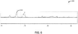
- the single-phase of spheniscidite may be determined using XRD as described in relation to FIG. 6 .
- the term substantially includes the majority of the sample having the specified property.
- the present disclosure provides a high-purity ammonium iron phosphate for use as the primary and/or sole iron phosphate source in the synthesis of nano-sized lithium iron phosphate (LFP) active primary particles for use in cathodes and the methods of making thereof.
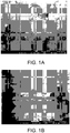
- the ammonium iron phosphate present as the spheniscidite precursor, provides plate-like particles, as illustrated in FIGS. 1A and 1B .
- This material may be used as a precursor for the synthesis of LFP active materials with a primary particle size of about 100 nm and a surface area in a range of 20 m 2 /g to 25 m 2 /g.
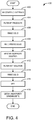
- FIGS. 4 provides an example method for producing the spheniscidite precursor to form a single-phase material with a high level of purity as illustrated in FIGS. 5 and 6 .
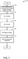
- the high purity spheniscidite is then used as a precursor material to synthesize the LFP active material, an example method provided in FIG. 7 , with a high surface area which demonstrates significantly higher power than current LFP materials.
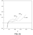
- the LFP active material synthesized from the spheniscidite precursor for use in a battery examples illustrated in FIGS. 25 and 26 , provides improved properties and improved performance at extreme temperatures.
- a synthesized spheniscidite is an ammonium iron phosphate compound with the formula of NH 4 Fe 2 (PO 4 ) 2 OH ⁇ 2H 2 O as the primary or sole iron phosphate component for the synthesis of the cathode material for use in lithium ion secondary batteries.
- Spheniscidite has a specific structure that possesses two 8-membered channels wherein the ammonium, NH 4 , and 1 ⁇ 2 of the water molecules reside.
- the spheniscidite may include from about 35 wt.% to about 30 wt.
- the high-purity spheniscidite has a plate-like shape, as shown in SEMs in FIGS. 1A and 1B and may have less than about 10% total impurities present. With less than 10% total impurities, the materials may provide the improved properties disclosed herein.
- the impurities may include structural impurities determined from XRD and TGA, as well as, composition impurities, such as Na and/or SO 4 impurities, determined from ICP.
- the pure synthesized spheniscidite may be free of K and Al, which appear in naturally occurring spheniscidite.
- the spheniscidite may have less than about 5% impurities present. In yet other embodiments, the spheniscidite may have less than about 2.5% impurities present. In even other examples, the XRDs indicate no impurity peaks over 2%.
- the ICP indicates that the Na and SO 4 impurities are less than .5%.
- the SEMs show the resultant spheniscidite has a plate like morphology with the primary plate particles being about 100 nm along the longest axis of the plate.
- Another aspect of the present disclosure provides methods for preparing the LFP using the synthesized spheniscidite.
- One embodiment utilizes a solvent based system.
- Another embodiment utilizes a water based system.
- the solvent based system may provide particles which include 3D formations.
- the 3D formations may include, but are not limited to, spherical shapes.
- the 3D formations may include collapsed spheres or doughnut-like shaped formations.
- the particles may be substantially spherical.
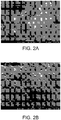
- An LFP is produced which has a primary particle size of about 100 nm, regardless of the solvent system chosen, as illustrated in FIGS. 2A and 2B , a surface area in a range of 25 m 2 /g to 35 m 2 /g, and a secondary d50 particle size in the range of 5 microns to 13 microns, as illustrated in SEMs in FIGS. 3A and 3B .
- the secondary d50 particle size may be in the range of about 8 microns to 13 microns.
- the secondary particles may have a d50 particle size of about 10 microns.
- the methods provided herein include the steps of providing the raw materials to obtain pure spheniscidite, providing a lithium source as well as other reactants to mix with the obtained pure spheniscidite to produce the final LFP active material with the above mentioned properties.
- the methods include at least one of the steps of mixing, filtering, centrifuging, aging, drying, milling, and heating or a combination thereof.
- the methods include the steps of mixing the materials in a predetermined molar ratio and, at specific method steps, controlling the pH to be within a range of 3-8.5 at one step and controlling the pH to be within a range of about 2 to 4 in a subsequent step.
- an aqueous ferrous sulfate solution may be oxidized to a ferric ion to produce spheniscidite, as shown in equation 1 below.
- an LFP material may be formed by the combination of spheniscidite and a lithium source material, as shown in equation 2 below.
- the lithium source is Li 2 CO 3 .
- the spheniscidite and the lithium source are combined to form a LFP active material suitable for use in a cathode of a lithium ion cell.
- a cathode active material is thus formed in a two-step reaction, wherein pure spheniscidite is produce during reaction 1 for subsequent use as a precursor material during reaction 2: Fe SO 4 ⁇ 7 H 2 O + NH 4 OH + NH 4 2 HP O 4 + H 3 PO 4 + H 2 O 2 ⁇ NH 4 Fe 2 PO 4 2 OH ⁇ 2 H 2 O + H 2 SO 4 + H 2 O NH 4 Fe 2 PO 4 2 OH ⁇ 2 H 2 O + Li 2 CO 3 ⁇ LiFePO 4 + H 2 O + CO 2 + NH 3
- the spheniscidite may be obtained by reacting an iron source, an ammonium source, and an oxidant.
- the spheniscidite obtained has a single-phase and a high purity.
- the spheniscidite may have a surface area in a range of 20 m 2 /g to 25 m 2 /g.
- the plate-shaped single-phase spheniscidite precursor may have a surface area of about 23 m 2 /g.
- the iron source compound for making spheniscidite may be a ferrous salt.
- the ferrous salt may be hydrated or anhydrous.
- the ferrous salt, iron (II) salt may be selected from iron (II) sulfate, iron (II) chloride, iron (II) nitrate, iron (II) oxalate, iron (II) oxide, any hydrate thereof, or a mixture thereof.
- iron (II) sulfate heptahydrate, FeSO 4 ⁇ 7H 2 O may be used as the iron source.
- the phosphate source for making spheniscidite may be selected from H 3 PO 4 , P 2 O 5 , NH 4 H 2 PO 4 , (NH 4 ) 2 HPO 4 , (NH 4 ) 3 PO 4 , NaH 2 PO 4 , Na 2 HPO 4 , Na 3 PO 4 , or mixtures thereof.
- a mixture of (NH 4 ) 2 HPO 4 and H 3 PO 4 may be used.
- (NH 4 ) 3 PO 4 may be used.
- the ammonium source may be selected from NH 4 H 2 PO 4 , (NH 4 ) 2 HPO 4 , (NH 4 ) 3 PO 4 , NH 4 OH or mixtures thereof.
- NH 4 OH may be used.
- an oxidizing agent may be included.
- the oxidizing agent may be selected from H 2 O 2 , Na 2 O, NaClO 3 , or mixtures thereof.
- a non-limiting example of an oxidizing agent includes hydrogen peroxide, H 2 O 2 .
- an example method 400 for synthesizing spheniscidite with a high purity is outlined.
- the method may include the reactants of reaction 1 above, wherein during reaction 1, the ferrous ion, Fe 2+ , is oxidized to the ferric ion, Fe 3+ , to form spheniscidite.
- method 400 may include the material processing for reaction 1 including mixing of starting materials, filtering by-products, heating slurry for crystallization, final filtration, and washing with hot solvent, such as water.
- the method may include mixing the starting materials.
- the iron source, phosphate source, ammonium source, and oxidizing agent are mixed.
- the starting materials may be mixed at specific molar ratios.
- the NH4:PO 4 molar ratio may be between about 1.8 to about 3.5, or about 2.0 to about 3.1.
- the solid starting materials may be dissolved in deionized water prior to mixing the starting materials.
- the starting materials may be mixed together in a specific ordering.
- one example of mixing the starting materials includes mixing FeSO 4 ⁇ 7H 2 O, (NH 4 )PO 4 , H 2 O 2 , PO4, and NH 4 OH.
- the mixture comprising the starting materials may have a pH of about 3 to about 8.5.
- the mixture may be stirred for a time before proceeding to step 404.
- the method may include filtering the by-products.
- the mixture from 402 may be centrifuged to separate the by-products.
- the mixture from 402 may be filter pressed to separate the by-products.
- the filtering of the by-products may be performed multiple times to separate fully the by-products. For example, the solution is filtered by centrifuge three times.
- the method may include rinsing the solid obtained during filtering at 404.
- the solid may be rinsed with hot deionized water.
- the solid may be rinsed with hot water multiple times.
- the solid may be continuously rinsed for a period of time.
- the method may include re-dispersing the rinsed solid from 406.
- the solid also referred to as material cakes
- the solution of the re-dispersed solid in deionized water may have a pH controlled to be in the range of about 1.8 to about 3.1.
- the method may include heating the re-dispersed solid solution from 408.
- the solution may be heated in a select temperature range, for example, and not as a limitation, a temperature at or above 85 °C to at or below 95 °C may be used for a time period. In one example, the entire solution may be heated.
- the method may include filtering the hot solution from 410.
- the solution may be filtered using a filter press.
- the solution may be filtered using flask filtration.
- the method may include rinsing the solid recovered at 412 with hot deionized water.
- the rinsing may be done multiple times over a period of time. In another example, the rinsing may be done continuously over a period to time.
- the method may include drying the rinsed solid from 414.
- the solid may be dried at a temperature which removes any volatile compounds present and not desired in the final product.
- the method may include obtaining the spheniscidite.
- the spheniscidite may have a high purity wherein less than 10% of impurities are present in the spheniscidite, not including iron phosphate materials.
- the total impurities left in the final product may be less than 10%, and such material may be considered herein as substantially free of impurities.
- the level of impurities may be determined by ICP, in one example. In other examples, the level of impurities in the spheniscidite may be less than 5%. In yet another example, the level of impurities may be less than 2.5%. The method may then end.
- a crystalline spheniscidite material herein also referred to as ammonium iron phosphate material, may be formed.
- the crystalline spheniscidite material may include from about 25 wt.% to about 30 wt.% iron and from about 15 wt.% to about 20 wt.% phosphorous, and from about 4.6 wt.% to about 5.0 wt.% ammonium; wherein a molar ratio of phosphorus to iron is from about 1 to about 1.25.
- the ammonium iron phosphate may be substantially free of impurities, wherein an XRD may include no impurity peaks over 2%.
- the crystalline spheniscidite material may be a single-phase. Further, in some examples, the crystalline spheniscidite material may have a surface area in the range 20 m 2 /g to 25 m 2 /g.
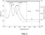
- a high purity spheniscidite further may be determined by TGA and/or XRD illustrated in FIGS. 5 and 6 respectively.
- a high purity spheniscidite product may be determined by the substantial absence of any peaks in the XRD or TGA which correspond to iron phosphates materials of morphologies other than spheniscidite.
- a TGA curve 500 of spheniscidite is provided.
- the TGA curve 502 has a specific shape for the decomposition of pure spheniscidite.
- the derivative TGA curve shows three peaks 504, 506, and 508, which are obtained at specific temperatures.
- the TGA curve may be used to confirm the purity of spheniscidite synthesized, for example using method 400.
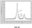
- an XRD pattern 600 of spheniscidite is provided.
- the XRD curve 602 shows characteristic 2 ⁇ peaks.
- the XRD curve may be used to identify phase and purity of the spheniscidite.
- a single-phase and high purity spheniscidite is required to produce the final LFP product as outlined in the present disclosure below.
- the LFP active material for use as a cathode in a battery may be obtained by reacting a high purity spheniscidite, for example synthesized as outlined above in method 400, with a lithium source.
- the spheniscidite may be the primary or sole iron phosphate source during the synthesis of the LFP active material.
- the synthesis may further include a dopant and carbon source.
- the high purity spheniscidite may be the primary or sole source of iron phosphate.
- the lithium source may be selected from Li 2 CO 3 , Li 2 O, LiOH, LiF, LiI or mixtures thereof. In one example, the lithium source may be Li 2 CO 3 .
- the dopant, M may be selected from V, Nb, Ti, Al Mn, Co, Ni, Mg, Zr, oxides thereof or mixtures thereof.
- the dopant may be added in amounts up to 10 mol%. In one example, the dopant may be present at an amount less than 5 mol%.
- the carbon source may be selected from PVB, citric Acid, sugar, PVA, glycerol or mixtures thereof.
- an example method 700 is outlined for the synthesis of LFP from spheniscidite.
- the final LFP material may be formed by combining a lithium source and the spheniscidite by mixing, milling, and chemical reduction with a temperature programmed reaction (TPR) under N 2 .
- TPR temperature programmed reaction
- the resulting LFP active material may then be useable in a cathode of an electrochemical cell.
- the method may include mixing spheniscidite, a lithium source, a dopant, a carbon source, and a solvent to form a slurry.
- the solvent may include an alcohol.
- the solvent may include water.
- the method may include an alcohol or water slurry.
- the dopant and carbon source may vary based on the solvent choice. In some examples, more than one carbon source may be included.
- the lithium source and spheniscidite may be mixed with a dopant and a carbon source in an IPA slurry.
- the slurry may then be milled.
- the method may include milling the mixture of 702.
- the method may include milling for a minimum amount of time.
- the method may include drying the milled mixture of 704.
- the mixture may be dried using a variety of methods known to the industry.
- the method may include firing the dried material of 706.
- the material may be fired to convert the material to LiFePO 4 , LFP, by a temperature programmed reaction (TPR).
- TPR temperature programmed reaction
- the TPR may be run in an inert atmosphere, for example N 2 .
- the dried powder may be converted to LiFePO 4 by TPR in N 2 flow in a tube furnace.
- the TPR profile may include ramping from room temperature and then heating.
- the TPR may further include programmed holds at specific temperatures.
- the method may obtain the lithium iron phosphate, LFP.
- the resulting LFP active materials have a crystalline structure, as illustrated by the XRD pattern provided in FIG. 8 .
- the size of the primary particles, shown in FIGS. 2A and 2B may be between 20 nm to 80 nm, leading to a higher surface area in a range of 25 m 2 /g to 35 m 2 /g final LFP active materials, shown in FIGS. 3A and 3B .
- the use of an alcohol slurry or water slurry results in a similar primary particle size in the LFP, as illustrated in FIGS. 2A and 2B .
- a similar size may be within 5% of one another, for example by surface area and/or volume.
- the secondary particle of the LFP differs based on the solvent slurry.
- the alcohol slurry secondary particle shape is shown in FIG. 3A and the water slurry secondary particle shape is shown in FIG. 3B .
- the alcohol slurry secondary particle shape shows a variety of shapes while the water slurry secondary shape shows spheres that are more exact.
- an XRD pattern 800 of the LFP is shown.
- the XRD curve 802 may be used to determine the purity of the resultant LFP.
- the XRD curve 802 shows characteristic 2 ⁇ peaks, indicating a pure crystalline LFP.
- the XRD curve may be used to identify phase and purity of the LFP.
- a high purity spheniscidite is required to produce the final crystalline LFP product as outlined in the present disclosure wherein the final crystalline LFP product improves battery performance at low temperatures.
- the LFP product may improve battery performance at 0°C or lower.
- the LFP product may improve battery performance at low temperatures of -20°C down to -30°C.
- a resulting LFP active material can be tested in a non-aqueous electrochemical cell.
- the LFP active material serves as the positive electrode against a source of lithium having a total lithium content much greater than the lithium storage capacity of the LFP electrode, such as lithium foil.
- This electrochemical cell construction is often referred to as a lithium half-cell by those skilled in the art of lithium-ion batteries.
- the LFP active material is formulated into an electrode, optionally using a conductive additive, such as carbon, and a polymeric binder.
- the LFP active material electrode is separated from the lithium metal counter electrode, optionally by a microporous polymer separator.
- the cell is then infused with a nonaqueous lithium-conducting liquid electrolyte. The charge and discharge rates of the electrode are sufficiently fast that the electrochemical behavior of the LFP electrode material can be tested.
- an LFP active material is optionally used in an electrochemical cell as a component of either a cathode or an anode, although a cathode is typical.
- An electrochemical cell includes an LFP active material containing electrode and a counter electrode.
- a counter electrode includes an anode base material.
- an anode base material optionally includes silicon, graphitic carbon, silicon carbon composites, tin, Ge, Sb, AI, Bi, As, Li metal, lithium alloys, metal alloys, transition metal oxides, nitride materials, sulfide materials, and combinations thereof.
- An alloy optionally includes one or more of Mg, Fe, Co, Ni, Ti, Mo, and W.
- Illustrative examples of a metal alloy for use as an anode base material include silicon alloys.
- a silicon alloy is optionally and alloy of silicon and Ge, Be, Ag, AI, Au, Cd, Ga, In, Sb, Sn, Zn, or combinations thereof.
- the ratio of the alloying metal(s) to silicon is optionally 5% to 2000% by weight, optionally 5% to 500% by weight, optionally 20% to 60% by weight, based on silicon.
- an anode base material includes a lithium alloy.
- a lithium alloy optionally includes any metal or alloy that alloys with lithium, illustratively including Al, Si, Sn, Ag, Bi, Mg, Zn, In, Ge, Pb, Pd, Pt, Sb, Ti, tin alloys, and silicon alloys.
- the anode base material is or includes: silicon; carbon and graphitic carbon materials such as natural graphite, graphene, artificial graphite, expanded graphite, carbon fibers, hard carbon, carbon black, carbon nanotubes, fullerenes and activated carbon; a composite material of a metal or metal compound and a carbon or graphite material whereby a metal optionally includes lithium and silicon; and a lithium-containing nitride.
- the anode base material also referred to here as the negative electrode, may include non-graphitizable carbon, artificial graphite, and natural graphite combinations of carbonaceous materials with silicon or silicon oxide.
- an electrode base material is not graphite alone in the absence of silicon, lithium, or a metal.
- an anode base material is a composite material of silicon and graphitic carbon that may or may not include a carbon coating and or thermal treatment to stabilize the adhesion of the coating to the surface.
- an anode base material includes a coating, illustratively a carbon coating.
- an anode base material or an LFP active material may or may not be associated with a conductive substrate.
- the substrate is optionally formed of any suitable electronically conductive and impermeable or substantially impermeable material, including, but not limited to, copper, stainless steel, titanium, or carbon papers/films, a nonperforated metal foil, aluminum foil, cladding material including nickel and aluminum, cladding material including copper and aluminum, nickel plated steel, nickel plated copper, nickel plated aluminum, gold, silver, any other suitable electronically conductive and impermeable material or any suitable combination thereof.
- substrates may be formed of one or more suitable metals or combination of metals (e.g., alloys, solid solutions, plated metals).
- an anode base material or LFP active material is not associated with a substrate.
- the inventive LFP active material may be used in an electrode for a secondary battery.
- An electrode is optionally fabricated by suspending a LFP active material and a binder (optionally at 1-10% by weight of solvent) in a solvent to prepare a slurry, and applying the resulting slurry to a current collector, followed by drying and optionally pressing.
- Exemplary binders include PVDF binder solutions in NMP or aqueous polyolefin latex suspensions.
- the solvent used in preparation of the electrode may include, but are not limited to carbonate-based, ester-based, ether-based, ketone-based, alcohol-based, or aprotic solvents. Specific organic solvents such as dimethyl sulfoxide (DMSO), N-methyl pyrrolidone (NMP) and ethylene glycol, and distilled water may be used. Such solvents are known in the art.
- An electrochemical cell is also provided that uses an electrode formed of an LFP active material substantially as provided by the application with embodiments as described herein.
- the electrochemical cells optionally employ a porous electronically insulating separator between the positive and negative electrode materials, and a liquid, gel or solid polymer electrolyte.
- the electrochemical cells optionally have electrode formulations and physical designs and constructions that are developed through methods well-known to those skilled in the art to provide low cell impedance, so that the high power capability of the LFP active material may be utilized.
- the LFP active materials described herein typically contain less than about 5 weight percent, or about 3 weight percent, of any additional phase that does not substantially store ions, but may provide added electrical conductivity.
- additional phases include, for example, carbon, a metal, or an intermetallic phase, such as a metal phosphide, metal carbide, metal nitride, or mixed intermetallic compound, such as metal carbide-nitride or metal carbide-phosphide.
- the electrode materials may include an amount of carbon in the range of 2.1% to 2.5 %.
- the primary and secondary particles of the LFP may have a carbon percentage of about 2.3%.
- the LFP active material typically is formulated into an electrode by standard methods, including the addition of a few weight percent of a polymeric binder, and less than about 10 weight percent of a conductive additive, such as carbon.
- the electrodes are coated onto one or both sides of a metal foil (e.g. substrate), and optionally pressed to a coating thickness of between about 30 micrometers and about 200 micrometers. Such electrodes can be used as the positive or negative electrode in a storage battery.
- An electrochemical cell includes an electrolyte.
- An electrolyte is optionally a solid or fluid electrolyte.
- the electrolyte includes a lithium salt and a non-aqueous organic solvent.
- a lithium salt is optionally LiPF 6 , LiBF 4 , LiSbF 6 , LiAsF 6 , LiN(SO 2 C 2 F 5 ) 2 , Li(CF 3 SO 2 ) 2 N, LiFSI, LiTFSI, LiN(SO 3 C 2 F 5 ) 2 , LiC 4 F 9 SO 3 , LiClO 4 , LiAlO 2 , LiAlCl 4 , LiCl, LiI, or LiB(C 2 O 4 ) 2 (lithium bis(oxalato)borate; LiBOB).
- the lithium salt is optionally present in a concentration ranging from about 0.1 M to about 2.0 M.
- an electrolyte may have excellent performance and lithium ion mobility due to optimal electrolyte conductivity and viscosity.
- a method including introducing an iron (II) salt, a phosphate source, an ammonium source, and an oxidizing agent into an aqueous solution to form a mixture.
- the mixture may be filtered to recover a solid by-product and then the solid by-product may be re-dispersed into an aqueous solution.
- the aqueous solution may be heated and then filtered to recover a solid.
- the solid may be dried to obtain a high purity spheniscidite with a formula of NH 4 Fe 2 (PO 4 ) 2 OH ⁇ 2H 2 O.
- the high purity spheniscidite may be a single-phase.
- the iron (II) salt may be selected from iron (II) sulfate, iron (II) chloride, iron (II) nitrate, any hydrate thereof, or a mixture thereof.
- the phosphate source may be selected from H 3 PO 4 , P 2 O 5 , NH 4 H 2 PO 4 , (NH 4 ) 2 HPO 4 , (NH 4 ) 3 PO 4 , NaH 2 PO 4 , Na 2 HPO 4 ,Na 3 PO 4 , or mixtures thereof.
- the ammonium source may be selected from NH 4 H 2 PO 4 , (NH 4 ) 2 HPO 4 , (NH 4 ) 3 PO 4 , NH 4 OH or mixtures thereof.
- the oxidizing agent also may be selected from H 2 O 2 , Na 2 O, NaClO 3 , or mixtures thereof.
- the method may further include mixing the obtained high purity spheniscidite, a lithium source, a dopant, and a carbon source, adding a solvent to produce a slurry, milling the slurry, drying the milled slurry, and firing the dried milled slurry to obtain the lithium iron phosphate, wherein the lithium iron phosphate comprises a substantially olivine crystalline phase, a primary particle in the range of 20 nm to 80 nm, a secondary particle with a d50 in the range of 5 ⁇ m to 13 ⁇ m, and a surface area of 25 m 2 /g to 35 m 2 /g, a carbon percentage of about 2.3%.
- the lithium iron phosphate may be substantially in an olivine crystalline phase where there may be less than 5 weight percent of any additional phases which do not substantially store ions.
- the lithium iron phosphate may improve battery performance at low temperatures in comparison to current lithium iron phosphate materials.
- the current lithium iron phosphate materials may be stoichiometric lithium iron phosphate materials, wherein the elements are present in the ratios prescribed by the formula LiFePO 4 .
- primary particles may be obtained of about 20 nm to about 80 nm.
- the method may include a solvent where the solvent is water and/or a compound including an alcohol functional group.
- a lithium iron phosphate comprising crystalline primary particles and secondary particles, wherein the primary particles are formed from a plate-shaped single-phase ammonium iron phosphate spheniscidite precursor and a lithium source.
- the LFP herein also referred to as a spheniscidite-derived LFP, may be formed from the spheniscidite precursor and show a specific LFP phase behavior.
- the spheniscidite-derived LFP may exhibit different phase behavior than a conventional LFP, even when the conventional LFP has similar characteristics (for example primary particle size, specific surface area, or similar XRD peak broadening).
- an example phase diagram for the LFP illustrates the extended solid-solution range of the LFP in comparison to the conventional LFP of similar physical characteristics, e.g. particle size and/or specific surface area, for example an LFP of similar physical characteristics but without pure ammonium iron phosphate spheniscidite precursor.
- the similar characteristics may be a similar size within 5% of one another and/or within 5-10% of surface areas of one another.
- the LFP phase behavior may include an extended solid-solution range, which may be due to the use of the pure ammonium iron phosphate spheniscidite precursor.
- the LFP phase behavior may translate to improved battery properties, for example when used in lithium ion cells.
- the LFP may show improved temperature performance, such as at low temperature, and improved capacity.
- the two-phase field may occur over a smaller range of Li concentration for the LFP at the same temperature in comparison to conventional LFP materials having similar particle sizes. This is contrary to the conventional way of thinking where the two-phase field shrinks with decreasing particle size, and has the same behavior for the same particle sizes.
- the LFP may also show extended solid-solution ranges in comparison to conventional LFP's of similar size over a range of temperatures.
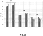
- 2900 and 2904 of FIG. 29 show voltage versus discharge capacity curves at a discharge rate of 10C (current density to discharge the full capacity of the battery device in 1/10 of an hour) for the LFP 2902, which illustrates the extended solid-solution range of the LFP, in comparison to the conventional LFP 2906.
- the LFP and the conventional LFP have similar physical characteristics, e.g. particle size and/or specific surface area. The similar characteristics may be a similar size within 5% of one another and/or within 5-10% of surface areas of one another.
- the shapes of the two discharge curves illustrate that the LFP material 2902 provides an improved battery material for high-rate applications as compared to the conventional LFP 2906.
- the shape of the discharge curves at the last 25% of the discharge show clear differences as the voltage begins to decrease.
- the LFP 2902 curve shows a sharper, defined change in slope, occurring just above 3V.
- the discharge curve shape of the LFP 2902 may illustrate the change in the mode of lithium intercalation within the active material particles. More specifically, illustrated by the flatter portion of the discharge curve, the LFP material may be lithiated via a two-phase reaction, where two distinct crystalline phases co-exist (i.e. the LFP phase behavior). A first phase may be present in a predominately lithiated state and a second phase may be present in a predominately unlithiated state.
- a one-phase lithiation reaction may occur, which may also enhance faster lithium intercalation kinetics.
- the percentage of the total lithiation reaction occurring in a two-phase versus a one-phase lithiation reaction may control the overall rate performance of the active cathode material.
- the conventional LFP 2906 shows a distinctly different discharge voltage curve.
- the overall voltage of the battery employing the conventional LFP is lower in comparison to the LFP 2902.
- the discharge curve of the conventional LFP 2906 is more curved and continuously rounded, especially during the last 25% of the discharge.
- the conventional LFP 2906 does not show a sharp transition between the two nearly linear sloping regions.
- the characteristics of the conventional LFP 2906 show a material with higher overall net impedance. The impedance may limit a battery from completely discharging all its capacity, as illustrated by the shorter capacity at the end of discharge at 2V for the conventional LFP 2906.
- the smoothly sloping nature of the discharge curve of the conventional LFP 2906 does not illustrate a clear transition from a two-phase to a single phase lithiation reaction, as is seen the LFP 2902.
- the LFP 2902 prepared from pure ammonium iron phosphate spheniscidite precursor, has an improved rate performance in comparison to the conventional LFP 2906.
- the LFP may be concluded to have a mode of lithiation, more specifically a phase change behavior when the LFP is sufficiently discharged, which is different from the conventional LFP.
- the LFP may include an LFP phase behavior.
- the differences in shape of the discharge capacity curves, as described above and illustrated in 2900 and 2904 for the LFP 2902 and the conventional LFP 2906, may indicate that the LFP has less polarization than the conventional LFP.
- the conventional LFP 2906 discharge curve does not show a clear break in the two slope areas, indicating that the behavior may be controlled by polarization, whereas the LFP 2902 discharge curve shows a more clear break in the two slope areas, indicating that the behavior has less polarization.
- polarization in an electrochemical process may lower the efficiency of the process.
- the lower polarization and clear breaks in the two-slope areas may indicate the presence of a wider solid-solution range in the spheniscidite-derived LFP.
- the LFP phase behavior may exhibit characteristics such as an extended solid-solution range.
- the spheniscidite-derived LFP may possess different phase behavior from standard materials, including, but not limited to, extended solid-solution ranges at the same temperature and particle size.
- the extended solid-solution range in the LFP may be greater at the same temperature and particle size in comparison to current LFP materials.
- the lithium iron phosphate may exhibit an LFP phase behavior wherein the LFP phase behavior includes, as a non-limiting example, an extended solid solution range where x in Li x FePO 4 exceeds 0.2 at Li-poor compositions, and is less than 0.8 at Li-rich compositions, at 45°C for a primary particle size of 20nm-80nm.
- an extended solid solution range where x in Li x FePO 4 exceeds 0.1 at Li-poor compositions, and is less than 0.15 at Li-rich compositions, at 0°C for a primary particle size of 20nm-80nm may be seen for the LFP.
- the LFP phase behavior may provide extended solid-solutions in a wider range of lithium compositions over which a solid-solution occurs.
- the LFP phase behavior may be such that the difference in the solid-solution ranges is a wider range of Li composition over which a solid solution occurs at low or at high states of charge (or high and low overall Li concentration).
- the modifications of the LFP phase behavior may provide for improved battery performance at a variety of temperatures, for example low temperatures, and improved capacity in comparison to current lithium iron phosphate materials.
- the use of the pure ammonium iron phosphate spheniscidite precursor may be to provide a precursor material which introduces an LFP phase behavior into the synthesized lithium iron phosphate material, resulting in improved performance in battery applications.
- the modified LFP phase behavior may result in extended solid-solution ranges in the lithium iron phosphate.
- This LFP phase behavior is an unexpected result when compared to other LFP materials having similar specific surface area, particle size, or exhibiting similar x-ray diffraction peak broadening. This is at least partially due to the fact that spheniscidite-derived LFP exhibits different phase behavior in comparison to a conventional LFP material of the same BET specific surface area (or primary particle size, or exhibiting the same X-ray peak broadening).
- the markedly superior power at low temperature of battery cells having the spheniscidite- derived LFP may be obtained despite this material having a lower BET specific surface area and less X-ray peak broadening. Therefore, in this example, larger LFP primary crystallite size does not result in an inferior performance, due to the LFP phase behavior.
- the LFP phase behavior and improved performance characteristics appear not to be due to a shorter diffusion distance at the crystallite level. Also, unexpectedly, the performance may not be explained by the presence of conductive impurity phases since the amount of those phases can be widely varied with composition, heat treatment temperature, and firing atmosphere, and have not previously resulted in the exceptional low temperature behavior of the disclosed LFP.
- olivine cathode materials may suppress the two-phase immiscibility field inherent to LFP and thereby avoid the first order phase transition.
- Published scientific literature on olivine cathode materials indicate that suppressing the two-phase immiscibility field inherent to LFP, and thereby avoiding the first-order phase transition and its associated high mechanical strain, may be responsible for obtaining high power.
- the range of Li concentration over which immiscible solid phases of differing Li concentration appear, at any given temperature may be decreased by creating defects and atomic disorder.
- the immiscibility field in pure LixFePO 4 is relatively symmetric in composition space between Li concentrations of zero and one, the effects of diminished immiscibility may generally be seen at low and high Li concentrations, corresponding to high and low states of charge of the corresponding battery cell.
- the extent of solid solution at low overall Li concentrations is lower than 20% at an equivalent spherical particle size obtained from the BET specific surface area of 34nm, is lower than 10% at a particle size of 42nm, and is lower than 5% at a particle size of 100nm.
- the unexpected LFP phase behavior of the spheniscidite-derived material has an increased extended solid-solution range at the same temperature and particle size in contrast to prior LFP materials.
- the LFP phase behavior of the spheniscidite-derived material may include a lithium amount in solid solution that is greater than or less than 20% of a stoichiometric lithium iron phosphate of the same particle size.
- the phase behavior includes a lithium amount in solid solution that is greater than or less than 5% of a stoichiometric lithium iron phosphate of the same particle size.
- the lithium iron phosphate may show a lithium nonstoichiometry, i.e. an extended solid-solution range. The lithium iron phosphate extended solid-solution allows for the crystalline structure, in which lithium may be delithiated or lithiated, to remain the same.
- the LFP phase behavior of the LFP shows a homogeneous solid that may exist over a wider range of lithiation and delithiation (i.e. lithium amount) in comparison to conventional LFP material not synthesized using a pure ammonium iron phosphate spheniscidite precursor.
- the LFP phase behavior of the LFP shows an unexpectedly wide range where the solid-solution exists as compared with the conventional LFP's sharing similar physical characteristics.
- the phase behavior may show a two-phase field wherein x may be 0.2 ⁇ x ⁇ 0.8 for Li x FePO 4 at a temperature of about 45 °C and the extended solid-solution range occurs outside of the two-phase field range.
- the spheniscidite-derived LFP may include one or more structural differences from prior LFPs. These structural differences may include subtle morphology differences or differences in crystal lattice dimensions, which may produce differences in lattice strain at high and low lithium occupancy. Such structural differences may enable an unexpected and dramatic difference in lithiation, such as where the overall crystallite/grain dimensions and resulting lithium diffusion lengths are similar. The mechanistic and possibly structural differentiation of the disclosed LFP material may result in startling and dramatic difference in rate performance.
- the spheniscidite-derived LFP further provides an improvement in the rate of lithium insertion/extraction.
- the LFP phase behavior of the spheniscidite-derived material may result in the rate of lithium insertion/extraction being improved, e.g. at a rate of 20C, 90% discharge capacity is retained compared to C/10.
- a comparative material is capable of only 80% discharge capacity at 20C being retained.
- impurities may be present on the M1 site in an olivine lithium iron phosphate, where the M1 site is the lithium site in the olivine structure. Minimizing the amount of impurities on the M1 site may impove battery performance, such as with the disclosed LFP.
- the spheniscidite-derived LFP may minimize the amount of non-lithium atoms, i.e. impurities, on the M1 site in comparison to LFPs not synthesized using spheniscidite.
- the impurities on the M1 site may be less than about 5 %. In another example, the impurities on the M1 site may be less than about 1% of the sites.
- a spheniscidite material is formed as per reaction 1 wherein the method may include the ferrous ion, Fe 2+ , oxidized to the ferric ion, Fe 3+ , to form spheniscidite.
- the resulting spheniscidite has the following properties listed in Table 1: Table 1: Morphology NH 4 :P ratio NH 4 OH (g) pH 1 st step pH 2 nd step P/Fe Color Texture FCC C/5 10C C% N% BET Spheniscidite/trace Phosphosiderite 2.014 15.00 2.96 2.04 1.2 Yellow Soft 154 163 149 2.67 0.30 30.8 Spheniscidite 2.137 22.58 3.09 2.20 1.02 Yellow Soft 158 169 154 2.48 0.20 29.8
- a conductive additive may be added to the spheniscidite along with a metal oxide dopant, and a carbon additive.
- the mixture may be mixed with a solvent, for example, an alcohol based solvent to form a slurry.
- the slurry may then be milled.
- the milled slurry may then be dried and sieved.
- the dried powder may be fired to convert the material into the final LFP product.
- a conductive additive may be added to the spheniscidite, along with a metal salt dopant, at least one carbon additive, followed by mixing in a water solvent slurry. In some examples, more than one carbon additive may be used. The slurry may then be milled. The milled slurry may then be dried. The dried slurry may then be fired to convert the material into the final LFP product.
- the resulting LFP active material is used to form a Swagelok electrode that includes 79% active material, 10% carbon, and 11% binder mass ratio to make a loading of 0.45-0.49 mAhr / cm 2 .
- the Swagelok half-cells are charged at C / 2 to 3.8V CCCV and discharged with CC to 2 V with different C-rates.
- the discharge charge storage capacities at different C-rates were measured, and the rate-capability calculated.
- the rate-capability at 10C is greater than 130 mAh/g in a Swagelok half-cell.
- FIGS. 9 through 24 the performance of an electrochemical cell comprising the LFP synthesized from pure spheniscidite is illustrated in comparison to an electrochemical cell comprising current LFP materials.
- the electrochemical cell comprises a cathode, an anode, an electrolyte, and a separator.
- the anode, the separator, and the electrolyte in the electrochemical cell were the same for a given test.
- FIG. 9 the first charge capacity of the LFP material used in a cathode is illustrated.
- the first charge capacity of the LFP 902 synthesized from pure spheniscidite is improved over current LFP materials 904 and 906 used in cathodes in Li-ion cells.
- FIG. 10 the first discharge capacity of the LFP material used in a cathode is illustrated.
- the first discharge capacity of the LFP 1002 synthesized from pure spheniscidite is improved over current LFP materials 1004 and 1006 used in cathodes in Li-ion cells.
- a percentage of first charge capacity of the LFP synthesized from spheniscidite is compared to current LFP materials.
- the LFP 1102 synthesized from spheniscidite shows percentage of first charge capacity similar to current LFP 1104 and slightly lower than current LFP 1106
- an absolute capacity loss of the LFP synthesized from spheniscidite is compared to current LFP materials.
- the LFP 1202 synthesized from spheniscidite shows a lower absolute capacity loss compared to the current LFP 1204 and 1206 materials.
- FIG. 13 an alternating current resistance (ACR) impedance for cells with the LFP material used in a cathode is illustrated.
- ACR alternating current resistance
- FIG. 14 a direct current resistance (DCR) impedance for cells with the LFP material used in a cathode is illustrated.
- DCR direct current resistance
- FIG. 15 the capacity retention after 3 days of aging is shown for the LFP material used in a cathode is illustrated.
- the LFP 1502 synthesized from spheniscidite shows a similar capacity retention in comparison to the current LFP materials 1504 and 1506.
- the average cathode 1604 and anode 1608 thickness after calendering and the average cathode 1602 and anode 1606 thickness after formation show values that indicate acceptable swelling of the electrode comprising the LFP synthesized from spheniscidite.
- FIG. 17 the hybrid pulse power characterization (HPPC) DCR impedance at 1s and 20s for the LFP material used in a cathode is illustrated at 23°C.
- the 1s DCR results are illustrated for the LFP 1702 synthesized from spheniscidite and the current LFP 1704 and 1706 materials and the 20s DCR results are illustrated for the LFP 1708 synthesized from spheniscidite and the current LFP 1710 and 1712 materials.
- the LFP 1702 and 1708 shows reduced DCR at both the 1s and 20s DCR.
- FIG. 18 the hybrid pulse power characterization (HPPC) DCR impedance at 10s of the LFP material used in a cathode is illustrated at 23°C.
- the 10s DCR shows results similar to the 1s and 20s results illustrated in FIG. 17 above.
- the LFP 1802 synthesized from spheniscidite shows reduced DCR compared to the current LFP 1804 and 1806 materials.
- FIG. 19 the hybrid pulse power characterization (HPPC) at -20°C at 1s and 20s pulse power for the LFP synthesized from spheniscidite.
- the 1s DCR results are illustrated for the LFP 1902 synthesized from spheniscidite and the current LFP 1904 and 1906 materials and the 20s DCR results are illustrated for the LFP 1908 synthesized from spheniscidite and the current LFP 1910 and 1912 materials.
- the LFP 1902 and 1908 shows reduced DCR at both the 1s and 20s DCR and shows 40% improvement at 1s and 20% improvement at 20s at a 50% SOC at low temperature.
- the disclosed electrode material the LFP synthesized from spheniscidite
- the electrochemical cells prepared for testing may include the same components, such as the anode, separator, electrolyte, in order to provide a comparison between the cathode electrode materials.
- FIG. 20 the double layer pouch cell (DLP) with 0.5x electrode loading and 5C for 30secat 50% SOC is shown.
- the LFP synthesized from spheniscidite shows a 45% improvement in average DCR as compared to the current LFP material and provides less than 9 ohms impedance at 50% SOC.
- the LFP synthesized from spheniscidite shows improved cold temperature performance.
- FIG. 21 the voltage profile for a 10C discharge to 100% depth of discharge (DOD for the LFP synthesized from spheniscidite is shown.
- the voltage profile 2002 illustrates that the LFP synthesized from spheniscidite and shows an improvement in energy as compared to the current LFP 2004 material.
- FIG. 22 the normalized rate capability at various discharge rates of the LFP synthesized from spheniscidite compared to current LFP materials is shown.
- the LFP 2102 shows increased rate capability compared to current LFP materials 2106 and 2104.
- FIG. 23 the direct current resistance pulse discharge at -30°C at 10s for the LFP synthesized from spheniscidite compared to current LFP materials is shown.
- the LFP 2202 synthesized from spheniscidite shows about a 20% decrease in DCR and 40% increase in power (refer to 2208) as compared to current LFP 2204 and a larger improvement over current LFP 2206.
- FIG. 24 the power resulting from a cold crank test at -30°C over time, measured in seconds, for the LFP synthesized from spheniscidite compared to current LFP materials is shown.
- the LFP 2302 synthesized from spheniscidite shows increased power as compared to the current LFP 2304 and 2306 materials over time measured in seconds.
- FIG. 25 the alternating current impedance for the LFP synthesized from spheniscidite compared to current LFP materials is shown.
- the LFP 2402 synthesized from spheniscidite shows the lowest charge transfer resistance.
- the current LFP 2404 and 2406 materials show higher charge transfer resistance.
- a prismatic cell is defined as a cell having a rectangular profile within a plane perpendicular to the length of the cell.
- Prismatic cells should be distinguished from round (cylindrical) cells that have a circular profile within this plane.
- an electrode assembly which may include the disclosed LFP electro-active material.
- the LFP active material synthesized from spheniscidite may be present as a cathode or anode.
- multiple cathodes and anodes may be arranged as parallel alternating layers.
- a stackable cell electrode assembly 2500 is shown.
- the electrode assembly 2500 is shown to include seven cathodes 2502a-2502g and six anodes 2504a-2504f.
- the cathodes may comprise the LFP synthesized from spheniscidite as described above.
- the anodes may comprise the LFP synthesized from spheniscidite.
- Adjacent cathodes and anodes are separated by separator sheets 2506 to electrically insulate the adjacent electrodes while providing ionic communication between these electrodes.
- Each electrode may include a conductive substrate (e.g. metal foil) and one or two active material layers supported by the conductive substrate. Each negative active material layer is paired with one positive active material layer.
- outer cathodes 2502a and 2502g include only one positive active material facing towards the center of assembly 2500.
- Conductive tabs may be used to provide electronic communication between electrodes and conductive elements, for example.
- each electrode in electrode assembly 2500 may have its own tab. Specifically, cathodes 2502a-2502g are shown to have positive tabs, 2510 while anodes 2504a-2504f are shown to have negative tabs.
- FIGS. 27A and 27B a wound cell example 2600 is illustrated in which two electrodes are wound into a jelly roll and housed within a container.
- the container housing the negative electrode, the positive electrode, the nonaqueous electrolyte and the separator.
- the LFP synthesized from pure spheniscidite having primary particles in the range of 20nm to 80 nm and a surface area in a range of 25 m 2 /g to 35 m 2 /g shows improved properties when used as an electroactive material in a battery.
- the surface area of the LFP synthesized from pure spheniscidite may be about 30 m 2 /g.
- the LFP shows reduced DCR, about 50% as illustrated in the HPPC data above, an increased power by about 40 % during cold cranking, an increased rate capacity retention, and lowered charge transfer resistance.
- a XRD shows diffraction data illustrating that the synthesized LFP 2802 has a crystallite size within the range of current LFP crystallite sizes 2804 and 2806, as indicated by the full width at half maximum of the peaks.
- the synthesized LFP may have a modified LFP phase behavior.
- the LFP phase behavior of the synthesized LFP may include the extended solid solution range, wherein the extended solid solution range has a composition Li x FePO 4 , where x exceeds 0.2 at Li-poor compositions and is less than 0.8 at Li-rich compositions, at about 45°C; and wherein the primary particles have a particle size in the range of 20 nm to 80 nm.
- the extended solid solution range has a composition Li x FePO 4 , where x exceeds 0.1 at Li-poor compositions, and is less than 0.15 at Li-rich compositions, at 0°C for a primary particle size of 20nm-80nm may be seen for the LFP.
- the solid-solution range of the LFP having a primary particle size of 20-80nm, wherein the particle size is comparable to current, stoichiometric, LFP materials, is extended.
- current LFP materials do not show the same improved battery performance, for example at low temperatures, and therefore do not present a similar phase behavior as the spheniscidite-derived LFP.
- the LFP phase behavior may be unique to the synthesized LFP as the LFP is prepared using a pure ammonium iron phosphate spheniscidite precursor, which is not present in current LFP materials.
- the current disclosure provides an LFP material with specific characteristics synthesized from a pure spheniscidite, used as the primary or sole iron phosphate source, which surprisingly improves battery performance.
- the LFP material may be synthesized as described above from a plate-shaped single-phase ammonium iron phosphate precursor and a lithium source such that it exhibits a different solid phase behavior, specifically an extended solid-solution range as described above.
Landscapes
- Chemical & Material Sciences (AREA)
- Inorganic Chemistry (AREA)
- Chemical Kinetics & Catalysis (AREA)
- Electrochemistry (AREA)
- General Chemical & Material Sciences (AREA)
- Organic Chemistry (AREA)
- Composite Materials (AREA)
- Crystallography & Structural Chemistry (AREA)
- Battery Electrode And Active Subsutance (AREA)
- Secondary Cells (AREA)
Claims (8)
- Matériau de sphéniscidite cristallin à utiliser dans une électrode, comprenant :d'environ 25 % en poids à environ 30 % en poids de fer ;d'environ 15 % en poids à environ 20 % en poids de phosphore ;d'environ 4,6 % en poids à environ 5,0 % en poids d'ammonium ;dans lequel un rapport molaire du phosphore au fer est d'environ 1 à environ 1,25 ; etle sphéniscidite cristallin est un phosphate de fer ammonium comprenant moins de 10 % d'impuretés totales, et dans lequel le matériau de sphéniscidite cristallin a une morphologie en forme de plaque ; etle phosphate de fer ammonium a une formule de NH4Fe2(PO4)2OH∗2H2O.
- Matériau de sphéniscidite cristallin selon la revendication 1, dans lequel le matériau de sphéniscidite cristallin est monophasique ou dans lequel le sphéniscidite cristallin a une surface spécifique comprise entre 20 m2/g et 25 m2/g ou dans lequel un XRD ne comprend aucun pic d'impureté supérieur à 2 %.
- Procédé de formation d'un phosphate de fer ammonium à utiliser pour fabriquer un matériau actif d'électrode, comprenant :(a) l'introduction d'un sel de fer (II), d'une source de phosphate, d'une source d'ammonium et d'un agent oxydant dans une solution aqueuse pour former un mélange ;(b) la filtration du mélange pour récupérer un sous-produit solide ;(c) la redispersion du sous-produit solide dans une solution aqueuse ;(d) la chauffe de la solution aqueuse ;(e) la filtration de la solution pour récupérer un solide ; et(f) le séchage du solide pour obtenir un sphéniscidite de haute pureté avec une formule de NH4Fe2(PO4)2OH∗2H2O.
- Procédé selon la revendication 3, dans lequel le sel de fer (II) est choisi parmi le sulfate de fer (II), le chlorure de fer (II), le nitrate de fer (II), tout hydrate de ceux-ci, ou un mélange de ceux-ci ou dans lequel la source de phosphate est choisie parmi H3PO4, P2O5, NH4H2PO4, (NH4)2HPO4, (NH4)3HPO4, NaH2PO4, Na2HPO4,Na3PO4, ou leurs mélanges ou dans lequel la source d'ammonium est choisie parmi NH4H2PO4, (NH4)2HPO4, (NH4)3PO4, NH4OH ou leurs mélanges ou dans lequel l'agent oxydant est choisi parmi H2O2, Na2O, NaClO3, ou leurs mélanges ou comprenant en outre le rinçage du sous-produit solide et/ou du solide après filtration.
- Procédé selon la revendication 3, dans lequel le sphéniscidite de haute pureté est un monophasique.
- Procédé selon la revendication 3, dans lequel le sphéniscidite de haute pureté a une morphologie en forme de plaque.
- Procédé de formation d'un lithium-fer-phosphate à partir d'un sphéniscidite cristallin de morphologie en forme de plaque synthétisé par le procédé de la revendication 6, comprenant :(a) le mélange de la sphéniscidite, d'une source de lithium, d'un dopant et d'une source de carbone ;(b) l'ajout d'un solvant pour produire une suspension ;(c) le broyage de la suspension ;(d) le séchage de la suspension broyée ; et(e) la cuisson de la suspension broyée séchée pour obtenir le lithium-fer-phosphate, dans lequel le lithium-fer-phosphate comprend une phase cristalline essentiellement d'olivine, une particule primaire dans la plage de 20 nm à 80 nm, une particule secondaire avec d50 dans la plage de 5 µm à 13 µm, et une surface spécifique de 25 m2/g à 35 m2/g, un pourcentage de carbone d'environ 2,3 % ; etdans lequel le lithium-fer-phosphate améliore les performances de la batterie à basse température par rapport aux matériaux actuels de lithium-fer-phosphate.
- Procédé selon la revendication 7, dans lequel la suspension est broyée pour obtenir des particules primaires d'environ 20 nm à environ 80 nm ou dans lequel le solvant est de l'eau ou dans lequel le solvant est un composé comprenant un groupe fonctionnel alcool ou dans lequel les basses températures sont à 0° C ou moins.
Priority Applications (1)
| Application Number | Priority Date | Filing Date | Title |
|---|---|---|---|
| EP18174808.8A EP3412631B1 (fr) | 2014-03-07 | 2015-03-06 | Matériaux d'électrode haute puissance |
Applications Claiming Priority (3)
| Application Number | Priority Date | Filing Date | Title |
|---|---|---|---|
| US201461949596P | 2014-03-07 | 2014-03-07 | |
| US201562103987P | 2015-01-15 | 2015-01-15 | |
| PCT/US2015/019313 WO2015134948A1 (fr) | 2014-03-07 | 2015-03-06 | Matériaux d'électrode de forte puissance |
Related Child Applications (2)
| Application Number | Title | Priority Date | Filing Date |
|---|---|---|---|
| EP18174808.8A Division EP3412631B1 (fr) | 2014-03-07 | 2015-03-06 | Matériaux d'électrode haute puissance |
| EP18174808.8A Division-Into EP3412631B1 (fr) | 2014-03-07 | 2015-03-06 | Matériaux d'électrode haute puissance |
Publications (3)
| Publication Number | Publication Date |
|---|---|
| EP3114081A1 EP3114081A1 (fr) | 2017-01-11 |
| EP3114081A4 EP3114081A4 (fr) | 2017-12-13 |
| EP3114081B1 true EP3114081B1 (fr) | 2021-12-29 |
Family
ID=54055929
Family Applications (2)
| Application Number | Title | Priority Date | Filing Date |
|---|---|---|---|
| EP15758176.0A Active EP3114081B1 (fr) | 2014-03-07 | 2015-03-06 | Matériaux d'électrode de forte puissance |
| EP18174808.8A Active EP3412631B1 (fr) | 2014-03-07 | 2015-03-06 | Matériaux d'électrode haute puissance |
Family Applications After (1)
| Application Number | Title | Priority Date | Filing Date |
|---|---|---|---|
| EP18174808.8A Active EP3412631B1 (fr) | 2014-03-07 | 2015-03-06 | Matériaux d'électrode haute puissance |
Country Status (7)
| Country | Link |
|---|---|
| EP (2) | EP3114081B1 (fr) |
| JP (2) | JP6767266B2 (fr) |
| KR (1) | KR102423392B1 (fr) |
| CN (1) | CN106061892B (fr) |
| AU (4) | AU2015226940B2 (fr) |
| TW (1) | TW201603367A (fr) |
| WO (1) | WO2015134948A1 (fr) |
Families Citing this family (3)
| Publication number | Priority date | Publication date | Assignee | Title |
|---|---|---|---|---|
| CN108201895B (zh) * | 2017-10-18 | 2020-08-28 | 扬州明晟新能源科技有限公司 | 一种具有可见光响应的新型SPH–Ag光催化剂及其制备方法 |
| CN107910552B (zh) * | 2017-11-14 | 2020-06-09 | 山东黄蓝伟业新能源科技有限公司 | 一种羟基磷酸铁铵的制备方法 |
| CN113666350B (zh) * | 2021-08-19 | 2022-10-25 | 湖北虹润高科新材料有限公司 | 一种可灵活调节晶体结构的二水磷酸铁及其制备方法 |
Family Cites Families (13)
| Publication number | Priority date | Publication date | Assignee | Title |
|---|---|---|---|---|
| EP0845825B1 (fr) * | 1996-06-14 | 2004-01-21 | Hitachi Maxell, Ltd. | Batterie secondaire au lithium |
| US6235427B1 (en) | 1998-05-13 | 2001-05-22 | Fuji Photo Film Co., Ltd. | Nonaqueous secondary battery containing silicic material |
| JP4151210B2 (ja) * | 2000-08-30 | 2008-09-17 | ソニー株式会社 | 正極活物質及びその製造方法、並びに非水電解質電池及びその製造方法 |
| KR100490549B1 (ko) * | 2003-02-07 | 2005-05-17 | 삼성에스디아이 주식회사 | 카본 화합물이 흡착된 정극 활물질 및 이를 채용한 리튬전지 |
| JP5004413B2 (ja) * | 2004-08-20 | 2012-08-22 | 日本コークス工業株式会社 | 燐酸アンモニウム鉄及びリチウムイオン二次電池用正極材料の製造方法、並びにリチウムイオン二次電池 |
| CN101244813B (zh) * | 2007-02-15 | 2010-09-29 | 比亚迪股份有限公司 | 碱式磷酸铁铵及制备方法、磷酸铁的制备方法及磷酸亚铁锂的制备方法 |
| DE102007049757A1 (de) * | 2007-10-16 | 2009-04-23 | Chemische Fabrik Budenheim Kg | Eisen(III)orthophosphat für Li-Ionen-Akkumulatoren |
| TWI466370B (zh) * | 2008-01-17 | 2014-12-21 | A123 Systems Inc | 鋰離子電池的混合式金屬橄欖石電極材料 |
| DE102009001204A1 (de) * | 2009-02-26 | 2010-09-02 | Chemische Fabrik Budenheim Kg | Herstellung von Eisenorthophosphat |
| TWI343706B (en) | 2009-07-13 | 2011-06-11 | Ind Tech Res Inst | Isolation circuit |
| CN102625959B (zh) * | 2009-08-25 | 2015-09-09 | A123系统有限责任公司 | 用于锂离子电池的具有改良的比容量和能量密度的混合金属橄榄石电极材料 |
| US20130244100A1 (en) * | 2012-03-15 | 2013-09-19 | Imra America, Inc. | Iron phosphates: negative electrode materials for aqueous rechargeable sodium ion energy storage devices |
| CN103268938A (zh) * | 2013-01-22 | 2013-08-28 | 合肥国轩高科动力能源股份公司 | 一种锂离子正极材料磷酸铁锰锂固溶体的制备方法 |
-
2015
- 2015-03-06 WO PCT/US2015/019313 patent/WO2015134948A1/fr active Application Filing
- 2015-03-06 EP EP15758176.0A patent/EP3114081B1/fr active Active
- 2015-03-06 AU AU2015226940A patent/AU2015226940B2/en active Active
- 2015-03-06 TW TW104107272A patent/TW201603367A/zh unknown
- 2015-03-06 KR KR1020167024994A patent/KR102423392B1/ko active IP Right Grant
- 2015-03-06 CN CN201580012036.4A patent/CN106061892B/zh active Active
- 2015-03-06 JP JP2016555769A patent/JP6767266B2/ja active Active
- 2015-03-06 EP EP18174808.8A patent/EP3412631B1/fr active Active
-
2018
- 2018-06-28 AU AU2018204689A patent/AU2018204689B2/en active Active
-
2019
- 2019-07-10 AU AU2019204949A patent/AU2019204949B2/en active Active
- 2019-07-10 AU AU2019204947A patent/AU2019204947B2/en active Active
-
2020
- 2020-06-04 JP JP2020097533A patent/JP7293167B2/ja active Active
Also Published As
| Publication number | Publication date |
|---|---|
| AU2019204947B2 (en) | 2020-07-16 |
| AU2015226940B2 (en) | 2018-07-12 |
| AU2019204949B2 (en) | 2020-07-30 |
| JP6767266B2 (ja) | 2020-10-14 |
| JP7293167B2 (ja) | 2023-06-19 |
| AU2018204689A1 (en) | 2018-07-19 |
| AU2019204947A1 (en) | 2019-07-25 |
| AU2018204689B2 (en) | 2019-08-08 |
| WO2015134948A1 (fr) | 2015-09-11 |
| AU2015226940A1 (en) | 2016-09-01 |
| CN106061892A (zh) | 2016-10-26 |
| KR20160131021A (ko) | 2016-11-15 |
| JP2020161487A (ja) | 2020-10-01 |
| EP3412631B1 (fr) | 2023-05-03 |
| AU2019204949A1 (en) | 2019-07-25 |
| EP3412631A1 (fr) | 2018-12-12 |
| EP3114081A4 (fr) | 2017-12-13 |
| TW201603367A (zh) | 2016-01-16 |
| KR102423392B1 (ko) | 2022-07-21 |
| CN106061892B (zh) | 2019-11-08 |
| JP2017513181A (ja) | 2017-05-25 |
| EP3114081A1 (fr) | 2017-01-11 |
Similar Documents
| Publication | Publication Date | Title |
|---|---|---|
| US11652207B2 (en) | High power electrode materials | |
| JP5583029B2 (ja) | リチウムイオン電池用の混合された金属オリビン電極材料 | |
| EP1899268B1 (fr) | Lifepo4 nanométrique cristallin | |
| EP2203948B1 (fr) | Matériau actif pour électrode positive, batterie secondaire au lithium et procédés de fabrication de ceux-ci | |
| US8623549B2 (en) | Iron oxyfluoride electrodes for electrochemical energy storage | |
| US9070489B2 (en) | Mixed phase lithium metal oxide compositions with desirable battery performance | |
| US9203082B2 (en) | Iron oxyfluoride electrodes for electrochemical energy storage | |
| US10044038B2 (en) | Nitride- and oxide-modified electrode compositions and their methods of making | |
| US10205168B2 (en) | Sodium transition metal silicates | |
| JP7293167B2 (ja) | 結晶質スフェニシダイト物質、方法、電極物質、及び電気化学的電池 | |
| US20140199595A1 (en) | Method of Synthesis of a Compound LiM1-x-y-zNyQzFexPO4 and Use Thereof as Electrode Material for a Lithium Battery | |
| JP2017513181A5 (fr) | ||
| CN112912343A (zh) | 金属复合氢氧化物及其制造方法、锂离子二次电池用正极活性物质及其制造方法及使用其的锂离子二次电池 |
Legal Events
| Date | Code | Title | Description |
|---|---|---|---|
| STAA | Information on the status of an ep patent application or granted ep patent |
Free format text: STATUS: THE INTERNATIONAL PUBLICATION HAS BEEN MADE |
|
| PUAI | Public reference made under article 153(3) epc to a published international application that has entered the european phase |
Free format text: ORIGINAL CODE: 0009012 |
|
| STAA | Information on the status of an ep patent application or granted ep patent |
Free format text: STATUS: REQUEST FOR EXAMINATION WAS MADE |
|
| 17P | Request for examination filed |
Effective date: 20160919 |
|
| AK | Designated contracting states |
Kind code of ref document: A1 Designated state(s): AL AT BE BG CH CY CZ DE DK EE ES FI FR GB GR HR HU IE IS IT LI LT LU LV MC MK MT NL NO PL PT RO RS SE SI SK SM TR |
|
| AX | Request for extension of the european patent |
Extension state: BA ME |
|
| DAV | Request for validation of the european patent (deleted) | ||
| DAX | Request for extension of the european patent (deleted) | ||
| RIC1 | Information provided on ipc code assigned before grant |
Ipc: C01B 25/37 20060101ALI20170727BHEP Ipc: H01M 4/02 20060101ALI20170727BHEP Ipc: H01M 4/58 20100101ALI20170727BHEP Ipc: C01B 25/45 20060101AFI20170727BHEP |
|
| A4 | Supplementary search report drawn up and despatched |
Effective date: 20171110 |
|
| RIC1 | Information provided on ipc code assigned before grant |
Ipc: C01B 25/37 20060101ALI20171106BHEP Ipc: H01M 4/58 20100101ALI20171106BHEP Ipc: C01B 25/45 20060101AFI20171106BHEP Ipc: H01M 4/02 20060101ALI20171106BHEP |
|
| STAA | Information on the status of an ep patent application or granted ep patent |
Free format text: STATUS: EXAMINATION IS IN PROGRESS |
|
| 17Q | First examination report despatched |
Effective date: 20210601 |
|
| GRAP | Despatch of communication of intention to grant a patent |
Free format text: ORIGINAL CODE: EPIDOSNIGR1 |
|
| STAA | Information on the status of an ep patent application or granted ep patent |
Free format text: STATUS: GRANT OF PATENT IS INTENDED |
|
| INTG | Intention to grant announced |
Effective date: 20210928 |
|
| GRAS | Grant fee paid |
Free format text: ORIGINAL CODE: EPIDOSNIGR3 |
|
| GRAA | (expected) grant |
Free format text: ORIGINAL CODE: 0009210 |
|
| STAA | Information on the status of an ep patent application or granted ep patent |
Free format text: STATUS: THE PATENT HAS BEEN GRANTED |
|
| AK | Designated contracting states |
Kind code of ref document: B1 Designated state(s): AL AT BE BG CH CY CZ DE DK EE ES FI FR GB GR HR HU IE IS IT LI LT LU LV MC MK MT NL NO PL PT RO RS SE SI SK SM TR |
|
| REG | Reference to a national code |
Ref country code: GB Ref legal event code: FG4D |
|
| REG | Reference to a national code |
Ref country code: CH Ref legal event code: EP |
|
| REG | Reference to a national code |
Ref country code: DE Ref legal event code: R096 Ref document number: 602015076074 Country of ref document: DE |
|
| REG | Reference to a national code |
Ref country code: AT Ref legal event code: REF Ref document number: 1458559 Country of ref document: AT Kind code of ref document: T Effective date: 20220115 |
|
| REG | Reference to a national code |
Ref country code: IE Ref legal event code: FG4D |
|
| REG | Reference to a national code |
Ref country code: SE Ref legal event code: TRGR |
|
| REG | Reference to a national code |
Ref country code: LT Ref legal event code: MG9D |
|
| PG25 | Lapsed in a contracting state [announced via postgrant information from national office to epo] |
Ref country code: RS Free format text: LAPSE BECAUSE OF FAILURE TO SUBMIT A TRANSLATION OF THE DESCRIPTION OR TO PAY THE FEE WITHIN THE PRESCRIBED TIME-LIMIT Effective date: 20211229 Ref country code: LT Free format text: LAPSE BECAUSE OF FAILURE TO SUBMIT A TRANSLATION OF THE DESCRIPTION OR TO PAY THE FEE WITHIN THE PRESCRIBED TIME-LIMIT Effective date: 20211229 Ref country code: FI Free format text: LAPSE BECAUSE OF FAILURE TO SUBMIT A TRANSLATION OF THE DESCRIPTION OR TO PAY THE FEE WITHIN THE PRESCRIBED TIME-LIMIT Effective date: 20211229 Ref country code: BG Free format text: LAPSE BECAUSE OF FAILURE TO SUBMIT A TRANSLATION OF THE DESCRIPTION OR TO PAY THE FEE WITHIN THE PRESCRIBED TIME-LIMIT Effective date: 20220329 |
|
| REG | Reference to a national code |
Ref country code: NL Ref legal event code: MP Effective date: 20211229 |
|
| REG | Reference to a national code |
Ref country code: AT Ref legal event code: MK05 Ref document number: 1458559 Country of ref document: AT Kind code of ref document: T Effective date: 20211229 |
|
| PG25 | Lapsed in a contracting state [announced via postgrant information from national office to epo] |
Ref country code: NO Free format text: LAPSE BECAUSE OF FAILURE TO SUBMIT A TRANSLATION OF THE DESCRIPTION OR TO PAY THE FEE WITHIN THE PRESCRIBED TIME-LIMIT Effective date: 20220329 Ref country code: LV Free format text: LAPSE BECAUSE OF FAILURE TO SUBMIT A TRANSLATION OF THE DESCRIPTION OR TO PAY THE FEE WITHIN THE PRESCRIBED TIME-LIMIT Effective date: 20211229 Ref country code: HR Free format text: LAPSE BECAUSE OF FAILURE TO SUBMIT A TRANSLATION OF THE DESCRIPTION OR TO PAY THE FEE WITHIN THE PRESCRIBED TIME-LIMIT Effective date: 20211229 Ref country code: GR Free format text: LAPSE BECAUSE OF FAILURE TO SUBMIT A TRANSLATION OF THE DESCRIPTION OR TO PAY THE FEE WITHIN THE PRESCRIBED TIME-LIMIT Effective date: 20220330 |
|
| PG25 | Lapsed in a contracting state [announced via postgrant information from national office to epo] |
Ref country code: NL Free format text: LAPSE BECAUSE OF FAILURE TO SUBMIT A TRANSLATION OF THE DESCRIPTION OR TO PAY THE FEE WITHIN THE PRESCRIBED TIME-LIMIT Effective date: 20211229 |
|
| PG25 | Lapsed in a contracting state [announced via postgrant information from national office to epo] |
Ref country code: SM Free format text: LAPSE BECAUSE OF FAILURE TO SUBMIT A TRANSLATION OF THE DESCRIPTION OR TO PAY THE FEE WITHIN THE PRESCRIBED TIME-LIMIT Effective date: 20211229 Ref country code: SK Free format text: LAPSE BECAUSE OF FAILURE TO SUBMIT A TRANSLATION OF THE DESCRIPTION OR TO PAY THE FEE WITHIN THE PRESCRIBED TIME-LIMIT Effective date: 20211229 Ref country code: RO Free format text: LAPSE BECAUSE OF FAILURE TO SUBMIT A TRANSLATION OF THE DESCRIPTION OR TO PAY THE FEE WITHIN THE PRESCRIBED TIME-LIMIT Effective date: 20211229 Ref country code: PT Free format text: LAPSE BECAUSE OF FAILURE TO SUBMIT A TRANSLATION OF THE DESCRIPTION OR TO PAY THE FEE WITHIN THE PRESCRIBED TIME-LIMIT Effective date: 20220429 Ref country code: ES Free format text: LAPSE BECAUSE OF FAILURE TO SUBMIT A TRANSLATION OF THE DESCRIPTION OR TO PAY THE FEE WITHIN THE PRESCRIBED TIME-LIMIT Effective date: 20211229 Ref country code: EE Free format text: LAPSE BECAUSE OF FAILURE TO SUBMIT A TRANSLATION OF THE DESCRIPTION OR TO PAY THE FEE WITHIN THE PRESCRIBED TIME-LIMIT Effective date: 20211229 Ref country code: CZ Free format text: LAPSE BECAUSE OF FAILURE TO SUBMIT A TRANSLATION OF THE DESCRIPTION OR TO PAY THE FEE WITHIN THE PRESCRIBED TIME-LIMIT Effective date: 20211229 |
|
| PG25 | Lapsed in a contracting state [announced via postgrant information from national office to epo] |
Ref country code: PL Free format text: LAPSE BECAUSE OF FAILURE TO SUBMIT A TRANSLATION OF THE DESCRIPTION OR TO PAY THE FEE WITHIN THE PRESCRIBED TIME-LIMIT Effective date: 20211229 Ref country code: AT Free format text: LAPSE BECAUSE OF FAILURE TO SUBMIT A TRANSLATION OF THE DESCRIPTION OR TO PAY THE FEE WITHIN THE PRESCRIBED TIME-LIMIT Effective date: 20211229 |
|
| PG25 | Lapsed in a contracting state [announced via postgrant information from national office to epo] |
Ref country code: IS Free format text: LAPSE BECAUSE OF FAILURE TO SUBMIT A TRANSLATION OF THE DESCRIPTION OR TO PAY THE FEE WITHIN THE PRESCRIBED TIME-LIMIT Effective date: 20220429 |
|
| REG | Reference to a national code |
Ref country code: DE Ref legal event code: R097 Ref document number: 602015076074 Country of ref document: DE |
|
| PG25 | Lapsed in a contracting state [announced via postgrant information from national office to epo] |
Ref country code: MC Free format text: LAPSE BECAUSE OF FAILURE TO SUBMIT A TRANSLATION OF THE DESCRIPTION OR TO PAY THE FEE WITHIN THE PRESCRIBED TIME-LIMIT Effective date: 20211229 Ref country code: DK Free format text: LAPSE BECAUSE OF FAILURE TO SUBMIT A TRANSLATION OF THE DESCRIPTION OR TO PAY THE FEE WITHIN THE PRESCRIBED TIME-LIMIT Effective date: 20211229 Ref country code: AL Free format text: LAPSE BECAUSE OF FAILURE TO SUBMIT A TRANSLATION OF THE DESCRIPTION OR TO PAY THE FEE WITHIN THE PRESCRIBED TIME-LIMIT Effective date: 20211229 |
|
| REG | Reference to a national code |
Ref country code: CH Ref legal event code: PL |
|
| PLBE | No opposition filed within time limit |
Free format text: ORIGINAL CODE: 0009261 |
|
| STAA | Information on the status of an ep patent application or granted ep patent |
Free format text: STATUS: NO OPPOSITION FILED WITHIN TIME LIMIT |
|
| 26N | No opposition filed |
Effective date: 20220930 |
|
| REG | Reference to a national code |
Ref country code: BE Ref legal event code: MM Effective date: 20220331 |
|
| PG25 | Lapsed in a contracting state [announced via postgrant information from national office to epo] |
Ref country code: LU Free format text: LAPSE BECAUSE OF NON-PAYMENT OF DUE FEES Effective date: 20220306 Ref country code: LI Free format text: LAPSE BECAUSE OF NON-PAYMENT OF DUE FEES Effective date: 20220331 Ref country code: IE Free format text: LAPSE BECAUSE OF NON-PAYMENT OF DUE FEES Effective date: 20220306 Ref country code: CH Free format text: LAPSE BECAUSE OF NON-PAYMENT OF DUE FEES Effective date: 20220331 |
|
| PG25 | Lapsed in a contracting state [announced via postgrant information from national office to epo] |
Ref country code: SI Free format text: LAPSE BECAUSE OF FAILURE TO SUBMIT A TRANSLATION OF THE DESCRIPTION OR TO PAY THE FEE WITHIN THE PRESCRIBED TIME-LIMIT Effective date: 20211229 Ref country code: BE Free format text: LAPSE BECAUSE OF NON-PAYMENT OF DUE FEES Effective date: 20220331 |
|
| PGFP | Annual fee paid to national office [announced via postgrant information from national office to epo] |
Ref country code: FR Payment date: 20230327 Year of fee payment: 9 |
|
| PG25 | Lapsed in a contracting state [announced via postgrant information from national office to epo] |
Ref country code: IT Free format text: LAPSE BECAUSE OF FAILURE TO SUBMIT A TRANSLATION OF THE DESCRIPTION OR TO PAY THE FEE WITHIN THE PRESCRIBED TIME-LIMIT Effective date: 20211229 |
|
| PGFP | Annual fee paid to national office [announced via postgrant information from national office to epo] |
Ref country code: SE Payment date: 20230315 Year of fee payment: 9 |
|
| P01 | Opt-out of the competence of the unified patent court (upc) registered |
Effective date: 20230513 |
|
| PG25 | Lapsed in a contracting state [announced via postgrant information from national office to epo] |
Ref country code: HU Free format text: LAPSE BECAUSE OF FAILURE TO SUBMIT A TRANSLATION OF THE DESCRIPTION OR TO PAY THE FEE WITHIN THE PRESCRIBED TIME-LIMIT; INVALID AB INITIO Effective date: 20150306 |
|
| PG25 | Lapsed in a contracting state [announced via postgrant information from national office to epo] |
Ref country code: MK Free format text: LAPSE BECAUSE OF FAILURE TO SUBMIT A TRANSLATION OF THE DESCRIPTION OR TO PAY THE FEE WITHIN THE PRESCRIBED TIME-LIMIT Effective date: 20211229 Ref country code: CY Free format text: LAPSE BECAUSE OF FAILURE TO SUBMIT A TRANSLATION OF THE DESCRIPTION OR TO PAY THE FEE WITHIN THE PRESCRIBED TIME-LIMIT Effective date: 20211229 |
|
| PGFP | Annual fee paid to national office [announced via postgrant information from national office to epo] |
Ref country code: DE Payment date: 20240327 Year of fee payment: 10 Ref country code: GB Payment date: 20240327 Year of fee payment: 10 |