EP3114010B1 - Lenkwelle für eine kraftfahrzeuglenkung - Google Patents
Lenkwelle für eine kraftfahrzeuglenkung Download PDFInfo
- Publication number
- EP3114010B1 EP3114010B1 EP15706477.5A EP15706477A EP3114010B1 EP 3114010 B1 EP3114010 B1 EP 3114010B1 EP 15706477 A EP15706477 A EP 15706477A EP 3114010 B1 EP3114010 B1 EP 3114010B1
- Authority
- EP
- European Patent Office
- Prior art keywords
- shaft
- bearing
- steering
- torsion bar
- output shaft
- Prior art date
- Legal status (The legal status is an assumption and is not a legal conclusion. Google has not performed a legal analysis and makes no representation as to the accuracy of the status listed.)
- Active
Links
Images


Classifications
-
- B—PERFORMING OPERATIONS; TRANSPORTING
- B62—LAND VEHICLES FOR TRAVELLING OTHERWISE THAN ON RAILS
- B62D—MOTOR VEHICLES; TRAILERS
- B62D1/00—Steering controls, i.e. means for initiating a change of direction of the vehicle
- B62D1/02—Steering controls, i.e. means for initiating a change of direction of the vehicle vehicle-mounted
- B62D1/16—Steering columns
- B62D1/20—Connecting steering column to steering gear
-
- B—PERFORMING OPERATIONS; TRANSPORTING
- B62—LAND VEHICLES FOR TRAVELLING OTHERWISE THAN ON RAILS
- B62D—MOTOR VEHICLES; TRAILERS
- B62D5/00—Power-assisted or power-driven steering
- B62D5/06—Power-assisted or power-driven steering fluid, i.e. using a pressurised fluid for most or all the force required for steering a vehicle
- B62D5/08—Power-assisted or power-driven steering fluid, i.e. using a pressurised fluid for most or all the force required for steering a vehicle characterised by type of steering valve used
- B62D5/083—Rotary valves
-
- B—PERFORMING OPERATIONS; TRANSPORTING
- B62—LAND VEHICLES FOR TRAVELLING OTHERWISE THAN ON RAILS
- B62D—MOTOR VEHICLES; TRAILERS
- B62D5/00—Power-assisted or power-driven steering
- B62D5/04—Power-assisted or power-driven steering electrical, e.g. using an electric servo-motor connected to, or forming part of, the steering gear
- B62D5/0409—Electric motor acting on the steering column
-
- B—PERFORMING OPERATIONS; TRANSPORTING
- B62—LAND VEHICLES FOR TRAVELLING OTHERWISE THAN ON RAILS
- B62D—MOTOR VEHICLES; TRAILERS
- B62D6/00—Arrangements for automatically controlling steering depending on driving conditions sensed and responded to, e.g. control circuits
- B62D6/08—Arrangements for automatically controlling steering depending on driving conditions sensed and responded to, e.g. control circuits responsive only to driver input torque
- B62D6/10—Arrangements for automatically controlling steering depending on driving conditions sensed and responded to, e.g. control circuits responsive only to driver input torque characterised by means for sensing or determining torque
-
- F—MECHANICAL ENGINEERING; LIGHTING; HEATING; WEAPONS; BLASTING
- F16—ENGINEERING ELEMENTS AND UNITS; GENERAL MEASURES FOR PRODUCING AND MAINTAINING EFFECTIVE FUNCTIONING OF MACHINES OR INSTALLATIONS; THERMAL INSULATION IN GENERAL
- F16D—COUPLINGS FOR TRANSMITTING ROTATION; CLUTCHES; BRAKES
- F16D3/00—Yielding couplings, i.e. with means permitting movement between the connected parts during the drive
- F16D3/02—Yielding couplings, i.e. with means permitting movement between the connected parts during the drive adapted to specific functions
- F16D3/10—Couplings with means for varying the angular relationship of two coaxial shafts during motion
-
- B—PERFORMING OPERATIONS; TRANSPORTING
- B62—LAND VEHICLES FOR TRAVELLING OTHERWISE THAN ON RAILS
- B62D—MOTOR VEHICLES; TRAILERS
- B62D5/00—Power-assisted or power-driven steering
- B62D5/06—Power-assisted or power-driven steering fluid, i.e. using a pressurised fluid for most or all the force required for steering a vehicle
- B62D5/18—Power-assisted or power-driven steering fluid, i.e. using a pressurised fluid for most or all the force required for steering a vehicle characterised by power transmitting means
Definitions
- the present invention relates to a steering shaft for a motor vehicle steering system, comprising at least one first shaft part with a bore, in which a torsion bar for torsionally elastic coupling of the first shaft part is received on a second shaft part for transmitting a torque.
- the steering shaft for a motor vehicle steering system for use with a steering system is provided with an auxiliary power assistance.
- the torque thus determined may constitute the basis for determining an assist torque to be introduced into the steering system or an assist power of an assist power to assist the driver to steer.
- the output shaft is usually connected directly or indirectly with the steering pinion, which transmits the steering movement to the steered wheels of the motor vehicle via a corresponding rack and tie rods.
- Auxiliary power assistance such as electric power assistance or hydraulic power assistance, are usually applied to the input of the corresponding auxiliary torques on the output shaft, the steering pinion or on the rack.
- the respective auxiliary power assistance is activated via the determination of the torque entered by the driver via the steering wheel into the input shaft relative to the output shaft.
- a torsion bar which is also referred to as a torsion bar or " torsion bar”
- a torque sensor the input torque from the relative angle of rotation between the input shaft and the output shaft.
- a hydraulic power steering this can for example take place via a rotary valve and in an electromechanical power steering, for example via corresponding magnetic sensors.
- Steering shafts for electromechanical power assistance are used to measure the registered torque.
- a torque in the steering shaft, and in particular in an input shaft introduced to finally pivot the wheels of the motor vehicle.
- the arranged between the input shaft and the output shaft torsion bar serves to transmit the torque introduced from the input shaft to the output shaft, wherein it by a defined amount, which corresponds to the introduced via the input shaft torque is twisted, so that a relative rotation between the input shaft and the output shaft is achieved. From this relative rotation between input shaft and output shaft, which can be scanned with the sensor, the power assist can be controlled accordingly.
- the torsion bar Since the torsion bar is fixed in both the input shaft and the output shaft, there is correspondingly a relative rotation between the input shaft and the torsion bar and between the output shaft and the torsion bar.
- the rotation between the input shaft and torsion bar is due to the fact that the torsion bar is rotationally held in a bore at one end of the bore of the input shaft and then extends through the bore to the output shaft. At the transition to the output shaft correspondingly takes place a relative rotation between the torsion bar and the opposite wall of the bore of the input shaft.
- the input shaft and the output shaft can be connected or coupled to each other via a loose positive connection, such that a direct positive engagement of the input shaft with the output shaft occurs when exceeding a maximum value for the elastic torsion of the torsion bar.
- a bearing element is provided in the bore, by means of which the torsion bar is mounted relative to the first shaft part.
- the torsion bar is mounted via a needle bearing or a sliding bushing as a bearing in the bore of the output shaft.
- a rotary valve with a torsion bar without exciting machining in which a rotary valve having a central axial bore with a wall, and a torsion bar, which is arranged coaxially in the bore, and wherein between the torsion bar and the wall of the coaxial Bore a needle bearing is provided.
- a steering shaft for a motor vehicle steering comprising a first shaft part with a bore in which a torsion bar for torsionally elastic coupling of the first shaft part is provided with a second shaft part for transmitting a torque, wherein the torsion bar in the bore relative to the first shaft part via a Bearing element is rotatably mounted.
- the bearing element comprises a biasing element.
- the bearing element comprises a biasing element, it is possible to provide a reduction of noise during storage of the torsion bar in the bore of the first shaft part with reduced tolerance requirements, since a bearing clearance of the bearing is reduced due to the bias.
- a biasing element or a spring element between an inner circumferential surface of the first shaft portion and / or the second shaft portion and an outer circumferential surface of the torsion bar is arranged, wherein the biasing member or the spring element on the inner circumferential surface and on the outer lateral surface is supported directly or indirectly, that the inner circumferential surface is biased coaxially to the outer circumferential surface.
- the torsion bar can be stored substantially free of play even with larger tolerances in the outer lateral surface and / or the inner lateral surface and the resulting bearing clearance and the emission of noise can be reduced.
- the biasing member is provided for applying a radial biasing force to radially bias the torsion bar relative to the bore of the first shaft member.
- the torsion bar is biased radially over the biasing member so that it is biased coaxially with the first shaft part.
- the biasing member is preferably formed as a rolling bearing inner ring and / or as a rolling bearing outer ring of a radially biased rolling bearing with at least one rolling element.
- the bearing element is a radially biased roller bearing, preferably a radially biased needle bearing.
- the bias is formed with respect to the corresponding shaft sections, which are either part of the camp itself or bear elements of the bearing.
- the bearing element is formed by the biasing element itself.
- the biasing element is designed as a preloaded sliding bush or sliding bearing, preferably as a waisted, a radial bias applying sliding bushing.
- the bush can also be formed in a waveform in longitudinal section and accordingly have a plurality of sidecutters. In this way can be achieved in a particularly simple manner, for example by a simple sheet metal part, a radially biased storage, which leads to reduced tolerance requirements on the bearing areas of the first and / or second shaft part and the torsion bar.
- the sliding bush may comprise a surface coating, such as polytetrafluoroethylene (PTFE), to improve its tribological properties.
- PTFE polytetrafluoroethylene
- the biasing element may be formed as a resilient plastic sleeve, which then provides the radial bias.
- a bearing element can be produced particularly economically.
- a rolling element may also be formed as a biasing element, for example in the form of an elastic rolling element or a hollow, thin-walled steel cylinder.
- the first shaft part is an output shaft, which is coupled via the torsion bar with a second shaft part designed as an input shaft.
- the first shaft part is preferably additionally connected to the second shaft part via a loose positive connection.
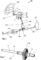
- FIG. 1 a schematic representation of a motor vehicle steering system 100 is shown, wherein a driver via a steering wheel 102 can introduce a corresponding torque as a steering command in a steering shaft 1.
- the torque is then transmitted via the steering shaft 1 to a steering pinion 104, which meshes with a rack 106, which in turn transmits via corresponding tie rods 108 the predetermined steering angle to the steerable wheels 110 of the motor vehicle.
- An electric and / or hydraulic power assist may be provided in the form of the auxiliary power assist 112 coupled to the steering shaft 1, the assist power assist 114 coupled to the sprocket 104, and / or the assist power assist 116 coupled to the rack 106.
- the respective assist power 112, 114 or 116 inputs an assist torque to the steering shaft 1, the steering gear 104 and / or an assisting force to the rack 106, thereby assisting the driver in steering work.
- the three different in the FIG. 1 shown auxiliary power supports 112, 114 and 116 show possible positions for their arrangement.
- the assist torque or the assist force to be applied to assist the driver by means of the respective assist power 112, 114 or 116 is determined in consideration of an input torque detected by a torque sensor 118.
- the auxiliary torque or the auxiliary power can be introduced with the power assist 112, 114, 116, an additional steering angle in the steering system, which sums up with the applied by the driver via the steering wheel 102 steering angle.
- the steering shaft 1 has an input shaft 10 connected to the steering wheel 102 and an output shaft 12 connected to the teeth 106 via the steering pinion 104.
- the input shaft 10 and the output shaft 12 are torsionally elastic over a in the FIG. 1 unrecognizable torsion bar coupled together.
- a torque input to the input shaft 10 from a driver through the steering wheel 102 always results in relative rotation of the input shaft 10 with respect to the output shaft 12 when the output shaft 12 does not rotate in exact synchronism with the input shaft 10.
- This relative rotation between the input shaft 10 and output shaft 12 can be measured, for example, via a rotation angle sensor and be determined accordingly due to the known torsional stiffness of the torsion bar in a corresponding input torque relative to the output shaft.
- the torque sensor 118 is formed.
- a torque sensor 118 is known in principle and can be realized for example in the form of a rotary slide valve, an electromagnetic or other measurement of the relative rotation.
- the torque sensor 118 can also be arranged alternatively at the position 118 ', in which case the aperture of the steering shaft 1 in the input shaft 10 and output shaft 12 and the torsionally flexible coupling via the torsion bar correspondingly present at a different position to from the relative rotation of the over the torsion bar the input shaft 10 coupled output shaft 12 to be able to determine a relative rotation and thus according to an input torque and / or an auxiliary power to be entered.
- the steering shaft 1 in the FIG. 1 further comprises at least one gimbal joint 120, by means of which the profile of the steering shaft 1 in the motor vehicle can be adapted to the spatial conditions.
- FIGS. 2 to 10 as well as 11 illustrated embodiments of the steering shaft 1 can be particularly well with the in FIG. 1 connect shown assembly of the torque sensor 118 in conjunction with the power steering assist coupled to the steering shaft 1 112.
- FIG. 11 shown embodiment of the steering shaft 1 is particularly well to use together with the arrangement of the torque sensor 118 'in conjunction with the coupled with the pinion 104 auxiliary power assistance 114 and coupled to the rack 106 auxiliary power assistance 116.
- FIG. 2 schematically shows a steering shaft 1 with an output shaft 12 designed as a first shaft part and an input shaft 10 designed as a second shaft part, wherein the range of the coincidence of the input shaft 10 with the output shaft 12 of the in FIG. 1 spanned torque sensor 118 is spanned.
- the input shaft 10 is arranged coaxially with respect to the output shaft 12 and with this moselastisch a in FIG. 2 not to be recognized, but connected internally extending torsion bar, the concrete structure of the steering shaft 1 in the FIGS. 3 to 5 is clarified.
- a worm gear 1120 is rotatably provided on the output shaft 12.
- On the worm gear 1120 can correspondingly an output of an electric motor or servomotor of the auxiliary power assistance 112 act.
- a hydraulic drive may be provided.
- the auxiliary power assistance 112 is therefore used to enter the torque detected by the torque sensor 118 for assisting the driver in the output shaft 12 and thus in all downstream of the output shaft 12 lying components of the motor vehicle steering 100.
- the input shaft 10 and the output shaft 12 are rotationally elastic connected to each other, so that the respective steering command, which the driver via the steering wheel 102 in the input shaft 10 is registered, in a support of the driver by the power assist 112, which acts on the worm gear 1120 and thus on the steering shaft 1 results.
- the torque sensor 118 is provided, which determines the relative rotation between the input shaft 10 and the output shaft 12 and the corresponding relative rotational angle between the input shaft 10 and output shaft 12 and on this basis the auxiliary torque 112 to be provided auxiliary torque can be determined.
- FIG. 3 1 is a schematic exploded view of the steering shaft 1, with the input shaft 10 and the output shaft 12 shown together with the worm gear 1120.
- the input shaft 10 has a receiving region 20 which serves to receive a complementary insertion region 22 of the output shaft 12. This is in the sectional view of FIG. 5 again particularly clearly seen, wherein the insertion portion 22 of the output shaft 12 is received in the receiving portion 20 of the input shaft 10 so that in principle the input shaft 10 with respect to the output shaft 12 can rotate freely, but at the same time is guided in the radial direction. A slight clearance exists between the receiving area 20 and the insertion area 22 in order to achieve a substantially frictionless rotation.
- a torsion bar 3 connects the input shaft 10 with the output shaft 12 torsionally elastic.
- This torsionally flexible connection of the input shaft 10 to the output shaft 12 is in FIG. 5 shown schematically in a sectional view.
- the torsion bar 3 has at its end facing the output shaft 12 a joining section 30 and at its end facing the input shaft 10 a joining section 32.
- the output shaft 12 facing the joining portion 30 of the torsion bar 3 is rotatably connected to the output shaft 12 in a joint receiving 40 of the output shaft 12.
- the input shaft 10 facing the joining portion 32 of the torsion bar 3 is rotatably connected to the input shaft 10 in a joint receiving 42 of the input shaft 10.
- the torsion bar 3 is received in a bore 28 in the output shaft 12 and extends from the mating receptacle 40 of the output shaft 12 through the bore 28 and through the open end 280 therethrough in the direction of the joining receptacle 42 of the input shaft 10th
- the torsion bar 3 has a bearing region 34 with a bearing receptacle 36, on which a bearing element 340 can be held such that, as can be seen, for example FIG. 5 shows that on the joining portion 30 on the output shaft 12 rotatably held torsion bar 3 can rotate freely relative to the output shaft 12 in the bore 28 of the output shaft 12.
- the torsion bar 3 is held by the bearing member 340 is substantially coaxial with the input shaft 10 and the output shaft 12. In this case, a possible misalignment between the input shaft 10 and the output shaft 12 is avoided.
- FIG. 4 schematically shows a mounting state of the steering shaft 1, in which the torsion bar 3 is already inserted into the bore 28 of the output shaft 12 and the joint portion 30 of the torsion bar 3 non-positively and positively connected to the joining receptacle 40 of the output shaft 12. Accordingly, only the other joining portion 32 of the torsion bar 3 projects out of the output shaft 12, so that in a subsequent assembly step the insertion portion 22 of the output shaft 12 can be inserted into the corresponding receiving area 20 of the input shaft 12, whereby the joint portion 32 of the torsion bar 3 in the corresponding joining receptacle 42 of the input shaft 10 is pressed.
- the input shaft 10 and the output shaft 12 in addition to the torsionally elastic connection via the torsion bar 3 are preferred connected via a loose fit so that a maximum value for the relative rotation of the input shaft 10 to the output shaft 12 and thus a maximum value for the rotation of the torsion bar 3 is given.
- a bearing element 340 is schematically shown at the reference A in the circular section, which is arranged in the bearing area 34 of the torsion bar 3 and which is arranged between the bearing receptacle 36 in the bearing area 34 of the torsion bar 3 and a bearing receptacle 26 of the output shaft 12.
- the bearing receptacle 26 is provided on the inner circumferential surface of the bore 28 in the output shaft 12.
- the bearing receiver 26 is provided within the bore 28 in the immediate vicinity of the open end 280 of the output shaft 12.
- the bearing member 340 is provided in the bearing portion 34 of the torsion bar 3 to hold the torsion bar 3 substantially coaxial with the output shaft 12 in the bore 28 and correspondingly skew between the input shaft 10, the output shaft 12 and the torsion bar 3 avoid in order to minimize a possible distortion of the torque measurement and / or possible noise.
- the bearing member 340 includes in the embodiments, a biasing member which can build a radial biasing force between the output shaft 12 and the torsion bar 3 and in this way can hold the torsion bar 3 coaxial with the output shaft 12.
- FIGS. 6 to 10 different embodiments of the biasing element comprehensive bearing element 340 are shown.
- FIG. 6 is the designated by the reference numeral A section of the FIG. 5 shown in a first embodiment.
- the bearing member 340 comprises circumferentially arranged rolling elements 342 which are held in a spring rolling bearing ring 344 forming the biasing member.
- the rolling bearing ring 344 is supported directly on the bearing seat 26 of the output shaft 12.
- the rolling elements 342 roll directly on the bearing receptacle 36 of the torsion bar 3.
- the biasing element in the form of the rolling bearing ring 344 acts accordingly indirectly, namely on the rolling elements 342, on the torsion bar 3.
- the roller bearing ring 344 is formed here as a rolling bearing outer ring.
- Trained as a biasing element bearing ring 344 is preferably in the form of a sheet metal part, for example in the form of a sheet-metal sleeve ring, which is constricted in its central region formed.
- the thickness of the sheet is designed so that the rolling bearing ring 344 has elastic properties and can exert a corresponding bias.
- the rolling elements 342 may be made of plastic or may be formed as a steel body - especially in the formation of a radially biased needle bearing. In a development, the rolling elements can also be made elastic, for example as thin, hollow steel rollers.
- the rolling bearing ring 344 has in the embodiment shown a waisted shape and forms a corresponding resilient part, which biases the rolling elements 342 against the bearing seat 36 of the torsion bar 3.
- the rolling bearings 342 are able to always follow the outer contours of the bearing receptacle 36 of the torsion bar 3. Accordingly, the tolerance requirements for the bearing receptacle 36 as well as the tolerance requirements for the bearing receptacle 26 compared to the use of a conventional roller bearing or needle bearing can be reduced, at the same time the Klappedrink or the tendency to emit noise is reduced.
- the bearing element 340 by rolling elements 342 and a biasing member in the form of a rolling bearing ring 344 is shown.
- the rolling bearing ring 344 is supported here on the bearing receptacle 36 of the torsion bar 3 and the rolling elements 342 roll on the bearing seat 26, so that here again a radial bias between the bearing receptacle 26 of the output shaft 12 and the bearing receptacle 36 of the torsion bar 3 is formed, which therefor ensures that the torsion bar 3 is held coaxial with the output shaft 12.
- the rolling bearing ring 344 is designed here as a rolling bearing inner ring.
- the rolling elements 342 can better follow the contours of the bearing receptacle 26 due to the applied pretension, so that a tilting tendency can be further reduced even with reduced tolerance requirements.
- the roller bearing ring 344 is formed waisted, so that it exerts a bias on the rolling elements 342 in the radial direction and correspondingly biases the rolling elements 342 on the bearing seat 26 of the output shaft 12 and the bearing seat 36 of the torsion bar 3.
- FIG. 8 is a schematic sectional view of a bearing element 340 shown in a further embodiment.
- the bearing element 340 is shown by a biasing element, which is in the form of a radially resilient slide bushing 346 shown.
- the radially resilient slide bushing 346 is formed waisted and is accordingly able to form a radial bias.
- the sliding bush 346 is supported both on the bearing receptacle 26 and on the bearing receptacle 36, so that the bearing element 340 directly transmits the preload.
- the bearing member 340 is correspondingly formed so that the biasing member 344 biases the torsion bar 3 in the bore 28 radially such that the torsion bar 3 is held coaxially with the output shaft 12.
- FIG. 9 a further embodiment of the bearing element 340 is shown, in which in turn a biasing element in the form of a radially resilient sliding bush 346 is formed, which serves as a biasing element accordingly.
- the sliding bush 346 is formed waisted to apply the corresponding biasing force can.
- Sliding bushing 346 shown is in a reverse orientation than that shown in FIG. 8 shown orientation, arranged between the bearing areas 26 and 36.
- FIG. 10 a further schematic sectional view is shown, in which the bearing element 340 is again formed as a biasing element, wherein the bearing element 340 is formed here by an elastic plastic sleeve 348, which a bias between the bearing seat 26 of the output shaft 12 and the bearing seat 36 of the torsion bar 3 in radial Providing direction.
- the biasing elements 346, 344 as shown for example in the FIGS. 6 . 7 . 8th and 9 are shown, may also be formed as a plastic sleeve.
- FIG. 11 is a schematic perspective view of a steering shaft 1 shown in a further embodiment, which comprises an input shaft 10 and an output shaft 12 and which is intended, for example, together with the torque sensor 118 'of FIG. 1 to be used.
- the steering pinion 104 is then provided directly on the output shaft 12 and an auxiliary torque is applied directly to the steering rack 104 and / or by means of the auxiliary power assistance 116 directly to the rack 106 by means of the auxiliary power assistance 114.
- steering shaft 1 has internally substantially the same structure as in the different embodiments in the FIGS. 2 to 10 is shown.
Landscapes
- Engineering & Computer Science (AREA)
- Mechanical Engineering (AREA)
- Chemical & Material Sciences (AREA)
- Combustion & Propulsion (AREA)
- Transportation (AREA)
- General Engineering & Computer Science (AREA)
- Power Steering Mechanism (AREA)
- Steering Controls (AREA)
Priority Applications (1)
| Application Number | Priority Date | Filing Date | Title |
|---|---|---|---|
| PL15706477T PL3114010T3 (pl) | 2014-03-04 | 2015-02-25 | Wał kierowniczy dla układu kierowniczego pojazdu mechanicznego |
Applications Claiming Priority (2)
| Application Number | Priority Date | Filing Date | Title |
|---|---|---|---|
| DE201410102807 DE102014102807B3 (de) | 2014-03-04 | 2014-03-04 | Lenkwelle für eine Kraftfahrzeuglenkung |
| PCT/EP2015/053955 WO2015132106A1 (de) | 2014-03-04 | 2015-02-25 | Lenkwelle für eine kraftfahrzeuglenkung |
Publications (2)
| Publication Number | Publication Date |
|---|---|
| EP3114010A1 EP3114010A1 (de) | 2017-01-11 |
| EP3114010B1 true EP3114010B1 (de) | 2018-08-22 |
Family
ID=52589399
Family Applications (1)
| Application Number | Title | Priority Date | Filing Date |
|---|---|---|---|
| EP15706477.5A Active EP3114010B1 (de) | 2014-03-04 | 2015-02-25 | Lenkwelle für eine kraftfahrzeuglenkung |
Country Status (7)
| Country | Link |
|---|---|
| US (1) | US10137926B2 (pl) |
| EP (1) | EP3114010B1 (pl) |
| CN (1) | CN106103245B (pl) |
| DE (1) | DE102014102807B3 (pl) |
| ES (1) | ES2697334T3 (pl) |
| PL (1) | PL3114010T3 (pl) |
| WO (1) | WO2015132106A1 (pl) |
Families Citing this family (15)
| Publication number | Priority date | Publication date | Assignee | Title |
|---|---|---|---|---|
| DE102013109284B4 (de) * | 2013-08-27 | 2017-04-06 | Thyssenkrupp Presta Aktiengesellschaft | Lenkwelle für eine Kraftfahrzeuglenkung |
| DE102014102807B3 (de) * | 2014-03-04 | 2015-04-02 | Thyssenkrupp Presta Ag | Lenkwelle für eine Kraftfahrzeuglenkung |
| CN105829190B (zh) * | 2014-03-05 | 2018-03-16 | 日本精工株式会社 | 电动式助力转向装置及其组装方法 |
| FR3057310B1 (fr) * | 2016-10-11 | 2019-07-05 | Jtekt Europe | Palier amortisseur avec pre-charge axiale |
| CN106585705B (zh) * | 2016-12-06 | 2018-03-23 | 昌辉汽车转向系统(黄山)有限公司 | 一种汽车转向传感器安装结构 |
| US10844909B2 (en) | 2017-11-02 | 2020-11-24 | Steering Solutions Ip Holding Corporation | Electric power steering assembly |
| DE102018205606A1 (de) * | 2018-04-13 | 2019-10-17 | Robert Bosch Gmbh | Lenkgetriebe für ein Lenksystem eines Kraftfahrzeugs |
| DE102018124143A1 (de) * | 2018-09-28 | 2020-04-02 | Thyssenkrupp Ag | Lagervorrichtung, Verstellvorrichtung, verstellbare Lenksäule, Verfahren zum Herstellen einer Verstellvorrichtung |
| DE102019118675A1 (de) * | 2019-07-10 | 2021-01-14 | Thyssenkrupp Ag | Lenkwelle für eine elektromechanische Kraftfahrzeuglenkung mit einer Lageranordnung aufweisend ein Vorspannelement |
| US11511786B2 (en) | 2019-09-04 | 2022-11-29 | Steering Solutions Ip Holding Corporation | Rattle noise reducing electric power steering column assembly and method |
| DE102020119281B4 (de) | 2020-07-22 | 2026-05-07 | Knorr-Bremse Systeme für Nutzfahrzeuge GmbH | Wellenanordnung und Lenkgetriebe mit einer Wellenanordnung |
| CN112499525B (zh) * | 2020-12-07 | 2025-05-23 | 杭叉集团股份有限公司 | 电动平衡重式叉车及其电助力转向系统 |
| KR20230107969A (ko) * | 2022-01-10 | 2023-07-18 | 에이치엘만도 주식회사 | 전동식 파워 스티어링 장치(eps)의 조향축 연결 구조 |
| CN116062023B (zh) * | 2022-12-29 | 2024-11-15 | 博世汽车转向系统(济南)有限公司 | 转向系统及其电子动力转向辅助装置 |
| CN116161104A (zh) * | 2022-12-29 | 2023-05-26 | 博世汽车转向系统(济南)有限公司 | 转向系统及其电子动力转向辅助装置 |
Family Cites Families (17)
| Publication number | Priority date | Publication date | Assignee | Title |
|---|---|---|---|---|
| US4127080A (en) * | 1977-03-08 | 1978-11-28 | Lakiza Rostislav I | Tubular shaft of a marine line shafting |
| JPS59106368A (ja) * | 1982-12-09 | 1984-06-20 | Atsugi Motor Parts Co Ltd | 動力操向装置 |
| FR2642719B1 (fr) * | 1988-12-28 | 1993-12-31 | Bendix France Sa | Dispositif de commande de servodirection pour vehicules automobiles |
| DE4241531C1 (de) * | 1992-12-10 | 1994-06-23 | Daimler Benz Ag | Servosteuerung, insbesondere Servolenkung für Kraftfahrzeuge |
| US5727443A (en) * | 1994-11-28 | 1998-03-17 | A.E. Bishop & Associates Pty Limited | Method of balancing a hydraulic valve for a power steering gear |
| US5878832A (en) * | 1997-08-13 | 1999-03-09 | General Motors Corporation | Steering apparatus for motor vehicle |
| US6250334B1 (en) * | 1998-12-21 | 2001-06-26 | Ina Walzlager Schaeffler Ohg | Centering device for steering valves |
| DE19937282A1 (de) * | 1999-08-06 | 2001-02-08 | Schaeffler Waelzlager Ohg | Zentriereinrichtung, insbesondere für Lenkventile |
| US6296018B1 (en) * | 1999-08-30 | 2001-10-02 | Trw Inc. | Rack and pinion steering system |
| DE10003738A1 (de) * | 2000-01-28 | 2001-08-09 | Bosch Gmbh Robert | Drehmoment-Erfassungseinrichtung an einer sich drehenden oder ruhenden Vorrichtung, insbesondere an der Welle einer Fahrzeuglenkung |
| DE10010837B4 (de) * | 2000-03-09 | 2011-02-17 | Thyssenkrupp Presta Steertec Gmbh | Drehschieber mit Drehstabbefestigung ohne spanende Bearbeitung |
| DE10200609A1 (de) * | 2002-01-10 | 2003-07-24 | Ina Schaeffler Kg | Elektrisch unterstützte Hilfskraftlenkung für Kraftfahrzeuge |
| CN2725145Y (zh) * | 2004-08-18 | 2005-09-14 | 中国南方航空动力机械公司 | 汽车助力转向器 |
| DE102010039125A1 (de) * | 2010-08-10 | 2012-02-16 | Zf Lenksysteme Gmbh | Lenkwelle für eine Lenkeinrichtung in einem Fahrzeug |
| CN202038363U (zh) * | 2011-01-14 | 2011-11-16 | 浙江师范大学 | 一种液压助力转向器转阀结构 |
| DE102013219883A1 (de) * | 2013-10-01 | 2015-04-02 | Schaeffler Technologies Gmbh & Co. Kg | Wälzlager |
| DE102014102807B3 (de) * | 2014-03-04 | 2015-04-02 | Thyssenkrupp Presta Ag | Lenkwelle für eine Kraftfahrzeuglenkung |
-
2014
- 2014-03-04 DE DE201410102807 patent/DE102014102807B3/de not_active Expired - Fee Related
-
2015
- 2015-02-25 PL PL15706477T patent/PL3114010T3/pl unknown
- 2015-02-25 US US15/122,604 patent/US10137926B2/en active Active
- 2015-02-25 WO PCT/EP2015/053955 patent/WO2015132106A1/de not_active Ceased
- 2015-02-25 CN CN201580011322.9A patent/CN106103245B/zh active Active
- 2015-02-25 EP EP15706477.5A patent/EP3114010B1/de active Active
- 2015-02-25 ES ES15706477T patent/ES2697334T3/es active Active
Non-Patent Citations (1)
| Title |
|---|
| None * |
Also Published As
| Publication number | Publication date |
|---|---|
| US20170072988A1 (en) | 2017-03-16 |
| WO2015132106A9 (de) | 2016-09-22 |
| PL3114010T3 (pl) | 2019-02-28 |
| WO2015132106A1 (de) | 2015-09-11 |
| US10137926B2 (en) | 2018-11-27 |
| EP3114010A1 (de) | 2017-01-11 |
| CN106103245A (zh) | 2016-11-09 |
| DE102014102807B3 (de) | 2015-04-02 |
| ES2697334T3 (es) | 2019-01-23 |
| CN106103245B (zh) | 2019-08-09 |
Similar Documents
| Publication | Publication Date | Title |
|---|---|---|
| EP3114010B1 (de) | Lenkwelle für eine kraftfahrzeuglenkung | |
| EP3137365B1 (de) | Vorrichtung zum aufbringen einer hilfskraft in einer kraftfahrzeuglenkung | |
| EP3134308B1 (de) | Lenkwelle für ein kraftfahrzeug | |
| EP3038880B1 (de) | Lenkwelle für eine kraftfahrzeuglenkung | |
| EP2233381B1 (de) | Kostengünstiges Zahnstangenlenkgetriebe | |
| DE102014110306A1 (de) | Elektromechanische Servolenkung | |
| EP3253644B1 (de) | Vorrichtung zur einbringung eines hilfsdrehmoments in eine lenkwelle und elektro-mechanische hilfskraftlenkung | |
| DE102018129061A1 (de) | Verfahren zur Herstellung von elektromotorisch unterstützten Lenksystemen sowie elektromotorisch unterstütztes Lenksystem | |
| DE112020005479T5 (de) | Elektrische (steer-by-wire-) lenkvorrichtung | |
| DE10200609A1 (de) | Elektrisch unterstützte Hilfskraftlenkung für Kraftfahrzeuge | |
| WO2015169556A1 (de) | Lenkwelle für eine kraftfahrzeuglenkung | |
| DE102018100318B4 (de) | Lenksäule für ein fahrzeug | |
| EP2731850B1 (de) | Lenkritzel für ein lenksystem sowie verfahren zu dessen herstellung | |
| DE102018130734A1 (de) | Kugelmutterbaugruppe für eine servolenkungbaugruppeeines fahrzeugs | |
| EP4043319B1 (de) | Lenksystem für ein kraftfahrzeug und verfahren zum montieren eines lenksystems für ein kraftfahrzeug | |
| WO2016139214A1 (de) | Einteilige eingangswelle | |
| WO2019048123A1 (de) | Festlager für ein lenkgetriebe und verfahren zur herstellung des festlagers | |
| EP4377582B1 (de) | Gelenkkopf, kreuzgelenk, lenkwelle und lenksystem für ein kraftfahrzeug | |
| DE102009046141A1 (de) | Lenkgetriebe für ein Lenksystem und Verfahren zur Montage desselben | |
| EP3055188B1 (de) | Lenkwelle für eine kraftfahrzeuglenkung | |
| EP1375303B1 (de) | Hydrolenkung für Kraftfahrzeuge | |
| WO2019234013A1 (de) | Elektromechanische kraftfahrzeuglenkung aufweisend mittels eines kegelförmigen pressverbands verbundene gehäuseteile | |
| WO2019086170A1 (de) | Lenksystem | |
| BE1031445A1 (de) | Aktuatorstange für einen Lenkaktuator eines Kraftfahrzeugs, Lenkaktuator für ein Lenksystem eines Kraftfahrzeugs, und Steer-by-Wire-Lenksystem für ein Kraftfahrzeug | |
| DE102015212548A1 (de) | Lenkwelle für eine Lenksäule eines Kraftfahrzeugs, Lenksäule für ein Kraftfahrzeug und Verfahren zur Herstellung einer Lenkwelle |
Legal Events
| Date | Code | Title | Description |
|---|---|---|---|
| PUAI | Public reference made under article 153(3) epc to a published international application that has entered the european phase |
Free format text: ORIGINAL CODE: 0009012 |
|
| STAA | Information on the status of an ep patent application or granted ep patent |
Free format text: STATUS: REQUEST FOR EXAMINATION WAS MADE |
|
| 17P | Request for examination filed |
Effective date: 20160927 |
|
| AK | Designated contracting states |
Kind code of ref document: A1 Designated state(s): AL AT BE BG CH CY CZ DE DK EE ES FI FR GB GR HR HU IE IS IT LI LT LU LV MC MK MT NL NO PL PT RO RS SE SI SK SM TR |
|
| AX | Request for extension of the european patent |
Extension state: BA ME |
|
| DAX | Request for extension of the european patent (deleted) | ||
| RAP1 | Party data changed (applicant data changed or rights of an application transferred) |
Owner name: THYSSENKRUPP PRESTA AG Owner name: THYSSENKRUPP AG |
|
| REG | Reference to a national code |
Ref country code: DE Ref legal event code: R079 Ref document number: 502015005546 Country of ref document: DE Free format text: PREVIOUS MAIN CLASS: B62D0006100000 Ipc: B62D0005040000 |
|
| RIC1 | Information provided on ipc code assigned before grant |
Ipc: F16D 3/10 20060101ALI20180227BHEP Ipc: B62D 5/04 20060101AFI20180227BHEP Ipc: B62D 6/10 20060101ALI20180227BHEP Ipc: B62D 5/083 20060101ALI20180227BHEP |
|
| GRAP | Despatch of communication of intention to grant a patent |
Free format text: ORIGINAL CODE: EPIDOSNIGR1 |
|
| STAA | Information on the status of an ep patent application or granted ep patent |
Free format text: STATUS: GRANT OF PATENT IS INTENDED |
|
| INTG | Intention to grant announced |
Effective date: 20180406 |
|
| GRAS | Grant fee paid |
Free format text: ORIGINAL CODE: EPIDOSNIGR3 |
|
| GRAA | (expected) grant |
Free format text: ORIGINAL CODE: 0009210 |
|
| STAA | Information on the status of an ep patent application or granted ep patent |
Free format text: STATUS: THE PATENT HAS BEEN GRANTED |
|
| AK | Designated contracting states |
Kind code of ref document: B1 Designated state(s): AL AT BE BG CH CY CZ DE DK EE ES FI FR GB GR HR HU IE IS IT LI LT LU LV MC MK MT NL NO PL PT RO RS SE SI SK SM TR |
|
| REG | Reference to a national code |
Ref country code: GB Ref legal event code: FG4D Free format text: NOT ENGLISH |
|
| REG | Reference to a national code |
Ref country code: CH Ref legal event code: EP |
|
| REG | Reference to a national code |
Ref country code: AT Ref legal event code: REF Ref document number: 1032122 Country of ref document: AT Kind code of ref document: T Effective date: 20180915 |
|
| REG | Reference to a national code |
Ref country code: IE Ref legal event code: FG4D Free format text: LANGUAGE OF EP DOCUMENT: GERMAN |
|
| REG | Reference to a national code |
Ref country code: DE Ref legal event code: R096 Ref document number: 502015005546 Country of ref document: DE |
|
| REG | Reference to a national code |
Ref country code: NL Ref legal event code: MP Effective date: 20180822 |
|
| REG | Reference to a national code |
Ref country code: LT Ref legal event code: MG4D |
|
| REG | Reference to a national code |
Ref country code: ES Ref legal event code: FG2A Ref document number: 2697334 Country of ref document: ES Kind code of ref document: T3 Effective date: 20190123 |
|
| PG25 | Lapsed in a contracting state [announced via postgrant information from national office to epo] |
Ref country code: SE Free format text: LAPSE BECAUSE OF FAILURE TO SUBMIT A TRANSLATION OF THE DESCRIPTION OR TO PAY THE FEE WITHIN THE PRESCRIBED TIME-LIMIT Effective date: 20180822 Ref country code: BG Free format text: LAPSE BECAUSE OF FAILURE TO SUBMIT A TRANSLATION OF THE DESCRIPTION OR TO PAY THE FEE WITHIN THE PRESCRIBED TIME-LIMIT Effective date: 20181122 Ref country code: NL Free format text: LAPSE BECAUSE OF FAILURE TO SUBMIT A TRANSLATION OF THE DESCRIPTION OR TO PAY THE FEE WITHIN THE PRESCRIBED TIME-LIMIT Effective date: 20180822 Ref country code: IS Free format text: LAPSE BECAUSE OF FAILURE TO SUBMIT A TRANSLATION OF THE DESCRIPTION OR TO PAY THE FEE WITHIN THE PRESCRIBED TIME-LIMIT Effective date: 20181222 Ref country code: NO Free format text: LAPSE BECAUSE OF FAILURE TO SUBMIT A TRANSLATION OF THE DESCRIPTION OR TO PAY THE FEE WITHIN THE PRESCRIBED TIME-LIMIT Effective date: 20181122 Ref country code: FI Free format text: LAPSE BECAUSE OF FAILURE TO SUBMIT A TRANSLATION OF THE DESCRIPTION OR TO PAY THE FEE WITHIN THE PRESCRIBED TIME-LIMIT Effective date: 20180822 Ref country code: RS Free format text: LAPSE BECAUSE OF FAILURE TO SUBMIT A TRANSLATION OF THE DESCRIPTION OR TO PAY THE FEE WITHIN THE PRESCRIBED TIME-LIMIT Effective date: 20180822 Ref country code: GR Free format text: LAPSE BECAUSE OF FAILURE TO SUBMIT A TRANSLATION OF THE DESCRIPTION OR TO PAY THE FEE WITHIN THE PRESCRIBED TIME-LIMIT Effective date: 20181123 Ref country code: LT Free format text: LAPSE BECAUSE OF FAILURE TO SUBMIT A TRANSLATION OF THE DESCRIPTION OR TO PAY THE FEE WITHIN THE PRESCRIBED TIME-LIMIT Effective date: 20180822 |
|
| PG25 | Lapsed in a contracting state [announced via postgrant information from national office to epo] |
Ref country code: LV Free format text: LAPSE BECAUSE OF FAILURE TO SUBMIT A TRANSLATION OF THE DESCRIPTION OR TO PAY THE FEE WITHIN THE PRESCRIBED TIME-LIMIT Effective date: 20180822 Ref country code: HR Free format text: LAPSE BECAUSE OF FAILURE TO SUBMIT A TRANSLATION OF THE DESCRIPTION OR TO PAY THE FEE WITHIN THE PRESCRIBED TIME-LIMIT Effective date: 20180822 Ref country code: AL Free format text: LAPSE BECAUSE OF FAILURE TO SUBMIT A TRANSLATION OF THE DESCRIPTION OR TO PAY THE FEE WITHIN THE PRESCRIBED TIME-LIMIT Effective date: 20180822 |
|
| PG25 | Lapsed in a contracting state [announced via postgrant information from national office to epo] |
Ref country code: RO Free format text: LAPSE BECAUSE OF FAILURE TO SUBMIT A TRANSLATION OF THE DESCRIPTION OR TO PAY THE FEE WITHIN THE PRESCRIBED TIME-LIMIT Effective date: 20180822 Ref country code: EE Free format text: LAPSE BECAUSE OF FAILURE TO SUBMIT A TRANSLATION OF THE DESCRIPTION OR TO PAY THE FEE WITHIN THE PRESCRIBED TIME-LIMIT Effective date: 20180822 |
|
| REG | Reference to a national code |
Ref country code: DE Ref legal event code: R097 Ref document number: 502015005546 Country of ref document: DE |
|
| PG25 | Lapsed in a contracting state [announced via postgrant information from national office to epo] |
Ref country code: SK Free format text: LAPSE BECAUSE OF FAILURE TO SUBMIT A TRANSLATION OF THE DESCRIPTION OR TO PAY THE FEE WITHIN THE PRESCRIBED TIME-LIMIT Effective date: 20180822 Ref country code: SM Free format text: LAPSE BECAUSE OF FAILURE TO SUBMIT A TRANSLATION OF THE DESCRIPTION OR TO PAY THE FEE WITHIN THE PRESCRIBED TIME-LIMIT Effective date: 20180822 Ref country code: DK Free format text: LAPSE BECAUSE OF FAILURE TO SUBMIT A TRANSLATION OF THE DESCRIPTION OR TO PAY THE FEE WITHIN THE PRESCRIBED TIME-LIMIT Effective date: 20180822 |
|
| PLBE | No opposition filed within time limit |
Free format text: ORIGINAL CODE: 0009261 |
|
| STAA | Information on the status of an ep patent application or granted ep patent |
Free format text: STATUS: NO OPPOSITION FILED WITHIN TIME LIMIT |
|
| 26N | No opposition filed |
Effective date: 20190523 |
|
| PG25 | Lapsed in a contracting state [announced via postgrant information from national office to epo] |
Ref country code: SI Free format text: LAPSE BECAUSE OF FAILURE TO SUBMIT A TRANSLATION OF THE DESCRIPTION OR TO PAY THE FEE WITHIN THE PRESCRIBED TIME-LIMIT Effective date: 20180822 |
|
| REG | Reference to a national code |
Ref country code: CH Ref legal event code: PL |
|
| PG25 | Lapsed in a contracting state [announced via postgrant information from national office to epo] |
Ref country code: MC Free format text: LAPSE BECAUSE OF FAILURE TO SUBMIT A TRANSLATION OF THE DESCRIPTION OR TO PAY THE FEE WITHIN THE PRESCRIBED TIME-LIMIT Effective date: 20180822 Ref country code: LU Free format text: LAPSE BECAUSE OF NON-PAYMENT OF DUE FEES Effective date: 20190225 |
|
| REG | Reference to a national code |
Ref country code: BE Ref legal event code: MM Effective date: 20190228 |
|
| REG | Reference to a national code |
Ref country code: IE Ref legal event code: MM4A |
|
| PG25 | Lapsed in a contracting state [announced via postgrant information from national office to epo] |
Ref country code: LI Free format text: LAPSE BECAUSE OF NON-PAYMENT OF DUE FEES Effective date: 20190228 Ref country code: CH Free format text: LAPSE BECAUSE OF NON-PAYMENT OF DUE FEES Effective date: 20190228 |
|
| PG25 | Lapsed in a contracting state [announced via postgrant information from national office to epo] |
Ref country code: IE Free format text: LAPSE BECAUSE OF NON-PAYMENT OF DUE FEES Effective date: 20190225 |
|
| PG25 | Lapsed in a contracting state [announced via postgrant information from national office to epo] |
Ref country code: BE Free format text: LAPSE BECAUSE OF NON-PAYMENT OF DUE FEES Effective date: 20190228 |
|
| PG25 | Lapsed in a contracting state [announced via postgrant information from national office to epo] |
Ref country code: TR Free format text: LAPSE BECAUSE OF FAILURE TO SUBMIT A TRANSLATION OF THE DESCRIPTION OR TO PAY THE FEE WITHIN THE PRESCRIBED TIME-LIMIT Effective date: 20180822 |
|
| PG25 | Lapsed in a contracting state [announced via postgrant information from national office to epo] |
Ref country code: PT Free format text: LAPSE BECAUSE OF FAILURE TO SUBMIT A TRANSLATION OF THE DESCRIPTION OR TO PAY THE FEE WITHIN THE PRESCRIBED TIME-LIMIT Effective date: 20181222 Ref country code: MT Free format text: LAPSE BECAUSE OF FAILURE TO SUBMIT A TRANSLATION OF THE DESCRIPTION OR TO PAY THE FEE WITHIN THE PRESCRIBED TIME-LIMIT Effective date: 20180822 |
|
| REG | Reference to a national code |
Ref country code: AT Ref legal event code: MM01 Ref document number: 1032122 Country of ref document: AT Kind code of ref document: T Effective date: 20200225 |
|
| PG25 | Lapsed in a contracting state [announced via postgrant information from national office to epo] |
Ref country code: CY Free format text: LAPSE BECAUSE OF FAILURE TO SUBMIT A TRANSLATION OF THE DESCRIPTION OR TO PAY THE FEE WITHIN THE PRESCRIBED TIME-LIMIT Effective date: 20180822 Ref country code: AT Free format text: LAPSE BECAUSE OF NON-PAYMENT OF DUE FEES Effective date: 20200225 |
|
| PG25 | Lapsed in a contracting state [announced via postgrant information from national office to epo] |
Ref country code: HU Free format text: LAPSE BECAUSE OF FAILURE TO SUBMIT A TRANSLATION OF THE DESCRIPTION OR TO PAY THE FEE WITHIN THE PRESCRIBED TIME-LIMIT; INVALID AB INITIO Effective date: 20150225 |
|
| REG | Reference to a national code |
Ref country code: DE Ref legal event code: R081 Ref document number: 502015005546 Country of ref document: DE Owner name: THYSSENKRUPP PRESTA AKTIENGESELLSCHAFT, LI Free format text: FORMER OWNERS: THYSSENKRUPP AG, 45143 ESSEN, DE; THYSSENKRUPP PRESTA AG, ESCHEN, LI Ref country code: DE Ref legal event code: R081 Ref document number: 502015005546 Country of ref document: DE Owner name: THYSSENKRUPP AG, DE Free format text: FORMER OWNERS: THYSSENKRUPP AG, 45143 ESSEN, DE; THYSSENKRUPP PRESTA AG, ESCHEN, LI |
|
| PGFP | Annual fee paid to national office [announced via postgrant information from national office to epo] |
Ref country code: PL Payment date: 20220221 Year of fee payment: 8 Ref country code: IT Payment date: 20220218 Year of fee payment: 8 Ref country code: CZ Payment date: 20220224 Year of fee payment: 8 |
|
| PG25 | Lapsed in a contracting state [announced via postgrant information from national office to epo] |
Ref country code: MK Free format text: LAPSE BECAUSE OF FAILURE TO SUBMIT A TRANSLATION OF THE DESCRIPTION OR TO PAY THE FEE WITHIN THE PRESCRIBED TIME-LIMIT Effective date: 20180822 |
|
| PGFP | Annual fee paid to national office [announced via postgrant information from national office to epo] |
Ref country code: ES Payment date: 20220426 Year of fee payment: 8 |
|
| REG | Reference to a national code |
Ref country code: DE Ref legal event code: R084 Ref document number: 502015005546 Country of ref document: DE |
|
| PGFP | Annual fee paid to national office [announced via postgrant information from national office to epo] |
Ref country code: FR Payment date: 20230221 Year of fee payment: 9 |
|
| PGFP | Annual fee paid to national office [announced via postgrant information from national office to epo] |
Ref country code: GB Payment date: 20230221 Year of fee payment: 9 |
|
| PG25 | Lapsed in a contracting state [announced via postgrant information from national office to epo] |
Ref country code: CZ Free format text: LAPSE BECAUSE OF NON-PAYMENT OF DUE FEES Effective date: 20230225 |
|
| PG25 | Lapsed in a contracting state [announced via postgrant information from national office to epo] |
Ref country code: IT Free format text: LAPSE BECAUSE OF NON-PAYMENT OF DUE FEES Effective date: 20230225 |
|
| PG25 | Lapsed in a contracting state [announced via postgrant information from national office to epo] |
Ref country code: ES Free format text: LAPSE BECAUSE OF NON-PAYMENT OF DUE FEES Effective date: 20230226 |
|
| REG | Reference to a national code |
Ref country code: ES Ref legal event code: FD2A Effective date: 20240426 |
|
| PG25 | Lapsed in a contracting state [announced via postgrant information from national office to epo] |
Ref country code: ES Free format text: LAPSE BECAUSE OF NON-PAYMENT OF DUE FEES Effective date: 20230226 |
|
| PG25 | Lapsed in a contracting state [announced via postgrant information from national office to epo] |
Ref country code: PL Free format text: LAPSE BECAUSE OF NON-PAYMENT OF DUE FEES Effective date: 20230225 |
|
| PG25 | Lapsed in a contracting state [announced via postgrant information from national office to epo] |
Ref country code: PL Free format text: LAPSE BECAUSE OF NON-PAYMENT OF DUE FEES Effective date: 20230225 |
|
| GBPC | Gb: european patent ceased through non-payment of renewal fee |
Effective date: 20240225 |
|
| PG25 | Lapsed in a contracting state [announced via postgrant information from national office to epo] |
Ref country code: GB Free format text: LAPSE BECAUSE OF NON-PAYMENT OF DUE FEES Effective date: 20240225 |
|
| PG25 | Lapsed in a contracting state [announced via postgrant information from national office to epo] |
Ref country code: FR Free format text: LAPSE BECAUSE OF NON-PAYMENT OF DUE FEES Effective date: 20240229 |
|
| PG25 | Lapsed in a contracting state [announced via postgrant information from national office to epo] |
Ref country code: GB Free format text: LAPSE BECAUSE OF NON-PAYMENT OF DUE FEES Effective date: 20240225 Ref country code: FR Free format text: LAPSE BECAUSE OF NON-PAYMENT OF DUE FEES Effective date: 20240229 |
|
| PGFP | Annual fee paid to national office [announced via postgrant information from national office to epo] |
Ref country code: DE Payment date: 20260218 Year of fee payment: 12 |