EP3112705B1 - Scharniervorrichtung zum öffnen und schliessen des deckels von büroausrüstung - Google Patents
Scharniervorrichtung zum öffnen und schliessen des deckels von büroausrüstung Download PDFInfo
- Publication number
- EP3112705B1 EP3112705B1 EP15752166.7A EP15752166A EP3112705B1 EP 3112705 B1 EP3112705 B1 EP 3112705B1 EP 15752166 A EP15752166 A EP 15752166A EP 3112705 B1 EP3112705 B1 EP 3112705B1
- Authority
- EP
- European Patent Office
- Prior art keywords
- cam
- stop
- cover
- hinge
- rotational lever
- Prior art date
- Legal status (The legal status is an assumption and is not a legal conclusion. Google has not performed a legal analysis and makes no representation as to the accuracy of the status listed.)
- Active
Links
Images


Classifications
-
- E—FIXED CONSTRUCTIONS
- E05—LOCKS; KEYS; WINDOW OR DOOR FITTINGS; SAFES
- E05F—DEVICES FOR MOVING WINGS INTO OPEN OR CLOSED POSITION; CHECKS FOR WINGS; WING FITTINGS NOT OTHERWISE PROVIDED FOR, CONCERNED WITH THE FUNCTIONING OF THE WING
- E05F1/00—Closers or openers for wings, not otherwise provided for in this subclass
- E05F1/08—Closers or openers for wings, not otherwise provided for in this subclass spring-actuated, e.g. for horizontally sliding wings
- E05F1/10—Closers or openers for wings, not otherwise provided for in this subclass spring-actuated, e.g. for horizontally sliding wings for swinging wings, e.g. counterbalance
- E05F1/12—Mechanisms in the shape of hinges or pivots, operated by springs
- E05F1/1246—Mechanisms in the shape of hinges or pivots, operated by springs with a coil spring perpendicular to the pivot axis
- E05F1/1253—Mechanisms in the shape of hinges or pivots, operated by springs with a coil spring perpendicular to the pivot axis with a compression spring
- E05F1/1261—Mechanisms in the shape of hinges or pivots, operated by springs with a coil spring perpendicular to the pivot axis with a compression spring for counterbalancing
-
- E—FIXED CONSTRUCTIONS
- E05—LOCKS; KEYS; WINDOW OR DOOR FITTINGS; SAFES
- E05D—HINGES OR SUSPENSION DEVICES FOR DOORS, WINDOWS OR WINGS
- E05D11/00—Additional features or accessories of hinges
- E05D11/10—Devices for preventing movement between relatively-movable hinge parts
- E05D11/1028—Devices for preventing movement between relatively-movable hinge parts for maintaining the hinge in two or more positions, e.g. intermediate or fully open
- E05D11/105—Devices for preventing movement between relatively-movable hinge parts for maintaining the hinge in two or more positions, e.g. intermediate or fully open the maintaining means acting perpendicularly to the pivot axis
- E05D11/1064—Devices for preventing movement between relatively-movable hinge parts for maintaining the hinge in two or more positions, e.g. intermediate or fully open the maintaining means acting perpendicularly to the pivot axis with a coil spring perpendicular to the pivot axis
-
- E—FIXED CONSTRUCTIONS
- E05—LOCKS; KEYS; WINDOW OR DOOR FITTINGS; SAFES
- E05D—HINGES OR SUSPENSION DEVICES FOR DOORS, WINDOWS OR WINGS
- E05D3/00—Hinges with pins
- E05D3/02—Hinges with pins with one pin
-
- H—ELECTRICITY
- H04—ELECTRIC COMMUNICATION TECHNIQUE
- H04N—PICTORIAL COMMUNICATION, e.g. TELEVISION
- H04N1/00—Scanning, transmission or reproduction of documents or the like, e.g. facsimile transmission; Details thereof
- H04N1/00519—Constructional details not otherwise provided for, e.g. housings, covers
- H04N1/00551—Top covers or the like
- H04N1/00554—Latches or hinges therefor
-
- H—ELECTRICITY
- H04—ELECTRIC COMMUNICATION TECHNIQUE
- H04N—PICTORIAL COMMUNICATION, e.g. TELEVISION
- H04N1/00—Scanning, transmission or reproduction of documents or the like, e.g. facsimile transmission; Details thereof
- H04N1/00519—Constructional details not otherwise provided for, e.g. housings, covers
- H04N1/00557—Connection or assembly of components or elements
-
- H—ELECTRICITY
- H04—ELECTRIC COMMUNICATION TECHNIQUE
- H04N—PICTORIAL COMMUNICATION, e.g. TELEVISION
- H04N1/00—Scanning, transmission or reproduction of documents or the like, e.g. facsimile transmission; Details thereof
- H04N1/00519—Constructional details not otherwise provided for, e.g. housings, covers
- H04N1/00559—Mounting or support of components or elements
-
- E—FIXED CONSTRUCTIONS
- E05—LOCKS; KEYS; WINDOW OR DOOR FITTINGS; SAFES
- E05Y—INDEXING SCHEME ASSOCIATED WITH SUBCLASSES E05D AND E05F, RELATING TO CONSTRUCTION ELEMENTS, ELECTRIC CONTROL, POWER SUPPLY, POWER SIGNAL OR TRANSMISSION, USER INTERFACES, MOUNTING OR COUPLING, DETAILS, ACCESSORIES, AUXILIARY OPERATIONS NOT OTHERWISE PROVIDED FOR, APPLICATION THEREOF
- E05Y2201/00—Constructional elements; Accessories therefor
- E05Y2201/60—Suspension or transmission members; Accessories therefor
- E05Y2201/622—Suspension or transmission members elements
- E05Y2201/638—Cams; Ramps
-
- E—FIXED CONSTRUCTIONS
- E05—LOCKS; KEYS; WINDOW OR DOOR FITTINGS; SAFES
- E05Y—INDEXING SCHEME ASSOCIATED WITH SUBCLASSES E05D AND E05F, RELATING TO CONSTRUCTION ELEMENTS, ELECTRIC CONTROL, POWER SUPPLY, POWER SIGNAL OR TRANSMISSION, USER INTERFACES, MOUNTING OR COUPLING, DETAILS, ACCESSORIES, AUXILIARY OPERATIONS NOT OTHERWISE PROVIDED FOR, APPLICATION THEREOF
- E05Y2999/00—Subject-matter not otherwise provided for in this subclass
-
- H—ELECTRICITY
- H04—ELECTRIC COMMUNICATION TECHNIQUE
- H04N—PICTORIAL COMMUNICATION, e.g. TELEVISION
- H04N2201/00—Indexing scheme relating to scanning, transmission or reproduction of documents or the like, and to details thereof
- H04N2201/0077—Types of the still picture apparatus
- H04N2201/0094—Multifunctional device, i.e. a device capable of all of reading, reproducing, copying, facsimile transception, file transception
Definitions
- the present invention relates to a hinge device for opening and closing a cover of office equipment, and more particularly to a hinge device disposed at a cover which is rotatably opened and closed and having a multi-layered cam and a slider, so that a free stop section and a slow down section are performed in closing the cover, thereby reducing a noise in closing the cover and improving a sensibility of product.
- an office equipment such as a photocopier, a scanner, or a multifunction machine scans a document, then stores a scanned image as a data or prints the image on a printing paper.
- Such an office equipment includes a document glass disposed on a main body of the office equipment to scan the document, a cover to secure the document laid on the document glass, and a hinge apparatus connecting the cover and the main body of the office equipment.
- Fig. 1 and Fig. 2 show a conventional hinge device including a hinge body(1), a pressure device(2) and a hinge cam(3), disclosed in Korean Patent No. 10-0474425 .
- the above hinge body(1) is disposed to a main body(110) of the office equipment to be moved upward and downward, at an upper part a cover(120) and a secured hinge cam(3) are coupled each other by means of a hinge shaft.
- a pressure device(2) having a spring(2b) and a pusher(2a) is disposed within the hinge body(1), and the pusher(2a) is movably upward and downward inside of the hinge body(1) and a front end protruded to the outside is supported in a contact state with the hinge cam(3).
- the cover(120) of the conventional office equipment is closed in a state that a cam part of the hinge cam(3) presses the pusher(2a) of the pressure device(2) in the inner direction, in opening the cover(120), the hinge cam(3) and the pusher(2a) are in contact under a minimum pressure.
- the hinge body(1) is moved from the main body(110) of the office equipment to the upper part thereof, then a gap between the document glass and the cover(120) is increased.
- the above device has a configuration that the cover is closed in tight contact of the hinge cam and the pusher by pressing the pusher using the one cam part disposed at the hinge cam, and therefore, a slow down section in which all the process is slowly performed is provided only.
- a hinge device being performed a free stop function so as to configure freely an opening and closing angle of the cover within a certain range
- a free stop section is small, thereby generating a loud noise in closing the cover or causing user's injury.
- Patent Document 1 Korean Patent No. 10-0474425 , Hinge Apparatus for Cover of Office Machine (Patented on March 10, 2005)
- the present invention is derived to resolve the problems of the prior art as discussed above and has an object to provide a hinge device for opening and closing a cover of office equipment so as to improve a sensibility of product as well as reduce a noise in closing the cover and prevent injury, by enlarging a free stop section.
- Another object of the present invention is to provide a hinge device for opening and closing a cover of office equipment so as to reduce the number of required parts and a cost price, by configuring a multi-layered cam of one hinge cam and thereby performing a free stop function and a slow down function.
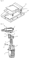
- a hinge device that comprises: a housing(10) which is disposed at a main body(110) of an office equipment and having a pair of hinge holes(11) on the upper portion thereof; a rotational lever(20) which is fixedly disposed at a cover(120) and having hinge holes(21) at the rear thereof and being provided with a hinge connection part(22) inserted into the upper portion inside the housing(10) at the lower portion of the rear thereof; a hinge shaft(30) being inserted into the hinge holes(11) of the housing(10) and the hinge holes(21) of the rotational lever(20) and combined with them and supporting rotation of the rotational lever(20) and the cover(120); a compression coil spring(40) being disposed inside the housing(10); a slider(50) being disposed on the upper portion inside the housing(10) and being elastically supported by the compression coil spring(40), and the upper end portion of which contacts with the lower end surface of
- stop cam(23a) which is a component of the multi-layered cam(23) of the rotational lever(20) is supported in contact with the stop surface (51a) of the supporting surface(51) and the down cams(23b) are supported in contact with the down surfaces(51b), so that the cover(120) fixedly connected to the rotational lever(20) is supported in an opened state.
- the stop cam(23a) which is the component of the multi-layered cam(23) of the rotational lever(20) is supported in contact with the stop surface (51a) of the supporting surface(51) so that the cover(120) fixedly connected to the rotational lever(20) is supported in an opened state. If the cover(120) is pressed to be in a closed state, a free stop section(A) where the stop cam(23a) presses the stop surface(51a) and moves the slider(50) toward the lower portion is arranged.
- a slow down section(B) where the down cams(23b) positioned at both sides of the stop cam(23a) press the down surfaces (51b) positioned at both sides of the supporting surface(51) and further move the slider(50) toward the lower portion is arranged.
- the rotational lever includes the multi-layered cam performing the free stop section and the slow down section, thereby reducing the number of required parts and a cost price.
- the free stop section is extended in opening and closing the cover, thereby improving a sensibility of product as well as reducing a noise in closing the cover or preventing user's injury.
- a hinge device for opening and closing a cover of office equipment is to provide with a hinge device disposed at a cover which is rotatably opened and closed and having a multi-layered cam and a slider, so that a free stop section and a slow down section are performed in closing the cover, thereby reducing a noise in closing the cover and improving a sensibility of product.
- a hinge device has a structure that comprises: a housing(10) which is disposed at a main body(110) of an office equipment with a document glass and a hinge connection part(22) to connect a cover(120) pressing the document disposed on the document glass to the main body(110) of the office equipment, disposed at the bottom of the cover, thereby interconnecting the housing(10) and the hinge connection part(22), using a hinge shaft(30).
- the housing(10) is fitted to one side of a mounting groove formed on the main body(110) of the office equipment to be moved upwardly and downwardly, and inside the body thereof, a receiving part is provided for receiving a compression coil spring(40) and a slider(50), and on the upper portion thereof, a pair of hinge holes(11) are positioned.
- a rotational lever(20) is fixedly disposed at the bottom of the cover(120), and at the rear thereof, hinge holes(21) are positioned, and at the lower portion of the rear thereof, the hinge connection part(22) located on the upper portion of the receiving part of the housing(10) is provided.
- the slider(50) being received in the receiving part of the housing(10) is elastically supported by the compression coil spring(40), and the upper end portion thereof is contacted with the lower end surface of the hinge connection part(22) of the rotational lever(20).
- the hinge shaft (30) is inserted into the hinge holes(11) of the housing(10) and the hinge holes(21) of the rotational lever(20) and combined with them and interconnects the rotational lever(20) and the cover(120), thereby supporting rotation of the cover(120).
- hinge connection part(22) of the rotational lever(20) is located at the front of hinge holes(21), so that a multi-layered cam(23) is provided to the lower end surface of the hinge connection part(22) and a supporting surface(51) is formed on the upper end surface of the slider(50).
- the multi-layered cam(23) of the rotational lever(20) has a stop cam(23a) in the center and at both sides thereof, down cams(23b) which locate at the rear than the surface of the stop cam(23a) and are lower than the stop cam (23a) .
- the supporting surface(51) of the slider(50) has an inclined plane that is getting higher toward the front, at the center of the front end, a stop surface(51a) which contacts with the stop cam(23a) of the rotational lever(20) and down surfaces(51b) which are protruded from both sides of the stop surface (51a) and contact with the down cams(23b) are provided.
- the stop cam(23a) which is the component of the multi-layered cam(23) of the rotational lever(20) is supported in contact with the stop surface (51a) of the supporting surface(51) and the down cams(23b) are supported in contact with the down surfaces(51b), so that the cover(120) fixedly connected to the rotational lever(20) is supported in an opened state.
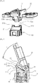
- the hinge device As described hereinabove, the hinge device according to the present invention, as shown in Fig. 5 , if the cover(120) connected to the rotational lever(20) is rotated in a certain angle in a closed state, from a maximum opening angle to a certain closing angle, a free stop section(A) is arranged where user can stop the rotational lever(20) and the cover(120) in any angle.
- the stop cam(23a) which is the component of the multi-layered cam(23) of the rotational lever(20) is supported in contact with the stop surface (51a) of the supporting surface(51) so that the cover(120) fixedly connected to the rotational lever(20) is supported in an opened state.
- the cover(120) is pressed to be in a closed state, the free stop section(A) where the stop cam(23a) presses the stop surface(51a) and moves the slider(50) toward the lower portion is arranged.
- a slow down section(B) where the cover(120) rotates by self load is arranged.
- a repulsive force of the compression coil spring (40) disposed inside the housing(10) is generated at the contact point of the supporting surface (51) in contact with the multi-layered cam(23) and a direction of force is acted in a vertical direction from the contact point, so that as shown in Fig. 5 , in case that the free stop section (A) where the maximum height area of the stop cam(23a) does not contact with the stop surface(51a), the supporting surface(51) of the slider(50) can support the certain opening angle by supporting the rear where the hinge holes(21) of the hinge connection part(22) are positioned under a compression force of the compression coil spring(40) .
- the maximum height area of the stop cam(23a) and the down cams(23b) which are the component of the multi-layered cam(23) are moved in contact with the stop surface(51a) disposed at the front of the supporting surface (51) and the down surfaces(51b) which are upwardly protruded from both sides of the stop surface (51a), the maximum height area of the stop cam(23a) is located at the rear than the maximum height area of the down cams(23b), so that the down cams (23b) and the down surfaces (51b) are located at the free stop section(A) with a certain space, as shown in Fig. 5 .
- the free stop section(A) after user rotates the cover(120) and the rotational lever(20) counterclockwise(closing direction) and the maximum height area of the stop cam(23a) of the hinge connection part(22) is left from the stop surface(51a) of the slider(50), as shown in Fig. 6 , the maximum height area of the down cams(23b) are moved in contact along the down surfaces(51b) and then the free stop section(A) is switched to the slow down section(B), even if user removes the pressure the cover(120) and the rotational lever(20) are rotated counterclockwise , so that the cover(120) is slowly closed.
- the multi-layered cam(23) of the hinge connection part(22) is located at the rear of the supporting surface(51) of the slider(50) and the slider(50) is lifted by the elastic force of the compression coil spring(40), and then the maximum height area of the down surfaces(51b) are supported in contact at the front of the maximum height area of the down cams(23b), so that the cover(120) is tightly contacted with the main body(110) of the office equipment.
Landscapes
- Engineering & Computer Science (AREA)
- Multimedia (AREA)
- Signal Processing (AREA)
- Mechanical Engineering (AREA)
- Pivots And Pivotal Connections (AREA)
- Holders For Sensitive Materials And Originals (AREA)
- Facsimiles In General (AREA)
- Hinges (AREA)
- Hinge Accessories (AREA)
Claims (4)
- Scharniervorrichtung zum Öffnen und Schließen einer Abdeckung von Büroausrüstung, umfassend:ein Gehäuse (10), das an einem Hauptkörper (110) einer Büroausrüstung angeordnet ist und ein Paar Scharnierlöcher (11) an seinem oberen Abschnitt hat;einen Drehhebel (20), der fest an einer Abdeckung (120) angeordnet ist und Scharnierlöcher (21) an seiner Rückseite aufweist und mit einem Scharnier-Verbindungsteil (22) an dem unteren Abschnitt seiner Rückseite versehen ist, welches in den oberen Abschnitt in dem Gehäuse (10) eingeführt ist;eine Scharnierwelle (30), die in die Scharnierlöcher (11) des Gehäuses (10) und die Scharnierlöcher (21) des Drehhebels (20) eingeführt und mit diesen verbunden ist und die Drehung des Drehhebels (20) und der Abdeckung (120) stützt;eine Spiralfeder (40), die in dem Gehäuse (10) angeordnet ist; undeinen Schieber (50), der an dem oberen Abschnitt in dem Gehäuse (10) angeordnet ist und elastisch von der Spiralfeder (40) gestützt wird und dessen oberer Endabschnitt mit der unteren Endfläche des Scharnier-Verbindungsteils (22) des Drehhebels (20) in Kontakt ist;wobei das Scharnier-Verbindungsteil (22) des Drehhebels (20) vorderseitig der Scharnierlöcher (21) angeordnet ist, so dass eine mehrschichtige Nocke (23) an der unteren Endfläche des Scharnier-Verbindungsteils (22) vorgesehen ist und eine Stützfläche (51) an der oberen Endfläche des Schiebers (50) gebildet ist,wobei die mehrschichtige Nocke (23) des Drehhebels (20) eine Anschlagnocke (23a) in der Mitte und beidseitig davon Abwärtsnocken (23b) hat, die weiter hinten als die Fläche der Anschlagnocke (23a) angeordnet und tiefer als die Anschlagnocke (23a) sind,wobei die Stützfläche (51) des Schiebers (50) eine geneigte Ebene, welche zur Vorderseite hin höher wird, in der Mitte des vorderen Endes eine Anschlagfläche (51a), welche mit der Anschlagnocke (23a) des Drehhebels (20) in Kontakt ist, und Abwärtsflächen (51b), die beidseitig der Anschlagfläche (51a) vorstehen und mit den Abwärtsnocken (23b) in Kontakt sind, aufweist.
- Scharniervorrichtung zum Öffnen und Schließen einer Abdeckung von Büroausrüstung nach Anspruch 1, wobei die Anschlagnocke (23a), welche die Komponente der mehrschichtigen Nocke (23) des Drehhebels (20) ist, in Kontakt mit der Anschlagfläche (51a) der Stützfläche (51) gestützt ist und die Abwärtsnocken (23b) in Kontakt mit den Abwärtsflächen (51b) gestützt sind, so dass die Abdeckung (120), welche fest mit dem Drehhebel (20) verbunden ist, in einem geöffneten Zustand gestützt ist.
- Scharniervorrichtung zum Öffnen und Schließen einer Abdeckung von Büroausrüstung nach Anspruch 2, wobei die Anschlagnocke (23a), welche die Komponente der mehrschichtigen Nocke (23) des Drehhebels (20) ist, in Kontakt mit der Anschlagfläche (51a) der Stützfläche (51) gestützt ist, so dass die Abdeckung (120), welche fest mit dem Drehhebel (20) verbunden ist, in einem geöffneten Zustand gestützt ist und, wenn die Abdeckung (120) in einen geschlossenen Zustand gedrückt wird, ein freier Anschlagabschnitt (A), wo die Anschlagnocke (23a) auf die Anschlagfläche (51a) drückt und den Schieber (50) in Richtung des unteren Abschnitts bewegt, angeordnet ist.
- Scharniervorrichtung zum Öffnen und Schließen einer Abdeckung von Büroausrüstung nach Anspruch 3, wobei, wenn die Anschlagnocke (23a), welche die Komponente der mehrschichtigen Nocke (23) des Drehhebels (20) ist, durch die Anschlagfläche (51a) der Stützfläche (51) gelangt, ein Abbremsabschnitt (B), wo die an beiden Seiten der Anschlagnocke (23a) angeordneten Abwärtsnocken (23b) auf die an beiden Seiten der Stützfläche (51) angeordneten Abwärtsfläche (51b) drücken und den Schieber (50) weiter in die untere Position bewegen, angeordnet ist.
Applications Claiming Priority (2)
| Application Number | Priority Date | Filing Date | Title |
|---|---|---|---|
| KR1020140021210A KR101481364B1 (ko) | 2014-02-24 | 2014-02-24 | 사무기기의 덮개 개폐용 힌지장치 |
| PCT/KR2015/001720 WO2015126207A1 (ko) | 2014-02-24 | 2015-02-23 | 사무기기의 덮개 개폐용 힌지장치 |
Publications (3)
| Publication Number | Publication Date |
|---|---|
| EP3112705A1 EP3112705A1 (de) | 2017-01-04 |
| EP3112705A4 EP3112705A4 (de) | 2017-12-20 |
| EP3112705B1 true EP3112705B1 (de) | 2018-12-12 |
Family
ID=52588373
Family Applications (1)
| Application Number | Title | Priority Date | Filing Date |
|---|---|---|---|
| EP15752166.7A Active EP3112705B1 (de) | 2014-02-24 | 2015-02-23 | Scharniervorrichtung zum öffnen und schliessen des deckels von büroausrüstung |
Country Status (7)
| Country | Link |
|---|---|
| US (1) | US9803409B2 (de) |
| EP (1) | EP3112705B1 (de) |
| JP (1) | JP6216465B2 (de) |
| KR (1) | KR101481364B1 (de) |
| CN (1) | CN106030130B (de) |
| TW (1) | TWI565885B (de) |
| WO (1) | WO2015126207A1 (de) |
Families Citing this family (14)
| Publication number | Priority date | Publication date | Assignee | Title |
|---|---|---|---|---|
| JP6710887B2 (ja) * | 2015-08-25 | 2020-06-17 | 下西技研工業株式会社 | ヒンジ |
| US10906733B2 (en) | 2017-11-13 | 2021-02-02 | HFG Corporate Limited | Safety latch for a mud skip |
| WO2019117939A1 (en) * | 2017-12-15 | 2019-06-20 | Hewlett-Packard Development Company, L.P. | Hinge connectors with rotation control units |
| JP7134470B2 (ja) * | 2018-06-26 | 2022-09-12 | 株式会社ナチュラレーザ・ワン | ヒンジ並びにこのヒンジを用いた各種機器 |
| WO2020093348A1 (en) * | 2018-11-09 | 2020-05-14 | Hewlett-Packard Development Company, L.P. | Hinge assembly |
| CN210041943U (zh) | 2019-07-10 | 2020-02-07 | 金宝电子工业股份有限公司 | 事务机器及枢纽结构 |
| US11021834B2 (en) * | 2019-07-12 | 2021-06-01 | Whirlpool Corporation | Laundry treating appliance having a hinge assembly |
| CN110313844B (zh) * | 2019-08-21 | 2024-07-16 | 无锡市惠昌烧烤炉科技有限公司 | 烧烤炉阻尼铰链 |
| WO2021039254A1 (ja) | 2019-08-30 | 2021-03-04 | スガツネ工業株式会社 | 1軸ヒンジ |
| WO2021196156A1 (en) * | 2020-04-03 | 2021-10-07 | Hewlett-Packard Development Company, L.P. | Hinge sliders |
| JP7485341B2 (ja) * | 2020-05-15 | 2024-05-16 | 株式会社ナチュラレーザ・ワン | ヒンジ装置並びにこのヒンジ装置を備えた各種機器 |
| JP7594277B2 (ja) * | 2020-11-27 | 2024-12-04 | 株式会社ナチュラレーザ・ワン | ヒンジ並びにこのヒンジを用いた事務機器 |
| US11809238B2 (en) * | 2021-05-11 | 2023-11-07 | Microsoft Technology Licensing, Llc | Systems and methods for electronic devices with integrated support |
| JP2023019067A (ja) * | 2021-07-28 | 2023-02-09 | 株式会社ナチュラレーザ・ワン | ヒンジ並びにこのヒンジを用いた事務機器 |
Family Cites Families (17)
| Publication number | Priority date | Publication date | Assignee | Title |
|---|---|---|---|---|
| US4424606A (en) * | 1981-08-10 | 1984-01-10 | Katoh Electrical Machinery Co. Ltd. | Hinge for opening and closing a dust cover |
| US5655261A (en) * | 1996-09-26 | 1997-08-12 | Newell Operating Company | Closing mechanism for cabinet hinge |
| JP2003129739A (ja) * | 2001-10-22 | 2003-05-08 | Seiko Epson Corp | ヒンジ及びそれを用いた画像入出力装置 |
| KR100388989B1 (en) * | 2001-12-21 | 2003-06-25 | Samsung Electronics Co Ltd | Hinge device for opening/closing upper member of office machine |
| JP3977213B2 (ja) * | 2002-09-06 | 2007-09-19 | シャープ株式会社 | 原稿カバーのヒンジ機構 |
| US7069622B2 (en) * | 2002-09-27 | 2006-07-04 | Seiko Epson Corporation | Hinge and image input/output apparatus therewith |
| KR100474425B1 (ko) * | 2003-04-30 | 2005-03-10 | 삼성전자주식회사 | 사무기기의 커버 개폐용 힌지장치 |
| JP2007186884A (ja) * | 2006-01-12 | 2007-07-26 | Shimonishi Giken Kogyo Kk | ヒンジ |
| KR101305505B1 (ko) * | 2008-08-12 | 2013-09-05 | 삼성전자주식회사 | 스캐닝장치 및 이를 포함하는 화상형성장치 |
| TWI339622B (en) * | 2008-11-21 | 2011-04-01 | Teco Image Sys Co Ltd | Hinge assembly applied to office machine |
| JP5441097B2 (ja) * | 2008-12-09 | 2014-03-12 | 株式会社ナチュラレーザ・ワン | 原稿圧着板開閉装置並びに事務機器 |
| JP5692692B2 (ja) * | 2009-09-25 | 2015-04-01 | 株式会社ナチュラレーザ・ワン | 事務機器の自動開閉装置並びにこの自動開閉装置を用いた事務機器 |
| KR200459745Y1 (ko) * | 2010-05-12 | 2012-04-13 | 주식회사 니프코코리아 | 힌지장치 |
| JP2011191728A (ja) * | 2010-07-09 | 2011-09-29 | Shimonishi Giken Kogyo Kk | ヒンジ |
| KR20120092400A (ko) * | 2011-02-11 | 2012-08-21 | 주식회사 니프코코리아 | 프리스톱 힌지장치가 결합된 파티션 벨트라인용 도어패널 |
| JP5859247B2 (ja) * | 2011-08-29 | 2016-02-10 | 下西技研工業株式会社 | ヒンジ |
| CN104469055B (zh) * | 2013-09-12 | 2019-03-26 | 惠普打印机韩国有限公司 | 成像装置 |
-
2014
- 2014-02-24 KR KR1020140021210A patent/KR101481364B1/ko active Active
-
2015
- 2015-02-23 US US15/120,146 patent/US9803409B2/en active Active
- 2015-02-23 CN CN201580010088.8A patent/CN106030130B/zh active Active
- 2015-02-23 EP EP15752166.7A patent/EP3112705B1/de active Active
- 2015-02-23 WO PCT/KR2015/001720 patent/WO2015126207A1/ko not_active Ceased
- 2015-02-23 JP JP2016551722A patent/JP6216465B2/ja active Active
- 2015-02-24 TW TW104105759A patent/TWI565885B/zh not_active IP Right Cessation
Non-Patent Citations (1)
| Title |
|---|
| None * |
Also Published As
| Publication number | Publication date |
|---|---|
| KR101481364B1 (ko) | 2015-01-09 |
| WO2015126207A1 (ko) | 2015-08-27 |
| JP2017514323A (ja) | 2017-06-01 |
| TWI565885B (zh) | 2017-01-11 |
| EP3112705A4 (de) | 2017-12-20 |
| JP6216465B2 (ja) | 2017-10-18 |
| EP3112705A1 (de) | 2017-01-04 |
| CN106030130B (zh) | 2019-01-11 |
| US20170058586A1 (en) | 2017-03-02 |
| CN106030130A (zh) | 2016-10-12 |
| US9803409B2 (en) | 2017-10-31 |
| TW201533337A (zh) | 2015-09-01 |
Similar Documents
| Publication | Publication Date | Title |
|---|---|---|
| US9803409B2 (en) | Hinge device for opening and closing cover of office equipment | |
| JP7090862B2 (ja) | ヒンジ装置並びにこのヒンジ装置を用いた事務機器 | |
| JP2009071804A (ja) | 原稿圧着板開閉装置並びに原稿圧着板を備えた事務機器 | |
| JP7134470B2 (ja) | ヒンジ並びにこのヒンジを用いた各種機器 | |
| JP5807943B2 (ja) | 原稿圧着板開閉装置並びに事務機器 | |
| JP7045685B2 (ja) | ヒンジ並びにこのヒンジを用いた各種機器 | |
| JP6982843B2 (ja) | ヒンジ | |
| US20130127318A1 (en) | Clamshell device | |
| TW201020127A (en) | Hinge assembly applied to office machine | |
| KR100744049B1 (ko) | 힌지 유닛 및 이를 구비한 화상형성장치 | |
| JP6663208B2 (ja) | ヒンジ | |
| JP6492344B2 (ja) | ヒンジ | |
| JP7594277B2 (ja) | ヒンジ並びにこのヒンジを用いた事務機器 | |
| JP6690086B2 (ja) | ヒンジ | |
| JP6031001B2 (ja) | ヒンジ | |
| JP2022085726A5 (de) | ||
| JP2020194121A (ja) | ヒンジおよび開閉装置 | |
| JP6492343B2 (ja) | ヒンジ | |
| TW202248547A (zh) | 鉸鏈及使用此鉸鏈的事務機器 | |
| US20130334947A1 (en) | Printer assembly structure | |
| US10348919B2 (en) | Covering structure for cable | |
| JP2016180862A (ja) | 開閉支持装置 | |
| KR101838643B1 (ko) | 원고 압착판 개폐용 힌지 장치 | |
| JP2016024440A (ja) | ヒンジ装置 | |
| JP2024000920A (ja) | 開閉支持装置及び事務機器 |
Legal Events
| Date | Code | Title | Description |
|---|---|---|---|
| PUAI | Public reference made under article 153(3) epc to a published international application that has entered the european phase |
Free format text: ORIGINAL CODE: 0009012 |
|
| STAA | Information on the status of an ep patent application or granted ep patent |
Free format text: STATUS: REQUEST FOR EXAMINATION WAS MADE |
|
| 17P | Request for examination filed |
Effective date: 20160926 |
|
| AK | Designated contracting states |
Kind code of ref document: A1 Designated state(s): AL AT BE BG CH CY CZ DE DK EE ES FI FR GB GR HR HU IE IS IT LI LT LU LV MC MK MT NL NO PL PT RO RS SE SI SK SM TR |
|
| AX | Request for extension of the european patent |
Extension state: BA ME |
|
| DAX | Request for extension of the european patent (deleted) | ||
| A4 | Supplementary search report drawn up and despatched |
Effective date: 20171117 |
|
| RIC1 | Information provided on ipc code assigned before grant |
Ipc: H04N 1/00 20060101ALI20171113BHEP Ipc: E05F 1/12 20060101ALI20171113BHEP Ipc: E05D 3/02 20060101ALI20171113BHEP Ipc: E05D 11/10 20060101ALI20171113BHEP Ipc: E05D 11/08 20060101ALI20171113BHEP Ipc: F16C 11/10 20060101AFI20171113BHEP |
|
| GRAP | Despatch of communication of intention to grant a patent |
Free format text: ORIGINAL CODE: EPIDOSNIGR1 |
|
| STAA | Information on the status of an ep patent application or granted ep patent |
Free format text: STATUS: GRANT OF PATENT IS INTENDED |
|
| INTG | Intention to grant announced |
Effective date: 20180710 |
|
| GRAS | Grant fee paid |
Free format text: ORIGINAL CODE: EPIDOSNIGR3 |
|
| GRAA | (expected) grant |
Free format text: ORIGINAL CODE: 0009210 |
|
| STAA | Information on the status of an ep patent application or granted ep patent |
Free format text: STATUS: THE PATENT HAS BEEN GRANTED |
|
| AK | Designated contracting states |
Kind code of ref document: B1 Designated state(s): AL AT BE BG CH CY CZ DE DK EE ES FI FR GB GR HR HU IE IS IT LI LT LU LV MC MK MT NL NO PL PT RO RS SE SI SK SM TR |
|
| REG | Reference to a national code |
Ref country code: GB Ref legal event code: FG4D |
|
| REG | Reference to a national code |
Ref country code: CH Ref legal event code: EP |
|
| REG | Reference to a national code |
Ref country code: AT Ref legal event code: REF Ref document number: 1076413 Country of ref document: AT Kind code of ref document: T Effective date: 20181215 |
|
| REG | Reference to a national code |
Ref country code: DE Ref legal event code: R096 Ref document number: 602015021377 Country of ref document: DE |
|
| REG | Reference to a national code |
Ref country code: IE Ref legal event code: FG4D |
|
| REG | Reference to a national code |
Ref country code: NL Ref legal event code: MP Effective date: 20181212 |
|
| REG | Reference to a national code |
Ref country code: LT Ref legal event code: MG4D |
|
| PG25 | Lapsed in a contracting state [announced via postgrant information from national office to epo] |
Ref country code: FI Free format text: LAPSE BECAUSE OF FAILURE TO SUBMIT A TRANSLATION OF THE DESCRIPTION OR TO PAY THE FEE WITHIN THE PRESCRIBED TIME-LIMIT Effective date: 20181212 Ref country code: BG Free format text: LAPSE BECAUSE OF FAILURE TO SUBMIT A TRANSLATION OF THE DESCRIPTION OR TO PAY THE FEE WITHIN THE PRESCRIBED TIME-LIMIT Effective date: 20190312 Ref country code: LT Free format text: LAPSE BECAUSE OF FAILURE TO SUBMIT A TRANSLATION OF THE DESCRIPTION OR TO PAY THE FEE WITHIN THE PRESCRIBED TIME-LIMIT Effective date: 20181212 Ref country code: HR Free format text: LAPSE BECAUSE OF FAILURE TO SUBMIT A TRANSLATION OF THE DESCRIPTION OR TO PAY THE FEE WITHIN THE PRESCRIBED TIME-LIMIT Effective date: 20181212 Ref country code: LV Free format text: LAPSE BECAUSE OF FAILURE TO SUBMIT A TRANSLATION OF THE DESCRIPTION OR TO PAY THE FEE WITHIN THE PRESCRIBED TIME-LIMIT Effective date: 20181212 Ref country code: ES Free format text: LAPSE BECAUSE OF FAILURE TO SUBMIT A TRANSLATION OF THE DESCRIPTION OR TO PAY THE FEE WITHIN THE PRESCRIBED TIME-LIMIT Effective date: 20181212 Ref country code: NO Free format text: LAPSE BECAUSE OF FAILURE TO SUBMIT A TRANSLATION OF THE DESCRIPTION OR TO PAY THE FEE WITHIN THE PRESCRIBED TIME-LIMIT Effective date: 20190312 |
|
| PGFP | Annual fee paid to national office [announced via postgrant information from national office to epo] |
Ref country code: GB Payment date: 20190221 Year of fee payment: 5 |
|
| REG | Reference to a national code |
Ref country code: AT Ref legal event code: MK05 Ref document number: 1076413 Country of ref document: AT Kind code of ref document: T Effective date: 20181212 |
|
| PG25 | Lapsed in a contracting state [announced via postgrant information from national office to epo] |
Ref country code: GR Free format text: LAPSE BECAUSE OF FAILURE TO SUBMIT A TRANSLATION OF THE DESCRIPTION OR TO PAY THE FEE WITHIN THE PRESCRIBED TIME-LIMIT Effective date: 20190313 Ref country code: SE Free format text: LAPSE BECAUSE OF FAILURE TO SUBMIT A TRANSLATION OF THE DESCRIPTION OR TO PAY THE FEE WITHIN THE PRESCRIBED TIME-LIMIT Effective date: 20181212 Ref country code: RS Free format text: LAPSE BECAUSE OF FAILURE TO SUBMIT A TRANSLATION OF THE DESCRIPTION OR TO PAY THE FEE WITHIN THE PRESCRIBED TIME-LIMIT Effective date: 20181212 Ref country code: AL Free format text: LAPSE BECAUSE OF FAILURE TO SUBMIT A TRANSLATION OF THE DESCRIPTION OR TO PAY THE FEE WITHIN THE PRESCRIBED TIME-LIMIT Effective date: 20181212 |
|
| PGFP | Annual fee paid to national office [announced via postgrant information from national office to epo] |
Ref country code: FR Payment date: 20190221 Year of fee payment: 5 |
|
| PG25 | Lapsed in a contracting state [announced via postgrant information from national office to epo] |
Ref country code: NL Free format text: LAPSE BECAUSE OF FAILURE TO SUBMIT A TRANSLATION OF THE DESCRIPTION OR TO PAY THE FEE WITHIN THE PRESCRIBED TIME-LIMIT Effective date: 20181212 |
|
| PG25 | Lapsed in a contracting state [announced via postgrant information from national office to epo] |
Ref country code: IT Free format text: LAPSE BECAUSE OF FAILURE TO SUBMIT A TRANSLATION OF THE DESCRIPTION OR TO PAY THE FEE WITHIN THE PRESCRIBED TIME-LIMIT Effective date: 20181212 Ref country code: PT Free format text: LAPSE BECAUSE OF FAILURE TO SUBMIT A TRANSLATION OF THE DESCRIPTION OR TO PAY THE FEE WITHIN THE PRESCRIBED TIME-LIMIT Effective date: 20190412 Ref country code: CZ Free format text: LAPSE BECAUSE OF FAILURE TO SUBMIT A TRANSLATION OF THE DESCRIPTION OR TO PAY THE FEE WITHIN THE PRESCRIBED TIME-LIMIT Effective date: 20181212 Ref country code: PL Free format text: LAPSE BECAUSE OF FAILURE TO SUBMIT A TRANSLATION OF THE DESCRIPTION OR TO PAY THE FEE WITHIN THE PRESCRIBED TIME-LIMIT Effective date: 20181212 |
|
| PG25 | Lapsed in a contracting state [announced via postgrant information from national office to epo] |
Ref country code: SK Free format text: LAPSE BECAUSE OF FAILURE TO SUBMIT A TRANSLATION OF THE DESCRIPTION OR TO PAY THE FEE WITHIN THE PRESCRIBED TIME-LIMIT Effective date: 20181212 Ref country code: RO Free format text: LAPSE BECAUSE OF FAILURE TO SUBMIT A TRANSLATION OF THE DESCRIPTION OR TO PAY THE FEE WITHIN THE PRESCRIBED TIME-LIMIT Effective date: 20181212 Ref country code: SM Free format text: LAPSE BECAUSE OF FAILURE TO SUBMIT A TRANSLATION OF THE DESCRIPTION OR TO PAY THE FEE WITHIN THE PRESCRIBED TIME-LIMIT Effective date: 20181212 Ref country code: EE Free format text: LAPSE BECAUSE OF FAILURE TO SUBMIT A TRANSLATION OF THE DESCRIPTION OR TO PAY THE FEE WITHIN THE PRESCRIBED TIME-LIMIT Effective date: 20181212 Ref country code: IS Free format text: LAPSE BECAUSE OF FAILURE TO SUBMIT A TRANSLATION OF THE DESCRIPTION OR TO PAY THE FEE WITHIN THE PRESCRIBED TIME-LIMIT Effective date: 20190412 |
|
| REG | Reference to a national code |
Ref country code: DE Ref legal event code: R097 Ref document number: 602015021377 Country of ref document: DE |
|
| REG | Reference to a national code |
Ref country code: CH Ref legal event code: PL |
|
| PLBE | No opposition filed within time limit |
Free format text: ORIGINAL CODE: 0009261 |
|
| STAA | Information on the status of an ep patent application or granted ep patent |
Free format text: STATUS: NO OPPOSITION FILED WITHIN TIME LIMIT |
|
| PG25 | Lapsed in a contracting state [announced via postgrant information from national office to epo] |
Ref country code: DK Free format text: LAPSE BECAUSE OF FAILURE TO SUBMIT A TRANSLATION OF THE DESCRIPTION OR TO PAY THE FEE WITHIN THE PRESCRIBED TIME-LIMIT Effective date: 20181212 Ref country code: AT Free format text: LAPSE BECAUSE OF FAILURE TO SUBMIT A TRANSLATION OF THE DESCRIPTION OR TO PAY THE FEE WITHIN THE PRESCRIBED TIME-LIMIT Effective date: 20181212 Ref country code: MC Free format text: LAPSE BECAUSE OF FAILURE TO SUBMIT A TRANSLATION OF THE DESCRIPTION OR TO PAY THE FEE WITHIN THE PRESCRIBED TIME-LIMIT Effective date: 20181212 Ref country code: SI Free format text: LAPSE BECAUSE OF FAILURE TO SUBMIT A TRANSLATION OF THE DESCRIPTION OR TO PAY THE FEE WITHIN THE PRESCRIBED TIME-LIMIT Effective date: 20181212 Ref country code: LU Free format text: LAPSE BECAUSE OF NON-PAYMENT OF DUE FEES Effective date: 20190223 |
|
| 26N | No opposition filed |
Effective date: 20190913 |
|
| REG | Reference to a national code |
Ref country code: BE Ref legal event code: MM Effective date: 20190228 |
|
| REG | Reference to a national code |
Ref country code: IE Ref legal event code: MM4A |
|
| PG25 | Lapsed in a contracting state [announced via postgrant information from national office to epo] |
Ref country code: LI Free format text: LAPSE BECAUSE OF NON-PAYMENT OF DUE FEES Effective date: 20190228 Ref country code: CH Free format text: LAPSE BECAUSE OF NON-PAYMENT OF DUE FEES Effective date: 20190228 |
|
| PG25 | Lapsed in a contracting state [announced via postgrant information from national office to epo] |
Ref country code: IE Free format text: LAPSE BECAUSE OF NON-PAYMENT OF DUE FEES Effective date: 20190223 |
|
| PG25 | Lapsed in a contracting state [announced via postgrant information from national office to epo] |
Ref country code: BE Free format text: LAPSE BECAUSE OF NON-PAYMENT OF DUE FEES Effective date: 20190228 |
|
| PG25 | Lapsed in a contracting state [announced via postgrant information from national office to epo] |
Ref country code: TR Free format text: LAPSE BECAUSE OF FAILURE TO SUBMIT A TRANSLATION OF THE DESCRIPTION OR TO PAY THE FEE WITHIN THE PRESCRIBED TIME-LIMIT Effective date: 20181212 |
|
| PG25 | Lapsed in a contracting state [announced via postgrant information from national office to epo] |
Ref country code: MT Free format text: LAPSE BECAUSE OF NON-PAYMENT OF DUE FEES Effective date: 20190223 |
|
| GBPC | Gb: european patent ceased through non-payment of renewal fee |
Effective date: 20200223 |
|
| PG25 | Lapsed in a contracting state [announced via postgrant information from national office to epo] |
Ref country code: FR Free format text: LAPSE BECAUSE OF NON-PAYMENT OF DUE FEES Effective date: 20200229 Ref country code: GB Free format text: LAPSE BECAUSE OF NON-PAYMENT OF DUE FEES Effective date: 20200223 |
|
| PG25 | Lapsed in a contracting state [announced via postgrant information from national office to epo] |
Ref country code: CY Free format text: LAPSE BECAUSE OF FAILURE TO SUBMIT A TRANSLATION OF THE DESCRIPTION OR TO PAY THE FEE WITHIN THE PRESCRIBED TIME-LIMIT Effective date: 20181212 |
|
| PG25 | Lapsed in a contracting state [announced via postgrant information from national office to epo] |
Ref country code: HU Free format text: LAPSE BECAUSE OF FAILURE TO SUBMIT A TRANSLATION OF THE DESCRIPTION OR TO PAY THE FEE WITHIN THE PRESCRIBED TIME-LIMIT; INVALID AB INITIO Effective date: 20150223 |
|
| PG25 | Lapsed in a contracting state [announced via postgrant information from national office to epo] |
Ref country code: MK Free format text: LAPSE BECAUSE OF FAILURE TO SUBMIT A TRANSLATION OF THE DESCRIPTION OR TO PAY THE FEE WITHIN THE PRESCRIBED TIME-LIMIT Effective date: 20181212 |
|
| PGFP | Annual fee paid to national office [announced via postgrant information from national office to epo] |
Ref country code: DE Payment date: 20260102 Year of fee payment: 12 |