EP3109390A1 - Unite d'entrainement pour une porte a tambour automatique - Google Patents
Unite d'entrainement pour une porte a tambour automatique Download PDFInfo
- Publication number
- EP3109390A1 EP3109390A1 EP15003685.3A EP15003685A EP3109390A1 EP 3109390 A1 EP3109390 A1 EP 3109390A1 EP 15003685 A EP15003685 A EP 15003685A EP 3109390 A1 EP3109390 A1 EP 3109390A1
- Authority
- EP
- European Patent Office
- Prior art keywords
- drive unit
- bearing
- bearing ring
- designed
- revolving door
- Prior art date
- Legal status (The legal status is an assumption and is not a legal conclusion. Google has not performed a legal analysis and makes no representation as to the accuracy of the status listed.)
- Granted
Links
- 238000006073 displacement reaction Methods 0.000 claims description 8
- 238000005096 rolling process Methods 0.000 claims description 8
- 230000000295 complement effect Effects 0.000 claims description 4
- 238000004804 winding Methods 0.000 description 12
- 230000005540 biological transmission Effects 0.000 description 10
- 238000013459 approach Methods 0.000 description 9
- 230000001360 synchronised effect Effects 0.000 description 7
- 238000010276 construction Methods 0.000 description 4
- 235000015095 lager Nutrition 0.000 description 3
- 230000004323 axial length Effects 0.000 description 2
- 230000000694 effects Effects 0.000 description 2
- 230000001143 conditioned effect Effects 0.000 description 1
- 230000018109 developmental process Effects 0.000 description 1
- 238000010438 heat treatment Methods 0.000 description 1
- 230000002028 premature Effects 0.000 description 1
Images


Classifications
-
- E—FIXED CONSTRUCTIONS
- E05—LOCKS; KEYS; WINDOW OR DOOR FITTINGS; SAFES
- E05F—DEVICES FOR MOVING WINGS INTO OPEN OR CLOSED POSITION; CHECKS FOR WINGS; WING FITTINGS NOT OTHERWISE PROVIDED FOR, CONCERNED WITH THE FUNCTIONING OF THE WING
- E05F15/00—Power-operated mechanisms for wings
- E05F15/60—Power-operated mechanisms for wings using electrical actuators
- E05F15/603—Power-operated mechanisms for wings using electrical actuators using rotary electromotors
- E05F15/608—Power-operated mechanisms for wings using electrical actuators using rotary electromotors for revolving wings
-
- E—FIXED CONSTRUCTIONS
- E05—LOCKS; KEYS; WINDOW OR DOOR FITTINGS; SAFES
- E05Y—INDEXING SCHEME ASSOCIATED WITH SUBCLASSES E05D AND E05F, RELATING TO CONSTRUCTION ELEMENTS, ELECTRIC CONTROL, POWER SUPPLY, POWER SIGNAL OR TRANSMISSION, USER INTERFACES, MOUNTING OR COUPLING, DETAILS, ACCESSORIES, AUXILIARY OPERATIONS NOT OTHERWISE PROVIDED FOR, APPLICATION THEREOF
- E05Y2201/00—Constructional elements; Accessories therefor
- E05Y2201/60—Suspension or transmission members; Accessories therefor
- E05Y2201/622—Suspension or transmission members elements
- E05Y2201/628—Bearings
- E05Y2201/632—Sleeves
-
- E—FIXED CONSTRUCTIONS
- E05—LOCKS; KEYS; WINDOW OR DOOR FITTINGS; SAFES
- E05Y—INDEXING SCHEME ASSOCIATED WITH SUBCLASSES E05D AND E05F, RELATING TO CONSTRUCTION ELEMENTS, ELECTRIC CONTROL, POWER SUPPLY, POWER SIGNAL OR TRANSMISSION, USER INTERFACES, MOUNTING OR COUPLING, DETAILS, ACCESSORIES, AUXILIARY OPERATIONS NOT OTHERWISE PROVIDED FOR, APPLICATION THEREOF
- E05Y2600/00—Mounting or coupling arrangements for elements provided for in this subclass
- E05Y2600/10—Adjustable
- E05Y2600/30—Adjustment motion
- E05Y2600/31—Linear motion
- E05Y2600/314—Vertical motion
-
- E—FIXED CONSTRUCTIONS
- E05—LOCKS; KEYS; WINDOW OR DOOR FITTINGS; SAFES
- E05Y—INDEXING SCHEME ASSOCIATED WITH SUBCLASSES E05D AND E05F, RELATING TO CONSTRUCTION ELEMENTS, ELECTRIC CONTROL, POWER SUPPLY, POWER SIGNAL OR TRANSMISSION, USER INTERFACES, MOUNTING OR COUPLING, DETAILS, ACCESSORIES, AUXILIARY OPERATIONS NOT OTHERWISE PROVIDED FOR, APPLICATION THEREOF
- E05Y2800/00—Details, accessories and auxiliary operations not otherwise provided for
- E05Y2800/40—Physical or chemical protection
- E05Y2800/43—Physical or chemical protection against wear
Definitions
- the invention relates to a drive unit for an automatic revolving door according to the preamble of claim 1.
- Centrally-powered automatic revolving doors are usually designed so that the output shaft of the drive unit via a transmission element such as chain, timing belt or similar drives the revolving around the central axis part of the revolving door.
- a transmission element such as chain, timing belt or similar drives the revolving around the central axis part of the revolving door.
- the output shaft of the drive unit and the rotating about the central axis part of the revolving door are stored separately.
- the powertrain consists of electric motor, gearbox, Gereteabtriebsrad, transmission element and carousel drive, the transmission itself in turn is composed of various items. Because of the gear reduction, the electric motor rotates at a relatively high speed, causing noise. Noise is also caused by the transmission itself.
- the height of the drive unit is made up of the height of the motor / gear unit and the width of the Gereteabretesrads.
- the center column has a length of e.g. 280 cm an axial length expansion play of in the range of +/- 5 mm. Without compensation of the length expansion clearance there is a risk of mechanical stresses in the system and a consequent inadmissible axial load on the pivot bearing, which leads to premature wear.
- the DE 10 2013 000 421 A1 provides for the compensation of the expansion clearance two spaced apart and each perpendicular to each other aligned deep groove ball bearings. Thus, no compensation of the Longitudinal expansion game, but only an increase in the bearing capacity of the bearing in the axial and radial directions.
- the DE 197 34 398 B4 uses a radially outward turntable, roll on the rollers of the center column.
- a complex, a large diameter engaging construction and with a linear expansion of the center column of the turntable takes only insufficient the ceiling side storage of the center column.
- the invention is therefore the object of developing a drive unit for an automatic revolving door of the type mentioned so that with little design effort and low wear an axial length expansion clearance of the center column can be conveniently absorbed by the near-ceiling mounting of the center column.
- the invention is characterized by the technical teaching of claim 1.
- a feature of the invention is that the cover-side bearing of the center pillar is designed to be displaceable in the axial direction or that the center pillar is designed to be displaceable with respect to the layer-near bearing.
- the bearing point in the drive unit is designed such that the rotating part of the revolving door is displaceable in the direction of the central axis relative to the stationary part of the drive unit, thus ensuring that this bearing point acts as a floating bearing for supporting the part of the central part rotating about the central axis Revolving door can serve.
- the bearing can be configured below the rotating part of the revolving door, which also carries the weight of the rotating part of the revolving door, as a fixed bearing for the storage of the rotating part of the revolving door. This ensures that the system is not overdetermined. This is important in order that the system may also be used in deformations involving e.g. can be thermally conditioned, continue to work wear.
- the ceiling-side bearing of the center column consists only of a single deep groove ball bearing, which receives the forces acting in the radial direction and the inner bearing ring slidably on a vertically oriented approach of the rotating part of the drive unit is stored.
- a deep groove ball bearing another rolling bearing is used, such.
- B. a cylindrical roller bearing, spherical roller bearings or spherical roller bearings. All of these bearings can be formed in one or more rows. Furthermore, a double-row angular contact ball bearing could also be used.
- stator teeth are uniformly distributed around the circumference and spaced apart from one another, each of which carries a single stator winding (concentrated on the power tooth).
- the position sensor has a sine / cosine track with one period per revolution
- the position of the revolving part of the revolving door about the central axis is always known.
- a braking device which can take over the braking of the rotating part of the revolving door completely or partially, is integrated in the drive unit, it can be ensured that in an emergency stop with a greater braking effect than could be achieved with the electric motor alone braked can be. Furthermore, this results in a redundancy with regard to deceleration of the rotating part of the revolving door, in that both the electric motor and the braking device can be used for this purpose.
- the deep groove ball bearing or the other, previously described bearings are now designed as plain bearings.
- the inner bearing ring can move in the axial direction of the center column relative to the outer bearing ring of the sliding bearing and takes the significant length expansion clearance in the range of up to +/- 5 mm of the center column.
- the previously mentioned deep groove ball bearing or another previously mentioned rolling bearing is used, wherein the rolling bearing is immovably and fixedly coupled to the vertical leg of the rotating part of the drive unit.
- the bearings used thus are so formed axially immovable and only the inclusion of the center column on the bearing assembly receives the axial displacement forces.
- the ceiling-side recording of the center column consists of two toothed, in the radial toothing meshed cylinder sleeves, which are formed axially displaceable to each other.
- the one, inner cylinder sleeve is rotatably connected to the outer periphery of the center column and carries a radially outer, aligned in the axial direction toothing, which is arranged distributed uniformly around the circumference.
- the inner cylinder sleeve which is fixedly connected to the center column, participates in the axial expansion clearance of the center column and shifts along the toothing with respect to the opposite outer cylinder sleeve, which in turn is fixedly connected to the rotating part of the drive unit.
- the toothed engagement of the two cylinder sleeves takes over the axial expansion clearance of the center column, so that the rolling bearings used can be arranged torques fixed and immovable on the rotating part of the drive unit.
- the structure of the bearings is easier, because the axial expansion clearance of the center column by toothed intermeshing and an axial expansion clearance permitting cylinder sleeves is added.
- Fig. 1 shows the automatic revolving door in a typical application.
- the two passage openings and the two drum walls 5 are arranged on a circle.
- the two passage openings and the two drum walls 5 each occupy a quarter circle.
- the four mutually perpendicular door leaves 4 are attached to a center column 3 located in the center of the circle.
- the center column 3 is rotatably supported by means of the drive unit 1 and the bearing 2 fixed to the bottom 6 below the rotating part of the revolving door.
- the center column 3 is driven by means of the drive unit 1, the four sectors formed by the door wings move in a circle and allow people to enter through the one through hole in a sector, go with this and exit through the other through hole again and thus the automatic revolving door to go through.
- Fig. 2 shows a central cross-section vertically through the drive unit 1.
- the drive unit 1 consists of a fixed part 8 and a rotating part 9.
- the fixed part 8 of the drive unit 1 is fixed to the ceiling 7.
- the drive unit 1 includes a bearing 10, which is connected via a tight fit with the fixed part 8 of the drive unit 1 and a Lossitz 11 with the rotating part 9 of the drive unit 1.
- this bearing is suitable to take over the function of the movable bearing of the bearing of the rotating part of the revolving door.
- the center column 3 is rigidly connected by means of a device 12 with the rotating part 9 of the drive unit 1 such that the torque occurring can be transmitted.
- the drive unit 1 further includes an electric motor designed as a high-pole permanent-magnet-excited synchronous motor with concentrated windings, a position transmitter designed as a sine / cosine encoder, a braking device 18 and a locking device 20.
- the high-poled permanent magnet synchronous motor with concentrated windings consists of the fixed part 8
- the sine / cosine encoder consists of a connected to the fixed part 8 of the drive unit 1 reading device 16 and one on the rotating part 9, the drive unit 1 mounted track 17.
- the braking device 18 is connected to the fixed part 8 of the drive unit 1 and acts for braking on the brake pad 19 on the rotating part 9 of the drive unit 1 a.
- the locking device 20 is connected to the fixed part 8 of the drive unit 1. For locking, the plunger 21 of the locking device 20 is pressed into one of the slots 21 mounted on the rotating part 9 of the drive unit 1.
- FIG. 3 are opposite to the execution in FIG. 2 further details of the construction drawn.
- the rotating part 9 of the drive unit consists of an approximately plate-shaped base plate 9a, which is oriented horizontally and concentrically at its radially outer end carries a projection 9b, which is vertically aligned.
- a vertically aligned projection 9c is concentrically arranged approximately in the central region, and near the center column 3 a further vertically oriented projection 9d is concentrically provided.
- the fixed part 8 of the drive unit consists of an approximately plate-shaped base plate 8a, at the radially outer end of the projection 8b and radially inward around the projection 8d is formed.
- the device 12 for connecting the center column 3 with the rotating part 9 of the drive unit consists of the base body 44 with a conical bore and the conical sleeve 45. These are braced against each other, resulting in a rigid connection between the center column 3 and the rotating part 9 of the drive unit , The bracing is done with the aid of clamping screws 43, which are supported with their head on the conical sleeve 45 and which are screwed into the base body 44.
- FIG. 3 shows now that the Lossitz invention of the deep groove ball bearing 10 shown therein is that the inner bearing ring 25 is disposed axially displaceably on the outer circumference of the projection 9d.
- the bearing ring 25 is mounted axially displaceable in the region of a displacement surface 27 with the inner, vertical projection 9d.
- the inner bearing ring 25 is incidentally the outer bearing ring 26 opposite.
- the outer bearing ring 26 rests on a circlip 34, which is arranged on the fixed projection 8d of the fixed part of the drive unit, while for limiting the displacement of the inner bearing ring in the axial direction at the upper end of the vertical projection 9d a similar Seeger ring 33 is arranged.
- center column 3 rotates in the direction of arrows 28 and is driven in rotation.
- FIG. 4 shows as a further embodiment that instead of a rolling bearing, as described in the general part, also a sliding bearing 30 can be used, as in FIG. 4 is shown.
- the inner bearing ring 35 is displaced in the axial direction compared to the outer bearing ring 36 and thus has an axial bearing clearance 32.
- the two bearing rings 35, 36 are separated in a conventional manner by a bearing gap 31 from each other, which may be formed lubricated.
- the inner bearing ring 35 is thus connected to a fixed seat 29 immovably with the outer periphery of the vertical projection 9d.
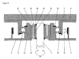
- FIG. 5 shows as a further embodiment that acting in the direction of arrows 42 axial movement of the center column 3 can also be recorded by two cylinder sleeves 37, 38 interconnected via gears.
- the inner cylinder sleeve 38 is rotatably connected with its inner circumference with the outer circumference of the center pillar 3 and has on its outer periphery a longitudinally aligned toothing 39.
- the respective inner ring of the bearing sits on a projection of the rotating part of the drive unit and the outer ring of the bearing on a projection of the fixed part.
- the invention is not limited to this embodiment.
- the invention also claims the kinematic inversion, in which the respective inner ring of the bearing sits on a shoulder of the fixed part and the outer ring of the bearing on a projection of the rotating part of the drive unit.
Landscapes
- Power-Operated Mechanisms For Wings (AREA)
Applications Claiming Priority (1)
| Application Number | Priority Date | Filing Date | Title |
|---|---|---|---|
| DE102015008133.0A DE102015008133A1 (de) | 2015-06-24 | 2015-06-24 | Antriebseinheit für eine automatische Karusselltür |
Publications (3)
| Publication Number | Publication Date |
|---|---|
| EP3109390A1 true EP3109390A1 (fr) | 2016-12-28 |
| EP3109390B1 EP3109390B1 (fr) | 2019-09-04 |
| EP3109390B2 EP3109390B2 (fr) | 2022-06-08 |
Family
ID=55129377
Family Applications (1)
| Application Number | Title | Priority Date | Filing Date |
|---|---|---|---|
| EP15003685.3A Active EP3109390B2 (fr) | 2015-06-24 | 2015-12-29 | Unite d'entrainement pour une porte a tambour automatique |
Country Status (2)
| Country | Link |
|---|---|
| EP (1) | EP3109390B2 (fr) |
| DE (1) | DE102015008133A1 (fr) |
Families Citing this family (1)
| Publication number | Priority date | Publication date | Assignee | Title |
|---|---|---|---|---|
| CN111809999A (zh) * | 2020-08-31 | 2020-10-23 | 裕克施乐塑料制品(太仓)有限公司 | 旋转执行器及具有该旋转执行器的智能门窗 |
Citations (13)
| Publication number | Priority date | Publication date | Assignee | Title |
|---|---|---|---|---|
| DE9319807U1 (de) | 1993-12-23 | 1994-09-15 | Dorma Gmbh & Co Kg | Karusselldrehtür |
| DE4425047A1 (de) | 1994-07-15 | 1996-01-18 | Geze Gmbh & Co | Karusselltür |
| DE19734398B4 (de) | 1997-08-10 | 2007-04-05 | Geze Gmbh | Karusselltür |
| DE102004033304B4 (de) | 2004-07-08 | 2008-04-17 | Dorma Gmbh + Co. Kg | Karusselltür |
| DE102010024108A1 (de) | 2010-06-17 | 2011-12-22 | Dorma Gmbh + Co. Kg | Karuselltür |
| DE102013000423B3 (de) | 2013-01-14 | 2014-03-13 | Dorma Gmbh & Co. Kg | Karusselltür mit einer an einem Glasdeckenelement angeordneten Antriebseinheit |
| EP2755305A2 (fr) * | 2013-01-14 | 2014-07-16 | DORMA GmbH + Co. KG | Unité d'entraînement, notamment pour une porte à tambour, comprenant un moteur multipôles à commutation électronique |
| DE102013000416A1 (de) | 2013-01-14 | 2014-07-17 | Dorma Gmbh & Co. Kg | Verfahren zur Anordnung einer Antriebseinheit in einer Karusselltür |
| DE102013000419A1 (de) | 2013-01-14 | 2014-07-17 | Dorma Gmbh & Co. Kg | Verfahren zur Anordnung einer Antriebseinheit an einem Deckenelement einer Karusselltür |
| DE102013000422A1 (de) | 2013-01-14 | 2014-07-17 | Dorma Gmbh & Co. Kg | Karusselltür mit einer bodenmontierten Antriebseinheit |
| DE102013000420A1 (de) | 2013-01-14 | 2014-07-17 | Dorma Gmbh & Co. Kg | Antriebseinheit für eine Karusselltür mit einer integrierten Blockier- und/oder Bremseinrichtung |
| DE102013000421A1 (de) | 2013-01-14 | 2014-07-17 | Dorma Gmbh & Co. Kg | Antriebseinheit für eine Karusselltür in einer flachen. scheibenförmigen Bauform |
| EP3034761A1 (fr) * | 2014-12-17 | 2016-06-22 | DORMA Deutschland GmbH | Porte à tambour |
Family Cites Families (3)
| Publication number | Priority date | Publication date | Assignee | Title |
|---|---|---|---|---|
| AU2690897A (en) * | 1996-03-20 | 1997-10-10 | Dorma Gmbh & Co. Kg | Revolving door |
| DE102006059947A1 (de) † | 2006-12-19 | 2008-06-26 | Schaeffler Kg | Tandem-Lageranordnung mit einer Vorrichtung zum Ausgleich temperaturbedingter Lagerverspannungen |
| DE102012011048B4 (de) † | 2012-06-02 | 2014-01-02 | Diehl Comfort Modules GmbH | Scharniervorrichtung und eine Türanlage mit der Scharniervorrichtung |
-
2015
- 2015-06-24 DE DE102015008133.0A patent/DE102015008133A1/de not_active Withdrawn
- 2015-12-29 EP EP15003685.3A patent/EP3109390B2/fr active Active
Patent Citations (13)
| Publication number | Priority date | Publication date | Assignee | Title |
|---|---|---|---|---|
| DE9319807U1 (de) | 1993-12-23 | 1994-09-15 | Dorma Gmbh & Co Kg | Karusselldrehtür |
| DE4425047A1 (de) | 1994-07-15 | 1996-01-18 | Geze Gmbh & Co | Karusselltür |
| DE19734398B4 (de) | 1997-08-10 | 2007-04-05 | Geze Gmbh | Karusselltür |
| DE102004033304B4 (de) | 2004-07-08 | 2008-04-17 | Dorma Gmbh + Co. Kg | Karusselltür |
| DE102010024108A1 (de) | 2010-06-17 | 2011-12-22 | Dorma Gmbh + Co. Kg | Karuselltür |
| DE102013000423B3 (de) | 2013-01-14 | 2014-03-13 | Dorma Gmbh & Co. Kg | Karusselltür mit einer an einem Glasdeckenelement angeordneten Antriebseinheit |
| EP2755305A2 (fr) * | 2013-01-14 | 2014-07-16 | DORMA GmbH + Co. KG | Unité d'entraînement, notamment pour une porte à tambour, comprenant un moteur multipôles à commutation électronique |
| DE102013000416A1 (de) | 2013-01-14 | 2014-07-17 | Dorma Gmbh & Co. Kg | Verfahren zur Anordnung einer Antriebseinheit in einer Karusselltür |
| DE102013000419A1 (de) | 2013-01-14 | 2014-07-17 | Dorma Gmbh & Co. Kg | Verfahren zur Anordnung einer Antriebseinheit an einem Deckenelement einer Karusselltür |
| DE102013000422A1 (de) | 2013-01-14 | 2014-07-17 | Dorma Gmbh & Co. Kg | Karusselltür mit einer bodenmontierten Antriebseinheit |
| DE102013000420A1 (de) | 2013-01-14 | 2014-07-17 | Dorma Gmbh & Co. Kg | Antriebseinheit für eine Karusselltür mit einer integrierten Blockier- und/oder Bremseinrichtung |
| DE102013000421A1 (de) | 2013-01-14 | 2014-07-17 | Dorma Gmbh & Co. Kg | Antriebseinheit für eine Karusselltür in einer flachen. scheibenförmigen Bauform |
| EP3034761A1 (fr) * | 2014-12-17 | 2016-06-22 | DORMA Deutschland GmbH | Porte à tambour |
Also Published As
| Publication number | Publication date |
|---|---|
| EP3109390B2 (fr) | 2022-06-08 |
| EP3109390B1 (fr) | 2019-09-04 |
| DE102015008133A1 (de) | 2016-12-29 |
Similar Documents
| Publication | Publication Date | Title |
|---|---|---|
| DE3116775C2 (de) | Lagerungsanordnung einer über ein Gleichlaufdrehgelenk antreibbaren Radnabe | |
| EP3350464B1 (fr) | Engrenage planétaire d'une éolienne avec roues planétaires à paliers lisses | |
| EP2671308B1 (fr) | Logement de rotor pour une machine électrique | |
| WO1983002141A1 (fr) | Dispositif d'entrainement lineaire a deux moteurs | |
| EP1475509B1 (fr) | Dispositif d'entraînement et de blocage | |
| EP2951465B1 (fr) | Engrenage oscillant | |
| DE3245119A1 (de) | Vorrichtung zur umwandlung einer drehenden bewegung in eine lineare bewegung | |
| DE69819826T2 (de) | Servosteuersystem | |
| WO2009024127A2 (fr) | Dispositif de rotation | |
| EP1910707B1 (fr) | Mecanisme de commande pour des instruments, pourvu d'un engrenage planetaire | |
| EP3109390B1 (fr) | Unite d'entrainement pour une porte a tambour automatique | |
| EP0895001A2 (fr) | Réducteur de vitesse | |
| DE102010014393A1 (de) | Tragbares Motorwerkzeug mit einer Unwuchtausgleichsvorrichtung und einer Spannvorrichtung für ein rotationssymmetrisches Arbeitsmittel | |
| DE1552227B2 (de) | Werkzeugmaschine mit einem Arbeitsmotor für Spindel- und Schlittenantrieb und einem Eilgangmotor für den Schlittenantrieb | |
| DE2458399A1 (de) | Universalfraeskopf | |
| DE8115191U1 (de) | "differentialgetriebe" | |
| DE102005016430A1 (de) | Hubvorrichtung | |
| DD263639A5 (de) | Linearantriebseinheit | |
| DE2027993C3 (de) | Antriebsgelenk fur eine Exzenterschneckenpumpe | |
| DE3908586A1 (de) | Cnc-gesteuertes bearbeitungszentrum, insbesondere zum fraesen, bohren und schneiden von massivholz, spanplatten, kunststoff und dgl. | |
| DE102012206667A1 (de) | Axial-Radiallager | |
| DE2925156B1 (de) | Kraftfahrzeug mit Lenkhandrad und einer Antriebseinheit dafuer | |
| DE102018209543A1 (de) | Lenkgetriebe für ein Kraftfahrzeug | |
| EP1696540B1 (fr) | Joint tournant | |
| DE102009024348A1 (de) | Lageranordnung einer über ein Drehgelenk antreibbaren Radnabe eines Kraftfahrzeuges |
Legal Events
| Date | Code | Title | Description |
|---|---|---|---|
| PUAI | Public reference made under article 153(3) epc to a published international application that has entered the european phase |
Free format text: ORIGINAL CODE: 0009012 |
|
| STAA | Information on the status of an ep patent application or granted ep patent |
Free format text: STATUS: THE APPLICATION HAS BEEN PUBLISHED |
|
| AK | Designated contracting states |
Kind code of ref document: A1 Designated state(s): AL AT BE BG CH CY CZ DE DK EE ES FI FR GB GR HR HU IE IS IT LI LT LU LV MC MK MT NL NO PL PT RO RS SE SI SK SM TR |
|
| AX | Request for extension of the european patent |
Extension state: BA ME |
|
| STAA | Information on the status of an ep patent application or granted ep patent |
Free format text: STATUS: REQUEST FOR EXAMINATION WAS MADE |
|
| 17P | Request for examination filed |
Effective date: 20170306 |
|
| RBV | Designated contracting states (corrected) |
Designated state(s): AL AT BE BG CH CY CZ DE DK EE ES FI FR GB GR HR HU IE IS IT LI LT LU LV MC MK MT NL NO PL PT RO RS SE SI SK SM TR |
|
| STAA | Information on the status of an ep patent application or granted ep patent |
Free format text: STATUS: EXAMINATION IS IN PROGRESS |
|
| 17Q | First examination report despatched |
Effective date: 20180103 |
|
| GRAP | Despatch of communication of intention to grant a patent |
Free format text: ORIGINAL CODE: EPIDOSNIGR1 |
|
| STAA | Information on the status of an ep patent application or granted ep patent |
Free format text: STATUS: GRANT OF PATENT IS INTENDED |
|
| INTG | Intention to grant announced |
Effective date: 20190418 |
|
| GRAS | Grant fee paid |
Free format text: ORIGINAL CODE: EPIDOSNIGR3 |
|
| GRAA | (expected) grant |
Free format text: ORIGINAL CODE: 0009210 |
|
| STAA | Information on the status of an ep patent application or granted ep patent |
Free format text: STATUS: THE PATENT HAS BEEN GRANTED |
|
| AK | Designated contracting states |
Kind code of ref document: B1 Designated state(s): AL AT BE BG CH CY CZ DE DK EE ES FI FR GB GR HR HU IE IS IT LI LT LU LV MC MK MT NL NO PL PT RO RS SE SI SK SM TR |
|
| REG | Reference to a national code |
Ref country code: GB Ref legal event code: FG4D Free format text: NOT ENGLISH |
|
| REG | Reference to a national code |
Ref country code: CH Ref legal event code: EP |
|
| REG | Reference to a national code |
Ref country code: AT Ref legal event code: REF Ref document number: 1175574 Country of ref document: AT Kind code of ref document: T Effective date: 20190915 |
|
| REG | Reference to a national code |
Ref country code: DE Ref legal event code: R096 Ref document number: 502015010201 Country of ref document: DE |
|
| REG | Reference to a national code |
Ref country code: IE Ref legal event code: FG4D Free format text: LANGUAGE OF EP DOCUMENT: GERMAN |
|
| RAP2 | Party data changed (patent owner data changed or rights of a patent transferred) |
Owner name: LANDERT GROUP AG |
|
| REG | Reference to a national code |
Ref country code: NL Ref legal event code: MP Effective date: 20190904 |
|
| REG | Reference to a national code |
Ref country code: LT Ref legal event code: MG4D |
|
| PG25 | Lapsed in a contracting state [announced via postgrant information from national office to epo] |
Ref country code: NO Free format text: LAPSE BECAUSE OF FAILURE TO SUBMIT A TRANSLATION OF THE DESCRIPTION OR TO PAY THE FEE WITHIN THE PRESCRIBED TIME-LIMIT Effective date: 20191204 Ref country code: SE Free format text: LAPSE BECAUSE OF FAILURE TO SUBMIT A TRANSLATION OF THE DESCRIPTION OR TO PAY THE FEE WITHIN THE PRESCRIBED TIME-LIMIT Effective date: 20190904 Ref country code: FI Free format text: LAPSE BECAUSE OF FAILURE TO SUBMIT A TRANSLATION OF THE DESCRIPTION OR TO PAY THE FEE WITHIN THE PRESCRIBED TIME-LIMIT Effective date: 20190904 Ref country code: HR Free format text: LAPSE BECAUSE OF FAILURE TO SUBMIT A TRANSLATION OF THE DESCRIPTION OR TO PAY THE FEE WITHIN THE PRESCRIBED TIME-LIMIT Effective date: 20190904 Ref country code: BG Free format text: LAPSE BECAUSE OF FAILURE TO SUBMIT A TRANSLATION OF THE DESCRIPTION OR TO PAY THE FEE WITHIN THE PRESCRIBED TIME-LIMIT Effective date: 20191204 Ref country code: LT Free format text: LAPSE BECAUSE OF FAILURE TO SUBMIT A TRANSLATION OF THE DESCRIPTION OR TO PAY THE FEE WITHIN THE PRESCRIBED TIME-LIMIT Effective date: 20190904 |
|
| PG25 | Lapsed in a contracting state [announced via postgrant information from national office to epo] |
Ref country code: AL Free format text: LAPSE BECAUSE OF FAILURE TO SUBMIT A TRANSLATION OF THE DESCRIPTION OR TO PAY THE FEE WITHIN THE PRESCRIBED TIME-LIMIT Effective date: 20190904 Ref country code: GR Free format text: LAPSE BECAUSE OF FAILURE TO SUBMIT A TRANSLATION OF THE DESCRIPTION OR TO PAY THE FEE WITHIN THE PRESCRIBED TIME-LIMIT Effective date: 20191205 Ref country code: ES Free format text: LAPSE BECAUSE OF FAILURE TO SUBMIT A TRANSLATION OF THE DESCRIPTION OR TO PAY THE FEE WITHIN THE PRESCRIBED TIME-LIMIT Effective date: 20190904 Ref country code: LV Free format text: LAPSE BECAUSE OF FAILURE TO SUBMIT A TRANSLATION OF THE DESCRIPTION OR TO PAY THE FEE WITHIN THE PRESCRIBED TIME-LIMIT Effective date: 20190904 Ref country code: RS Free format text: LAPSE BECAUSE OF FAILURE TO SUBMIT A TRANSLATION OF THE DESCRIPTION OR TO PAY THE FEE WITHIN THE PRESCRIBED TIME-LIMIT Effective date: 20190904 |
|
| PG25 | Lapsed in a contracting state [announced via postgrant information from national office to epo] |
Ref country code: PT Free format text: LAPSE BECAUSE OF FAILURE TO SUBMIT A TRANSLATION OF THE DESCRIPTION OR TO PAY THE FEE WITHIN THE PRESCRIBED TIME-LIMIT Effective date: 20200106 Ref country code: RO Free format text: LAPSE BECAUSE OF FAILURE TO SUBMIT A TRANSLATION OF THE DESCRIPTION OR TO PAY THE FEE WITHIN THE PRESCRIBED TIME-LIMIT Effective date: 20190904 Ref country code: PL Free format text: LAPSE BECAUSE OF FAILURE TO SUBMIT A TRANSLATION OF THE DESCRIPTION OR TO PAY THE FEE WITHIN THE PRESCRIBED TIME-LIMIT Effective date: 20190904 Ref country code: EE Free format text: LAPSE BECAUSE OF FAILURE TO SUBMIT A TRANSLATION OF THE DESCRIPTION OR TO PAY THE FEE WITHIN THE PRESCRIBED TIME-LIMIT Effective date: 20190904 Ref country code: NL Free format text: LAPSE BECAUSE OF FAILURE TO SUBMIT A TRANSLATION OF THE DESCRIPTION OR TO PAY THE FEE WITHIN THE PRESCRIBED TIME-LIMIT Effective date: 20190904 Ref country code: IT Free format text: LAPSE BECAUSE OF FAILURE TO SUBMIT A TRANSLATION OF THE DESCRIPTION OR TO PAY THE FEE WITHIN THE PRESCRIBED TIME-LIMIT Effective date: 20190904 |
|
| PG25 | Lapsed in a contracting state [announced via postgrant information from national office to epo] |
Ref country code: IS Free format text: LAPSE BECAUSE OF FAILURE TO SUBMIT A TRANSLATION OF THE DESCRIPTION OR TO PAY THE FEE WITHIN THE PRESCRIBED TIME-LIMIT Effective date: 20200224 Ref country code: CZ Free format text: LAPSE BECAUSE OF FAILURE TO SUBMIT A TRANSLATION OF THE DESCRIPTION OR TO PAY THE FEE WITHIN THE PRESCRIBED TIME-LIMIT Effective date: 20190904 Ref country code: SM Free format text: LAPSE BECAUSE OF FAILURE TO SUBMIT A TRANSLATION OF THE DESCRIPTION OR TO PAY THE FEE WITHIN THE PRESCRIBED TIME-LIMIT Effective date: 20190904 Ref country code: SK Free format text: LAPSE BECAUSE OF FAILURE TO SUBMIT A TRANSLATION OF THE DESCRIPTION OR TO PAY THE FEE WITHIN THE PRESCRIBED TIME-LIMIT Effective date: 20190904 |
|
| REG | Reference to a national code |
Ref country code: DE Ref legal event code: R026 Ref document number: 502015010201 Country of ref document: DE |
|
| PLBI | Opposition filed |
Free format text: ORIGINAL CODE: 0009260 |
|
| PLAX | Notice of opposition and request to file observation + time limit sent |
Free format text: ORIGINAL CODE: EPIDOSNOBS2 |
|
| 26 | Opposition filed |
Opponent name: DORMAKABA DEUTSCHLAND GMBH Effective date: 20200604 |
|
| PG2D | Information on lapse in contracting state deleted |
Ref country code: IS |
|
| PG25 | Lapsed in a contracting state [announced via postgrant information from national office to epo] |
Ref country code: DK Free format text: LAPSE BECAUSE OF FAILURE TO SUBMIT A TRANSLATION OF THE DESCRIPTION OR TO PAY THE FEE WITHIN THE PRESCRIBED TIME-LIMIT Effective date: 20190904 Ref country code: IS Free format text: LAPSE BECAUSE OF FAILURE TO SUBMIT A TRANSLATION OF THE DESCRIPTION OR TO PAY THE FEE WITHIN THE PRESCRIBED TIME-LIMIT Effective date: 20200105 |
|
| REG | Reference to a national code |
Ref country code: CH Ref legal event code: PL |
|
| REG | Reference to a national code |
Ref country code: BE Ref legal event code: MM Effective date: 20191231 |
|
| PG25 | Lapsed in a contracting state [announced via postgrant information from national office to epo] |
Ref country code: MC Free format text: LAPSE BECAUSE OF FAILURE TO SUBMIT A TRANSLATION OF THE DESCRIPTION OR TO PAY THE FEE WITHIN THE PRESCRIBED TIME-LIMIT Effective date: 20190904 Ref country code: SI Free format text: LAPSE BECAUSE OF FAILURE TO SUBMIT A TRANSLATION OF THE DESCRIPTION OR TO PAY THE FEE WITHIN THE PRESCRIBED TIME-LIMIT Effective date: 20190904 |
|
| GBPC | Gb: european patent ceased through non-payment of renewal fee |
Effective date: 20191229 |
|
| PLBB | Reply of patent proprietor to notice(s) of opposition received |
Free format text: ORIGINAL CODE: EPIDOSNOBS3 |
|
| PG25 | Lapsed in a contracting state [announced via postgrant information from national office to epo] |
Ref country code: LU Free format text: LAPSE BECAUSE OF NON-PAYMENT OF DUE FEES Effective date: 20191229 Ref country code: GB Free format text: LAPSE BECAUSE OF NON-PAYMENT OF DUE FEES Effective date: 20191229 Ref country code: IE Free format text: LAPSE BECAUSE OF NON-PAYMENT OF DUE FEES Effective date: 20191229 Ref country code: FR Free format text: LAPSE BECAUSE OF NON-PAYMENT OF DUE FEES Effective date: 20191231 |
|
| PG25 | Lapsed in a contracting state [announced via postgrant information from national office to epo] |
Ref country code: LI Free format text: LAPSE BECAUSE OF NON-PAYMENT OF DUE FEES Effective date: 20191231 Ref country code: BE Free format text: LAPSE BECAUSE OF NON-PAYMENT OF DUE FEES Effective date: 20191231 Ref country code: CH Free format text: LAPSE BECAUSE OF NON-PAYMENT OF DUE FEES Effective date: 20191231 |
|
| PG25 | Lapsed in a contracting state [announced via postgrant information from national office to epo] |
Ref country code: CY Free format text: LAPSE BECAUSE OF FAILURE TO SUBMIT A TRANSLATION OF THE DESCRIPTION OR TO PAY THE FEE WITHIN THE PRESCRIBED TIME-LIMIT Effective date: 20190904 |
|
| PG25 | Lapsed in a contracting state [announced via postgrant information from national office to epo] |
Ref country code: MT Free format text: LAPSE BECAUSE OF FAILURE TO SUBMIT A TRANSLATION OF THE DESCRIPTION OR TO PAY THE FEE WITHIN THE PRESCRIBED TIME-LIMIT Effective date: 20190904 Ref country code: HU Free format text: LAPSE BECAUSE OF FAILURE TO SUBMIT A TRANSLATION OF THE DESCRIPTION OR TO PAY THE FEE WITHIN THE PRESCRIBED TIME-LIMIT; INVALID AB INITIO Effective date: 20151229 |
|
| REG | Reference to a national code |
Ref country code: AT Ref legal event code: MM01 Ref document number: 1175574 Country of ref document: AT Kind code of ref document: T Effective date: 20201229 |
|
| PG25 | Lapsed in a contracting state [announced via postgrant information from national office to epo] |
Ref country code: AT Free format text: LAPSE BECAUSE OF NON-PAYMENT OF DUE FEES Effective date: 20201229 |
|
| PUAH | Patent maintained in amended form |
Free format text: ORIGINAL CODE: 0009272 |
|
| STAA | Information on the status of an ep patent application or granted ep patent |
Free format text: STATUS: PATENT MAINTAINED AS AMENDED |
|
| PG25 | Lapsed in a contracting state [announced via postgrant information from national office to epo] |
Ref country code: TR Free format text: LAPSE BECAUSE OF FAILURE TO SUBMIT A TRANSLATION OF THE DESCRIPTION OR TO PAY THE FEE WITHIN THE PRESCRIBED TIME-LIMIT Effective date: 20190904 |
|
| 27A | Patent maintained in amended form |
Effective date: 20220608 |
|
| AK | Designated contracting states |
Kind code of ref document: B2 Designated state(s): AL AT BE BG CH CY CZ DE DK EE ES FI FR GB GR HR HU IE IS IT LI LT LU LV MC MK MT NL NO PL PT RO RS SE SI SK SM TR |
|
| REG | Reference to a national code |
Ref country code: DE Ref legal event code: R102 Ref document number: 502015010201 Country of ref document: DE |
|
| PG25 | Lapsed in a contracting state [announced via postgrant information from national office to epo] |
Ref country code: MK Free format text: LAPSE BECAUSE OF FAILURE TO SUBMIT A TRANSLATION OF THE DESCRIPTION OR TO PAY THE FEE WITHIN THE PRESCRIBED TIME-LIMIT Effective date: 20190904 |
|
| PGFP | Annual fee paid to national office [announced via postgrant information from national office to epo] |
Ref country code: DE Payment date: 20231214 Year of fee payment: 9 |