EP3104479B1 - Einbaugehäuse zur einhausung und/oder befestigung von installationen - Google Patents
Einbaugehäuse zur einhausung und/oder befestigung von installationen Download PDFInfo
- Publication number
- EP3104479B1 EP3104479B1 EP16173132.8A EP16173132A EP3104479B1 EP 3104479 B1 EP3104479 B1 EP 3104479B1 EP 16173132 A EP16173132 A EP 16173132A EP 3104479 B1 EP3104479 B1 EP 3104479B1
- Authority
- EP
- European Patent Office
- Prior art keywords
- installation
- insulating material
- frame
- building wall
- housing according
- Prior art date
- Legal status (The legal status is an assumption and is not a legal conclusion. Google has not performed a legal analysis and makes no representation as to the accuracy of the status listed.)
- Active
Links
Images

Classifications
-
- H—ELECTRICITY
- H02—GENERATION; CONVERSION OR DISTRIBUTION OF ELECTRIC POWER
- H02G—INSTALLATION OF ELECTRIC CABLES OR LINES, OR OF COMBINED OPTICAL AND ELECTRIC CABLES OR LINES
- H02G3/00—Installations of electric cables or lines or protective tubing therefor in or on buildings, equivalent structures or vehicles
- H02G3/02—Details
- H02G3/08—Distribution boxes; Connection or junction boxes
- H02G3/12—Distribution boxes; Connection or junction boxes for flush mounting
- H02G3/123—Distribution boxes; Connection or junction boxes for flush mounting in thin walls
-
- H—ELECTRICITY
- H02—GENERATION; CONVERSION OR DISTRIBUTION OF ELECTRIC POWER
- H02G—INSTALLATION OF ELECTRIC CABLES OR LINES, OR OF COMBINED OPTICAL AND ELECTRIC CABLES OR LINES
- H02G3/00—Installations of electric cables or lines or protective tubing therefor in or on buildings, equivalent structures or vehicles
- H02G3/22—Installations of cables or lines through walls, floors or ceilings, e.g. into buildings
-
- E—FIXED CONSTRUCTIONS
- E04—BUILDING
- E04B—GENERAL BUILDING CONSTRUCTIONS; WALLS, e.g. PARTITIONS; ROOFS; FLOORS; CEILINGS; INSULATION OR OTHER PROTECTION OF BUILDINGS
- E04B1/00—Constructions in general; Structures which are not restricted either to walls, e.g. partitions, or floors or ceilings or roofs
- E04B1/62—Insulation or other protection; Elements or use of specified material therefor
- E04B1/74—Heat, sound or noise insulation, absorption, or reflection; Other building methods affording favourable thermal or acoustical conditions, e.g. accumulating of heat within walls
- E04B1/76—Heat, sound or noise insulation, absorption, or reflection; Other building methods affording favourable thermal or acoustical conditions, e.g. accumulating of heat within walls specifically with respect to heat only
- E04B1/762—Exterior insulation of exterior walls
- E04B1/7637—Anchoring of separate elements through the lining to the wall
-
- F—MECHANICAL ENGINEERING; LIGHTING; HEATING; WEAPONS; BLASTING
- F16—ENGINEERING ELEMENTS AND UNITS; GENERAL MEASURES FOR PRODUCING AND MAINTAINING EFFECTIVE FUNCTIONING OF MACHINES OR INSTALLATIONS; THERMAL INSULATION IN GENERAL
- F16C—SHAFTS; FLEXIBLE SHAFTS; ELEMENTS OR CRANKSHAFT MECHANISMS; ROTARY BODIES OTHER THAN GEARING ELEMENTS; BEARINGS
- F16C2300/00—Application independent of particular apparatuses
- F16C2300/10—Application independent of particular apparatuses related to size
- F16C2300/14—Large applications, e.g. bearings having an inner diameter exceeding 500 mm
Definitions
- the invention relates to a mounting housing with the features of the preamble of claim 1.
- Such installation housing are already known and are used for example in the US 4,634,015 , of the DE 20 2004 011259 U1 and the DE 20 2013 000646 U1 shown. Enclosures of this type are attached to building walls and enclose electrical or sanitary installations or installation elements. Furthermore, in the EP 0 710 751 A2 an element for attachment of apparatus and objects to an insulated building facade shown. Both the housing and the element for fixing or enclosing installations or installation elements are fastened to the building wall. An attachment to the building wall (masonry, concrete, ...) is often complicated, since the fastener or the housing must be mounted in a previously created opening in the already attached to the masonry insulation layer on the building wall.
- the object of the invention is to avoid the disadvantages described above and to provide a comparison with the prior art improved installation housing.
- the installation housing according to the invention by the features of the characterizing part of claim 1.
- the cover element can also act as a device carrier and, for example, serve to accommodate electrical or sanitary installations or installation elements. For example. Can be attached to this cover a power outlet, an electrical consumer or a faucet.
- the Built-in housing can serve both as a container for housing components as well as a carrier for attaching components.
- a recess is formed with a border with respect to the opening of the mounting frame, wherein the border is at least partially contacted in the mounting position with the building wall or spaced from the building wall, it is possible to insert the mounting frame directly into an opening in the insulation layer of the building. Due to the generously dimensioned recess with its border, electrical or sanitary installations are framed and edged over a large area. Tolerances on the building wall or protruding irregularities such as mortar or the ribs of bricks are compensated by the spacing of the border to the building wall.
- the mounting frame is formed substantially rectangular, no complicated shapes must be cut out of the insulation material.
- the recess can be cut, for example, with a Styrofoam cutter or a sharp knife from the insulation.
- the mounting frame itself can serve as a template by being held against the wall and its circumference is marked on the facade.
- the recess may be left blank when installing the thermal insulation.
- the mounting frame peripherally at least partially a Mounting portion for attachment to an insulating material is formed.
- the mounting frame forms circumferentially on at least one surface at least one fitting in mounting position of the mounting frame on the outside of the insulating material end web, so that after the adjustment of the mounting frame this can be inserted into the insulation on the building wall up to the stop.
- the at least one end gutter covers any gaps.
- the end bar offers the possibility to attach the frame additionally by means of screws or the like on the insulating material.
- the terminal bar is covered by the cover and remains hidden after installation of the cover.
- the at least one end web on at least one breakthrough through which in mounting position of the mounting housing, a fastening means - in particular mounting foam, foam, insulating foam, Guschaum or insulating foam - is injectable into a cavity between the insulating material and the mounting frame.
- a fastening means - in particular mounting foam, foam, insulating foam, Guschaum or insulating foam - is injectable into a cavity between the insulating material and the mounting frame.
- the cover is attachable as a completely closed cover to the opening of the mounting frame, creates a visually sophisticated surface on the insulated building wall. Furthermore, it is possible to remove the cover to z. B. to get to underlying installation elements, after the insulating body has been removed from the frame. For this reason, a releasable connection between the cover and mounting frame is provided. If the cover has preparations for receiving electrical or sanitary installations, these installations can be easily attached to the cover subsequently. Preparations can z. B. holes and webs or fasteners for lighting elements. If the cover 3 is designed to accommodate electrical or other installations, it proves to be a solid connection with the insulating body 4 is advantageous.
- the mounting frame can be adapted to the installation depth via the predetermined breaking points after determining the layer thickness of the insulation - which essentially results from the thickness of the insulating panels. A complex cutting of the shank of the mounting frame is then not necessary.
- the mounting frame can be adjusted without tools to the installation depth.
- markings can also be made on the mounting frame, which facilitate cutting off by, for example, a saw or a knife to obtain the correct mounting depth.
- the mounting frame is designed telescopically to adapt to an installation depth, then the installation depth can be adjusted without effort or also without tools.
- the insulating body has a handle or a handle ausformt, wherein the handle is disposed at least on the side facing away from the mounting wall in the mounting position of the insulating body.
- the handle is disposed at least on the side facing away from the mounting wall in the mounting position of the insulating body.
- the friction between the insulating body and mounting frame due to a coating can be reduced. A pushing in and pulling out of the mounting frame is thus additionally facilitated and a long life for the insulating body is achieved.
- the insulating body can be designed without sheathing.
- the installation of an installation housing is facilitated and prevents the emergence of a cold bridge. Furthermore, the versatility of the installation housing the opportunity to cover insulation elements on a building wall and at the same time to isolate, or the possibility is created that installation elements to the end element, which is attached to the mounting housing to assemble.
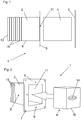
- FIG. 1 The mounting frame 2 forms in the area of the insulation layer of the building wall 31 outwardly opening 11 from a final web 9, which in mounting position flush with the outside of the Insulating material 30 is applied.
- the border 13 In the opposite region of the mounting frame 2 is the border 13, which is introduced in the direction of the building wall 31 in the opening of the insulator 30 existing insulation layer of the building.
- a superior facade consists of facade elements, which are usually plate-shaped and spaced or fixed parallel to the building wall 31 aligned with a building.
- the area behind the superior facade can both remain free - in other words be a cavity between the facade and the building wall 31 - or be filled with an insulating material 30.
- predetermined breaking points 15 via which the mounting frame 2 can be adapted to the strength of the attached to the building wall 31 insulation layer.
- These predetermined breaking points 15 can be designed in different variants. One possibility is to perform the predetermined breaking points so strong that a tool - free separation of the individual segments is possible. Furthermore, it is also possible, the predetermined breaking points 15 to be designed so that, for example. With a sharp knife or saw the mounting frame is easily separable at these locations.
- the insulating body 4 is inserted into the opening 11 of the mounting frame 2. This has substantially the same contour as the inner contour of the mounting frame 2. When the mounting frame 2 has been adapted to the strength of the attached to the building wall 31 insulation layer, and the insulating body 4 must be adjusted. If the insulating body 4 was inserted into the mounting frame 2, this can be covered with the cover 3.
- FIG. 2 shows a mounting housing 1 consisting of mounting frame 2 and an insulating body 4.
- the cover 3 has been omitted for simplicity in this figure.
- the mounting frame 2 forms at its peripheral surfaces a mounting portion 8.
- This attachment portion 8 is subsequently connected to the surrounding insulation material 30 of the building insulation.
- a liquid, foam-like or pasty fastening means 32 are injected.
- the insulating body 4 can be inserted by means of a handle 14 in the mounting frame 2. The extraction from the mounting frame 2 is facilitated by the handle 14.
- the insulating body 4 has a sheath 16. This sheath 16 protects the insulating body 4 against surface damage or facilitates the insertion and withdrawal of the insulating body 4 relative to the mounting frame 2.
- the handle 14 may be attached to the insulating body 4 or be formed by the insulating body 4.
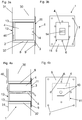
- FIG. 3a schematically shows a mounting housing 1 in a sectional view in the side view.
- the mounting frame 2 was inserted into an opening in the insulating material 30 and encloses an electrical or sanitary installation 40 which is fixed to the building wall 31.
- This can, for example, be formed by a separation point for a lightning rod or by another device, such. B. a water meter or a stopcock.
- the insulating body 4 is inserted into the mounting frame 2.
- the mounting frame 2 terminates at the building wall 31 with the recess 12.
- the border 13 does not contact, or at least in sections, the building wall 31.
- To seal off environmental influences such as rain or due to the visual appearance of a cover 3 is mounted over the opening 11 of the mounting frame 2.
- the attachment of the cover 3 is carried out releasably and can, for example, via a screw or click connection.
- the mounting frame 2 is connected via the mounting portions 8 exclusively with the insulating material 30.
- a connection of the mounting frame 2 with the building wall 31 is not necessary.
- FIG. 3b shows the substantially rectangular shaped housing housing 1 in the front view with inserted Dämmstoff emotions 4.
- the mounting housing 1 could also have the shape of another polygonal or circular shape.
- the insulating body 4 can also be formed by injecting foam-like and hardening foam into the installation housing 1.
- the cover member 3 has been omitted in this view for the sake of simplicity.
- anchor points 7 In the end web 9 are anchor points 7 for an additional attachment of the mounting housing 1 to the insulating material 30. However, this attachment is not mandatory, but can be done for example as a pre-assembly before foaming the mounting frame 2.
- the at least one opening 6 serves for injecting the fastening means 32.
- the handle 14 on the insulating body 4 facilitates the installation and removal of the insulating body 4.
- FIG. 4a shows a variant of the mounting housing as a fastener for installations or objects to be attached to the outside of the insulating material 30.
- the insulating body 4 in this case has a channel 5, which serves to perform an electrical or sanitary installation 40 in the form of a cable or a pipe for sanitary facilities.
- the mounting frame 2 is fastened by means of fastening means 32 on the insulating material 30.
- An attachment to the building wall 31 is not provided.
- the cover 3 can be attached directly to the insulating body 4 or mounting frame 2 is not releasably secured, or even releasably and independently of the insulating body 4 are attached to the mounting frame 2.
- the dimension of the channel 5 is adapted to the dimension of the sanitary or electrical installation 40 in order to reduce or eliminate the effect of the cold bridge.
- the channel 5 may not be executed.
- the channel 5 is to be made as needed during assembly.
- FIG. 4b shows, as well FIG. 3b , the installation housing 1 in the front view without cover 3.
- the anchor points 7 are provided for an additional attachment to the insulation material 30, the anchor points 7 are provided. An attachment via the anchor points 7 is not mandatory.
- the openings 6 are used for injection of a fastener 32.
- the cover 3 is the preparation 10 for attachment of z.
- As an electrical consumer such as a lamp or for sanitary facilities such. B. a faucet.
- Fig. 5a shows a further embodiment of the installation housing 1.
- a recess is provided in the insulating body 4, in which a can 20 can be used.
- This box 20 is used for example for receiving a socket or a switch for an electrical device. However, it can also be z.
- a water meter can be used on a water pipe in this recess.
- This sealant 17 may be performed, for example, by a self-adhesive and elastic sealing tape, a silicone bead or an attachable rubber seal and provides a secure separation between the interior of the mounting frame 2 and located on the outside of the mounting frame 2 insulation material 30 ago.
- the electrical or sanitary installation 40 is guided in the form of a cable or a conduit through the channel 5 through the insulating body 4.
- the channel 5 may not be executed. In this case, the channel should be made as needed during installation.
- Fig. 5b shows the variant from the Fig. 5a in the front view.
- a can 20 can be used in the recess of the insulating body 4.
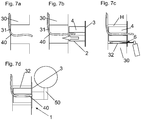
- Fig. 6a shows the first step of the assembly process for installing a built-in housing 1.
- the electrical or sanitary installation 40 exposed by cutting out the adjacent insulation material 30.
- the size of the cutout is defined by the size of the mounting frame 2.
- the cutout is slightly larger than the circumference of the installation housing 1, since the resulting cavity H (see Fig. 6b ) by a fastener 32 (see Fig. 6b ) is completed.
- Fig. 6b shows the adapted, inserted mounting frame 2, which rests with the end webs 9 on the outside of the insulating material 30.
- the mounting frame 2 can now z. B. are connected by screws to the anchor points 7 with the insulating material 30.
- a fastening means 32 is injected into the cavity H via the apertures 6.
- the cavity H is substantially completely filled by the fastening means 32 and thus the emergence of a cold bridge is prevented. Furthermore, a dimensionally stable connection between the mounting frame 2 and insulation 30 is formed.
- Fig. 6c shows the insertion of the insulating body 4 in the mounting frame 2.
- the fastener 32 is already cured at this time and the mounting frame 2 integrated in the insulation material 30.
- Fig. 6d shows how the cover 3 is fixed to the mounting frame 2.
- the attachment shown here is detachable.
- Fig. 7a shows a first assembly step of the variant of the installation housing 1, which is used as a device carrier.
- the area around an electrical or sanitary installation 40 for example in the form of a line, recessed.
- the insulating material 30 can be cut out in this area or released during the laying of the insulating material 30.
- Fig. 7b shows the introduction of the insulating body 4, wherein in this variant, a mounting frame 2 is already attached to the insulating body 4 or is formed by this. Previously, the length of the mounting frame 2 and the insulating body 4 must be adapted to the thickness of the insulating material 30.
- the electrical or sanitary installation 40 is threaded through the channel 5 during insertion of the insulating body 4.
- Fig. 7c shows the next step after insertion of the Dämmstoff emotionss 4.
- the cavity H between insulating body 4 and insulation material 30 is thereby filled by means of fastening means 32.
- the fastening means 32 is injected via the at least one opening 6 in the cavity H.
- Fig. 7d shows the application of the built-in housing 1 as a device carrier.
- a consumer 50 was attached to the cover 3. In this case, it is a lamp. Instead of a lamp z.
Landscapes
- Engineering & Computer Science (AREA)
- Architecture (AREA)
- Civil Engineering (AREA)
- Structural Engineering (AREA)
- Physics & Mathematics (AREA)
- Acoustics & Sound (AREA)
- Electromagnetism (AREA)
- Details Of Indoor Wiring (AREA)
- Building Environments (AREA)
Priority Applications (1)
| Application Number | Priority Date | Filing Date | Title |
|---|---|---|---|
| PL16173132T PL3104479T3 (pl) | 2015-06-09 | 2016-06-06 | Wbudowana obudowa do pomieszczenia i/lub mocowania instalacji |
Applications Claiming Priority (1)
| Application Number | Priority Date | Filing Date | Title |
|---|---|---|---|
| ATA362/2015A AT517268B1 (de) | 2015-06-09 | 2015-06-09 | Einbaugehäuse zur Einhausung und/oder Befestigung von Installationen |
Publications (2)
| Publication Number | Publication Date |
|---|---|
| EP3104479A1 EP3104479A1 (de) | 2016-12-14 |
| EP3104479B1 true EP3104479B1 (de) | 2018-08-29 |
Family
ID=56117537
Family Applications (1)
| Application Number | Title | Priority Date | Filing Date |
|---|---|---|---|
| EP16173132.8A Active EP3104479B1 (de) | 2015-06-09 | 2016-06-06 | Einbaugehäuse zur einhausung und/oder befestigung von installationen |
Country Status (3)
| Country | Link |
|---|---|
| EP (1) | EP3104479B1 (pl) |
| AT (1) | AT517268B1 (pl) |
| PL (1) | PL3104479T3 (pl) |
Families Citing this family (3)
| Publication number | Priority date | Publication date | Assignee | Title |
|---|---|---|---|---|
| DE202018006898U1 (de) * | 2017-11-06 | 2024-03-13 | Atg Profile Holding Aps | Steckdosenelement |
| DE102021106639A1 (de) | 2021-03-18 | 2022-09-22 | Metall- und Plastikwaren Putz Gesellschaft m.b.H. | Installationsdose, insbesondere Elektro-Installationsdose, und deren Montage |
| CA216499S (en) * | 2022-10-20 | 2025-08-05 | 2721111 Ontario Inc | Receptacle within which to mount utilities |
Family Cites Families (8)
| Publication number | Priority date | Publication date | Assignee | Title |
|---|---|---|---|---|
| BE857267A (fr) * | 1977-07-28 | 1978-01-30 | Electrification Et Travaux Spe | Barriere coupe-feu |
| US4419535A (en) * | 1981-07-31 | 1983-12-06 | Hara Robert J O | Multi-cable conduit for floors and walls |
| NL8701274A (nl) * | 1987-05-29 | 1988-12-16 | Pidou Bv | Doorvoerinrichting. |
| GB2216220B (en) * | 1988-03-03 | 1992-11-11 | Mann Mcgowan Fabrications Ltd | Fire damper sleeves |
| DE202004011259U1 (de) * | 2003-11-07 | 2004-09-23 | Wichmann Brandschutzsysteme Gmbh & Co. Kg | Brandschutz-Kabeldurchführung |
| JP2011074969A (ja) * | 2009-09-29 | 2011-04-14 | Inaba Denki Sangyo Co Ltd | 貫通穴閉塞構造及びそれに用いられる貫通穴閉塞キット |
| DE202013000646U1 (de) * | 2013-01-23 | 2013-05-08 | Bernhard Frank | Lasttragende wärmebrückenminimierte Durchdringung von Dämmschichten in der Gebäudehülle |
| CZ26856U1 (cs) * | 2014-03-14 | 2014-04-24 | KOPOS KOLĂŤN a.s. | Elektroinstalační krabice, zejména pro zateplené fasády budov |
-
2015
- 2015-06-09 AT ATA362/2015A patent/AT517268B1/de active
-
2016
- 2016-06-06 PL PL16173132T patent/PL3104479T3/pl unknown
- 2016-06-06 EP EP16173132.8A patent/EP3104479B1/de active Active
Also Published As
| Publication number | Publication date |
|---|---|
| AT517268B1 (de) | 2017-03-15 |
| EP3104479A1 (de) | 2016-12-14 |
| AT517268A1 (de) | 2016-12-15 |
| PL3104479T3 (pl) | 2019-02-28 |
Similar Documents
| Publication | Publication Date | Title |
|---|---|---|
| EP1848082B1 (de) | Elektro-Installationssystem umfassend Gerätedose mit Anlagefläche und gegenüber derletzten versetzter Geräte-Trägerebene | |
| EP2824784B1 (de) | Installationsdose | |
| EP3104479B1 (de) | Einbaugehäuse zur einhausung und/oder befestigung von installationen | |
| EP2096229B1 (de) | Abstandhalter für Dickputzsystem | |
| EP2689808B1 (de) | Baugruppe für eine leitungsdurchführung | |
| EP2610412B1 (de) | Fugenanker für eine Trennfuge zwischen Betonwandelementen | |
| AT507374B1 (de) | Verfahren zur montage bzw. zum einbringen eines hohlkörpers in eine betonwand oder betondecke | |
| CH712235B1 (de) | Installationsdose. | |
| DE102004045136B4 (de) | Verfahren zur Montage eines Auf- oder Unterputzelements an bzw. in einer Wand | |
| EP1422800B1 (de) | Geräteträger zur Befestigung von Geräten auf eine aussen oder innen isolierte Gebäudefassade oder Gebäudemauer | |
| DE102005051596B4 (de) | Aufnahmedose, Befestigungseinrichtung und Verfahren zur Montage einer Aufnahmedose | |
| DE202013001141U1 (de) | Erdungsmontagesystem | |
| DE4416538A1 (de) | Leuchte zum Einbau in eine Wandöffnung | |
| DE3148113A1 (de) | Elektro-installationsdose | |
| DE102013103172A1 (de) | Vorrichtung, Bauanordnung und Verfahren zum Festlegen eines Gerüsts an einer Fassade sowie Verfahren zur Herstellung der Vorrichtung | |
| DE102008028871B4 (de) | Hohlkörper für die Elektroinstallation | |
| DE19815950B4 (de) | Elektrische Hohlwanddose | |
| EP3675297B1 (de) | Halteelement für ein installationsgehäuse | |
| DE2918378A1 (de) | Elektrische anschlussdose | |
| DE10022540A1 (de) | Vorrichtung zum Anbringen von Gegenständen an Gebäudefassaden,-Wänden oder-Decken | |
| DE102010046075A1 (de) | Anordnung zur Befestigung einer Installationsdose für Elektroinstallationen | |
| DE202004020244U1 (de) | Hohlwände mit Kabelkanalsystem | |
| WO2024028047A1 (de) | Modulares baukastensystem zum herstellen und abdichten einer leitungsdurchführung | |
| DE202012102654U1 (de) | Fassadendämmsystem | |
| CH351316A (de) | Bauteilsatz zum Zusammenbau von Installationskasten für elektrische Anlagen |
Legal Events
| Date | Code | Title | Description |
|---|---|---|---|
| PUAI | Public reference made under article 153(3) epc to a published international application that has entered the european phase |
Free format text: ORIGINAL CODE: 0009012 |
|
| STAA | Information on the status of an ep patent application or granted ep patent |
Free format text: STATUS: THE APPLICATION HAS BEEN PUBLISHED |
|
| AK | Designated contracting states |
Kind code of ref document: A1 Designated state(s): AL AT BE BG CH CY CZ DE DK EE ES FI FR GB GR HR HU IE IS IT LI LT LU LV MC MK MT NL NO PL PT RO RS SE SI SK SM TR |
|
| AX | Request for extension of the european patent |
Extension state: BA ME |
|
| STAA | Information on the status of an ep patent application or granted ep patent |
Free format text: STATUS: REQUEST FOR EXAMINATION WAS MADE |
|
| 17P | Request for examination filed |
Effective date: 20170608 |
|
| RBV | Designated contracting states (corrected) |
Designated state(s): AL AT BE BG CH CY CZ DE DK EE ES FI FR GB GR HR HU IE IS IT LI LT LU LV MC MK MT NL NO PL PT RO RS SE SI SK SM TR |
|
| GRAP | Despatch of communication of intention to grant a patent |
Free format text: ORIGINAL CODE: EPIDOSNIGR1 |
|
| STAA | Information on the status of an ep patent application or granted ep patent |
Free format text: STATUS: GRANT OF PATENT IS INTENDED |
|
| RIC1 | Information provided on ipc code assigned before grant |
Ipc: H02G 3/22 20060101AFI20180212BHEP |
|
| INTG | Intention to grant announced |
Effective date: 20180313 |
|
| GRAS | Grant fee paid |
Free format text: ORIGINAL CODE: EPIDOSNIGR3 |
|
| GRAA | (expected) grant |
Free format text: ORIGINAL CODE: 0009210 |
|
| STAA | Information on the status of an ep patent application or granted ep patent |
Free format text: STATUS: THE PATENT HAS BEEN GRANTED |
|
| AK | Designated contracting states |
Kind code of ref document: B1 Designated state(s): AL AT BE BG CH CY CZ DE DK EE ES FI FR GB GR HR HU IE IS IT LI LT LU LV MC MK MT NL NO PL PT RO RS SE SI SK SM TR |
|
| REG | Reference to a national code |
Ref country code: GB Ref legal event code: FG4D Free format text: NOT ENGLISH |
|
| REG | Reference to a national code |
Ref country code: CH Ref legal event code: EP |
|
| REG | Reference to a national code |
Ref country code: AT Ref legal event code: REF Ref document number: 1036280 Country of ref document: AT Kind code of ref document: T Effective date: 20180915 |
|
| REG | Reference to a national code |
Ref country code: IE Ref legal event code: FG4D Free format text: LANGUAGE OF EP DOCUMENT: GERMAN |
|
| REG | Reference to a national code |
Ref country code: DE Ref legal event code: R096 Ref document number: 502016001795 Country of ref document: DE |
|
| REG | Reference to a national code |
Ref country code: CH Ref legal event code: NV Representative=s name: ISLER AND PEDRAZZINI AG, CH |
|
| REG | Reference to a national code |
Ref country code: NL Ref legal event code: MP Effective date: 20180829 |
|
| REG | Reference to a national code |
Ref country code: LT Ref legal event code: MG4D |
|
| PG25 | Lapsed in a contracting state [announced via postgrant information from national office to epo] |
Ref country code: LT Free format text: LAPSE BECAUSE OF FAILURE TO SUBMIT A TRANSLATION OF THE DESCRIPTION OR TO PAY THE FEE WITHIN THE PRESCRIBED TIME-LIMIT Effective date: 20180829 Ref country code: NL Free format text: LAPSE BECAUSE OF FAILURE TO SUBMIT A TRANSLATION OF THE DESCRIPTION OR TO PAY THE FEE WITHIN THE PRESCRIBED TIME-LIMIT Effective date: 20180829 Ref country code: GR Free format text: LAPSE BECAUSE OF FAILURE TO SUBMIT A TRANSLATION OF THE DESCRIPTION OR TO PAY THE FEE WITHIN THE PRESCRIBED TIME-LIMIT Effective date: 20181130 Ref country code: NO Free format text: LAPSE BECAUSE OF FAILURE TO SUBMIT A TRANSLATION OF THE DESCRIPTION OR TO PAY THE FEE WITHIN THE PRESCRIBED TIME-LIMIT Effective date: 20181129 Ref country code: SE Free format text: LAPSE BECAUSE OF FAILURE TO SUBMIT A TRANSLATION OF THE DESCRIPTION OR TO PAY THE FEE WITHIN THE PRESCRIBED TIME-LIMIT Effective date: 20180829 Ref country code: BG Free format text: LAPSE BECAUSE OF FAILURE TO SUBMIT A TRANSLATION OF THE DESCRIPTION OR TO PAY THE FEE WITHIN THE PRESCRIBED TIME-LIMIT Effective date: 20181129 Ref country code: IS Free format text: LAPSE BECAUSE OF FAILURE TO SUBMIT A TRANSLATION OF THE DESCRIPTION OR TO PAY THE FEE WITHIN THE PRESCRIBED TIME-LIMIT Effective date: 20181229 Ref country code: RS Free format text: LAPSE BECAUSE OF FAILURE TO SUBMIT A TRANSLATION OF THE DESCRIPTION OR TO PAY THE FEE WITHIN THE PRESCRIBED TIME-LIMIT Effective date: 20180829 Ref country code: FI Free format text: LAPSE BECAUSE OF FAILURE TO SUBMIT A TRANSLATION OF THE DESCRIPTION OR TO PAY THE FEE WITHIN THE PRESCRIBED TIME-LIMIT Effective date: 20180829 |
|
| PG25 | Lapsed in a contracting state [announced via postgrant information from national office to epo] |
Ref country code: HR Free format text: LAPSE BECAUSE OF FAILURE TO SUBMIT A TRANSLATION OF THE DESCRIPTION OR TO PAY THE FEE WITHIN THE PRESCRIBED TIME-LIMIT Effective date: 20180829 Ref country code: AL Free format text: LAPSE BECAUSE OF FAILURE TO SUBMIT A TRANSLATION OF THE DESCRIPTION OR TO PAY THE FEE WITHIN THE PRESCRIBED TIME-LIMIT Effective date: 20180829 Ref country code: LV Free format text: LAPSE BECAUSE OF FAILURE TO SUBMIT A TRANSLATION OF THE DESCRIPTION OR TO PAY THE FEE WITHIN THE PRESCRIBED TIME-LIMIT Effective date: 20180829 |
|
| PG25 | Lapsed in a contracting state [announced via postgrant information from national office to epo] |
Ref country code: IT Free format text: LAPSE BECAUSE OF FAILURE TO SUBMIT A TRANSLATION OF THE DESCRIPTION OR TO PAY THE FEE WITHIN THE PRESCRIBED TIME-LIMIT Effective date: 20180829 Ref country code: EE Free format text: LAPSE BECAUSE OF FAILURE TO SUBMIT A TRANSLATION OF THE DESCRIPTION OR TO PAY THE FEE WITHIN THE PRESCRIBED TIME-LIMIT Effective date: 20180829 Ref country code: RO Free format text: LAPSE BECAUSE OF FAILURE TO SUBMIT A TRANSLATION OF THE DESCRIPTION OR TO PAY THE FEE WITHIN THE PRESCRIBED TIME-LIMIT Effective date: 20180829 Ref country code: CZ Free format text: LAPSE BECAUSE OF FAILURE TO SUBMIT A TRANSLATION OF THE DESCRIPTION OR TO PAY THE FEE WITHIN THE PRESCRIBED TIME-LIMIT Effective date: 20180829 Ref country code: ES Free format text: LAPSE BECAUSE OF FAILURE TO SUBMIT A TRANSLATION OF THE DESCRIPTION OR TO PAY THE FEE WITHIN THE PRESCRIBED TIME-LIMIT Effective date: 20180829 |
|
| PG25 | Lapsed in a contracting state [announced via postgrant information from national office to epo] |
Ref country code: SK Free format text: LAPSE BECAUSE OF FAILURE TO SUBMIT A TRANSLATION OF THE DESCRIPTION OR TO PAY THE FEE WITHIN THE PRESCRIBED TIME-LIMIT Effective date: 20180829 Ref country code: SM Free format text: LAPSE BECAUSE OF FAILURE TO SUBMIT A TRANSLATION OF THE DESCRIPTION OR TO PAY THE FEE WITHIN THE PRESCRIBED TIME-LIMIT Effective date: 20180829 Ref country code: DK Free format text: LAPSE BECAUSE OF FAILURE TO SUBMIT A TRANSLATION OF THE DESCRIPTION OR TO PAY THE FEE WITHIN THE PRESCRIBED TIME-LIMIT Effective date: 20180829 |
|
| REG | Reference to a national code |
Ref country code: DE Ref legal event code: R097 Ref document number: 502016001795 Country of ref document: DE |
|
| PLBE | No opposition filed within time limit |
Free format text: ORIGINAL CODE: 0009261 |
|
| STAA | Information on the status of an ep patent application or granted ep patent |
Free format text: STATUS: NO OPPOSITION FILED WITHIN TIME LIMIT |
|
| 26N | No opposition filed |
Effective date: 20190531 |
|
| PG25 | Lapsed in a contracting state [announced via postgrant information from national office to epo] |
Ref country code: SI Free format text: LAPSE BECAUSE OF FAILURE TO SUBMIT A TRANSLATION OF THE DESCRIPTION OR TO PAY THE FEE WITHIN THE PRESCRIBED TIME-LIMIT Effective date: 20180829 |
|
| PG25 | Lapsed in a contracting state [announced via postgrant information from national office to epo] |
Ref country code: MC Free format text: LAPSE BECAUSE OF FAILURE TO SUBMIT A TRANSLATION OF THE DESCRIPTION OR TO PAY THE FEE WITHIN THE PRESCRIBED TIME-LIMIT Effective date: 20180829 |
|
| REG | Reference to a national code |
Ref country code: BE Ref legal event code: MM Effective date: 20190630 |
|
| PG25 | Lapsed in a contracting state [announced via postgrant information from national office to epo] |
Ref country code: TR Free format text: LAPSE BECAUSE OF FAILURE TO SUBMIT A TRANSLATION OF THE DESCRIPTION OR TO PAY THE FEE WITHIN THE PRESCRIBED TIME-LIMIT Effective date: 20180829 |
|
| PG25 | Lapsed in a contracting state [announced via postgrant information from national office to epo] |
Ref country code: IE Free format text: LAPSE BECAUSE OF NON-PAYMENT OF DUE FEES Effective date: 20190606 |
|
| PG25 | Lapsed in a contracting state [announced via postgrant information from national office to epo] |
Ref country code: BE Free format text: LAPSE BECAUSE OF NON-PAYMENT OF DUE FEES Effective date: 20190630 Ref country code: LU Free format text: LAPSE BECAUSE OF NON-PAYMENT OF DUE FEES Effective date: 20190606 |
|
| PG25 | Lapsed in a contracting state [announced via postgrant information from national office to epo] |
Ref country code: PT Free format text: LAPSE BECAUSE OF FAILURE TO SUBMIT A TRANSLATION OF THE DESCRIPTION OR TO PAY THE FEE WITHIN THE PRESCRIBED TIME-LIMIT Effective date: 20181229 |
|
| PGFP | Annual fee paid to national office [announced via postgrant information from national office to epo] |
Ref country code: PL Payment date: 20200605 Year of fee payment: 5 |
|
| GBPC | Gb: european patent ceased through non-payment of renewal fee |
Effective date: 20200606 |
|
| PG25 | Lapsed in a contracting state [announced via postgrant information from national office to epo] |
Ref country code: GB Free format text: LAPSE BECAUSE OF NON-PAYMENT OF DUE FEES Effective date: 20200606 |
|
| PG25 | Lapsed in a contracting state [announced via postgrant information from national office to epo] |
Ref country code: CY Free format text: LAPSE BECAUSE OF FAILURE TO SUBMIT A TRANSLATION OF THE DESCRIPTION OR TO PAY THE FEE WITHIN THE PRESCRIBED TIME-LIMIT Effective date: 20180829 |
|
| PG25 | Lapsed in a contracting state [announced via postgrant information from national office to epo] |
Ref country code: HU Free format text: LAPSE BECAUSE OF FAILURE TO SUBMIT A TRANSLATION OF THE DESCRIPTION OR TO PAY THE FEE WITHIN THE PRESCRIBED TIME-LIMIT; INVALID AB INITIO Effective date: 20160606 Ref country code: MT Free format text: LAPSE BECAUSE OF FAILURE TO SUBMIT A TRANSLATION OF THE DESCRIPTION OR TO PAY THE FEE WITHIN THE PRESCRIBED TIME-LIMIT Effective date: 20180829 |
|
| PG25 | Lapsed in a contracting state [announced via postgrant information from national office to epo] |
Ref country code: MK Free format text: LAPSE BECAUSE OF FAILURE TO SUBMIT A TRANSLATION OF THE DESCRIPTION OR TO PAY THE FEE WITHIN THE PRESCRIBED TIME-LIMIT Effective date: 20180829 |
|
| REG | Reference to a national code |
Ref country code: AT Ref legal event code: MM01 Ref document number: 1036280 Country of ref document: AT Kind code of ref document: T Effective date: 20210606 |
|
| PG25 | Lapsed in a contracting state [announced via postgrant information from national office to epo] |
Ref country code: AT Free format text: LAPSE BECAUSE OF NON-PAYMENT OF DUE FEES Effective date: 20210606 |
|
| PG25 | Lapsed in a contracting state [announced via postgrant information from national office to epo] |
Ref country code: PL Free format text: LAPSE BECAUSE OF NON-PAYMENT OF DUE FEES Effective date: 20210606 |
|
| PGFP | Annual fee paid to national office [announced via postgrant information from national office to epo] |
Ref country code: FR Payment date: 20240701 Year of fee payment: 9 |
|
| PGFP | Annual fee paid to national office [announced via postgrant information from national office to epo] |
Ref country code: DE Payment date: 20250704 Year of fee payment: 10 |
|
| PGFP | Annual fee paid to national office [announced via postgrant information from national office to epo] |
Ref country code: CH Payment date: 20250710 Year of fee payment: 10 |