EP3101186B1 - Sanitärwaschvorrichtung - Google Patents
Sanitärwaschvorrichtung Download PDFInfo
- Publication number
- EP3101186B1 EP3101186B1 EP16172922.3A EP16172922A EP3101186B1 EP 3101186 B1 EP3101186 B1 EP 3101186B1 EP 16172922 A EP16172922 A EP 16172922A EP 3101186 B1 EP3101186 B1 EP 3101186B1
- Authority
- EP
- European Patent Office
- Prior art keywords
- water
- tank
- strainer
- disposed
- washing apparatus
- Prior art date
- Legal status (The legal status is an assumption and is not a legal conclusion. Google has not performed a legal analysis and makes no representation as to the accuracy of the status listed.)
- Not-in-force
Links
Images


Classifications
-
- E—FIXED CONSTRUCTIONS
- E03—WATER SUPPLY; SEWERAGE
- E03D—WATER-CLOSETS OR URINALS WITH FLUSHING DEVICES; FLUSHING VALVES THEREFOR
- E03D9/00—Sanitary or other accessories for lavatories ; Devices for cleaning or disinfecting the toilet room or the toilet bowl; Devices for eliminating smells
- E03D9/08—Devices in the bowl producing upwardly-directed sprays; Modifications of the bowl for use with such devices ; Bidets; Combinations of bowls with urinals or bidets; Hot-air or other devices mounted in or on the bowl, urinal or bidet for cleaning or disinfecting
-
- E—FIXED CONSTRUCTIONS
- E03—WATER SUPPLY; SEWERAGE
- E03C—DOMESTIC PLUMBING INSTALLATIONS FOR FRESH WATER OR WASTE WATER; SINKS
- E03C1/00—Domestic plumbing installations for fresh water or waste water; Sinks
- E03C1/02—Plumbing installations for fresh water
- E03C1/10—Devices for preventing contamination of drinking-water pipes, e.g. means for aerating self-closing flushing valves
- E03C1/102—Devices for preventing contamination of drinking-water pipes, e.g. means for aerating self-closing flushing valves using an air gap device
Definitions
- the inventions relates to a sanitary washing apparatus.
- a sanitary washing apparatus has been known that is disposed on top of a western style toilet body and washes a human body with discharged water.
- a backflow prevention mechanism may be attached to the sanitary washing apparatus.
- the backflow prevention mechanism serves to prevent the backflow of sewage through a flow passage, and to thereby prevent the contamination of the water in the piping.
- the backflow prevention mechanism may include an air gap which is a space communicating with the atmosphere and disposed at such a position as to split up the flow passage.
- a standard for the backflow prevention mechanism is clearly defined in each of the European countries, and the product in these countries has to meet the standard.
- tap water is hard water, which is known to produce a precipitate (hereinafter “scale”) such as calcium carbonate when heated.
- a tank with a heating function is disposed at a downstream side of the backflow prevention mechanism so as to heat the water stored therein (see, for example, Japanese Laid-Open Patent Application No. 2010-090621 ).
- Another sanitary washing apparatus representing the closest prior art is described in WO2015/037199 .
- the sanitary washing apparatus includes a nozzle, a water passage, a tank, a backflow prevention mechanism, a pump, a case, and a strainer.
- the nozzle is configured to discharge water toward a private part of a user.
- the water passage is configured to communicate with the nozzle and a water supply pipe.
- the tank is disposed on the water passage.
- the tank is provided with a heating element inside thereof and configured to store water therein.
- the tank is configured to supply water to the nozzle.
- the backflow prevention mechanism is disposed on the water passage and upstream of the tank.
- the backflow prevention mechanism includes an air gap communicating with an atmosphere, thereby preventing backflow of water.
- the pump is disposed downstream of the tank and supplies water stored in the tank to the nozzle.
- the case houses the tank, the nozzle, the pump, and the backflow prevention mechanism.
- the case has an opening.
- the strainer is detachably mounted on the tank such that attachment and/or detachment work of the strainer is conducted through the opening of the case.
- the strainer filters water that flows from the tank to the pump.
- the tank includes a water drain hole that discharges water stored therein.
- the strainer is attached to or detached from the water drain hole. Thereby, a strainer is detached from a water drain hole so that scale in a tank can be discharged reliably.
- the strainer includes a head, a shaft with a diameter less than that of the head, and an engagement part that is disposed on the shaft on a side of the head and engages with the water drain hole.
- the tank includes a flexible cover that has one end communicating with the water drain hole and a cylindrical shape having an aperture at a lower side of a peripheral surface thereof and contacts, from an outside thereof, the head at a position where the head of the strainer in a case where engagement of the engagement part with the water drain hole is released plugs the other end.
- the case preferably includes, on a bottom surface thereof, a water drainage channel that guides, to a bowl of a toilet, water that flows out of the water drain hole. Thereby, water that flows out of a water drain hole can be discharged to a bowl of a toilet.
- the water drain hole is preferably provided in such a manner that at least a portion of an aperture thereof in the tank is disposed under the heating element.
- scale in a tank of a sanitary washing apparatus can readily be discharged.
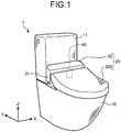
- FIG. 1 is a perspective view that schematically illustrates a toilet apparatus with a sanitary washing apparatus according to an embodiment.
- FIG. 1 illustrate a three-dimensional orthogonal coordinate system where a direction of an X-axis, a direction of a Y-axis, and a direction of a Z-axis that are orthogonal to one another are defined and a positive direction of the Z-axis is a vertically upward direction.
- Such an orthogonal coordinate system may also be illustrated in other drawings to be used for an explanation described below.
- a toilet apparatus 1 includes a western style toilet (that will be described as a "toilet” below) 10 and a sanitary washing apparatus 20, and is installed in a toilet room.
- the toilet 10 is of a low tank type that executes washing with water stored in a water storage tank 11, and is not limited thereto but may be, for example, of a flush valve type.
- the toilet 10 illustrated in Fig. 1 is floor-mounted type. However, the toilet 10 is not limited thereto but may be of a wall-mounted type or the like.
- the sanitary washing apparatus 20 is disposed on top of the toilet 10.
- the sanitary washing apparatus 20 includes a body part 30, a toilet lid 300, and a non-illustrated toilet seat. Both the toilet lid 300 and the toilet seat are mounted on the body part 30 so as to be openable and closable.
- the body part 30 includes a case 31 and a nozzle unit 40.
- the case 31 houses the nozzle unit 40 and the like. A detailed configuration of the case 31 will be described later.
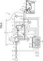
- FIG. 2 is an illustration diagram that illustrates an example of a configuration of the sanitary washing apparatus 20 that includes the nozzle unit 40.
- the nozzle unit 40 includes a discharge nozzle 41 that discharges water toward a private part or the like of a user.
- water does not necessarily mean cold water and may include hot water.
- the discharge nozzle 41 has a discharge hole 42 that is an opening at a tip thereof.
- the discharge nozzle 41 is configured to be movable back and forth with respect to the case 31 (see FIG. 1 ).
- a non-illustrated driving source such as a motor is connected to the discharge nozzle 41.
- the discharge nozzle 41 is moved back and forth between a position where the discharge nozzle 41 has been moved forth into a bowl 12 of the toilet 10 and a position where the discharge nozzle 41 has been moved back into, and is housed, in the case 31.
- the discharge nozzle 41 discharges water toward a body of a user to wash a private part thereof.
- the sanitary washing apparatus 20 further includes a water supply part (or water passage) 50, a control part 200, a seating sensor 210, and an operation part 220.
- the water supply part 50, the control part 200, and the seating sensor 210 as mentioned above are disposed in the body part 30.
- the water supply part 50 supplies water from a water supply pipe A that is a water supply source to the nozzle unit 40.
- the water supply part 50 includes a first flow passage 60, a hot water storage type heat exchanger 70 (that will be described as a "heat exchanger 70" below), and a second flow passage 100.
- the first flow passage 60 is a flow passage from the water supply pipe A to a backflow prevention mechanism 90.
- the backflow prevention mechanism 90 will be described in more detail below.
- the second flow passage 100 is a flow passage from a tank 80 to the discharge nozzle 41 of the nozzle unit 40.
- the heat exchanger 70 includes the tank 80 and stores water supplied from the water supply pipe A through the first flow passage 60. Water stored in the tank 80 is heated to produce hot water and such produced hot water is supplied to the nozzle unit 40 through the second flow passage 100.
- a backflow prevention mechanism needs to be attached to the sanitary washing apparatus 20 in order to prevent sewage from flowing backward on the first flow passage 60 or the like and thereby contaminating the water supply pipe A.
- a backflow prevention mechanism is a mechanism that forms an atmosphere open space that is a space that is open to an atmosphere (air gap) in the middle of a flow passage from the water supply pipe A to the nozzle unit 40 to divide the flow passage.
- an open-type tank is separately disposed on an upstream side of a tank of a heat exchanger and such an open-type tank is provided with a vertical-type backflow prevention mechanism that spouts water in a vertical direction.
- Water stored in such an open-type tank is pumped to such a tank of a heat exchanger by a pump disposed on a downstream side of the open-type tank and subsequently supplied to a nozzle unit.
- the above-mentioned vertical-type backflow prevention mechanism is large in a height direction to secure a space thereof, and hence, there is room for improvement from the viewpoint of downsizing of a sanitary washing apparatus.
- a size of such an apparatus may be increased by a space for installation of such an open-type tank.
- the above-mentioned open-type tank is configured to be constantly in a full water state in order to prevent a pump from idling, and to discard, to a bowl of a toilet, excess water that is higher than a predetermined water level in the open-type tank.
- the sanitary washing apparatus 20 according to the present embodiment is configured in such a manner that it is possible to attain downsizing thereof and water saving.
- water stored in the tank 80 of the sanitary washing apparatus 20 is heated to produce hot water.
- stored water that is, water supplied from the water supply pipe A is, for example, hard water that contains a lot of calcium ions or magnesium ions
- scale is readily produced by heating so that the scale may accumulate in the tank 80.
- flow passage clogging may be caused thereby.
- the sanitary washing apparatus 20 is configured in such a manner that it is possible to readily discharge scale in the tank 80.
- the sanitary washing apparatus 20 it is preferable to take out hot water produced in the tank 80 efficiently. That is, for example, in a case where a backflow prevention mechanism is configured to be disposed in the tank 80, as hot water in the tank 80 is used to wash a user, a water level in the tank 80 is gradually lowered and cold water is supplied from the water supply pipe A.
- the sanitary washing apparatus 20 is configured in such a manner that it is possible to take out heated water from the tank 80 efficiently.
- a configuration of the sanitary washing apparatus 20 will be described in detail.
- a strainer for water supply 61 As illustrated in FIG. 2 , a strainer for water supply 61, an electromagnetic valve 62, and a constant flow valve 63 are disposed on the first flow passage 60 in this order from an upstream side thereof.
- the strainer for water supply 61 eliminates a foreign substance such as a contaminant that is incorporated in water supplied from the water supply pipe A.
- the electromagnetic valve 62 is a normally-closed-type valve that is in a closed state at time of no energization thereof, and opens or closes the first flow passage 60 depending on a control signal from the control part 200.
- the constant flow valve 63 regulates water that flows from the water supply pipe A so as to drain a predetermined flow rate or less thereof.
- the heat exchanger 70 includes the above-mentioned tank 80 and the backflow prevention mechanism 90 disposed on an upstream side of the tank 80.
- the tank 80 and the backflow prevention mechanism 90 are formed integrally, and this will be described later.
- the tank 80 is provided with a heating element 71, a float switch 72, a thermistor 73, and a bimetal 74.
- the heating element 71 is disposed closer to a bottom surface 80b inside the tank 80.
- the heating element 71 is energized depending on a control signal from the control part 200 to generate heat so that water stored in the tank 80 is heated.
- a sheath heater can be used for the heating element 71 that is not limited thereto but may be another kind of a heating device such as, for example, a ceramic heater.
- the float switch 72 is disposed at a predetermined position closer to a top of the tank 80, and in a case where a water level in the tank 80 is elevated to a predetermined level or higher, a non-illustrated float rises to output a predetermined signal. That is, the float switch 72 has a function of detecting a water level of water stored in the tank 80. In the present embodiment, the float switch 72 outputs an ON signal in a case where a water level in the tank 80 is a predetermined level or higher, and the float switch 72 will be described later by using FIG. 14 .
- the thermistor 73 and the bimetal 74 are installed inside the tank 80. Positions of installation of the thermistor 73 and the bimetal 74 will be described later.
- the thermistor 73 detects temperature of water in the tank 80 and outputs a signal that indicates detected temperature.
- the bimetal 74 is interposed in an energization circuit (not-illustrated) for the heating element 71.
- the bimetal 74 opens a contact in an energization circuit in a case where temperature of water in the tank 80 is higher than a predetermined level, so that energization of the heating element 71 is blocked.
- a predetermined temperature can be set arbitrary, and it is preferable to set, for example, a value enabling to detect an excessive temperature rise of water in the tank.
- the bimetal 74 functions as a safety device that prevents water in the tank 80 from being excessively heated by the heating element 71.
- the bimetal 74 may be configured in such a manner that the above-mentioned contact is automatically restored or closed to restart heating by the heating element 71.
- a strainer 110 is interposed between the tank 80 and the second flow passage 100.
- a pump 130 is disposed on the second flow passage 100.
- the strainer 110 filters water that flows from the tank 80 to the pump 130. Specifically, the strainer 110 eliminates a foreign substance such as scale that is contained in water that flows out of the tank 80.
- the strainer 110 is configured to be attachable to and detachable from the tank 80, and this will be described later.
- the pump 130 is disposed on a downstream side of the tank 80 and the strainer 110.
- the pump 130 is driven in response to a control signal from the control part 200 and supplies water stored in the tank 80 to the discharge nozzle 41.
- a vacuum breaker 140 is connected to the second flow passage 100 at a position on a downstream side of the tank 80 and an upstream side of the discharge nozzle 41.
- An atmosphere open channel 141 that is a channel with one end that is open to an atmosphere is connected to the vacuum breaker 140.
- a pipe diameter of the second flow passage 100 is set to be greater than a diameter of the discharge hole 42 of the discharge nozzle 41.
- scale clogging can be prevented by increasing a pipe diameter of a flow passage that leads to the discharge nozzle 41 from the tank 80.
- the seating sensor 210 is disposed at, for example, an appropriate position of the case 31 (see FIG. 1 ) and detects that a user sits on a toilet seat.
- the seating sensor 210 outputs a predetermined signal that indicates seating in a case where the seating is detected.
- a light-projecting-and-receiving-type distance sensor can be used for the seating sensor 210.
- the seating sensor 210 is not limited to the above-mentioned distance sensor and another kind of sensor such as, for example, a load sensor that detects a load of a user that acts on a toilet seat may be used.
- the seating sensor 210 is not necessarily required to be disposed in the case 31 and may be disposed on, for example, a wall surface or the like of a toilet room.
- the seating sensor 210 outputs an ON signal in a case where seating of a user is detected, and the seating sensor 210 will be described later by using FIG. 14 .
- the operation part 220 includes an operation button, an operation knob, or the like, such that a user inputs a start instruction for starting washing of a human body or a stop instruction for stopping such washing, and is disposed at an appropriate position in a toilet room.
- the operation part 220 outputs a signal that indicates a start instruction or the like that is input by a user through the operation button or the like.
- a remote controller can be used for the operation part 220 that is not limited thereto and may be mounted on the body part 30.
- the control part 200 controls the entirety of the sanitary washing apparatus 20, and includes, for example, a non-illustrated arithmetic processing unit such as a Central Processing Unit (CPU) and a non-illustrated storage device such as Random Access Memory (RAM).
- a non-illustrated arithmetic processing unit such as a Central Processing Unit (CPU)
- a non-illustrated storage device such as Random Access Memory (RAM).
- the control part 200 executes a process for controlling the electromagnetic valve 62, the heating element 71, the pump 130, the nozzle unit 40, and the like, based on various input signals, and a content of such a process will be described in detail later.
- a reference symbol in FIG. 2 that has not been described will be described by using another drawing, and the reference symbol is provided in FIG. 2 to correspond to such another drawing.
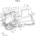
- FIG. 3 is a perspective view of the sanitary washing apparatus 20. Any view in FIG. 3 and subsequent figures that illustrate a configuration of the sanitary washing apparatus 20 is a schematic diagram.
- the case 31 of the sanitary washing apparatus 20 contains various components such as the tank 80 of the heat exchanger 70, the backflow prevention mechanism 90, the discharge nozzle 41, the pump 130, and the control part 200.
- the case 31 includes a case plate 31a and a case cover 31b.
- the case plate 31a (that will be referred to as a "plate 31a” below) includes a plate-shaped bottom surface 31a1 and is mounted on top of the toilet 10 (see FIG. 1 ).
- the plate 31a is formed into a shape with a longitudinal direction along an X-axis and a transverse direction along a Y-axis in a top view.
- Various components such as the tank 80 are disposed on the plate 31a.
- the case cover 31b is configured to be attachable to and detachable from the plate 31a and mounted so as to cover tops of various components disposed on the plate 31a.
- the case cover 31b is indicated by an imaginary line so that an inside of the case 31 is indicated transparently.
- FIG. 3 illustrates a state where the discharge nozzle 41 is housed in a cylindrical housing case 43.
- a term that represents a direction such as a "left side” or a “right side” means a “left side” or a “right side” when the bowl 12 is disposed at a front side in a top view of the sanitary washing apparatus 20 in a state where it is mounted on the toilet 10.
- a negative direction of an X-axis will be referred to as a "left side” and a positive direction of the X-axis will be referred to as a "right side”.
- a negative direction of a Y-axis will be referred to as a "front side” and a positive direction of the Y-axis will be referred to as a "back side”.
- an electronic component such as the control part 200 is disposed on a right side of the discharge nozzle 41.
- an internal space of the case 31 is divided into left and right regions by the discharge nozzle 41 as a boundary, where the water supply part 50 that includes the tank 80 and the like is disposed in one region and an electronic component such as the control part 200 is disposed in the other region.
- a water droplet produced in the water supply part 50 or the like can be prevented from readily scattering toward an electronic component.
- a deodorization unit or the like is also disposed, where illustration thereof is omitted in FIG. 3 .
- Positions of various disposed components illustrated in FIG. 3 or the like are merely illustrations and not limiting.
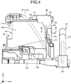
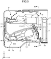
- FIG. 4 is a front view that enlarges and illustrates a neighborhood of the heat exchanger 70 illustrated in FIG. 3
- FIG. 5 is a plan view that enlarges and illustrates a neighborhood of the heat exchanger 70 illustrated in FIG. 3 .
- FIG. 4 and FIG. 5 illustrate a state where the case cover 31b is removed from the plate 31a.
- the backflow prevention mechanism 90 is disposed on top of the tank 80.
- the backflow prevention mechanism 90 is disposed on an upper right portion of the tank 80, in other words, on a side of the discharge nozzle 41 on top of the tank 80.
- the backflow prevention mechanism 90 is disposed on top of the tank 80 and not limited thereto, and the backflow prevention mechanism 90 may be disposed at, for example, an upper position that separates from the tank 80 by a predetermined distance.
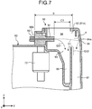
- FIG. 6 is a cross-sectional view of FIG. 5 along a line VI-VI.
- FIG. 6 omits illustration of the plate 31a.
- the backflow prevention mechanism 90 includes a spout port 91, a water-receiving port 92, and a water drain port 93.
- FIG. 7 is a diagram that enlarges and illustrates a neighborhood of the backflow prevention mechanism 90 illustrated in FIG. 6 .
- the spout port 91 is disposed at an end 60a of the first flow passage 60 communicating with the water supply pipe A (see FIG. 2 ).
- the spout port 91 spouts water supplied from the water supply pipe A in a horizontal direction (for example, a positive direction of an X-axis).
- water spouted from the spout port 91 is indicated by an arrow of broken line D1.
- a term of "horizontal”, “vertical”, or the like does not necessarily need mathematically strict precision and a substantial tolerance or error or the like is permitted.
- the water-receiving port 92 is an aperture that is disposed to be opposed to the spout port 91 through an atmosphere open space 94 that is a space that is open to an atmosphere.
- the water-receiving port 92 receives water spouted from the spout port 91. Water received by the water-receiving port 92 flows into the tank 80.
- the water-receiving port 92 is formed in such a manner that an aperture plane thereof is vertical, is not limited thereto, and may be formed, for example, in such a manner that such an aperture plane is inclined.
- the backflow prevention mechanism 90 is a horizontal-type backflow prevention mechanism that spouts water toward the atmosphere open space 94 in a horizontal direction, and has an air gap 94a (see FIG. 6 ) disposed at a site B where a flow passage is divided by the atmosphere open space 94.
- a distance C1 from the spout port 91 to the water-receiving port 92 in the space 94 is set at a value that meets a standard defined in a country or place where the sanitary washing apparatus 20 is installed, and set at, for example, 20 mm or greater.
- the water drain port 93 discharges water remaining in the space 94, for example, outside of the backflow prevention mechanism 90.
- the water drain port 93 is an aperture disposed under the space 94 that is present between the spout port 91 and the water-receiving port 92.
- the water drain port 93 receives and discharges a portion of water spouted from the spout port 91, for example, water with insufficient water force so as not to be received by the water-receiving port 92, in other words, water that does not reach the water-receiving port 92 but remains in the space 94.
- the water drain port 93 discharges water that flows backward from the tank 80, as illustrated by an arrow of dashed-dotted line D22. Water discharged to the water drain port 93 is discharged to the toilet 10 through a water drain channel 85 formed in the tank 80, and this will be described later.
- the sanitary washing apparatus 20 is provided with the above-mentioned backflow prevention mechanism 90, and thereby, for example, a backward flow from the tank 80 to the water supply pipe A can be prevented.
- the backflow prevention mechanism 90 is a horizontal-type backflow prevention mechanism, and hence, the sanitary washing apparatus 20 can be downsized. That is, for example, if the backflow prevention mechanism 90 is a vertical-type backflow prevention mechanism that spouts water in a vertical direction, the above-mentioned distance C1 in the space 94 is secured in a vertical direction. Hence, in a case where a vertical-type backflow prevention mechanism is used, a height of the sanitary washing apparatus 20 may be increased by the distance C1 in the space 94.
- the backflow prevention mechanism 90 in the present embodiment is a horizontal-type backflow prevention mechanism that secures the distance C1 in the space 94 in a horizontal direction, such a height can be reduced, and hence, the sanitary washing apparatus 20 can be downsized even when the backflow prevention mechanism 90 is disposed on top of the tank 80.
- the above-mentioned backflow prevention mechanism 90 is formed integrally with the tank 80, so that the sanitary washing apparatus 20 can be further downsized.
- the tank 80 is formed into a rectangular shape or a substantially rectangular shape that has a space capable of storing water inside thereof, in a cross-sectional side view.
- the tank 80 includes an inflow port 81a, a water inflow pipe 81, an outflow port 82b, a water outflow pipe 82, a water drain hole 83, a direction-changing part 84, and the water drain channel 85.
- the water drain channel 85 may be disposed outside the tank 80.
- the inflow port 81a is the above-mentioned water-receiving port 92 of the backflow prevention mechanism 90. That is, in the present embodiment, the water-receiving port 92 serves as the inflow port 81a of the tank 80. Because the water-receiving port 92 serves as the inflow port 81a of the tank 80, the space 94 (air gap 94a) of the backflow prevention mechanism 90 is also formed on top of the tank 80.
- a part or all of components of the backflow prevention mechanism 90 is/are formed integrally with the tank 80, and thereby, for example, the number of components can be reduced. Thereby, even when the backflow prevention mechanism 90 is disposed on top of the tank 80, a height thereof can be reduced, and as a result, the sanitary washing apparatus 20 can be further downsized.
- the backflow prevention mechanism 90 is formed integrally with the tank 80, and hence, it is also possible to reduce man-hours for installing the backflow prevention mechanism 90 in the tank 80 in a process for producing the sanitary washing apparatus 20.
- the spout port 91 that is installed in the tank 80 is illustrated in FIG. 6 as an example, and is not limited thereto but may be formed integrally with the tank 80.
- the water-receiving port 92 is configured to serve as the inflow port 81a in the above description, and is not limited thereto but may be configured in such a manner that the water-receiving port 92 as a separate body is installed in the inflow port 81a.
- the direction-changing part 84 in the tank 80 is formed at a position to be opposed to the spout port 91 and on an opposite side thereof with respect to the inflow port 81a, in other words, at a position where water passing through the inflow port 81a that serves as the water-receiving port 92 impinges thereon.
- the direction-changing part 84 includes a direction-changing surface 84a that has a predetermined elevation angle ⁇ with respect to an X-axis that is a direction of a spout of water from the spout port 91.
- a predetermined elevation angle ⁇ is set at a value that is, for example, greater than 0 degrees and less than 90 degrees (0° ⁇ ⁇ ⁇ 90°). Therefore, as indicated by the arrow D1, the direction-changing part 84 causes water spouted from the spout port 91 and passing through the water-receiving port 92 (inflow port 81a) to change a direction of its flow downwardly. Thereby, received water can efficiently be guided into the tank 80.
- the water inflow pipe 81 is communicated with the inflow port 81a and formed to extend in a negative direction of a Z-axis.
- An outlet 81b of the water inflow pipe 81 is disposed under the inflow port 81a.
- the outlet 81b of the water inflow pipe 81 is positioned, for example, closer to the bottom surface 80b of the tank 80 and further in a neighborhood of the heating element 71.
- an outlet 181b indicated by an imaginary line is also illustrated, and such an outlet 181b will be described in a variation described below.
- FIG. 8 is a cross-sectional diagram of FIG. 5 along a line VIII - VIII.
- FIG. 8 illustrates a longitudinal cross section of the water inflow pipe 81.
- the water inflow pipe 81 is formed in such a manner that a cross-sectional area of a site close to the outlet 81b (for example, a site indicated by a reference symbol 81 b1) is greater than or equal to a cross-sectional area of a far site 81 a1.
- FIG. 8 illustrates a site around the inflow port 81a as an example of the far site 81 a1.
- the water inflow pipe 81 flows water from the inflow port 81a located upstream to the outlet 81b located downstream and is formed in such a manner that a width of a flow passage is increased in a direction of such a water flow. That is, the water inflow pipe 81 is formed in such a manner that a width W81b1 of a flow passage at the site 81b1 close to the outlet 81b is greater than or equal to a width W81a1 of a flow passage at the far site 81a1.
- FIG. 8 illustrates a value of a flow rate by a length of an arrow D3 or D4. That is, FIG. 8 indicates that a flow rate (arrow D4) of the site 81b1 close to the outlet 81b is less than a flow rate (arrow D3) of the far site 81a1.
- water with a reduced flow rate is guided into the tank 80, so that, for example, floating of scale in the tank 80 can be prevented and water before heating can be held on bottom of the tank 80.
- the outflow port 82b is an aperture that is drilled along a direction of a Z-axis (vertical direction) on bottom of the tank 80 and flows water in the tank 80 to the second flow passage 100 (see FIG. 2 ) through the strainer 110.
- a center line of the outflow port 82b is indicated by a reference symbol 82c.
- the water outflow pipe 82 is communicated with the outflow port 82b and extends in a positive direction of a Z-axis to form an upward inlet 82a.
- the inlet 82a of the water outflow pipe 82 is upward, and hence, for example, scale accumulating on the bottom surface 80b of the case 31 can be prevented from being readily introduced.
- the inlet 82a of the water outflow pipe 82 is disposed at a position higher than the outlet 81b of the water inflow pipe 81 by a predetermined distance C2.
- the inlet 82a of the water outflow pipe 82 is positioned on top of a neighborhood of a side surface on an opposite side of a side surface where the outlet 81b of the water inflow pipe 81 is disposed.
- water passing through the backflow prevention mechanism 90 is guided by the water inflow pipe 81 so as to flow into a bottom of the tank 80, and is heated by the heating element 71.
- heated water is directed upward in the tank 80 by convection thereof, flows to the inlet 82a of the water outflow pipe 82, passes through the water outflow pipe 82, and flows out through the outflow port 82b.
- heated water is directed upward by convection thereof and flows out through the outflow port 82b sequentially, and hence, water before heating does not readily flow out, so that heated water can be taken out from the tank 80 efficiently.
- the predetermined distance C2 is appropriately set based on a volume of the tank 80, a performance of the pump 130, or the like.
- the tank 80 of the heat exchanger 70 is configured as mentioned above, and hence, a configuration that separately provides an open-type tank having a backflow prevention mechanism to discard excess water like a conventional technique is not required, so that water can be saved.
- the bimetal 74 and the thermistor 73 as mentioned above are disposed at positions lower than the inlet 82a of the water outflow pipe 82. Therefore, for example, even when washing of a human body is executed by the discharge nozzle 41 to lower water level of the tank 80, the bimetal 74 and the like are not exposed above water in the tank 80. Thereby, in the present embodiment, the bimetal 74 or the thermistor 73 can reliably be prevented from erroneously detecting air temperature.
- the water drain hole 83 is disposed on a lower side of a side surface of the tank 80 and sealed with the strainer 110. Sealing with the strainer 110 will be described later.
- a position of the water drain hole 83 as illustrated in FIG. 6 is an illustration and not limited thereto.
- the water drain hole 83 is not sealed with the strainer 110, namely, is provided in an open state, so that water stored in the tank 80 is discharged to exterior thereof.
- the water drain hole 83 is provided in such a manner that at least a portion of an aperture in the tank 80 is disposed under the heating element 71. Thereby, in the present embodiment, scale in the tank 80 can be discharged efficiently.
- the water drain hole 83 is disposed in such a manner that a center line 83c is disposed under a center line 71a of the heating element 71.
- the center line 83c of the water drain hole 83 is a line that passes through a center of an aperture plane in the tank 80.
- the center line 71a of the heating element 71 is, for example, a line that passes through a center of a cross section of the heating element 71 in a direction vertical to an axial direction thereof.
- Temperature of the heating element 71 is comparatively high, and hence, scale is readily produced neat the heating element 71.
- the present embodiment is configured as mentioned above, where water in the tank 80 flows so as to go around a periphery of the heating element 71 as indicated by an arrow D6 and is discharged from the water drain hole 83 while scale closer to the heating element 71 is involved therein, so that scale in the tank 80 can be discharged efficiently.
- the water drain channel 85 communicates with the above-mentioned water drain port 93 of the backflow prevention mechanism 90.
- the water drain channel 85 is disposed on an outer wall 80a on a side surface of the tank 80 and formed so as to be exposed partially, as illustrated in FIG. 3 to FIG. 5 and the like.
- the outer wall 80a is a part of a wall of the tank 80 constituting a part of the water drain channel 85.
- FIG. 9 is a cross-sectional view of FIG. 4 along a line IX-IX. Whereas a cover 95 is mounted on a part of the water drain channel 85 in FIG. 4 , FIG. 9 illustrates a state where the cover 95 is removed.
- a partition wall 80c that is formed in the tank 80 is indicated by a broken line in order to distinguish the partition wall 80c from the outer wall 80a of the tank 80.
- the water drain port 93 and the water drain channel 85 are formed into shapes provided by denting the outer wall 80a of the tank 80 toward an inside of the tank 80. Thereby, in the heat exchanger that includes the backflow prevention mechanism 90, the water drain channel 85 is not required to be mounted as a separate member, so that the number of components can be reduced and the tank 80 can be downsized.
- the water inflow pipe 81 is formed in such a manner that the outer wall 80a of the tank 80 is a part of a peripheral surface thereof.
- the outer wall 80a that is a part of a peripheral surface of the water inflow pipe 81 is indicated by a reference symbol 81c provided thereto.
- the water drain channel 85 is disposed adjacent to the water inflow pipe 81 while the outer wall 81c (80a) that is a part of a peripheral surface of the water inflow pipe 81 is interposed therebetween.
- water discharged from the water drain port 93 and flowing on the water drain channel is indicated by an arrow D7.
- the water drain channel 85 is disposed adjacent to and along the water inflow pipe 81 at a comparatively low temperature in the tank 80 of the heat exchanger 70. Hence, water that flows on the water drain channel 85, that is, cold water that does not flow into the tank 80, can be prevented from drawing heat of, and cooling, hot water in the tank 80.
- the water drain port 93 and the water drain channel 85 are disposed at positions in the tank 80 and closer to the discharge nozzle 41. Thereby, a length of the water drain channel 85 of the backflow prevention mechanism 90 can be reduced.
- the case 31 includes a discharge hole 32, a water drainage channel 33, and a taking-out hole (or opening) 34.
- a plurality of the discharge holes 32 are drilled in the bottom surface 31a1 of the plate 31a closer to the central part 31c of the case 31.
- a member that readily produces a water droplet thereon such as the discharge nozzle 41, is disposed around the central part 31c of the case 31, and hence, such a water droplet can readily be discharged from the discharge hole 32.
- the discharge hole 32 is disposed at, for example, a position to face the bowl 12 (see FIG. 2 ) of the toilet 10. Thereby, water that passes through the discharge hole 32 is discharged to the bowl 12.
- the number, positions of disposition, and shapes of the discharge holes 32 illustrated in FIG. 5 and the like are merely illustrations and not limited thereto.
- the water drainage channel 33 is a water drain channel that is used at time of water drainage of the tank 80.
- the water drainage channel 33 is a gutter-shaped wall member that stands on the bottom surface 31a1 of the plate 31a.
- Water drainage of the tank 80 is executed by discharging water from the water drain hole 83 of the tank 80 with the strainer 110 installed therein, as described later. Therefore, the water drainage channel 33 is shaped such that water discharged from the water drain hole 83 is guided to the discharge hole 32, as indicated by an arrow D8.
- the bottom surface 31a1 of the plate 31a with a gradient that is inclined toward the discharge hole 32. Thereby, water on the bottom surface 31a1 can smoothly be discharged toward the discharge hole 32.
- the taking-out hole 34 is an aperture disposed on a side surface of the case 31, and is disposed at a site that corresponds to a position where the strainer 110 is disposed. Therefore, the taking-out hole 34 is a hole for taking out the strainer 110 from the tank 80 as the strainer 110 is removed and cleaned.
- the taking-out hole 34 is an example of an opening.
- the water drain port 93 and the water drain channel 85 are also disposed at positions in the tank 80 and closer to the discharge nozzle 41. Thereby, a length of the water drain channel 85 can be reduced.
- the tank 80 is supplied with water through the water inflow pipe 81 connected to the backflow prevention mechanism 90 that is open to an atmosphere.
- a mechanism is needed that releases air on an upper side in the tank 80 when water is supplied from the water inflow pipe 81 to elevate water level of the tank 80, or introduces air into the tank 80 when water in the tank 80 flows out to lower water level therein.
- an air hole 86 is disposed at an upper side. Air that is introduced into or released from the tank 80 in accordance with a variation of a water level therein passes through the air hole 86. Thereby, air in the tank 80 can be released or air can be introduced into the tank 80.
- An intake or exhaust channel 87 is connected to the air hole 86.
- a tube or the like can be used for the intake or exhaust channel 87 that is not limited thereto.
- the intake or exhaust channel 87 extends to a neighborhood of the discharge hole 32 on the bottom surface 31a1 of the plate 31a, as illustrated in FIG. 3 to FIG. 5 . Thereby, water that is released from the air hole 86 toward exterior of the tank 80 is discharged from the discharge hole 32 through the intake or exhaust channel 87, and hence, water can be prevented from being diffused in the case 31.
- the intake or exhaust channel 87 is configured to serve as the atmosphere open channel 141 of the vacuum breaker 140.
- a position where the intake or exhaust channel 87 and the atmosphere open channel 141 join together is indicated by a reference symbol P.
- the intake or exhaust channel 87 does not only function as an atmosphere open channel that is a channel with one end that is open to an atmosphere, for the air hole 86, but also functions as the atmosphere open channel 141 of the vacuum breaker 140.
- the intake or exhaust channel 87 and the atmosphere open channel 141 can be partially shared with each other, so that the number of components can be reduced and cost can be reduced.
- a downstream side of the outflow port 82b is communicated with the water drain hole 83 and the second flow passage 100 (not illustrated in FIG. 6 ), and the water drain hole 83 is mounted and sealed with the strainer 110 as mentioned above. Therefore, when the water drain hole 83 is sealed with the strainer 110, water in the tank 80 flows from the outflow port 82b to the second flow passage 100 through the strainer 110, as described below.
- the tank 80 includes a cover 120 and the cover 120 is mounted for the water drain hole 83.
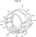
- FIG. 10 is a perspective view of the strainer 110 and FIG. 11 is a perspective view of the cover 120.
- FIG. 12A is a cross-sectional view of FIG. 6 along a line XII - XII.
- the strainer 110 includes a head 111, a shaft 112, and a cap 113.
- the head 111 is formed into a cylindrical shape or a substantially cylindrical shape and includes an operation knob 111a and a flange 111b.
- the operation knob 111a is formed on one end 111c of the head 111.
- the operation knob 111a is a protrusion that is provided to protrude from the end 111c in a direction of separation therefrom, and such a protrusion is held and rotationally-operated by a user or a tool.
- a shape of the operation knob 111a illustrated in FIG. 10 and the like is an illustration, is not limited thereto, and may be, for example, another shape such as a concave shape.
- the flange 111b is formed on the other end 111d of the head 111 and provided to extend in a direction vertical to an axial direction of the head 111 with a cylindrical shape.
- the shaft 112 is formed so as to be continuous with the head 111 and formed into a cylindrical shape or substantially cylindrical shape with a diameter less than that of the head 111.
- the shaft includes a male screw 112a, a flat part 112b, and a filter frame 112c.
- the male screw 112a is disposed on the shaft 112 on a side of the head 111.
- the male screw 112a is partially disposed on the shaft 112 on a side of the head 111. Thereby, for example, a user can execute attachment or detachment of the strainer 110 with respect to the water drain hole 83 as described below, with a comparatively small number of rotational operations.
- the male screw 112a is an example of an engagement part.
- the flat part 112b is a flat site where the male screw 112a is not formed in an axial direction on a side of the head 111 of the shaft 112.
- the flat part 112b is formed at, for example, a position under a nominal diameter of the male screw 112a. A function of the above-mentioned flat part 112b will be described later.
- the filter frame 112c is an aperture disposed around an end 112d of the shaft 112 on an opposite side of the head 111.
- a filter 114 is set in the filter frame 112c.
- the filter 114 is made of a material that does not pass a foreign substance such as scale but pass water.
- a non-woven fabric, a mesh, or the like can be used for the filter 114 that is not limited thereto.
- the numbers or shapes of the filter frame 112c and the filter 114 illustrated in FIG. 10 and the like are illustrations and not limited thereto.
- the cap 113 is formed into a cylindrical shape or substantially cylindrical shape with a diameter less than that of the shaft 112, and includes a sealing part 113a.
- the sealing part 113a is formed into a disc shape or a substantially disc shape, and is disposed on an end 113b of the cap 113.
- a diameter of the sealing part 113a is set at, for example, a value that is slightly less than an aperture diameter of the water drain hole 83 in the tank 80.
- the cap 113 configured as mentioned above is inserted into and engages with a hollow portion of the shaft 112, where a head thereof is an end 113c (see FIG. 12A ) on an opposite side of the end 113b with the sealing part 113a disposed thereon.
- a length of the cap 113 is set at, for example, a value such that the sealing part 113a is exposed from the shaft 112 in a state where the cap 113 is engaged with the shaft 112, and the sealing part 113a is positioned at an aperture of the water drain hole 83 in the tank 80 in a state where the strainer 110 is mounted for the water drain hole 83.
- the strainer 110 with the cap 113 that is a separate member with respect to the head 111 and the shaft 112 is used in the above description, and is not limited thereto, where, for example, the head 111, the shaft 112, and the cap 113 may be integrated.
- the head 111, the shaft 112, and the cap 113 may be separate from one another or any one of them may be separate.
- the strainer 110 further includes a first seal member 116a and a second seal member 116b.
- a first seal member 116a and a second seal member 116b For example, an O-ring can be used for the first or second seal member 116a or 116b that is not limited thereto.
- the first seal member 116a is mounted on the shaft 112 on a side of the head 111.
- the first seal member 116a seals a gap between the shaft 112 and the water drain hole 83 in a watertight manner when the strainer 110 is disposed at a position where the water drain hole 83 is sealed thereby.
- the second seal member 116b is mounted on the sealing part 113a of the cap 113.
- the second seal member 116b seals a gap between the sealing part 113a and the water drain hole 83 in a watertight manner when the strainer 110 is disposed at a position where the water drain hole 83 is sealed thereby.
- the cover 120 includes a peripheral surface 120a, an engagement part 120b, and an opening 120c.
- the cover 120 also includes one end 120d and the other end 120f.
- the peripheral surface 120a is formed into a cylindrical shape or a substantially cylindrical shape.
- a hole for fixation 120e is drilled in the peripheral surface 120a closer to one end 120d.
- a protrusion for fixation 83a with a shape corresponding to the hole for fixation 120e is formed on an outlet side of the water drain hole 83. Therefore, the protrusion for fixation 83a is inserted into the hole for fixation 120e and installed in the water drain hole 83, so that the cover 120 is fixed on an outlet side of the water drain hole 83.
- the engagement part 120b of the cover 120 is disposed in a notch 120g disposed on the peripheral surface 120a on a side of the other end 120f.
- a plurality (for example, two) of the engagement parts 120b are disposed on the peripheral surface 120a at substantially regular intervals.
- a claw 120b1 that protrudes in an inner radial direction is formed at a tip of the engagement part 120b.
- the two engagement parts 120b are disposed on the peripheral surface 120a at positions that are opposed to each other, where the number or positions of disposition of the engagement parts 120b are illustrations and not limited thereto.
- the cover 120 is fabricated by using a material that has flexibility (for example, a resin or the like). Thereby, the cover 120 that includes the engagement part 120b has flexibility, and hence, the engagement part 120b is elastically deformable in a radial direction.
- a material that has flexibility for example, a resin or the like.
- the opening 120c is formed in a rectangular shape in a bottom view and a plurality of (for example, two) openings 120c are formed on a lower side of the peripheral surface 120a in a state where the cover 120 is installed in the water drain hole 83.
- the opening 120c functions as a flow passage for passing water discharged from the tank 80 through the water drain hole 83, and this matter will be described later.
- a shape of the opening 120c is a rectangular shape, is not limited thereto, and may be another shape such as, for example, a circular shape or an elliptical shape.
- the number of the openings 120c is not limited to an example illustrated in FIG. 11 , and may be one or three or more.
- an inner diameter E1 of the peripheral surface 120a of the cover 120 is set to be greater than an outer diameter of the flange 111b of the strainer 110.
- a distance E2 between the claws 120b1 that are oppositely disposed in the cover 120 is set to be less than an outer diameter of the flange 111b.
- An outer diameter of the flange 111b is a site with a maximum diameter in the strainer 110.
- the cover 120 configured as mentioned above is installed in the water drain hole 83 so that one end 120d of the cover 120 is communicated with the water drain hole 83.
- a female screw 83b capable of engaging with the male screw 112a is formed on the water drain hole 83 of the tank 80. Therefore, the male screw 112a is engaged with the female screw 83b, so that the strainer 110 is installed in the water drain hole 83. The male screw 112a is loosened with respect to the female screw 83b, so that the strainer 110 is removed from the water drain hole 83.
- the strainer 110 is provided so as to be attachable to and detachable from the water drain hole 83, and hence, the strainer 110 is removed from the water drain hole 83, so that scale in the tank 80 can reliably be discharged.
- FIG. 12A illustrates a position of the strainer 110 in a case of a normal operation.
- FIG. 12B is a diagram that illustrates a position of the strainer 110 in a case where water drainage for the tank 80 is executed, and
- FIG. 12C is a diagram that illustrates the strainer 110 having been removed in a case where cleaning of the strainer 110 is executed.
- the strainer 110 is engaged with and installed in the water drain hole 83 and positioned so as to seal the water drain hole 83.
- the outflow port 82b of the tank 80 is positioned around the filter 114 of the strainer 110. It is preferable for the outflow port 82b to be positioned in such a manner that the center line 82c is orthogonal to the center line 83c of the water drain hole 83. Thereby, a die for the tank 80 can readily be fabricated, as compared with, for example, a case where the center lines 82c and 83c are not orthogonal to each other, namely, in a case of being skew lines.
- water supplied from the tank 80 passes through the outflow port 82b and the filter 114 as indicated by an arrow D9, and as water passes through the filter 114, scale included therein is captured. Water having passed through the filter 114 flows on the second flow passage 100, and subsequently, is discharged from the discharge nozzle 41 through the pump 130.
- FIG. 12B a case where water drainage for the tank 80 is executed will be described with reference to FIG. 12B .
- the male screw 112a of the strainer 110 is loosened with respect to the female screw 83b.
- a part of the shaft 112 of the strainer 110 moves out of the water drain hole 83 to release engagement with the water drain hole 83 and opens the sealed water drain hole 83.
- water in the tank 80 flows out through a gap between the strainer 110 and the water drain hole 83, as indicated by an arrow D10.
- setting is executed in such a manner that an inner diameter E1 of the peripheral surface 120a of the cover 120 is greater than an outer diameter of the flange 111b of the strainer 110 and a distance E2 between the claws 120b1 is less than an outer diameter of the flange 111b.
- a part of the shaft 112 of the strainer 110 moves out of the water drain hole 83 but the remaining part of the shaft 112 (for example, a site with the filter 114 formed thereon) or the like remains inserted in the water drain hole 83.
- a part of the strainer 110 remains inserted in the water drain hole 83 and is in an idling state, even though engagement with the water drain hole 83 is released.
- the claw 120b1 of the engagement part 120b of the cover 120 contacts, from an outside thereof, the head 111 of the strainer 110 with released engagement of the male screw 112a with the water drain hole 83, at a position where the head 111 seals the other end 120f.
- water that flows out through the water drain hole 83 is held back by the flange 111b, and hence, water that flows out through the tank 80 can be prevented from scattering from a side of the other end 120f as the strainer 110 is removed from the water drain hole 83.
- the strainer 110 is pushed by a water pressure from the water drain hole 83 in a horizontal direction (accurately, a negative direction of an X-axis) to be pressed against and locked on the claws 120b1 of the engagement part 120b, and hence, water that flows out of the tank 80 can be further prevented from scattering.
- a part of the shaft 112 remains in the water drain hole 83, and hence, the strainer 110 does not shake even at time of water drainage.
- the opening 120c is disposed on a lower side of the cover 120, and hence, water that is held back by the flange 111b flows through the opening 120c to exterior thereof.
- the opening 120c functions as a flow passage for flowing water discharged from the tank 80 through the water drain hole 83.
- Water discharged from the opening 120c falls on the plate 31a, is guided to the discharge hole 32 by the above-mentioned water drainage channel 33, and is discharged into the bowl 12 (see an arrow D8 in FIG. 5 ).
- the water drainage channel 33 is disposed on the plate 31a, so that water that flows out of the water drain hole 83 can be discharged into the bowl 12 of the toilet 10.
- the flat part 112b is formed on the shaft 112 of the strainer 110. Thereby, a gap is formed between the female screw 83b of the water drain hole 83 and the flat part 112b. Therefore, as the male screw 112a is loosened to execute water drainage, water starts to flow out through such a gap, and as the male screw 112a is loosened, an amount of water that flows out of the gap is gradually increased.
- the flat part 112b is disposed on the shaft 112 of the strainer 110, so that a flow rate of discharged water can be controlled.
- a diameter of the water drain hole 83 is set to be greater than a diameter of the second flow passage 100 or the outflow port 82b. Thereby, comparatively large scale in the tank 80 can also be readily discharged to exterior thereof. As the above-mentioned water drainage is executed, the pump 130 is not driven, and hence, water in the tank 80 at time of water drainage does not flow to the second flow passage 100.
- water drainage is executed by using the strainer 110 attachable to and detachable from the tank 80, so that scale that accumulates in the tank 80 can readily be discharged to exterior thereof.
- the strainer 110 is removed from the cover 120 in a case where cleaning of the strainer 110 is executed.
- the strainer 110 is pulled in a horizontal direction (accurately, a negative direction of an X-axis) by a user, the claws 120b1 that locks the flange 111b is pushed out in an outer radial direction, and the strainer 110 is pulled out of the cover 120 and removed from the water drain hole 83 and the cover 120.
- the case 31 is provided with the above-mentioned taking-out hole 34 (see FIG. 3 ), and hence, the strainer 110 is taken out through the taking-out hole 34.
- the case 31 is provided with the taking-out hole 34, so that the strainer 110 can be removed from the tank 80 without removing the case cover 31b or the like.
- the engagement part 120b that has been pushed out in an outer radial direction is restored due to elastic deformation thereof, after passing the flange 111b therethrough.
- illustration is omitted, as scale on the filter 114 is removed to complete cleaning of the strainer 110, the strainer 110 is inserted into the cover 120 and the water drain hole 83 while the sealing part 113a of the cap 113 is a leading end thereof.
- the male screw 112a is engaged with the female screw 83b of the water drain hole 83, so that the strainer 110 is installed in and fixed to the water drain hole 83.
- FIG. 13 is a cross-sectional view of FIG. 5 along a line XIII - XIII.
- the case cover 31b of the case 31 includes a rectangular part 36 and a slope part 37.
- the rectangular part 36 is positioned so as to cover a back side of the plate 31a (a positive direction of a Y-axis).
- the rectangular part 36 is provided in such a manner that a front surface 36a and a back surface 36b extend in a vertical direction in an X-axis direction view that is a side view, and a rectangular or substantially rectangular internal space 38 is formed.
- the tank 80 is disposed in the internal space 38.
- the slope part 37 is positioned so as to cover a front side of the plate 31a (a negative direction of a Y-axis).
- the slope part 37 is formed in such a manner that an upper surface 37a thereof is continuous with the rectangular part 36.
- the upper surface 37a of the slope part 37 is continuous with the front surface 36a of the rectangular part 36 on a side of a proximal end 37a1 thereof, and is sloped forward and downward so as to be directed downward on a side of a distal end 37a2 thereof.
- the bowl 12 of the toilet 10 is disposed on a side of the distal end 37a2 as indicated by an imaginary line in FIG. 13 , and hence, the above-mentioned slope part 37 is formed in such a manner that the upper surface 37a is sloped downward on a side of the bowl 12 of the toilet 10 in a side view.
- the slope part 37 configured as mentioned above is provided in such a manner that an internal space 39 with a trapezoidal shape or a substantially trapezoidal shape is formed in a side view.
- the internal space 39 is comparative narrow and has a deformed shape, and hence, is frequently a dead space.
- the above-mentioned pump 130 is contained on a side of the distal end 37a2 of the slope part 37 in the sanitary washing apparatus 20 according to the present embodiment. Thereby, a dead space of the case 31 can be utilized effectively.
- the pump 130 can be positioned under the tank 80.
- the pump 130 may be disposed under the upper surface 37a closer to the bowl 12.
- pipes disposed in the pump 130 are filled with water from the tank 80, and hence, even when the pump 130 is, for example, a non-self-priming pump, it is possible to start discharge of water early after activation thereof.
- the control part 200 includes a state detection unit 201, a water supply control unit 202, and a heating element control unit 203.
- the state detection unit 201, the water supply control unit 202, and the heating element control unit 203 as mentioned above are communicably connected to one another.
- the state detection unit 201 detects a seating state of a user, an operation instruction from a user, or a state of the tank 80.
- the state detection unit 201 detects seating of a user in a case where an ON signal is output from the seating sensor 210, while seat-leaving of a user in a case where an OFF signal is output therefrom.
- the state detection unit 201 detects a start instruction for starting washing of a human body or a stop instruction for stopping such washing that is output from the operation part 220.
- the state detection unit 201 detects that a water level in the tank 80 is a predetermined level or higher in a case where an ON signal is output from the float switch 72. On the other hand, the state detection unit 201 detects that a water level in the tank 80 is lower than a predetermined level in a case where an OFF signal is output from the float switch 72. The state detection unit 201 detects temperature of water in the tank 80 based on a signal that is output from the thermistor 73.
- the water supply control unit 202 controls operations of the electromagnetic valve 62 and the pump 130 based on various states detected by the state detection unit 201. Specifically, the water supply control unit 202 operates the electromagnetic valve 62 to supply water into the tank 80 and drive the pump 130 to discharge water in the tank 80 from the discharge nozzle 41.
- the heating element control unit 203 operates the heating element 71 to heat water in the tank 80 in a case where temperature of water in the tank 80 that is detected by the state detection unit 201 is lower than a reference temperature. On the other hand, the heating element control unit 203 stops an operation of the heating element 71 in a case where temperature of water in the tank 80 is higher than or equal to such a reference temperature.
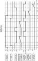
- FIG. 14 is a timing chart that illustrates an example of steps of a process for the sanitary washing apparatus 20 according to the embodiment.
- FIG. 14 illustrates, sequentially from the top, an output signal of the seating sensor 210, a driving state of the pump 130, an output signal of the float switch 72, a cumulative drive time of the pump 130, an open or closed state of the electromagnetic valve 62, an elapsed time after seat-leaving, and a float switch ON time.
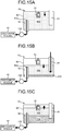
- FIG. 15A to FIG. 15G are illustration diagrams that illustrate a state of water in the tank 80. Hereinafter, timing of supply of water into the tank 80 will be described with a focus and in detail.
- the state detection unit 201 detects an ON signal from the seating sensor 210. Then, as an instruction for starting washing is input by a user through the operation part 220 at a time T2, the water supply control part 202 drives the pump 130 to discharge water (hot water) in the tank 80 from the discharge nozzle 41.
- hot water in the tank 80 is provided with a reference symbol HW and indicated by dots
- cold water is provided with a reference symbol CW and indicated by diagonal lines.
- hot water HW means water heated by the heating element 71 to have temperature around reference temperature
- cold water CW means water at temperature that has not yet reached such reference temperature, for example, immediately after water flows into the tank 80 through the water inflow pipe 81.
- FIG. 14 The description for FIG. 14 is continued, and as an output of the float switch 72 is switched from an ON signal to an OFF signal at a time T3 while water level in the above-mentioned tank 80 is lowered, the water supply control unit 202 activates a timer that measures a cumulative pump drive time.
- the water supply control unit 202 opens the electromagnetic valve 62 to start supply of water into the tank 80.
- cold water CW starts to accumulate around a bottom of the tank 80.
- an amount of water supplied into the tank 80 is greater than an amount of water discharged from the discharge nozzle 41.
- the above-mentioned first predetermined time A1 is set depending on a performance of the pump 130 or the like. Specifically, the first predetermined time A1 is set at, for example, a value such that supply of water is started before a water level in the tank 80 is lowered to expose the inlet 82a of the water outflow pipe 82 above water. Thereby, water discharged from the discharge nozzle 41 can be prevented from being depleted.
- the water supply control unit 202 closes the electromagnetic valve 62 to stop supply of water (see FIG. 15C ).
- a water level in the tank 80 is lowered again, and an output of the float switch 72 is switched from an ON signal to an OFF signal at a time T6.
- the water supply control unit 202 reactivates a timer that measures a cumulative pump drive time.
- the water supply control unit 202 opens the electromagnetic valve 62 to start supply of water into the tank 80, as illustrated in FIG. 15D .
- supply of water is not started at timing when an output of the float switch 72 is switched from an ON signal to an OFF signal, but is started in a case where a cumulative pump drive time is longer than the first predetermined time A1.
- the water supply control unit 202 stops the pump 130 to stop discharge of water from the discharge nozzle 41.
- the water supply control unit 202 also closes the electromagnetic valve 62 to stop supply of water into the tank 80 (see FIG. 15E ).
- the water supply control part 202 measures an elapsed time after seat-leaving at timing when an output of the seating sensor 210 is switched from an ON signal to an OFF signal. Subsequently, as an elapsed time after seat-leaving is longer than a second predetermined time A2 at a time T10, the water supply control unit 202 opens the electromagnetic valve 62 to start supply of water into the tank 80.
- a second predetermined time A2 is settable at an arbitrary value, and for example, is set at a value of a few seconds to several tens of seconds.
- supply of water into the tank 80 is not started immediately after seat-leaving but such supply of water is started after a lapse of the second predetermined time A2.
- hot water HW in the tank 80 can be utilized as effectively as possible.
- a proportion of cold water CW to hot water HW in the tank 80 may be increased to decrease an amount of available hot water HW consequently.
- supply of water is not started in a case of instantaneous seat-leaving, and hence, hot water HW in the tank 80 can be utilized as much as possible.
- the water supply control unit 202 activates a timer that measures a float switch ON time.
- the above-mentioned float switch ON time is a time after seat-leaving and when an output signal of the float switch 72 is an ON signal. That is, as illustrated in FIG. 15F , supply of water into the tank 80 is continued in the present embodiment even when an output of the float switch 72 is an ON signal.
- a float switch ON time is longer than a third predetermined time A3 at a time T12
- the water supply control unit 202 closes the electromagnetic valve 62 to stop supply of water into the tank 80.
- a third predetermined time A3 is settable at an arbitrary value, and is set at, for example, a value of a few seconds to several tens of seconds.
- the outlet 81b of the water inflow pipe 81 is positioned closer to the heating element 71.
- the water inflow pipe 81 is provided in such a manner that the outlet 81b is disposed above the center line 71a of the heating element 71, and is not limited thereto.
- the water inflow pipe 81 is provided in such a manner that an outlet 181b thereof is disposed at a position lower than that of the heating element 71, as indicated by an imaginary line in FIG. 6 .
- the water inflow pipe 81 is provided in such a manner that the outlet 181b is disposed under the center line 71a of the heating element 71.
- the sanitary washing apparatus 20 includes the tank 80, the discharge nozzle 41, the pump 130, the backflow prevention mechanism 90, the case 31, and the strainer 110.
- the tank 80 is provided with the heating element 71 inside thereof and stores water therein.
- the discharge nozzle 41 discharges water in the tank 80 toward a private part of a user.
- the pump 130 is disposed on a downstream side of the tank 80 and supplies water stored in the tank 80 to the discharge nozzle 41.
- the backflow prevention mechanism 90 has the air gap 94a disposed on an upstream side of the tank 80 and at the site B where a flow passage is divided by the atmosphere open space 94.
- the case 31 houses the tank 80, the discharge nozzle 41, the pump 130, and the backflow prevention mechanism 90.
- the strainer 110 is attachable to and detachable from the tank 80 through the taking-out hole 34 of the case 31 and filters water that flows from the tank 80 to the pump 130. Thereby, scale in the tank 80 can readily be discharged.
- the backflow prevention mechanism 90 is a horizontal type, where this is an illustration, is not limited thereto, and may be another kind of backflow prevention mechanism such as a vertical type.
- supply of water into the tank 80 is started after an output of the float switch 72 is switched from an ON signal to an OFF signal and subsequently the first predetermined time A1 is elapsed, and is not limited thereto. That is, for example, supply of water into the tank 80 may be started at a time when an output of the float switch 72 is switched from an ON signal to an OFF signal.
- supply of water into the tank 80 is started after the second predetermined time A2 is elapsed after seat-leaving of a user, and is not limited thereto, and supply of water may be started, for example, immediately after seat-leaving.
- supply of water into the tank 80 is stopped after a user leaves a seat and after a time when an output of the float switch 72 is an ON signal passes through the third predetermined time A3, and is not limited thereto. That is, for example, supply of water into the tank 80 may be stopped at a time when the float switch 72 outputs an ON signal after a user leaves a seat.
Landscapes
- Health & Medical Sciences (AREA)
- Public Health (AREA)
- Life Sciences & Earth Sciences (AREA)
- Engineering & Computer Science (AREA)
- Hydrology & Water Resources (AREA)
- Water Supply & Treatment (AREA)
- Molecular Biology (AREA)
- Epidemiology (AREA)
- Bidet-Like Cleaning Device And Other Flush Toilet Accessories (AREA)
Claims (5)
- Sanitärwaschvorrichtung (20), die umfasst:eine Düse (41), die aufgebaut ist, um Wasser in Richtung eines Intimbereichs eines Benutzers abzugeben;einen Wasserdurchgang (50), der aufgebaut ist, um mit der Düse (41) und einer Wasserversorgungsleitung (A) in Verbindung zu stehen;einen Behälter (80), der auf dem Wasserdurchgang (50) angeordnet ist, wobei der Behälter (80) in seinem Inneren mit einem Heizelement (7) versehen ist und aufgebaut ist, um Wasser darin zu lagern, wobei der Behälter (80) aufgebaut ist, um Wasser an die Düse (41) zu liefern;einen Rückflussverhinderungsmechanismus (90), der auf dem Wasserdurchgang (50) und strömungsaufwärtig von dem Behälter (80) angeordnet ist;eine Pumpe (130), die strömungsabwärtig von dem Behälter (80) angeordnet ist und in dem Behälter (80) gelagertes Wasser an die Düse (41) liefert;ein Gehäuse (31), das den Behälter (80), die Düse (41), die Pumpe (130) und den Rückflussverhinderungsmechanismus (90) aufnimmt, wobei das Gehäuse eine Öffnung (34) hat; undein Filtersieb (110) zum Filtern von Wasser, das von dem Behälter (80) zu der Pumpe fließt;dadurch gekennzeichnet, dassder Rückflussverhinderungsmechanismus (90) einen Luftspalt (94a) umfasst, der mit der Atmosphäre in Verbindung steht, wodurch der Rückfluss von Wasser verhindert wird,und dass das Filtersieb (110) abnehmbar an dem Behälter (80) montiert ist, so dass die Befestigungs- oder Ablösearbeit des Filtersiebs (110) durch die Öffnung (34) des Gehäuses (31) ausgeführt wird.
- Sanitärwaschvorrichtung (20) nach Anspruch 1, wobei:der Behälter (80) ein Loch (83) umfasst, das darin gelagertes Wasser ableitet; unddas Filtersieb (110) abnehmbar an einer Position des Lochs (83) montiert ist.
- Sanitärwaschvorrichtung (20) nach Anspruch 2, wobei
das Filtersieb (110) einen Kopf (111), einen Schaft (112) mit einem kleineren Durchmesser als dem des Kopfs (111) umfasst, wobei der Schaft (112) einen Teil (112a) umfasst, der näher an dem Kopf (111) angeordnet ist und mit dem Loch (83) eingreift, und
der Behälter (80) einen flexiblen Deckel (120) umfasst, der ein Ende (120d) hat, das mit dem Loch (83), dem anderen Ende (120f) und einem Eingreifteil (120b) in Verbindung steht, wobei der flexible Deckel (120) eine zylindrische Form hat, der flexible Deckel (120) eine Öffnung (120c) an einer unteren Position des flexiblen Deckels (120) hat und das Filtersieb (110) in den flexiblen Deckel (120) eingesetzt ist, und das andere Ende (120f) des flexiblen Deckels (120) und der Kopf (111) aneinander angepasst werden, wenn der Kopf (111) den Eingreifteil (120b) des flexiblen Deckels (120) in einem Zustand berührt, in dem der Eingriff des Teils (112a) mit dem Loch (83) gelöst wird. - Sanitärwaschvorrichtung (20) nach Anspruch 2 oder 3, wobei das Gehäuse (31) auf seiner Bodenfläche (31a1) einen Kanal (33) umfasst, der Wasser, das aus dem Loch (83) fließt, zu einer Schüssel (12) einer Toilette (10) leitet.
- Sanitärwaschvorrichtung (20) nach Anspruch 2, 3 oder 4, wobei das Loch (83) unter dem Heizungselement (71) angeordnet ist.
Applications Claiming Priority (1)
| Application Number | Priority Date | Filing Date | Title |
|---|---|---|---|
| JP2015115181A JP6596943B2 (ja) | 2015-06-05 | 2015-06-05 | 衛生洗浄装置 |
Publications (2)
| Publication Number | Publication Date |
|---|---|
| EP3101186A1 EP3101186A1 (de) | 2016-12-07 |
| EP3101186B1 true EP3101186B1 (de) | 2018-01-17 |
Family
ID=56101346
Family Applications (1)
| Application Number | Title | Priority Date | Filing Date |
|---|---|---|---|
| EP16172922.3A Not-in-force EP3101186B1 (de) | 2015-06-05 | 2016-06-03 | Sanitärwaschvorrichtung |
Country Status (2)
| Country | Link |
|---|---|
| EP (1) | EP3101186B1 (de) |
| JP (1) | JP6596943B2 (de) |
Families Citing this family (8)
| Publication number | Priority date | Publication date | Assignee | Title |
|---|---|---|---|---|
| JP6369609B1 (ja) * | 2017-07-25 | 2018-08-08 | Toto株式会社 | 衛生洗浄装置 |
| JP6909434B2 (ja) * | 2017-07-25 | 2021-07-28 | Toto株式会社 | 衛生洗浄装置 |
| JP6891698B2 (ja) * | 2017-07-25 | 2021-06-18 | Toto株式会社 | 衛生洗浄装置 |
| JP6891697B2 (ja) * | 2017-07-25 | 2021-06-18 | Toto株式会社 | 衛生洗浄装置 |
| JP7055277B2 (ja) * | 2018-01-31 | 2022-04-18 | Toto株式会社 | 衛生洗浄装置 |
| EP3768903A4 (de) * | 2018-03-21 | 2022-05-04 | Eczacibasi Yapi Gerecleri Sanayi Ve Ticaret Anonim Sirketi | Montagesystem für bidet-mechanismus |
| US20210017751A1 (en) * | 2018-03-30 | 2021-01-21 | Lixil Corporation | Toilet seat device, toilet device, and descaling agent supply device |
| JP7041392B2 (ja) * | 2018-05-18 | 2022-03-24 | Toto株式会社 | 衛生洗浄装置 |
Family Cites Families (10)
| Publication number | Priority date | Publication date | Assignee | Title |
|---|---|---|---|---|
| DE2826059C3 (de) * | 1977-06-17 | 1981-06-25 | Aisin Seiki K.K., Kariya, Aichi | Duschvorrichtung |
| JP3199361B2 (ja) * | 1997-10-31 | 2001-08-20 | 小糸工業株式会社 | 衛生洗浄装置 |
| JP2004150122A (ja) * | 2002-10-30 | 2004-05-27 | Aisin Seiki Co Ltd | 温水洗浄便座装置 |
| JP2005226253A (ja) * | 2004-02-10 | 2005-08-25 | Inax Corp | 温水洗浄装置 |
| JP5340641B2 (ja) * | 2008-05-26 | 2013-11-13 | 株式会社Lixil | 局部洗浄装置 |
| JP2010090621A (ja) | 2008-10-08 | 2010-04-22 | Toto Ltd | 衛生洗浄装置 |
| JP2012207497A (ja) * | 2011-03-30 | 2012-10-25 | Toto Ltd | 温水タンク |
| DE202012002585U1 (de) * | 2012-03-13 | 2013-06-17 | Neoperl Gmbh | Rückfluss-Sperre für eine Unterdusche |
| JP5919466B2 (ja) * | 2012-05-11 | 2016-05-18 | パナソニックIpマネジメント株式会社 | 衛生洗浄装置 |
| WO2015037199A1 (ja) * | 2013-09-10 | 2015-03-19 | パナソニックIpマネジメント株式会社 | 衛生洗浄装置 |
-
2015
- 2015-06-05 JP JP2015115181A patent/JP6596943B2/ja not_active Expired - Fee Related
-
2016
- 2016-06-03 EP EP16172922.3A patent/EP3101186B1/de not_active Not-in-force
Non-Patent Citations (1)
| Title |
|---|
| None * |
Also Published As
| Publication number | Publication date |
|---|---|
| JP6596943B2 (ja) | 2019-10-30 |
| EP3101186A1 (de) | 2016-12-07 |
| JP2017002501A (ja) | 2017-01-05 |
Similar Documents
| Publication | Publication Date | Title |
|---|---|---|
| EP3101186B1 (de) | Sanitärwaschvorrichtung | |
| EP3101185B1 (de) | Sanitärwaschvorrichtung | |
| JP2010024780A (ja) | トイレ装置 | |
| EP3680404B1 (de) | Sanitärwaschvorrichtung | |
| JP2008106595A (ja) | 水洗大便器 | |
| JP5305213B2 (ja) | 水洗大便器 | |
| JP6714804B2 (ja) | 衛生洗浄装置 | |
| JP2019199789A (ja) | 衛生洗浄装置 | |
| JP6865923B2 (ja) | 水洗大便器 | |
| JP2017002700A (ja) | 衛生洗浄装置 | |
| JP5018259B2 (ja) | 浴室ユニット | |
| JP5130678B2 (ja) | 水洗大便器 | |
| JP2010189935A (ja) | 衛生洗浄装置 | |
| JP6176586B2 (ja) | 即湯システム | |
| JP2006283400A (ja) | 衛生洗浄便座装置及びトイレ装置 | |
| JP7255160B2 (ja) | 浴槽洗浄装置 | |
| EP3434837B1 (de) | Sanitärreinigungsvorrichtung | |
| JP2010090621A (ja) | 衛生洗浄装置 | |
| CN115726440A (zh) | 冲厕装置 | |
| JP2008082031A (ja) | 水洗大便器 | |
| JP2008163604A (ja) | 水洗大便器 | |
| JP6891697B2 (ja) | 衛生洗浄装置 | |
| JP2008057245A (ja) | 水洗大便器 | |
| JP5244036B2 (ja) | 浴槽用循環具 | |
| CN111074984B (zh) | 卫生间用除臭装置以及卫生洗净装置 |
Legal Events
| Date | Code | Title | Description |
|---|---|---|---|
| PUAI | Public reference made under article 153(3) epc to a published international application that has entered the european phase |
Free format text: ORIGINAL CODE: 0009012 |
|
| STAA | Information on the status of an ep patent application or granted ep patent |
Free format text: STATUS: REQUEST FOR EXAMINATION WAS MADE |
|
| 17P | Request for examination filed |
Effective date: 20160603 |
|
| AK | Designated contracting states |
Kind code of ref document: A1 Designated state(s): AL AT BE BG CH CY CZ DE DK EE ES FI FR GB GR HR HU IE IS IT LI LT LU LV MC MK MT NL NO PL PT RO RS SE SI SK SM TR |
|
| AX | Request for extension of the european patent |
Extension state: BA ME |
|
| RBV | Designated contracting states (corrected) |
Designated state(s): AL AT BE BG CH CY CZ DE DK EE ES FI FR GB GR HR HU IE IS IT LI LT LU LV MC MK MT NL NO PL PT RO RS SE SI SK SM TR |
|
| GRAP | Despatch of communication of intention to grant a patent |
Free format text: ORIGINAL CODE: EPIDOSNIGR1 |
|
| STAA | Information on the status of an ep patent application or granted ep patent |
Free format text: STATUS: GRANT OF PATENT IS INTENDED |
|
| INTG | Intention to grant announced |
Effective date: 20170809 |
|
| GRAS | Grant fee paid |
Free format text: ORIGINAL CODE: EPIDOSNIGR3 |
|
| GRAA | (expected) grant |
Free format text: ORIGINAL CODE: 0009210 |
|
| STAA | Information on the status of an ep patent application or granted ep patent |
Free format text: STATUS: THE PATENT HAS BEEN GRANTED |
|
| RAP1 | Party data changed (applicant data changed or rights of an application transferred) |
Owner name: TOTO LTD. |
|
| AK | Designated contracting states |
Kind code of ref document: B1 Designated state(s): AL AT BE BG CH CY CZ DE DK EE ES FI FR GB GR HR HU IE IS IT LI LT LU LV MC MK MT NL NO PL PT RO RS SE SI SK SM TR |
|
| REG | Reference to a national code |
Ref country code: GB Ref legal event code: FG4D |
|
| REG | Reference to a national code |
Ref country code: CH Ref legal event code: EP |
|
| REG | Reference to a national code |
Ref country code: IE Ref legal event code: FG4D |
|
| REG | Reference to a national code |
Ref country code: AT Ref legal event code: REF Ref document number: 964527 Country of ref document: AT Kind code of ref document: T Effective date: 20180215 |
|
| REG | Reference to a national code |
Ref country code: DE Ref legal event code: R096 Ref document number: 602016001364 Country of ref document: DE |
|
| REG | Reference to a national code |
Ref country code: NL Ref legal event code: MP Effective date: 20180117 |
|
| REG | Reference to a national code |
Ref country code: LT Ref legal event code: MG4D |
|
| REG | Reference to a national code |
Ref country code: AT Ref legal event code: MK05 Ref document number: 964527 Country of ref document: AT Kind code of ref document: T Effective date: 20180117 |
|
| PG25 | Lapsed in a contracting state [announced via postgrant information from national office to epo] |
Ref country code: NL Free format text: LAPSE BECAUSE OF FAILURE TO SUBMIT A TRANSLATION OF THE DESCRIPTION OR TO PAY THE FEE WITHIN THE PRESCRIBED TIME-LIMIT Effective date: 20180117 |
|
| PG25 | Lapsed in a contracting state [announced via postgrant information from national office to epo] |
Ref country code: NO Free format text: LAPSE BECAUSE OF FAILURE TO SUBMIT A TRANSLATION OF THE DESCRIPTION OR TO PAY THE FEE WITHIN THE PRESCRIBED TIME-LIMIT Effective date: 20180417 Ref country code: FI Free format text: LAPSE BECAUSE OF FAILURE TO SUBMIT A TRANSLATION OF THE DESCRIPTION OR TO PAY THE FEE WITHIN THE PRESCRIBED TIME-LIMIT Effective date: 20180117 Ref country code: CY Free format text: LAPSE BECAUSE OF FAILURE TO SUBMIT A TRANSLATION OF THE DESCRIPTION OR TO PAY THE FEE WITHIN THE PRESCRIBED TIME-LIMIT Effective date: 20180117 Ref country code: ES Free format text: LAPSE BECAUSE OF FAILURE TO SUBMIT A TRANSLATION OF THE DESCRIPTION OR TO PAY THE FEE WITHIN THE PRESCRIBED TIME-LIMIT Effective date: 20180117 Ref country code: LT Free format text: LAPSE BECAUSE OF FAILURE TO SUBMIT A TRANSLATION OF THE DESCRIPTION OR TO PAY THE FEE WITHIN THE PRESCRIBED TIME-LIMIT Effective date: 20180117 Ref country code: HR Free format text: LAPSE BECAUSE OF FAILURE TO SUBMIT A TRANSLATION OF THE DESCRIPTION OR TO PAY THE FEE WITHIN THE PRESCRIBED TIME-LIMIT Effective date: 20180117 |
|
| PG25 | Lapsed in a contracting state [announced via postgrant information from national office to epo] |
Ref country code: SE Free format text: LAPSE BECAUSE OF FAILURE TO SUBMIT A TRANSLATION OF THE DESCRIPTION OR TO PAY THE FEE WITHIN THE PRESCRIBED TIME-LIMIT Effective date: 20180117 Ref country code: BG Free format text: LAPSE BECAUSE OF FAILURE TO SUBMIT A TRANSLATION OF THE DESCRIPTION OR TO PAY THE FEE WITHIN THE PRESCRIBED TIME-LIMIT Effective date: 20180417 Ref country code: RS Free format text: LAPSE BECAUSE OF FAILURE TO SUBMIT A TRANSLATION OF THE DESCRIPTION OR TO PAY THE FEE WITHIN THE PRESCRIBED TIME-LIMIT Effective date: 20180117 Ref country code: AT Free format text: LAPSE BECAUSE OF FAILURE TO SUBMIT A TRANSLATION OF THE DESCRIPTION OR TO PAY THE FEE WITHIN THE PRESCRIBED TIME-LIMIT Effective date: 20180117 Ref country code: IS Free format text: LAPSE BECAUSE OF FAILURE TO SUBMIT A TRANSLATION OF THE DESCRIPTION OR TO PAY THE FEE WITHIN THE PRESCRIBED TIME-LIMIT Effective date: 20180517 Ref country code: LV Free format text: LAPSE BECAUSE OF FAILURE TO SUBMIT A TRANSLATION OF THE DESCRIPTION OR TO PAY THE FEE WITHIN THE PRESCRIBED TIME-LIMIT Effective date: 20180117 Ref country code: GR Free format text: LAPSE BECAUSE OF FAILURE TO SUBMIT A TRANSLATION OF THE DESCRIPTION OR TO PAY THE FEE WITHIN THE PRESCRIBED TIME-LIMIT Effective date: 20180418 Ref country code: PL Free format text: LAPSE BECAUSE OF FAILURE TO SUBMIT A TRANSLATION OF THE DESCRIPTION OR TO PAY THE FEE WITHIN THE PRESCRIBED TIME-LIMIT Effective date: 20180117 |
|
| REG | Reference to a national code |
Ref country code: DE Ref legal event code: R097 Ref document number: 602016001364 Country of ref document: DE |
|
| PG25 | Lapsed in a contracting state [announced via postgrant information from national office to epo] |
Ref country code: EE Free format text: LAPSE BECAUSE OF FAILURE TO SUBMIT A TRANSLATION OF THE DESCRIPTION OR TO PAY THE FEE WITHIN THE PRESCRIBED TIME-LIMIT Effective date: 20180117 Ref country code: RO Free format text: LAPSE BECAUSE OF FAILURE TO SUBMIT A TRANSLATION OF THE DESCRIPTION OR TO PAY THE FEE WITHIN THE PRESCRIBED TIME-LIMIT Effective date: 20180117 Ref country code: IT Free format text: LAPSE BECAUSE OF FAILURE TO SUBMIT A TRANSLATION OF THE DESCRIPTION OR TO PAY THE FEE WITHIN THE PRESCRIBED TIME-LIMIT Effective date: 20180117 Ref country code: AL Free format text: LAPSE BECAUSE OF FAILURE TO SUBMIT A TRANSLATION OF THE DESCRIPTION OR TO PAY THE FEE WITHIN THE PRESCRIBED TIME-LIMIT Effective date: 20180117 |
|
| PLBE | No opposition filed within time limit |
Free format text: ORIGINAL CODE: 0009261 |
|
| STAA | Information on the status of an ep patent application or granted ep patent |
Free format text: STATUS: NO OPPOSITION FILED WITHIN TIME LIMIT |
|
| PG25 | Lapsed in a contracting state [announced via postgrant information from national office to epo] |
Ref country code: SK Free format text: LAPSE BECAUSE OF FAILURE TO SUBMIT A TRANSLATION OF THE DESCRIPTION OR TO PAY THE FEE WITHIN THE PRESCRIBED TIME-LIMIT Effective date: 20180117 Ref country code: DK Free format text: LAPSE BECAUSE OF FAILURE TO SUBMIT A TRANSLATION OF THE DESCRIPTION OR TO PAY THE FEE WITHIN THE PRESCRIBED TIME-LIMIT Effective date: 20180117 Ref country code: SM Free format text: LAPSE BECAUSE OF FAILURE TO SUBMIT A TRANSLATION OF THE DESCRIPTION OR TO PAY THE FEE WITHIN THE PRESCRIBED TIME-LIMIT Effective date: 20180117 Ref country code: CZ Free format text: LAPSE BECAUSE OF FAILURE TO SUBMIT A TRANSLATION OF THE DESCRIPTION OR TO PAY THE FEE WITHIN THE PRESCRIBED TIME-LIMIT Effective date: 20180117 |
|
| 26N | No opposition filed |
Effective date: 20181018 |
|
| PG25 | Lapsed in a contracting state [announced via postgrant information from national office to epo] |
Ref country code: SI Free format text: LAPSE BECAUSE OF FAILURE TO SUBMIT A TRANSLATION OF THE DESCRIPTION OR TO PAY THE FEE WITHIN THE PRESCRIBED TIME-LIMIT Effective date: 20180117 |
|
| REG | Reference to a national code |
Ref country code: BE Ref legal event code: MM Effective date: 20180630 |
|
| REG | Reference to a national code |
Ref country code: IE Ref legal event code: MM4A |
|
| PG25 | Lapsed in a contracting state [announced via postgrant information from national office to epo] |
Ref country code: LU Free format text: LAPSE BECAUSE OF NON-PAYMENT OF DUE FEES Effective date: 20180603 Ref country code: MC Free format text: LAPSE BECAUSE OF FAILURE TO SUBMIT A TRANSLATION OF THE DESCRIPTION OR TO PAY THE FEE WITHIN THE PRESCRIBED TIME-LIMIT Effective date: 20180117 |
|
| PG25 | Lapsed in a contracting state [announced via postgrant information from national office to epo] |
Ref country code: IE Free format text: LAPSE BECAUSE OF NON-PAYMENT OF DUE FEES Effective date: 20180603 Ref country code: FR Free format text: LAPSE BECAUSE OF NON-PAYMENT OF DUE FEES Effective date: 20180630 |
|
| PG25 | Lapsed in a contracting state [announced via postgrant information from national office to epo] |
Ref country code: BE Free format text: LAPSE BECAUSE OF NON-PAYMENT OF DUE FEES Effective date: 20180630 |
|
| PG25 | Lapsed in a contracting state [announced via postgrant information from national office to epo] |
Ref country code: MT Free format text: LAPSE BECAUSE OF NON-PAYMENT OF DUE FEES Effective date: 20180603 |
|
| REG | Reference to a national code |
Ref country code: CH Ref legal event code: PL |
|
| PG25 | Lapsed in a contracting state [announced via postgrant information from national office to epo] |
Ref country code: TR Free format text: LAPSE BECAUSE OF FAILURE TO SUBMIT A TRANSLATION OF THE DESCRIPTION OR TO PAY THE FEE WITHIN THE PRESCRIBED TIME-LIMIT Effective date: 20180117 |
|
| PG25 | Lapsed in a contracting state [announced via postgrant information from national office to epo] |
Ref country code: PT Free format text: LAPSE BECAUSE OF FAILURE TO SUBMIT A TRANSLATION OF THE DESCRIPTION OR TO PAY THE FEE WITHIN THE PRESCRIBED TIME-LIMIT Effective date: 20180117 Ref country code: LI Free format text: LAPSE BECAUSE OF NON-PAYMENT OF DUE FEES Effective date: 20190630 Ref country code: CH Free format text: LAPSE BECAUSE OF NON-PAYMENT OF DUE FEES Effective date: 20190630 |
|
| PG25 | Lapsed in a contracting state [announced via postgrant information from national office to epo] |
Ref country code: HU Free format text: LAPSE BECAUSE OF FAILURE TO SUBMIT A TRANSLATION OF THE DESCRIPTION OR TO PAY THE FEE WITHIN THE PRESCRIBED TIME-LIMIT; INVALID AB INITIO Effective date: 20160603 Ref country code: MK Free format text: LAPSE BECAUSE OF NON-PAYMENT OF DUE FEES Effective date: 20180117 |
|
| GBPC | Gb: european patent ceased through non-payment of renewal fee |
Effective date: 20200603 |
|
| PG25 | Lapsed in a contracting state [announced via postgrant information from national office to epo] |
Ref country code: GB Free format text: LAPSE BECAUSE OF NON-PAYMENT OF DUE FEES Effective date: 20200603 |
|
| PGFP | Annual fee paid to national office [announced via postgrant information from national office to epo] |
Ref country code: DE Payment date: 20240617 Year of fee payment: 9 |
|
| P01 | Opt-out of the competence of the unified patent court (upc) registered |
Free format text: CASE NUMBER: APP_63054/2024 Effective date: 20241127 |
|
| REG | Reference to a national code |
Ref country code: DE Ref legal event code: R119 Ref document number: 602016001364 Country of ref document: DE |
|
| PG25 | Lapsed in a contracting state [announced via postgrant information from national office to epo] |
Ref country code: DE Free format text: LAPSE BECAUSE OF NON-PAYMENT OF DUE FEES Effective date: 20260101 |