EP3099622B1 - Lift crane with improved movable counterweight - Google Patents
Lift crane with improved movable counterweight Download PDFInfo
- Publication number
- EP3099622B1 EP3099622B1 EP15739792.8A EP15739792A EP3099622B1 EP 3099622 B1 EP3099622 B1 EP 3099622B1 EP 15739792 A EP15739792 A EP 15739792A EP 3099622 B1 EP3099622 B1 EP 3099622B1
- Authority
- EP
- European Patent Office
- Prior art keywords
- counterweight
- crane
- support beam
- rotating bed
- counterweight support
- Prior art date
- Legal status (The legal status is an assumption and is not a legal conclusion. Google has not performed a legal analysis and makes no representation as to the accuracy of the status listed.)
- Active
Links
Images


















Classifications
-
- B—PERFORMING OPERATIONS; TRANSPORTING
- B66—HOISTING; LIFTING; HAULING
- B66C—CRANES; LOAD-ENGAGING ELEMENTS OR DEVICES FOR CRANES, CAPSTANS, WINCHES, OR TACKLES
- B66C23/00—Cranes comprising essentially a beam, boom, or triangular structure acting as a cantilever and mounted for translatory of swinging movements in vertical or horizontal planes or a combination of such movements, e.g. jib-cranes, derricks, tower cranes
- B66C23/62—Constructional features or details
- B66C23/72—Counterweights or supports for balancing lifting couples
- B66C23/74—Counterweights or supports for balancing lifting couples separate from jib
- B66C23/76—Counterweights or supports for balancing lifting couples separate from jib and movable to take account of variations of load or of variations of length of jib
-
- B—PERFORMING OPERATIONS; TRANSPORTING
- B66—HOISTING; LIFTING; HAULING
- B66C—CRANES; LOAD-ENGAGING ELEMENTS OR DEVICES FOR CRANES, CAPSTANS, WINCHES, OR TACKLES
- B66C2700/00—Cranes
- B66C2700/03—Cranes with arms or jibs; Multiple cranes
- B66C2700/0321—Travelling cranes
- B66C2700/0357—Cranes on road or off-road vehicles, on trailers or towed vehicles; Cranes on wheels or crane-trucks
- B66C2700/0364—Cranes on road or off-road vehicles, on trailers or towed vehicles; Cranes on wheels or crane-trucks with a slewing arm
- B66C2700/0371—Cranes on road or off-road vehicles, on trailers or towed vehicles; Cranes on wheels or crane-trucks with a slewing arm on a turntable
Definitions
- the present application relates to lift cranes, and particularly to mobile lift cranes having a counterweight that can be moved to different positions in an effort to balance the combined boom and load moment on the crane.
- Lift cranes typically include counterweights to help balance the crane when the crane lowers its boom and/or lifts a load.
- the counterweight on the rear of the crane is so large that the carbody is also equipped with counterweight to prevent backward tipping when no load is being lifted.
- an extra counterweight attachment such as a counterweight trailer, is sometimes added to the crane to further enhance the lift capacities of the mobile lift crane. Since the load is often moved in and out with respect to the center of rotation of the crane, and thus generates different moments throughout a crane pick, move and set operation, it is advantageous if the counterweight, including any extra counterweight attachments, can also be moved forward and backward with respect to the center of rotation of the crane. In this way a smaller amount of counterweight can be utilized than would be necessary if the counterweight had to be kept at a fixed distance.
- a typical example of the forgoing is a Terex Demag CC8800 crane with a Superlift attachment.
- This crane includes 100 metric tonne of carbody counterweight, 280 metric tonne of upperworks counterweight, and 640 metric tonne on an extra counterweight attachment, for a total of 1020 metric tonne of counterweight.
- the extra counterweight can be moved in and out by a telescoping member. While all of this counterweight makes it possible to lift heavy loads, the counterweight has to be transported whenever the crane is dismantled for moving to a new job site. With U.S. highway constraints, it takes 15 trucks to transport 300 metric tonne of counterweight.
- any extra counterweight attachments also need to be mobile.
- the extra counterweight attachment also has to be able to travel over the ground. This means that the ground has to be prepared and cleared, and often timbers put in place, for swing or travel of the extra counterweight unit.
- U.S. Patent No. 7,546,928 discloses several embodiments of mobile lift cranes with a variable position counterweight that have high capacities with lower amounts of counterweight, and the movable counterweight does not need to be supported by the ground. While these embodiments are great improvements in the high-capacity crane design, there are cranes with lower capacities for which it would also be desirable to increase the capacity of the crane without increasing the total counterweight of the crane, especially if the counterweight did not need to be supported by the ground during crane operation. Further, the cranes in the '928 patent include a fixed position lattice mast structure from which the counterweight is suspended by a tension member.
- a mobile lift crane and method of operation has been invented for smaller capacity cranes that use a reduced amount of total counterweight compared to other cranes of the same capacity, but wherein the crane is still mobile and can lift loads comparable to a crane using significantly more total counterweight.
- a non-claimed example describes a lift crane comprising: a carbody; movable ground engaging members mounted on the carbody allowing the crane to move over the ground; a rotating bed rotatably connected to the carbody about an axis of rotation, the rotating bed comprising a counterweight support frame; a boom pivotally mounted about a fixed boom hinge point on the front portion of the rotating bed and including a load hoist line for handling a load; a boom hoist system connected to the rotating bed and the boom that allows the angle of the boom relative to the plane of rotation of the rotating bed to be changed; a counterweight unit supported on the counterweight support frame in a movable relationship with respect to the counterweight support frame; and a counterweight unit movement device connected between the rotating bed and the counterweight unit so as to
- a non-claimed example describes a lift crane comprising: a carbody; ground engaging members elevating the carbody off the ground; a rotating bed rotatably connected to the carbody about an axis of rotation, the rotating bed having a rear-most fixed portion; a boom pivotally mounted on the front portion of the rotating bed and including a load hoist line for handling a load; a mast connected to the rotating bed, and adjustable-length boom hoist rigging connected between the mast and the boom that allows the angle of the boom relative to the plane of rotation of the rotating bed to be changed; a counterweight support beam moveably connected to the rotating bed; a counterweight support beam movement device connected between the counterweight support beam and the rotating bed such that the counterweight support beam can be moved with respect to the length of the rotating bed away from the rotational connection of the rotating bed and the carbody, and extend rearwardly of the rear-most fixed portion of the rotating bed; a tension member connected between the mast and the counterweight support beam; a counterweight unit supported on the counterweight support beam in a mov
- a non-claimed example describes a mobile lift crane comprising, when set up, a carbody having movable ground engaging members; a rotating bed rotatably connected to the carbody such that the rotating bed can swing about an axis of rotation with respect to the ground engaging members; and a boom pivotally mounted on a front portion of the rotating bed, with a hoist line extending there from; wherein the crane is configured to be set up with two different counterweight set-up configuration options: i) a first counterweight set-up configuration option wherein a first counterweight movement system can move a first counterweight unit between a first position and a second position, wherein the first position is a position in which the first counterweight unit is as near as possible to the axis of rotation for the first counterweight set-up configuration option, constituting a first distance from the axis of rotation, and where the second position is a position in which the first counterweight unit is as far as possible from the axis of rotation for the first counterweight set-up configuration option, constituting a second distance from
- a non-claimed example describes a lift crane comprising: a carbody; ground engaging members elevating the carbody off the ground; a rotating bed rotatably connected to the carbody; a counterweight support beam telescopically connected to the rotating bed such that the rear portion of the counterweight support beam can be extended away from the rotational connection of the rotating bed and the carbody; a boom pivotally mounted on the front portion of the rotating bed and including a load hoist line for handling a load; a mast connected to the rotating bed, and adjustable-length boom hoist rigging connected between the mast and the boom that allows the angle of the boom relative to the plane of rotation of the rotating bed to be changed; a tension member connected between the mast and the counterweight support beam; a counterweight unit supported on the counterweight support beam in a movable relationship with respect to the counterweight support beam; and a counterweight movement system capable of moving the counterweight unit toward the boom to a position in front of the top of the mast and away from the boom to a position rearward of the top of the mast,
- a non-claimed example describes a lift crane comprising: a carbody having movable ground engaging members mounted on the carbody allowing the crane to move over the ground; a rotating bed rotatably connected about an axis of rotation to the carbody such that the rotating bed can swing with respect to the movable ground engaging members; a boom pivotally mounted on the front portion of the rotating bed and including a load hoist line for handling a load; a mast pivotally mounted on the rotating bed at a first end; a boom hoist system comprising pendants connected between the mast and the boom, the boom and mast being connected together with a fixed length of rigging between the boom and the mast, and a boom hoist system mounted between the mast and the rotating bed, the boom hoist system allowing the angle of the boom relative to the plane of rotation of the rotating bed to be changed; a movable counterweight unit supported on the rotating bed; and a counterweight movement system connected between the rotating bed and the counterweight unit so as to be able to move the counterweight unit toward and away from the boom.
- a non-claimed example describes mobile lift crane comprising: a carbody having movable ground engaging members; a rotating bed rotatably connected about an axis of rotation to the carbody such that the rotating bed can swing with respect to the movable ground engaging members; a boom pivotally mounted on a front portion of the rotating bed; an upperworks counterweight unit that rotates with the rotating bed and is never supported by the ground during crane pick, move and set operations other than indirectly by the movable ground engaging members on the carbody, wherein the ratio of i) the weight of the upperworks counterweight unit to ii) the total weight of the crane equipped with a basic boom length is greater than 52%.
- a lift crane includes a rotating bed having a front portion and a rear-most fixed portion. Movable ground engaging members mounted on a carbody of the crane and allow the crane to move over the ground.
- the rotating bed is rotatably connected to the carbody about an axis of rotation that provides a plane of rotation perpendicular to the axis.
- the rotating bed includes a counterweight support frame with a rack coupled directly to a lower surface of the rotating bed, the rack having teeth formed therein.
- a boom is pivotally mounted about a fixed boom hinge point on the front portion of the rotating bed and includes a load hoist line for handling a load.
- a boom hoist system is connected to the rotating bed and the boom and allows the angle of the boom relative to the plane of rotation of the rotating bed to be changed.
- the lift crane also includes a counterweight unit with a trolley.
- the counterweight unit is supported on the counterweight support frame in a movable relationship with respect to the counterweight support frame.
- a counterweight unit movement device is connected between the counterweight support frame and the counterweight unit so as to be able to move the counterweight unit toward and away from the boom.
- the counterweight unit movement device includes at least one motor driving a gear connected to the trolley. The gear engages the teeth on the rack to move the trolley with respect to the counterweight support frame as the motor turns the gear.
- a lift crane comprising a rotating bed having a front portion and a rear-most fixed portion.
- Movable ground engaging members mount on a carbody and allow the crane to move over the ground.
- the rotating bed is rotatably connected to the carbody about an axis of rotation that provides a plane of rotation perpendicular to the axis.
- the rotating bed includes a counterweight support frame with a rack coupled directly to a lower surface of the rotating bed, the rack having teeth formed therein.
- a boom is pivotally mounted about a fixed boom hinge point on the front portion of the rotating bed and includes a load hoist line for handling a load.
- a boom hoist system is connected to the rotating bed and the boom and allows the angle of the boom relative to the plane of rotation of the rotating bed to be changed.
- the lift crane also includes a counterweight unit with a trolley.
- the counterweight unit is in a movable relationship with respect to the rotating bed.
- a counterweight unit movement device is configured to move the counterweight unit toward and away from the boom.
- the counterweight unit movement device includes at least one motor driving a gear connected to the trolley to move the trolley with respect to the rotating body as the motor turns the gear.
- a yet another non-claimed example describes a lift crane comprising a rotating bed having a front portion and a rear-most fixed portion. Movable ground engaging members mount on a carbody and allow the crane to move over the ground.
- the rotating bed is rotatably connected to the carbody about an axis of rotation that provides a plane of rotation perpendicular to the axis.
- the rotating bed includes a counterweight support frame with a rack coupled directly to a lower surface of the rotating bed, the rack having teeth formed therein.
- a boom is pivotally mounted about a fixed boom hinge point on the front portion of the rotating bed and includes a load hoist line for handling a load.
- a boom hoist system is connected to the rotating bed and the boom and allows the angle of the boom relative to the plane of rotation of the rotating bed to be changed.
- the lift crane also includes a counterweight unit with a trolley.
- the counterweight unit is supported on the counterweight support frame in a movable relationship with respect to the rotating bed.
- a counterweight unit movement device configured to move the counterweight unit toward and away from the boom.
- the counterweight unit movement device includes at least one motor driving a gear connected to the trolley.
- the gear engages the teeth on the rack to move the trolley with respect to the rotating bed as the motor turns the gear.
- the embodiments include a counterweight support beam movably connected to the rotating bed.
- the counterweight support beam includes another rack coupled to a lower surface of the counterweight support beam.
- a counterweight support beam movement device is connected between the counterweight support beam and the counterweight support frame such that the counterweight support beam can be moved forward towards the front portion of the rotating bed and rearward beyond the rearmost portion of the rotating bed.
- the counterweight support beam movement device includes at least a motor driving a gear that engages the teeth on the rack of the counterweight support frame.
- the gear of the counterweight unit movement device engages the rack on the counterweight support frame when the counterweight unit is positioned forward of the rear-most fixed portion of the rotating bed.
- a non-claimed example describes a lift crane comprising a rotating bed having a front portion and a rear-most fixed portion. Movable ground engaging members mount on a carbody and allow the crane to move over the ground.
- the rotating bed is rotatably connected to the carbody about an axis of rotation that provides a plane of rotation perpendicular to the axis.
- the rotating bed includes a counterweight support frame with a rack coupled directly to a lower surface of the rotating bed, the rack having teeth formed therein.
- a boom is pivotally mounted about a fixed boom hinge point on the front portion of the rotating bed and includes a load hoist line for handling a load.
- a boom hoist system is connected to the rotating bed and the boom and allows the angle of the boom relative to the plane of rotation of the rotating bed to be changed.
- a counterweight support beam is movably connected to the rotating bed and includes another rack coupled to a lower surface of the counterweight support beam.
- a counterweight support beam movement device is connected between the counterweight support beam and the counterweight support frame such that the counterweight support beam can be moved forward towards the front portion of the rotating bed and rearward beyond the rearmost portion of the rotating bed.
- a counterweight unit that includes a trolley, the counterweight unit being supported on the counterweight support frame in a movable relationship with respect to the rotating bed.
- a counterweight unit movement device is configured to move the counterweight unit toward and away from the boom.
- the counterweight unit movement device includes at least one motor driving a gear connected to the trolley.
- the gear engages at least the teeth on the another rack of the counterweight support beam to move the trolley with respect to the rotating bed as the motor turns the gear when the counterweight unit is positioned rearward of the rear-most fixed portion of the rotating bed.
- Another non-claimed example describes a method of operating a mobile lift crane, the lift crane comprising a carbody having movable ground engaging members; a rotating bed rotatably connected to the carbody such that the rotating bed can swing with respect to the movable ground engaging members; a boom pivotally mounted on a front portion of the rotating bed, with a hoist line extending there from; a movable counterweight support beam; and a movable counterweight unit supported on the movable counterweight support beam, the method comprising: performing a pick, move and set operation with a load wherein the movable counterweight unit is moved toward and away from the front portion of the rotating bed during the pick, move and set operation to help counterbalance the combined boom and load moment, and wherein the counterweight unit stays on the counterweight support beam during the pick, move and set operation, and the counterweight support beam and counterweight unit both move to counterbalance the crane as the combined boom and load moment changes.
- a non-claimed example describes a method of increasing the capacity of a crane comprising the steps of: a) providing a lift crane having a first capacity comprising a carbody having movable ground engaging members mounted on the carbody allowing the crane to move over the ground; a rotating bed rotatably connected about an axis of rotation to the carbody such that the rotating bed can swing with respect to the movable ground engaging members; a boom pivotally mounted on the front portion of the rotating bed and including a load hoist line for handling a load; and a movable counterweight unit supported on the rotating bed, the counterweight unit including multiple counterweights stacked on top of each other, the counterweight unit being movable from a first position to a second position further from the boom than the first position; b) removing at least some of the counterweights from the crane; c) adding a counterweight support beam to the crane, attached to the rotating bed; and d) returning at least some of the counterweights removed in step b) back to the crane to provide a crane
- a counterweight can be positioned far forward such that it produces very little backward moment on the crane when no load is on the hook.
- the carbody need not have extra counterweight attached to it.
- This large counterweight can be positioned far backward so that it can counterbalance a heavy load.
- the load can be lifted without the need for a lattice mast from which the counterweight is suspended.
- the rotating bed is equipped with counterweight support frame on which the counterweight unit can move backwards.
- the basic model crane can also be equipped with a lattice mast and a movable counterweight support beam to further increase the capacity of the crane.
- another advantage of the preferred embodiment of the invention is that the counterweight need not be set on the ground when the crane sets its load. There is no extra counterweight unit requiring a trailer, and the limitations of having to prepare the ground for such a trailer.
- Figures 1-62 illustrate non-claimed examples which are useful for understanding the invention.
- Figures 63-89 illustrate several embodiments of a lift crane according to the present invention.
- rotating bed refers to the upperworks of the crane (the part that rotates with respect to the carbody), but does not include the boom or any lattice mast structure.
- the rotating bed may be made up of multiple parts.
- the adapter plate disclosed in U.S. Patent No. 5,176,267 would be considered to be part of the rotating bed of the crane on which it is used.
- the rotating bed as that term is used herein, may be transported in more than one piece.
- a component such as a counterweight support frame shown in Figure 24
- a component such as a counterweight support frame shown in Figure 24
- mast refers to a structure that is attached to the rotating bed and is part of the boom hoist system.
- the mast is used to create an elevated point above the other parts of the rotating bed through which a line of action is established so that the boom hoist system is not trying to pull the boom up along a line nearly through the boom hinge pin during a set-up operation.
- a gantry or some other elevated structure on the rotating bed can serve as a mast.
- the mast may be a fixed mast, a derrick mast or a live mast, depending on the embodiment of the invention.
- a live mast is one that has fixed length pendants between the mast and the boom during normal crane pick, move and set operations, and the angle of the boom is changed by changing the angle of the live mast.
- a fixed mast is designed to stay at a fixed angle with respect to the rotating bed during normal crane pick, move and set operations. (However, a small degree of movement may occur in a fixed mast if the balance of the counterweight moment and the combined boom and load moment change so that the mast is pulled backward by the counterweight. In that case mast stops are used to hold the mast up, but those mast stops may allow for a small degree of movement.)
- a mast which is fixed during normal crane operations may be pivotal during crane set-up operations.
- a derrick mast is one that has adjustable length boom hoist rigging between the mast and the boom, thus allowing the angle of the boom with respect to the plane of rotation of the rotating bed to be changed, but also is connected to the rotating bed in a pivotal fashion, and is connected to the rear of the rotating bed with an adjustable-length connection.
- a derrick mast may be used as a fixed mast by keeping the angle of the derrick mast with respect to the rotating bed constant during a pick, move and set operation.
- the front of the rotating bed is defined as the portion of the rotating bed that is between the axis of rotation of the rotating bed and the position of the load when a load is being lifted.
- the rear of the rotating bed includes everything opposite the axis of rotation from the front of the rotating bed.
- the terms "front” and “rear” (or modifications thereof such as “rearward") referring to other parts of the rotating bed, or things connected thereto, such as the mast, are taken from this same context, regardless of the actual position of the rotating bed with respect to the ground engaging members.
- the rear-most fixed portion of the rotating bed is defined as the part of the rotating bed that is designed to not move with respect to the rest of the rotating bed during normal crane pick, move and set operations, and that is furthest from the centerline of rotation between the rotating bed and the carbody.
- the tail swing of the crane is used to signify the distance from the axis of rotation of the crane to the furthest away portion of the rotating bed (or other component that swings with the rotating bed).
- the tail swing is dictated by the portion of the crane that swings with the rotating bed but is behind the axis of rotation compared to the boom and which produces the broadest arc when the crane rotates about the rotatable connection between the carbody and the rotating bed. If a back corner of the rotating bed is 25 feet from the axis of rotation, the crane is said to have a tail swing of 25 feet, and when the crane is set up to be used, no obstructions can be present within that tail swing distance.
- the fixed counterweight is mounted on the rear of the rotating bed, and constitutes the furthest away portion of the rotating bed, and thus dictates the tail swing of the crane.
- the counterweight moving backwards to compensate for a greater load will increase the tail swing of the crane. It must be remembered that the width of a part on the rear of a crane may affect the tail swing, because the distance to the axis of rotation of that part is a function of how far back on the rotating bed the part is, and how far to the side it is from the centerline of the crane.
- the position of the counterweight unit is defined as the center of gravity of the combination of all counterweight elements and any holding tray to which the counterweights are attached, or otherwise move in conjunction with. All counterweights on a crane that are tied together so as to always move simultaneously are treated as a single counterweight unit for purposes of determining the center of gravity.
- upperworks counterweight means the counterweight that is attached to and rotates with the rotating bed during crane pick, move and set operations. These may be stacks of individual counterweights. Often the upperworks counterweight is removable from the rest of the rotating bed.
- the term “upperworks counterweight unit” includes the upperworks counterweight and any tray that holds the individual counterweights. If the counterweight is movable, then "upperworks counterweight unit” includes elements that necessarily move with the counterweight. For example, in the embodiment shown in Figures 38-60 , the upperworks counterweight unit includes the tray 533, the individual counterweights stacked on the tray, and the trolley 570, since it moves with the counterweight.
- the outer frame member 532 is not part of the upperworks counterweight unit because the counterweight unit can move independently of outer frame member 532.
- total weight of the crane means the weight of the crane without a load on the hook, but includes the weight of all the components of the crane as it is set up for a particular lift.
- total weight of a mobile lift crane includes the weight of any counterweights that are included with the crane for the lift, as well as the normal crane components, such as the crawlers, carbody, any carbody counterweight, the rotating bed, any mast that is included, all of the rigging and hoist drums, and all other accessories on the crane that travel with the crane when the assembled crane moves over the ground.
- total weight of the crane equipped with a basic boom length means the total weight of the crane when it is configured with a basic boom, which is defined below.
- the top of the mast is defined as the furthest back position on the mast from which any line or tension member supported from the mast is suspended.
- the combined boom and load moment is defined as the moment about the center of rotation of the rotating bed created by the dead weight of the boom, including the load hoist line and hook block, and any load suspended from the boom. If no load is on the load hoist line, then the combined boom and load moment will be the moment created by the dead weight of the boom. The moment takes into consideration the length of the boom, the boom angle and the load radius.
- the movable ground engaging members are defined as members that are designed to remain engaged with the ground while the crane moves over the ground, such as tires or crawlers, but does not include ground engaging members that are designed to be stationary with respect to the ground, or be lifted from contact with the ground when they are moved, such as a ring on a ring supported crane and outriggers commonly found on truck mounted cranes.
- mov when referring to a crane operation includes movement of the crane with respect to the ground. This can be either a travel operation, where the crane traverses a distance over the ground on its movable ground engaging members; a swing operation, in which the rotating bed rotates with respect to the ground; or combinations of travel and swing operations.
- center of gravity of the boom refers to the point about which the boom could be balanced. In calculating the center of gravity, all of the components attached to the boom structure that have to be lifted when the boom is initially raised, such as any sheaves mounted in the boom top for the load hoist line, must be taken into account.
- booms may have various cross section shapes, but are designed with a centerline about which compressive loads are preferably distributed, the term "boom angle,” means the angle of the centerline of the boom compared to horizontal.
- basic boom length is the length of the shortest boom configuration that a crane manufacturer has specified as acceptable for use with a given model of crane.
- horizontal boom angle refers to the boom being at a position where the boom is at or very close to a right angle with the direction of gravity.
- parallel to the ground has the same meaning. Both of these terms have a meaning that takes into account small variations that occur in normal crane set-up and usage, but which a person of ordinary skill in the art would still think of as being horizontal. For example, when a boom is originally assembled on the ground before being lifted into an operational position, it is considered to be at a horizontal boom angle even if the ground is not exactly level or if parts of the boom are on blocks. The boom can be slightly above or slightly below an exact horizontal position depending on the blocking used, and still be considered to be at a horizontal boom angle and parallel to the ground.
- Rear tipping stability for lift cranes that have an upperworks that rotates about a lowerworks may be expressed as a ratio of a) the distance between the center of gravity of the entire crane and the axis of rotation to b) the distance between the rear tipping fulcrum (typically the center of the last roller in the frame of a crawler for a crawler crane) and the axis of rotation.
- the stability would be 0.7. The lower the value of this ratio, the more stable the crane is.
- the center of gravity of the crane is a function of the relative magnitudes and relative positions of the centers of gravity of the different crane components.
- the length and weight of the boom and the boom angle can greatly influence the location of the center of gravity of the entire crane, and thus the crane's stability, as can the weight and position of the counterweight unit.
- Backward tipping stability is of the greatest concern at high boom angles with no load on the hook. Raising the boom will decrease the rear tipping stability of a crane because the center of gravity of the boom is brought closer to the axis of rotation, and thus the center of gravity of the entire crane may be moved further behind the axis of rotation.
- the stability number is thus higher, as the numerator of the ratio increases, signifying that the crane is less stable.
- a first basic crane model with a first counterweight set-up configuration is shown in Figures 1-6 . That same basic crane model can be set up with a second counterweight set-up configuration, as shown in Figures 13-15 .
- a further modification of the first basic crane with a third counterweight set-up configuration is shown in Figure 16 .
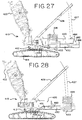
- a second basic crane model with a first counterweight set-up configuration is shown in Figures 24-28 . That same second basic crane model can be set up with a second counterweight set-up configuration, as shown in Figures 23 and 38-60 .
- Figures 17-22 show a third basic crane model set up in a counterweight set-up configuration similar to the second counterweight set-up configurations of the other basic crane models..
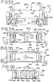
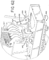
- Figures 61-62 show an alternative design for the crane of Figures 23 and 38 -60.
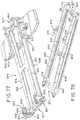
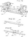
- the subsequent figures are the embodiments of the present application.
- Figures 63-72 show a fourth basic crane model set up in a first set-up configuration
- Figures 73-81 show the fourth basic model set up in a second set-up configuration
- Figures 82-89 show an alternative to the fourth basic crane model set up in the second set-up configuration.
- the mobile lift crane 10 includes lowerworks, or carbody, 12 (best seen in Figures 4 and 5 ), ground engaging members 14 elevating the carbody 12 off the ground; and a rotating bed 20 rotatably connected to the carbody 12 about an axis 2 of rotation.
- the movable ground engaging members 14 on the crane 10 are in the form of two crawlers, only one of which can be seen from the side view of Figure 1. ( Figure 1 is simplified for sake of clarity, and does not show the boom and mast.)
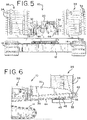
- the other ground engaging member or crawler 14 can be seen in the perspective view of Figure 4 and in the rear view of Figure 5 .
- the movable ground engaging members 14 could be multiple sets of crawlers, such as two crawlers on each side, or other movable ground engaging members, such as tires.
- the crawlers 14 provide front and rear tipping fulcrums for the crane.
- Figure 1 shows the rear tipping fulcrum 16 and the front tipping fulcrum 17 of crane 10.
- the rotating bed 20 is mounted to the carbody 12 with a slewing ring, such that the rotating bed 20 can swing about an axis 2 with respect to the ground engaging members 14.
- the rotating bed 20 supports a boom 22 pivotally mounted in a fixed position on a front portion 4 of the rotating bed 20; a live mast 28 mounted at its first end 5 on the rotating bed 20; and a movable counterweight unit 35 having one or more counterweights or counterweight members 34 on a support member 33 in the form of a counterweight tray.
- the counterweights 34 in this embodiment are provided in two stacks of individual counterweight members on the support member 33 as shown in Figures 4 and 5 .
- the rotating bed 20 has a rear-most fixed portion 3, which will be discussed in detail below.
- the counterweight unit 35 since the counterweight unit 35 is movable, it does not constitute the rear-most fixed portion 3 of the rotating bed 20, even though when the counterweight unit 35 is moved to a rearward position the outside corner of the counterweights 34 will be the furthest from the rotational axis or centerline 2 and thus define the tail swing of the crane 10. However, when the counterweight unit 35 is pulled forward, as in Figure 1 , the rear-most fixed portion 3 of the rotating bed 20 will define the tail swing of the crane 10.
- a boom hoist system 6 on crane 10 allows the angle of the boom 22 relative to a plane of rotation 7 of the rotating bed 20 to be changed.
- the plane of rotation 7 is typically perpendicular or nearly so to the axis of rotation 2.
- the boom hoist system 6 includes rigging connected between the rotating bed 20, the mast 28, and the boom 22.
- the boom hoist system 6 includes a boom hoist drum 21 and boom hoist line 27 reeved between a sheave or sheave set 8 on a second end 9 of the mast 28 and a sheave or sheave set 23 on the rotating bed 20.
- the mast 28 is pivotally connected to the rotating bed 20, and the boom hoist rigging between the mast 28 and the boom 22 comprises only fixed length members or pendants 25 (only one of which can be seen in the side view) connected between the mast 28 and a top 11 of the boom 22.
- the boom hoist rigging includes multiple parts of boom hoist line 27 between sheaves 23 on the rotating bed 20 and sheaves 8 on the second end 9 of the mast 28.
- a boom hoist drum 21 on the rotating bed 20 can thus be used to take up or pay out boom hoist line 27, changing an angle A of the live mast 28 with respect to the rotating bed 20, which in turn then changes an angle B of the boom 22 with respect to the rotating bed 20.
- mast 28 could be used as a fixed mast during normal crane operation, with boom hoist line 27 running between an equalizer and the top of the mast 28 to change an angle C between the mast 28 and the boom 22.
- a load hoist line 24 for handling a load extends from the boom 22, supporting a hook 26.
- the rotating bed 20 may also includes other elements commonly found on a mobile lift crane, such as an operator's cab 1 and whip line drum 29.
- the load hoist drum 13 for the hoist line 24 is preferably mounted on a boom butt 50 of the boom 22, as shown in Figure 2 . If desired, an additional hoist drum 19 can be mounted at a base 52 of boom 22, as shown in Figures 2 and 3 .
- the boom 22 may comprise a luffing jib pivotally mounted to the top 11 of the main boom 22, or other boom configurations.
- the counterweight unit 35 is movable with respect to the rest of the rotating bed 20.
- the rotating bed 20 includes a counterweight support frame 32, preferably in the form of a welded plate structure best seen in Figures 4-6 .
- the counterweight support frame 32 supports the movable counterweight unit 35 in a movable relationship with respect to the counterweight support frame 32.
- the counterweight support frame 32 comprises a sloped surface 54 provided by flanges 39 welded to the plate structure of the counterweight support frame 32.
- the counterweight unit 35 moves on the surface 54 if the flanges 39, the surface 54 sloping upwardly compared to the plane of rotation 7 between the rotating bed 20 and the carbody 12 as the counterweight support frame 32 extends rearwardly.
- the counterweight tray 33 includes rollers 37, which rest on the flanges 39.
- the rollers 37 are placed on the top of the counterweight tray 33 so that the counterweight tray 33 is suspended beneath the counterweight support frame 32.
- the counterweight support frame 32 constitutes the rear-most fixed portion 3 of the rotating bed 20. Further, the counterweight support frame 32 is supported on the rotating bed 20 in a fashion such that the moment generated by the counterweight unit 35 acts on the rotating bed 20 predominantly, and in this case only, through the counterweight support frame 32.
- a counterweight movement system 58 is connected between the rotating bed 20 and the counterweight unit 35 so as to be able to move the counterweight unit 35 toward and away from the boom 22.
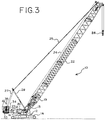
- the counterweight unit 35 is movable between a position where the counterweight unit 35 is in front of the rear-most fixed portion 3 of the rotating bed 20, such that the tail swing of the crane 10 is dictated by the rear-most fixed portion 3 of the rotating bed 20 (as seen in Figures 1 and 2 ), and a position where the counterweight unit 35 dictates the tail swing of the crane 10 (as seen in Figures 3 , 4 and 6 ).
- the counterweight unit 35 can be moved to a point so that the center of gravity of the counterweight unit 35 is near to, and preferably even in front of, the rear tipping fulcrum 16 the crane 10, as seen in Figure 1 .
- the counterweight movement system 58 in the crane 10 comprises a counterweight unit movement device 60 made up of a drive motor 40 and a drum 42 on a rear 62 of the counterweight support frame 32.
- the counterweight unit movement device 60 has two spaced apart identical assemblies, and thus the drive motor 40 drives two drums 42, best seen in Figure 4 .
- Each assembly of the counterweight unit movement device 60 further includes a flexible tension member 44 that passes around a driven pulley and idler pulley 41 (best seen in Figure 1 ).
- the driven pulleys are provided by drums 42.
- the flexible tension member 44 may be a wire rope as shown, or a chain. Of course if a chain is used, the driven pulley will be a chain drive.
- each flexible tension member 44 are connect to the counterweight tray 33 as seen in Figure 6 , so that the counterweight unit 35 can be pulled both toward and away from the boom 22.
- this is accomplished by having an eye 43 on both ends of the flexible tension member or wire rope 44 and holes in a connector 45 on the counterweight tray 33, with pins through the eyes 43 and the connector 45.
- the counterweight unit movement device 60 is connected between the counterweight support frame 32 and the counterweight unit 35.
- Figure 1 shows the counterweight unit 35 in its most forward position
- Figure 2 shows the counterweight unit 35 in a mid-position
- Figures 3-6 show the counterweight unit 35 in its most rearward position, such as when a large load is suspended from the hook 26, or the boom 22 is pivoted forward to extend a load further from the rotating bed 20.
- the crane 10 is configured such that during crane operation, when the counterweight unit 35 is moved to compensate for changes in the combined boom and load moment, the weight of the counterweight unit 35 is transferred to the rotating bed 20 only through the counterweight support frame 32.
- the movable counterweight unit 35 is never supported by the ground during normal operations.
- the crane can performing a pick, move and set operation with a load wherein the movable counterweight unit 35 is moved toward and away from the front portion 4 of the rotating bed 20 by operating hydraulic motor 40 and drums 42 to move the counterweight unit 35 during the crane operation to help counterbalance the load, but the counterweight unit 35 is never supported by the ground other than indirectly by the movable ground engaging members 14 on the carbody 12.
- the movable counterweight unit 35 is the only functional counterweight on the crane 10.
- the carbody 12 is not provided with any separate functional counterweight.
- the counterweight unit 35 can be moved very near to the centerline of rotation 2 of the crane 10 means that the counterweight does not produce a large backward tipping moment in that configuration, which would otherwise require the carbody to carry additional counterweight.
- the phrase "not provided with any separate functional counterweight” is meant to differentiate prior art cranes where the carbody is specifically designed to include significant amounts of counterweight used to prevent backward tipping of the crane. For example, on a standard model 16000 crane from the Manitowoc Crane Company, the carbody is provided with 120,000 pounds of counterweight, and the rotating bed is provided with 332,000 pounds of upperworks counterweight. With cranes of the present invention, all 452,000 pounds of that counterweight could be used in the movable counterweight unit 35, and no functional counterweight added to the carbody 12.
- the positioning of the counterweight unit 35 may be manually controlled, or the crane 10 can further comprise a sensor (not shown) that senses a condition that is related to a need to move the counterweight unit 35.
- the counterweight unit 35 may be moved in response to a change of boom angle B.
- the combined boom and load moment can be used to control movement of the counterweight unit 35, so that either a change in boom angle B, or picking up a load, will result in movement of the counterweight unit 35. If desired, this can be accomplished automatically if a computer processor is coupled with the sensor.
- a computer processor controlling the counterweight movement system 58, and possibly other operations of the crane receives signals from the sensor indicating the condition (such as the boom angle B), or some other function indicative of the condition (such as tension in the boom hoist rigging, which is indicative of the combined boom and load moment, or the moment of the boom 22 and load about the hinge pins of the boom 22) and controls the position of the counterweight unit 35.
- the position of the counterweight unit 35 may be detected by keeping track of the revolutions of drums 42, or using a cable and reel arrangement (not shown).
- the crane 10 using such a system will preferably comprise a computer readable storage medium comprising programming code embodied therein operable to be executed by the computer processor to control the position of the counterweight unit 35.
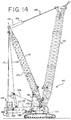
- FIGs 13-15 show a second embodiment of a crane 110 of the present invention.
- this embodiment includes a fixed position mast 117, which has some disadvantages compared to the crane 10 since the fixed mast structure requires additional components to be delivered to a job site, and the fixed mast 117 sometimes requires clearing potential obstacles when the crane is repositioned.
- the addition of the fixed mast 117 allows the crane 110 to be equipped with other features that increase the lifting capacity of the crane 110.
- the carbody 112 is not provided with any separate functional counterweight, and the movable counterweight unit 135 is never supported by the ground during crane pick, move and set operations other than indirectly by movable ground engaging members 114 on the carbody 112.
- Crane 110 is made with the same basic crane structure of crane 10, but has an additional counterweight support beam 160 added to it, as well as the fixed mast 117. Instead of a fixed mast, a derrick mast could also be used.
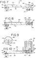
- the counterweight support beam 160 is shown in Figures 7-12 .
- the counterweight support beam 160 is moveably connected to the rotating bed 120.
- the crane 110 utilizes the same structure that moved the counterweight unit 35 on crane 10 as a counterweight support beam movement device, as explained below.
- the counterweight movement system includes a counterweight unit movement device and a counterweight support beam movement device.
- This counterweight support beam movement device is connected between the counterweight support beam 160 and the rotating bed 120 such that the counterweight support beam 160 can be moved with respect to the length of the rotating bed 120 away from the rotational connection of the rotating bed 120 and the carbody 112, and extended rearwardly of the rear-most fixed portion 103 of the rotating bed 120.
- the movement of the counterweight support beam 160 is generally horizontal and in a direction in line with the length of the counterweight support beam 160.
- the crane 110 further includes a tension member 131 connected between the fixed mast 117 and the counterweight support beam 160.
- the counterweight unit 135 is supported on the counterweight support beam 160 in a movable relationship with respect to the counterweight support beam 160.
- the counterweight unit movement device is connected between the counterweight support beam 160 and the counterweight unit 135 so as to be able to move the counterweight unit 135 toward and away from the boom 122.
- the counterweight unit 135 may be moved to and held at a position in front of the top 170 of the fixed mast 117 and moved to and held at a position rearward of the top 170 of the fixed mast 117.
- Crane 110 includes a live mast 128 just like live mast 28 on crane 10. However, after being used to erect the fixed mast 117, live mast 128 is thereafter disabled from changing position.
- boom hoist line 115 travels up from boom hoist drum 118 mounted at the base 192 of mast 117 and is reeved with multiple parts of line between an equalizer 129 and sheaves 174 on the top 170 of fixed mast 117.
- the equalizer 129 is connected to the boom 122 by fixed length pendants 126.
- Fixed length pendants 125 connect the top 170 of fixed mast 117 to the top 175 of mast 128.
- crane 110 also includes a load hoist line and hook block, just like those used in crane 10.
- the counterweight support beam 160 is preferably in a U-shape when viewed from above and made from two spaced apart side members 162 connected together in the rear 177 by a cross member 164, best seen in Figure 12 .
- the front ends 171 of the two side members 162 connect to a counterweight tray 133, which is moveably mounted on a counterweight support frame 132 on rotating bed 120 using drive motor and drums on the rear of the rotating bed. This is identical to the way counterweight tray 33 is moveably mounted to the rotating bed 20 on crane 10.
- the counterweight support beam 160 is further equipped with a counterweight unit movement device connected between the counterweight support beam 160 and the counterweight unit 135.
- the counterweight unit 135 can thus move with the counterweight support beam 160, and move relative to the counterweight support beam 160.
- the tension member 131 is preferably in the form of two sets of connected flat straps (only one set of which can be seen in the side views) attached adjacent the top 170 of the fixed mast 117 and supports the rear of counterweight support beam 160 in a suspended mode. Since the tension member 131 has a fixed length, when the counterweight support beam 160 is moved rearwardly, the rear of the counterweight support beam 160 will move in an arc, with the center of arc being the point where tension member 131 connects to the top 170 of fixed mast 117. Thus, the rear 181 of the counterweight support beam 160 will rise slightly as it moves rearwardly.
- the surface 154 on the flange 139 on the counterweight support frame 132 on the rotating bed 120 on which the counterweight tray 133 moves rearwardly comprises a sloped surface that slopes upwardly compared to the plane of rotation 107 between the rotating bed 120 and the carbody 112 as the counterweight support beam 160 is moved rearwardly, just as flanges 39 provided the sloped surface 54 on crane 10.
- the path could be machined to match the arc shape traveled by the rear of the counterweight support beam 160 but, more practically, a simple straight sloped path is used that provides the same raise in height that the rear 181 of the counterweight support beam 160 will experience as the counterweight support beam 160 is moved to its full rearward position.
- the movement of the counterweight support beam 160 is thus generally horizontal and in a direction in line with the length of the counterweight support beam 160.
- rollers 137 are mounted on the counterweight tray 133 such that the rear rollers 137 are at a higher elevation than the front rollers 137 ( Figure 7 ). In this manner the counterweight tray 133 will itself remain horizontal while the rollers 137 ride on the sloped surface 154.
- Support feet 182 are included as a safety feature and can provide support to the counterweight unit 135 in the event of a sudden release of the load.
- the same structure that moved the counterweight tray 33 in crane 10 is used to move the counterweight tray 133 in crane 1 10.
- the counterweight support beam 160 since the counterweight support beam 160 is now connected to the counterweight tray 133, the counterweight support beam 160 now moves with the counterweight tray 133.
- the counterweight support beam 160 can thus be moved to and secured at infinitely variable positions with respect to the rotating bed 120, meaning that it can be moved a small amount, a large amount (up to the maximum movement of the counterweight tray 133 on the counterweight support frame 132 on the rotating bed 120), or any position there between.
- This is different than other extendable counterweight support surfaces, such as counterweight support beam 84 in U.S. Patent No. 4,953,722 , which can be extended and secured at only two different operational positions.
- Figure 9 shows the connection of the counterweight support beam 160 to the counterweight tray 133.
- the individual counterweights 134 are not placed on the counterweight tray 133 in this embodiment.
- Lugs 179 welded to the side members 162 connect to connectors 145 on the counterweight tray 133.
- a flexible tension member 144 such as wire rope, is used to move the counterweight tray 133, and an eye 143 on both ends of wire rope 144 and holes in connector 145 on the counterweight tray 133 are pinned together with pins through the eyes 143 and the connector 145. At the same place, a pin holds each lug 179 to a connector 145.
- the sections of counterweight 134 are stacked on the counterweight support beam 160 in a movable manner, such as on sliding wear pads (not shown). When they are in a far forward position, the counterweight sections 134 are directly above the counterweight tray 133, to which the counterweight support beam 160 is attached. In this position, just like the counterweight 35, counterweight unit 135 is movable to a position in front of the rear-most fixed portion 103 of the rotating bed 120.
- the counterweight unit 135 may be moved to and held at a first position in front of the top 170 of the fixed mast 117, and moved to and held at a second position rearward of the top 170 of the fixed mast 117.
- the counterweight unit 135 comprises two stacks 138 of counterweights 134 that are moved simultaneously.
- the stacks 138 each contain the same counterweights 134 that are identical to the counterweights 34 used on crane 10, plus some additional counterweights 136 ( Figures 10 and 11 ).
- the stacks 138 each rest on a counterweight base plate 163, which in turn includes slider pads (not shown) that allow the counterweight base plates 163 to move on a surface 165 of the side members 162. Rollers could be used instead of slider pads.
- the chain drives 176 are mounted on shafts 178 which are turned by a gear box and motor (not shown).
- the counterweight base plates 163 each attach to these flexible tension members 173 through a connector 189 so that the stacks 138 of counterweight 134 and/or 136 can be pulled both toward and away from the front 180 of the counterweight support beam 160, and hence toward and away from the boom 122. (The counterweight base plates 163 are not shown in Figure 12 for sake of clarity).
- the crane 110 thus includes a movable a counterweight support beam 160 and a movable counterweight unit 135 supported on the movable counterweight beam 160; the movable counterweight unit 135 can be moved independently on the counterweight support beam 160.
- the angle B' of the boom 122 can be changed, or the crane 110 can perform a pick, move and set operation with a load, wherein the movable counterweight unit 135 is moved toward and away from the front portion 104 of the rotating bed 120 during the boom angle change or pick, move and set operation to help counterbalance the combined boom and load moment.
- the counterweight unit 135 will move to the rear 103 of the crane 110 while the counterweight support beam 160 remains in its forward position.
- the counterweight unit 135 can stay on the counterweight support beam 160 during the change in the combined boom and load moment, and the counterweight support beam 160 and counterweight unit 135 can move together to counterbalance the crane 110 as the boom angle B' is lowered or a load is picked up. As with crane 10, the counterweight unit 135 can move forward of the rear-most fixed portion 103 of the rotating bed 120.
- the basic crane 10 can be used to make the crane 110, one aspect of the invention is a crane that is configured to be set up with two different counterweight set-up configuration options.
- the first counterweight set-up configuration option (crane 10) has a first counterweight movement system that can move a first counterweight unit 35 between a first position ( Figure 1 ) and a second position ( Figure 3 ).
- the counterweight set-up configuration is a counterweight unit 35 directly supported on the counterweight support frame 32 and the counterweight unit movement device is connected so as to move the counterweight unit with respect to the counterweight support frame.
- the first position is a position in which the first counterweight unit is as near as possible to the axis of rotation for the first counterweight set-up configuration option.
- the second position is a position in which the first counterweight unit is as far as possible from the axis of rotation for the first counterweight set-up configuration option. This distance constitutes a second distance from the axis of rotation.
- the second counterweight set-up configuration option has a second counterweight movement system that can move a second counterweight unit 135 between a third position ( Figure 13 ) and a fourth position ( Figure 15 ).
- the counterweight set-up configuration includes a counterweight support beam 160 moveably connected to the counterweight support frame 132 and a counterweight unit 135 supported on the counterweight support beam, with the counterweight support beam movement device connected so as to move the counterweight support beam with respect to the counterweight support frame.
- the third position is a position in which the second counterweight unit is as near as possible to the axis of rotation for the second counterweight set-up configuration option. This constitutes a third distance from the axis of rotation.
- the fourth position is a position in which the second counterweight unit is as far as possible from the axis of rotation in the second counterweight set-up configuration option, which constitutes a fourth distance from the axis of rotation.
- the fourth distance is greater than the second distance, and the difference between the third and fourth distances is greater than the difference between the first and second distances.
- the difference between the third and fourth distances is preferably at least 1.5 times as large as the difference between the first and second distances, more preferably at least 2.0 times as large as the difference between the first and second distances, and even more preferably at least 2.5 times as large as the difference between the first and second distances.
- the difference between the third and fourth distances is at least 3 times as large as the difference between the first and second distances.
- the crane 10 includes a counterweight tray 33 movably supported on the counterweight support frame 32, and in the first option counterweights 34 are stacked directly on the counterweight tray 33, and in the second option the counterweight support beam 160 is attached to the counterweight tray 133 and counterweights 134 are stacked on the counterweight support beam 160.
- the second counterweight unit will typically have more counterweight boxes included than the first counterweight unit. However, while not shown in the depicted embodiments, the first and second counterweight units could be identically configured.
- Figure 16 shows a third embodiment of a crane, which is just like crane 110 in all but one feature.
- the reference numbers used on the parts of crane 210 in Figure 16 are identical to the parts of the crane 110 with the same reference number with an addend of 100.
- boom 222 on crane 210 is just like boom 122 on crane 110.
- boom hoist line 215, fixed mast 217, boom hoist drum 218 rotating bed 220, drum 221, sheave set 223, fixed length pendants 225, fixed length pendants 226, mast 228, equalizer 229, tension member 231 and counterweight unit 235 are just the same as their respective components in crane 110.
- the one difference is that crane 210 includes an additional counterweight unit 237 attached to the rear of the counterweight support beam 260.
- the additional counterweight unit 237 is used to further increase the lifting capacity of the basic crane 10. It moves in and out with the counterweight support beam 260.
- FIG 16A shows the details of how the auxiliary counterweight attaches to the counterweight support beam 260.
- the auxiliary counterweight 237 includes a counterweight tray 252 which is provided with side panels 254 that include a hook element 256.
- the counterweight support beam 260 is provided with extensions 266 on the rear side of cross member 264, which mate with the side panels 254.
- a pin 268 in each extension 266 allows the hook element 256 to connect to the pin 268 from above, with a rotational engagement.
- Each side panel 254 is provided with a bearing surface 258, and the cross member 264 is provided with a bearing surfaces 269 that abut the surfaces 258 to limit the rotation when the hook element 256 is engaged with the pin 268, thus holding the tray 252 in a connected, horizontal position.
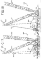
- FIGS 17-22 show a fourth embodiment of a crane 310 of the present invention.
- crane 310 includes a carbody 312, crawlers 314, rotating bed 320, boom 322, boom hoist rigging 325, a fixed mast 317, a live mast 328, a counterweight support beam 360 moveably connected to the rotating bed such that the rear portion of the counterweight support beam 360 can be extended away from the rotational connection of the rotating bed 320 and the carbody 312, a counterweight unit 335 supported on the counterweight support beam 360 in a movable relationship with respect to the counterweight support beam, and a tension member 331 connected between the fixed mast and the counterweight support beam 360.
- the primary difference between the crane 310 compared to crane 110 is that the counterweight support beam 360 has a telescoping feature, and the front portion of it stays connected to the rotating bed 320 at the same place all of the time. Further, the counterweight movement system simultaneously causes the counterweight unit 335 to move rearwardly with respect to the counterweight support beam 360 as the telescoping rear portion of the counterweight support beam moves rearwardly with respect to the rotating bed 320. In this fashion a single driving device moves the counterweight support beam with respect to the rotating bed (serving as the counterweight support beam moving device) and moves the counterweight unit with respect to the counterweight support beam (serving as a counterweight unit movement device).
- the counterweight support beam 360 is preferably in a U shape, made from two spaced apart side members 362, connected together in the rear by a cross member 364, best seen in Figure 20 .
- the front ends of the two side members 362 connect to the rotating bed 320.
- Each side member 362 is made from two sections that fit together in a telescoping fashion.
- Figure 17 shows the two sections in a retracted position, while Figures 18-21 show the two sections in an extended position.
- FIG 19 which shows the counterweight support beam 360 by itself, with the counterweight unit 335 resting on it
- Figure 20 which shows the counterweight support beam 360 connected to the rotating bed 320 of crane 310 but with other portions of crane 310 removed for sake of clarity, shows the counterweight support beam movement device.
- the counterweight support beam movement device comprises a telescoping cylinder 355 attached between the rotating bed 320 and the counterweight support beam 360, and a plurality of flexible tension members in the form of wire ropes 373 that pass around pulleys 371 and 372 and which connect to the counterweight unit 335 at connections 376 and to the counterweight support beam 360 at connections 378.
- the counterweight unit 335 can be pulled toward the boom as the telescoping cylinder 355 retracts and pulls the rear portion 364 of the counterweight support beam towards the boom.
- the pulleys 372 on the counterweight support beam 360 have to also move forward. Since the wire ropes 373 are connected at both the connections 376 and 378, in order for the pulleys 372 to move forward, the wire rope has to travel in a clockwise fashion (as seen from the side view in Figure 21 ), which moves the connection 376 forward, which in turn pulls the counterweight unit 335 forward on the counterweight support beam, in addition to the movement of the section of the counterweight support beam itself.
- the rotating bed 320 has a rear-most fixed portion, and the counterweight unit 335 is movable to a position where the counterweight unit 335 is in front of the rear-most fixed portion of the rotating bed.
- the counterweight unit 335 may be moved to and held at a position in front of the top of the fixed mast ( Figure 17 ) and moved to and held at a position rearward of the top of the fixed mast ( Figure 18 ) during crane pick, move and set operations.
- the movable counterweight unit 335 is never supported by the ground other than indirectly by the movable ground engaging members 314 on the carbody 312.
- the support feet 382 are included as a safety feature and can provide support to the counterweight unit in the event of a sudden release of the load.
- the support feet 382 are sized so that when the rear 364 of the counterweight support beam 360 is positioned directly below the top of the mast 317 ( Figure 17 ), and thus support feet 382 are at their closest point to the ground in the arc created by pivoting the tension member 331 about the top of the mast 317, the support feet 382 will still be an adequate distance off the ground so that during normal crane operation, the support feet never contact the ground during pick, move and set operations.
- Figures 23-60 show the details of another embodiment of a crane that can be set up with two different counterweight set-up configurations.
- Figures 24-28 show the crane 410 with a movable counterweight supported on a counterweight support frame.
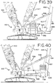
- Figures 23 and 38-41 show the same crane with a mast and a movable counterweight support beam. In this configuration the crane is referred to as crane 510.
- crane 410 has a carbody 412; movable ground engaging members 414 mounted on the carbody 412 allowing the crane 410 to move over the ground; a rotating bed 420 rotatably connected to the carbody 412 about an axis of rotation; a boom 422 pivotally mounted about a fixed boom hinge point on the front portion of the rotating bed; and a boom hoist system, provided by a live mast 428 and boom hoist rigging 427, connected between a sheave set on the rotating bed and the boom that allows the angle of the boom relative to the plane of rotation of the rotating bed to be changed.
- the boom hoist system comprises a boom hoist drum and boom hoist line reeved between a sheave set on the mast and a sheave set on the rotating bed.
- the rotating bed includes a counterweight support frame 432 that is attached to the remainder of the rotating bed 420 in a detachable fashion, as described in more detail below.
- the counterweight unit 435 is supported on the counterweight support frame 432 in a movable relationship with respect to the counterweight support frame 432.
- a counterweight unit movement device also described in more detail below, connects between the rotating bed and the counterweight unit 435 so as to be able to move the counterweight unit 435 toward and away from the boom 422.
- the moment generated by the counterweight unit 435 acts on the rotating bed predominantly, and in this case only, through the counterweight support frame.
- the counterweight support frame 432 in this embodiment is located below the remainder of the rotating bed.
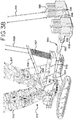
- the counterweight support frame is made of a welded plate structure, best seen in Figures 29-34 . It is mounted in a removable fashion to the remainder of the rotating bed.
- An adapter 450 is used to make an easily removable connection between the rotating bed 420 and the front of the counterweight support frame 432.
- the adapter 450 includes holes 452 through ears 454 that fit between lugs 429 on the lower portion of the rotating bed 420 to connect the adapter 450, and hence the counterweight support frame 432, to the rotating bed 420.
- the adapter 450 is itself secured to the counterweight support frame 432 by pins 456 (best seen in Figure 34 ).
- pins 456 allows the adapter 450 to be detached from the counterweight support frame 432 so that the counterweight support frame 432 can be reused in the configuration of crane 510.
- Front holes 481 serve as a place to pin the counterweight support frame 432 and adapter 450 together.
- Rear holes 483 and top holes 484 in the counterweight support frame 432 are not used in this embodiment, but are included so that the counterweight support frame 432 can be used in the configuration of crane 510, as explained below.
- the counterweight support frame 432 connects to the rotating bed through two short links 462.
- the links 462 are each pinned at one end to a lug 464 on the rotating bed and at the other end in between a pair of lugs 466 on the rear of the counterweight support frame 432.
- the counterweight unit movement device is connected between the rotating bed 420 and the counterweight unit 435 by being connected between the counterweight support frame 432, as part of the rotating bed, and the counterweight unit.
- the counterweight unit 435 comprises a counterweight tray 433 pinned to a movable trolley 470 ( Figures 35-37 ). As with earlier embodiments, the counterweight tray is suspended beneath the counterweight support frame.
- the tray 433 pins into holes 471 ( Figure 31 ) on the trolley 470.
- the holes 471 are bigger on top than on bottom.
- the bottom dimension is the same as the outside diameter of the pins (not shown) used to connect the tray 433 and the trolley 470. The larger dimension on top allows for easy insertion of the pins.
- the trolley 470 rides on four vertical rollers 476 that engage a flange 438 along each side of the counterweight support frame 432.
- the trolley 470 also includes four horizontal rollers 478 ( Figure 33 ) that provide sideways positioning of the trolley 470 on the counterweight support frame 432.
- the counterweight unit movement device comprises at least one, and in this embodiment, two hydraulic motors and gear boxes 472 each driving a gear 474 connected to the trolley 470.
- the counterweight support frame 432 includes a set of teeth 436 ( Figure 29 ) on each side.
- the gears 474 engage with the teeth 436 on the two sides of the counterweight support frame 432 to move the trolley 470 with respect to the counterweight support frame as the motor and gearbox 472 turns the gear 474.
- the counterweight unit 435 can move with respect to the counterweight support frame 432 by being mounted on trolley 470.
- steel bar 434 may be bolted onto the rest of the counterweight support frame 432 with socket head cap screws to provide both flange 438 and the teeth 436.
- the side surfaces of these steel bars provide the engagement surface for the horizontal rollers 478, as seen in Figure 33 .
- the surfaces of these steel bars 434 are hardened to provide better wear resistance with the rollers 476 and 478.
- the steel bars 434 include shear blocks surfaces 439 ( Figures 32 and 33 ) to help carry the load from the rollers 476 on the trolley 470 to the counterweight support frame 432.
- the rollers 476 are preferably mounted in the same vertical plane as the gears 474.
- the crane is configured such that during crane operation, when the counterweight unit is moved to compensate for changes in the combined boom and load moment, the moment generated by the counterweight unit with respect to a front tipping fulcrum of the crane is not transferred to the rotating bed through the mast. Rather, the moment is transferred to the rotating bed by the counterweight support frame, such as through the pinned connections at lugs 429 and 464.
- the crane 510 is made from the same components used to make crane 410, with an added fixed mast 517 and a movable counterweight support beam 560.
- the structure used as the live mast 428 in crane 410 is no longer used as a live mast.
- boom hoist rigging 519 is provided between the boom top and the top of fixed mast 517 to allow the boom angle to be changed.
- Fixed length pendants 525 connect the top of fixed mast 517 to the top of mast 528.
- the rigging 527 and the mast 528 are held in a fixed position during normal operation of crane 520.
- a tension member 531 is added between the top of mast 517 and counterweight support beam 560.
- the components used on the crane 410 that are the same as in crane 510 have the same reference number with an addend of 100; thus boom 422 on crane 410 is boom 522 on crane 510.
- the counterweight unit 535 is the same as counterweight unit 435.
- counterweight unit 535 on crane 510 may be moved in two ways.
- counterweight unit 535 includes a trolley 570 with rollers 576 that ride on flanges on a counterweight support frame 532.
- the counterweight support frame 532 is part of the telescoping counterweight support beam 560.
- another way to move the counterweight unit 535 is to telescope out the beam 560 while maintaining the location of the counterweight unit 535 on the frame 532.
- the first type of movement can be seen by comparing Figures 39 and 40
- the second type of movement can be seen by comparing Figures 40 and 41 . Both types of movement can be carried out independently, and need not be carried out to the full extent possible.
- the counterweight unit 535 will be moved back on frame 532 until it has moved as far as possible before the beam 560 is extended.
- the counterweight unit can be moved to a position where it is between the boom hoist sheave set on the rotating bed and the axis of rotation of the carbody 512, and moved to a position where it is behind the boom hoist sheave set on the rotating bed.
- the counterweight support beam 560 is preferable made with three nested, telescoping beam members: an inner beam member 592, a middle beam member 582 and an outer beam member 532, also referred to above as the counterweight support frame 532.
- the counterweight support beam movement device comprises a telescoping frame with at least one inner frame member fitting inside an outer frame member.
- the counterweight support beam has an intermediate frame member inside the outer frame member and surrounding the inner frame member.
- the counterweight support beam comprises the outer frame member of the telescoping frame that is part of the counterweight support beam movement device.
- the structure used as the counterweight support frame 432 in the first counterweight set-up configuration option can be used as the outer beam member 532 in the counterweight support beam 560 in the second counterweight set-up configuration option (crane 510).
- the counterweight support frame 432 when used as the outer beam member 532, it includes additional internal structure so that it can be connected to the rest of the beam members and move with respect to the rotating bed 520.
- the trolley 570 is just the same as trolley 470, and the outer beam member 532 has an external configuration like counterweight support frame 432, the way that counterweight unit 535 moves with respect to outer beam member 532, the structure of the trolley 570, motors and gearboxes 572 and gears 574 engaging teeth on sections of steel bar 534 will not be described again in detail. Because of these similarities, in this embodiment the driving gear connected to the trolley engages teeth on the counterweight support beam 560 to move the trolley with respect to the counterweight support beam 560 as the motor turns the gear 574.
- the counterweight support beam 560 mounts to the rest of the crane 510 in a fashion similar to how counterweight support frame 432 connected to the rest of crane 410. Instead of short links 462, connecting between lugs 466 and the rear of the rotating bed, the tension members 531 connect from the top of the fixed mast 517 through lugs 566 to the rear of the counterweight support beam 560.
- the inner beam member 592 includes a connector 550 on its end. This connector has ears 554 with holes 552 through them so that the connector 550 can be pinned to the underside of the rotating bed 520, just as adapter 450 was pinned to rotating bed 420.
- the counterweight support beam movement device comprises a linear actuation device, preferably in the form of a trunnion mounted hydraulic cylinder.
- the counterweight support beam movement device further comprises ropes and pulleys mounted to the intermediate and outer frame members such that the outer frame member moves in a slave relationship to the movement of the intermediate frame member with respect to the inner frame member.
- a double acting hydraulic cylinder 540 with a rod 542 is connected between the inner beam member 592 and the middle beam member. Thus as the rod 542 is extended and retracted, the middle beam member 582 moves with respect to the inner beam member 592.
- the outer beam member 532 is connected to the other beam members in a slaved fashion, so that movement of the other beam members with respect to each other necessarily and simultaneously causes a movement of the outer beam member 532 with respect to the middle beam member 582.
- the details of how this happens are best seen in Figures 42-52 , with additional details in Figures 53-60 .
- the inner, middle and outer beam members are each made from welded plates into a box structure. Rollers 585 and 586 support the inside surface of outer beam member 532 on the outside of middle beam member 582. Likewise, rollers 587 and 588 support the inside of middle beam 582 to the outside of inner beam member 592.
- the holes 481 and 483 in the sides of counterweight support frame 432 are used to mount rollers 585 and 586 when the member 432 is reused as outer beam member 532 in crane 510.
- the movement of the outer beam member 532 is controlled by a pair of retract wire ropes 544 and a pair of extend wire ropes 546.
- the extend wire ropes 546 are tied off at one end by connectors 545 to the front of the outer beam member 532.
- the extend wire ropes pass through holes 584, which are the same as unused holes 484 in the counterweight support frame 432.
- the extend wire ropes 546 pass around extend sheaves 596 mounted on the rear portion of the middle frame member 582. The other ends of the extend wire ropes 546 are tied off by connectors 595 to the back of the counterweight support beam connector 550 located at the front of the inner beam member 592.
- the extend sheaves 596 will be pushed backward with the middle beam member, requiring the extend wire ropes 546 to pass around the extend sheaves 596, necessarily pulling the front of the outer beam member 532 backward by the connections 545. Because the extend wire ropes 546 are tied off at connectors 545 on the outer beam member 532 and connectors 595 at the front of the inner beam member 592, but pass around extend sheaves 596 attached to the middle beam member 582, one foot of travel distance of the middle beam member will cause the outer beam member 532 to extend two feet.
- the retract wire ropes 544 are tied off at one end by connectors 543 ( Figures 49 and 56 ) to the rear of the inner beam member 592.
- the retract wire ropes pass around retract sheaves 594 mounted on the front portion of the middle beam member 582.
- the other ends of the retract wire ropes 544 are tied off by connectors 593 to the back of the outer member 532. If the counterweight support beam 560 is in an extended mode, and the hydraulic cylinder 540 is retracted, causing the middle beam member 582 to move forward with respect to the inner beam member 592, the retract sheaves 594 will be pushed forward with the middle beam member, requiring the retract wire ropes 544 to pass around the retract sheaves 594, necessarily pulling the rear of the outer beam member forward by the connectors 593.
- retract wire ropes are tied off at connectors 543 to the inner beam member, but pass around retract sheaves 594 attached to the middle beam member 582, one foot of travel distance of the middle beam member will cause the outer beam member 532 to retract two feet.
- the retract wire ropes 544 could attach to the outer beam member 532 at any point in the beam behind where the retract sheaves 594 are located when the beam is retracted. However, by having the retract wire ropes 544 tie off at the very rear of the outer beam member 532, the connectors 593 are more readily accessible if adjustment is needed.
- rollers 588 have flanges on the outside to help keep the beams aligned side-to-side.
- Rollers 585, 586 and 587 also have such flanges.
- the rollers 585, 586, 587 and 588 are mounted in the side of the middle beam member 582 with bearings between the roller shaft and the roller, although no bearings are shown in the figures. Also, it is not clear from the drawings, but one of ordinary skill in the art will understand that there is a slight clearance on the sides and the top or bottom of the rollers compared to the beam members supported thereon.
- Figures 61 and 62 show an alternative arrangement for the connection between the rear of the rotating bed 420 and the counterweight support frame 432 when the crane is set up without the fixed mast 517 (when the crane is set up in its first counterweight set-up configuration), as well as an alternative arrangement for the connection between the telescoping counterweight support beam 560 and the tension members 531 when the crane is set up in its second counterweight set-up configuration.
- the support on the rear of the rotating bed in the form of lugs 523 are located at a position where they can be pinned directly to lugs 620 on outer beam member 532, used as part of counterweight support beam 560 in the embodiment shown in Figures 61 and 62 .
- lugs 620 are each made of two plates with holes through them used for making a pinned connection with either the rotating bed (when the crane is set up in its first counterweight set-up configuration), or the bottom of a tension member 531 (when the crane is set up in its second counterweight set-up configuration).
- pins In the first counterweight set-up configuration, pins (not shown) pass through holes 632 in the lugs 620 and holes 562 in the lugs 523.
- the lugs 620 include a top bar 624 and lower bar 626 between plates 621 and 622 that engage with the lug 523 on rotating bed 520 when the counterweight support beam 560 is fully retracted, as shown in Figure 62 (where the left side plate has been removed for sake of clarity).
- the support 523 on the rear of the rotating bed engages with a counterweight beam support engagement (bars 624) positioned such that when the counterweight beam is in a fully retracted position, the support and the support engagement are able to transfer load from the counterweight beam directly to the rotating bed.
- the moment of the counterweight system may exceed the offsetting moment of the combined boom and load moment as seen by the fixed mast 517.
- the fixed mast will try to move backward and will compress the fixed mast stops 529 until the top bars 624 on the outer beam member lugs 620 engage the lug 523 on the rotating bed 520.
- no pins are placed in holes 562 and 632. These holes just also happen to line up when the tension member 531 is pinned to the lugs 620 and the counterweight support beam 560 is fully retracted.
- the rear of the rotating bed will be carrying part of the counterweight load, reducing the tendency of the mast 517 to tip backwards any further.
- some embodiments of the crane utilize an active control system.
- encoders or other position and load sensors send signals reflective of the mast position, the counterweight position, the load on the hook, the counterweight load, and other parameters to a controller, such as a general or specific purpose computer programmed to receive such data.
- a control or stability program evaluates the data and, given the circumstances and if the counterweight is positioned sufficiently close to the rear-most fixed portion of the carbody, the controller will provide a signal to move the live mast 517 slightly rearward.
- the tension member 531 moves relatively downward, thereby lowering the counterweight support beam 560, the connected counterweight unit 535, and, of course, the counterweight support bars 620 onto the support 523. This, in turn, transfers a portion of the load of the counterweight unit 535 from the tension member 531 onto the rotating body 520 via the supports 523.
- the counterweight unit is movable to a position so that the center of gravity of the counterweight unit is within a distance from the axis of rotation of less than 125% of the distance from the axis of rotation to the rear tipping fulcrum, and more preferably within a distance from the axis of rotation of less than 110% of the distance from the axis of rotation to the rear tipping fulcrum.
- variable position counterweight of the preferred crane has only one counterweight assembly.
- the crane 10 with a single variable position counterweight will require approximately 70% of this amount, or 230 metric tonne of counterweight, to develop the same load moment.
- the 30% counterweight reduction directly reduces the cost of the counterweight, although this cost is partially offset by the cost of the counterweight movement system.
- 100 metric tonne of counterweight requires five trucks for transport.
- reducing the total counterweight reduces the number of trucks required to transport the crane between operational sites. Because the counterweight is reduced significantly, the maximum ground bearing reactions are also reduced by the same amount.
- the counterweight is positioned only as far rearward as required to lift the load.
- the crane and counterweight remain as compact as possible and only expand when additional load moment is required.
- a further feature is the capability to operate with reduced counterweight in the mid-position.
- the reduced counterweight would balance the backward stability requirements when no load is applied to the hook.
- the variable position function could then be turned off and the crane would operate as a traditional lift crane.
- the total counterweight compared to a crane with a comparable capacity can be reduced, or if the total counterweight is the same, the stability of the crane can be increased or the crane can be designed with a smaller footprint.
- some combination of all three of these advantages may be used in producing a new crane model.
- a crane customer may initially decide to purchase and use the crane 410 with only the counterweight support frame 432, and not include an inner beam member 592 and middle beam member 582, nor the fixed mast 517. Then later the crane 410 could be converted to crane 510 by adding the fixed mast 517 and inserting the inner beam member 592 and middle beam member 582 into the counterweight support frame 432, making the counterweight support beam 560. Thereafter, inner beam member 592 and middle beam member 582 could be removed when the crane was set up without the fixed mast 517. However, it is more likely that the counterweight support beam 560 would remain intact once assembled, and used on the crane 410 without being extended, but simply used as a counterweight support frame 432.
- the counterweight unit In the first counterweight set-up configuration option (crane 10 or crane 410), the counterweight unit is not supported by a fixed mast or a derrick mast. Rather, the counterweight unit is supported on a counterweight support frame on the rotating bed.
- a counterweight movement system comprises a counterweight unit movement device connected so as to move the counterweight unit with respect to the counterweight support frame.
- the second counterweight set-up configuration option (crane 110 or crane 510)
- the second counterweight unit In the second counterweight set-up configuration option (crane 110 or crane 510), the second counterweight unit is supported by a mast selected from a fixed mast and a derrick mast.
- a counterweight support beam is moveably connected to the rotating bed and the counterweight unit is supported on the counterweight support beam.
- the counterweight movement system comprises a counterweight support beam movement device connected so as to move the counterweight support beam with respect to the rotating bed.
- the counterweight support beam is moveably connected to the rotating bed by being moveably connected to the counterweight support frame.
- the counterweight support beam is moveably connected to the rotating bed by having a telescoping section that moves is moveably connected to the rotating bed by a front portion of the counterweight support beam.
- the crane 10 or crane 410 includes a counterweight tray movably supported on the counterweight support frame and counterweights are stacked directly on the counterweight tray.
- the counterweight support beam is attached to the counterweight tray and counterweights are stacked on the counterweight support beam by being stacked on a base plate that is on the counterweight support beam.
- each may incorporate some or all of the features as described above. Any elements from each of the earlier embodiments discussed earlier that are not expressly discussed are incorporated and included as if reprinted here.
- FIGS 63-72 illustrate another embodiment that is similar to the crane 10 with the differences now explained.
- a mobile lift crane 710 includes lowerworks, or carbody, 712, ground engaging members 714; and a rotating bed 720 rotatably connected to the carbody 712 about an axis 702 of rotation that provides a plane of rotation 707 perpendicular to the axis 702.
- the rotating bed 720 supports a boom 722 pivotally mounted in a fixed position on a front portion 704 of the rotating bed 720; a live mast 728 mounted at its first end 705 on the rotating bed 720; and a movable counterweight unit 735 having one or more counterweights or counterweight members 734 on a support member 733 in the form of a counterweight tray.
- the rotating bed 720 has a rear-most fixed portion 703 as best seen in FIG. 65 .
- a boom hoist system (not illustrated) on crane 710, like that of the boom hoist system 6 in FIG. 1 , allows the angle of the boom 722 relative to a plane of rotation 707 of the rotating bed 720 to be changed.
- the boom hoist system includes those features and elements described above in detail with respect to crane 10.
- the mast 728 could be used as a fixed mast during normal crane operation, much like mast 28 as discussed above.
- the counterweight unit 735 in this embodiment is similar to the counterweight unit 435 discussed above.
- the counterweight unit 735 is movable with respect to the rest of the rotating bed 720.
- the rotating bed 720 includes a counterweight support frame 732, either formed integrally with the rotating bed 720 or in the form of a welded plate structure coupled to the rotating bed 720.
- the counterweight support frame 732 supports the movable counterweight unit 735 in a movable relationship with respect to the counterweight support frame 732 and the rotating bed 720.
- the counterweight support frame 732 may comprise a sloped surface as discussed above with respect to counterweight support frame 32, in the illustrated embodiment the counterweight support frame 732 includes a surface 754 without a substantial positive or negative slope. Flanges 739 provide the surface 754. Replaceable wear surfaces (not labeled) optionally are attached to the surface 754. In addition, one or more individually replaceable sections of steel bar 731 (best seen in FIGs. 70 and 71 ), like steel bar 434, may be bolted onto a lower surface 719 of the counterweight support frame 732 with fasteners of known types, such as socket head cap screws. In some embodiments, the steel bar 731 forms the surface 754 opposite of a side that includes machined or forged teeth 736. The steel bar 731 with the teeth 736 forms a rack.
- the counterweight unit movement device 760 is connected between the rotating bed 720 and the counterweight unit 735 by being connected between the counterweight support frame 732, as part of the rotating bed 720, and the counterweight unit 735.
- the counterweight unit 735 comprises a counterweight tray 733 pinned or otherwise coupled to a movable trolley 770 ( FIGs. 66 , 67 , and 69-72 ).
- the trolley 770 and the counterweight tray 733 form an integrated unit.
- the counterweight tray 733 is suspended beneath the counterweight support frame 732.
- the trolley 770 rides on four vertical rollers 776 that engage the surface 754 along each side of the counterweight support frame 732.
- the trolley 770 optionally includes horizontal rollers 779 similar to horizontal rollers 478, which bear at least a portion of lateral or side-loading, such as when the rotating bed 720 rotates.
- the counterweight unit movement device 760 comprises at least one, and in this embodiment, two motors and associated gear boxes 772, with each motor and gear box 772 driving a gear 774 connected to the trolley 770.
- the motors can be hydraulic motors, electric motors, or motors of other types.
- the gears 774 engage with the teeth 736 on the two sides of the counterweight support frame 732 to move the trolley 770 with respect to the counterweight support frame 732 as the motor and gearbox 772 turns the gear 774. In this way the counterweight unit 735 can move with respect to the counterweight support frame 732 and/or the rotating bed 720 by being mounted on trolley 770.
- the position of the counterweight unit 735 may be detected by keeping track of the revolutions of the motor and gear box 772 and/or the gear 774 as it engages and travels along the teeth 736.
- Figures 73 - 81 disclose a crane 810 similar in many respects to the crane 110 disclosed in FIGs. 13 - 15 and incorporates the same features and elements except as modified and described below.
- this embodiment includes a fixed position mast 817.
- the rotating bed 820 is not provided with any separate functional counterweight, and the movable counterweight unit 835 is never supported by the ground during crane pick, move and set operations other than indirectly by movable ground engaging members 814 on the rotating bed 820.
- the rotating bed 820 includes a counterweight support frame 832, either formed integrally with the rotating bed 820 or in the form of a welded plate structure coupled to the rotating bed 820.
- the counterweight support frame 832 supports a movable counterweight support beam 859 in a movable relationship with respect to the counterweight support frame 832 and the rotating bed 820.
- the counterweight support frame 832 includes a surface 854.
- Flanges 839 provide the surface 854.
- Replaceable wear surfaces (not labeled) optionally are attached to the surface 854.
- one or more individually replaceable sections of steel bar 831 are positioned on a lower surface 819 of the counterweight support frame 832.
- the steel bar 831 forms the surface 854 opposite of a side that includes machined or forged teeth (not illustrated), similar to forged teeth 736.
- the steel bar 831 with the teeth forms a rack.
- Crane 810 includes an additional counterweight support beam 859 added to it, as well as the fixed mast 817.
- the counterweight support beam 859 is moveably connected to the counterweight support frame 832 and/or the rotating bed 820. In the embodiment illustrated, the counterweight support beam 859 is positioned below the counterweight support frame 832 and/or the rotating bed 820.
- a counterweight support beam that is positioned to the sides, or laterally away, from the counterweight support frame and/or the rotating bed.
- the counterweight support beam might be spaced laterally away from the counterweight support frame and/or the rotating bed while also being parallel, above, or below the counterweight support frame and/or the rotating bed.
- Such an alternative configuration might be preferred, for example, when the distance between the counterweight support frame and/or rotating bed relative to the carbody is insufficient to position the counterweight support beam below the counterweight support frame and/or the rotating bed.
- the crane 810 uses a counterweight support beam movement device 890, as explained below.
- the counterweight movement system includes a counterweight unit movement device 860 and a counterweight support beam movement device 890.
- This counterweight support beam movement device 890 is connected between the counterweight support beam 859 and the counterweight support frame 832 and/or the rotating bed 820 such that the counterweight support beam 859 can be moved with respect to the length of the rotating bed 820 away from the axis of rotation 802 at the rotational connection of the rotating bed 820 and the carbody 812, and extended rearwardly of the rear-most fixed portion 803 of the rotating bed 820.
- the movement of the counterweight support beam 859 is generally horizontal and in a direction in line with a length of the counterweight support beam 859.
- the counterweight support beam 859 and associated elements may be added to crane 710 as an aftermarket addition to increase the capacity of the crane 710.
- the counterweight support beam 859 can be solid, formed of rectangular or tubular structures, or other configurations.
- the embodiment disclosed in FIGs. 77 and 78 illustrates a counterweight support beam 859 that is made from two spaced apart side members 862 connected together in the rear 877 by a cross member 864.
- the front ends 871 of the two side members 862 connect to a counterweight support beam movement device 890, which is moveably mounted on a counterweight support frame 832 on the rotating bed 820.
- each side 862 of the counterweight support beam includes a surface 855, as best seen in FIGs. 77 and 78 .
- Flanges 838 provide the surface 855.
- Replaceable wear surfaces optionally are attached to the surface 855.
- one or more individually replaceable sections of steel bar 836 like steel bar 831, may be bolted or otherwise positioned on a lower surface 818 of the counterweight support beam 859 with socket head cap screws, for example, or other known fasteners.
- the steel bar 836 forms the surface 855 opposite of a side that includes machined or forged teeth 837 similar to forged teeth 736.
- the steel bar 836 with the teeth 837 forms another rack.
- the counterweight support beam movement device 890 includes a frame 893 with a plurality of rollers 892 as best illustrated in FIGs. 77 and 79 .
- four vertical rollers 892 engage the surface 854 along each side of the counterweight support frame 832.
- the frame 893 optionally includes horizontal rollers 889 to bear at least a portion of any lateral or side-loading.
- the counterweight support beam movement device 890 includes at least one motor and associated gear 891.
- the counterweight support beam movement device 890 includes a plurality of motors and associated gears 891, and while two motors are illustrated more than two may be used. While the following embodiment discusses electric or hydraulic motors for use with a rack and pinion arrangement, as discussed above other embodiments of acceptable motors and gears include ropes and pulleys, hydraulic cylinders (single and double action, for example), chain and gear systems, threaded rods/screw drives, and others.
- Each motor and gear box 891 drives a gear 894 connected to the frame 893.
- the motors can be hydraulic motors, electric motors, or motors of other types.
- the gears 894 engage with the teeth on the two sides of the counterweight support frame 832 to move the frame 893 with respect to the counterweight support frame 832 as the motor and gearbox 891 turns the gear 894.
- the counterweight support beam 859 can move with respect to the counterweight support frame 832 and/or the rotating bed 820 by being mounted on the frame 893.
- each motor and gear box 891 can operate independently of the other.
- each motor and gear box 891 is coupled to the other via a shaft 895.
- the shaft 895 allows one motor and gear box 891 to assist the other motor and gear box 891 under certain operating conditions.
- counterweight unit 835 may be at its most rearward position, i.e., furthest distance from the axis of rotation 802 during a heavy-lift pick, move, and set operation. Perhaps during the pick, move, and set operation it is necessary for the crane operator to bring the load closer to the axis of rotation 802 by raising the boom 822, which would draw the center of gravity closer to the axis of rotation 802. As a consequence, the counterweight movement unit 860 and/or the counterweight support beam movement device may individually or collectively operate to draw the counterweight unit 835 nearer to the axis of rotation 802 to ensure that the center of gravity does not move too far rearward and cause an unstable operating condition.
- the shaft 895 may not be solid. Rather, as illustrated in FIGs. 80 and 81 , the shaft 895 optionally is formed of a first part 896 that is separable from a second part 897.
- the first part 896 of the shaft 895 includes a recess 898 and has an inner diameter of 1000. Within the recess 898, the first part 896 includes a first engagement surface 899, such as splines.
- the second part 897 of the shaft 895 has a first diameter 1003 and a necked down portion 1000 with a second diameter 1002 that is smaller than the first diameter 1000.
- the second diameter 1002 is also smaller than the inner diameter 1000 of the first part 896 so that the necked down portion 1001 may be inserted into the recess 898.
- the necked down portion 1001 includes a second engagement surface 1004, such as complementary splines, teeth or other similar structure designed to engage and transmit torque to the first engagement surface 899, thereby coupling the first part 896 to the second part 897.
- An optional sleeve 1005 is coupled to shaft 895 and, in some embodiments integral to one or the other of the first part 896 and second part 897. The sleeve 1005 covers the location where the first part 896 is coupled to the second part 897, and protecting it from debris and dirt.
- the collective engagement surface 899-1004 provides a gear ratio relative to the collective motors and associated gear boxes 891 and gears 894. It will be appreciated, then, that during assembly it will be easier to align each of the gears 894 and associated motors and gear boxes 891. This is so because one merely has to rotate one of the first part 896 and the second part 897 relative to the other before coupling the first part 896 to the second part 897. The incremental rotation of the first part 896 to the second part 897 will increment or clock the collective first part 896/motor and gear box 891/gear 894 relative to the second part 897/motor and gear box 891/gear 894.
- the first engagement surface 899 might have 42 teeth or splines. As known, dividing the 360 degrees of a circle because shaft 895 is round by 42 indicates that rotating the first part 896 by just one tooth provides 8.57 degrees of rotation. Now, engagement surface 1004 on the second part 897 might have 43 splines or teeth. Thus, rotating the first part 896 relative to the second part 897 provides an adjustment of 8.57 degrees dividing by 43, or a relative adjustment of 0.2 degrees. Relative to each motor and gear box 891 on either side, then, the relative adjustment is 0.2 degrees divided by two (because there are two sides, each with its own motor and gear box 891), indicating a relative adjustment of 0.1 degrees. This adjustability of 0.1 degrees for each incremental clock or rotation of the first part 896 relative to the second part 897 is less than the relative play and/or backlash in the entire gear train.
- the motor and associated gear box 891 might be capable of individual and separate operation.
- a controller operates to ensure that each motor and associated gear box 891 operate synchronously notwithstanding the fact that the two are not mechanically coupled.
- some embodiments of the crane utilize an active control system.
- encoders or other position and load sensors send signals reflective of the mast position, the counterweight position, the counterweight support boom position, the load on the hook, the counterweight load, and other parameters to a controller, such as a general or specific purpose computer programmed to receive such data.
- digital or analog encoders coupled to the motor and gear box 891 and/or the gear 894 can generate a signal reflective of the position of each and transmit the data to the controller.
- the controller uses that data to determine the relative positions of each side of the counterweight support beam movement device 890 and sends a signal to one and/or the other motor and associated gear box 891 to ensure that it remains positionally synchronized with the associated gear box and motor 891.
- Embodiments of such a positional control system are equally applicable to the counterweight movement device 860.
- This process of incrementing or clocking these components at the shaft provides for controlled adjustment of the system to ensure the operative alignment of all the components.
- the counterweight unit 835 is supported on the counterweight support beam 859 in a movable relationship with respect to the counterweight support beam 859.
- the counterweight unit movement device 860 is identical to the counterweight unit movement device 760 and is connected between the counterweight support beam 859 and the counterweight unit 835 so as to be able to move the counterweight unit 835 toward and away from the boom 822.
- the counterweight unit 835 may be moved to and held at a position in front of the top 870 of the fixed mast 817 and moved to and held at a position rearward of the top 870 of the fixed mast 817.
- the counterweight unit 835 comprises a counterweight tray 833 pinned or otherwise coupled to a movable trolley 870 ( FIG. 77 ).
- the same structure that moved the counterweight tray 733 in crane 710 is used to move the counterweight tray 833 in crane 810.
- Figure 71 best illustrates the connection of the counterweight support beam 859 to the counterweight tray 833.
- the counterweight tray 833 is suspended beneath the counterweight support beam 859.
- the trolley 870 rides on four rollers 876, like rollers 776, that engage the surface 855 along each side member 862 of the counterweight support beam 859.
- the trolley 870 optionally includes horizontal rollers (not illustrated), similar to side or horizontal rollers 779 discussed above.
- the counterweight unit movement device 860 is identical to the counterweight unit movement device 760 as described above. Gears, such as gears 774, engage with the teeth 837 on the two side members 862 of the counterweight support beam 859 to move the trolley 870 with respect to the counterweight support beam 859 as the motor and gearbox turns the gear. In this way the counterweight unit 835 can move with respect to the counterweight support beam 859 and/or the rotating bed 820 by being mounted on trolley 870.
- Gears such as gears 774
- the counterweight unit 835 is movable to a position in front of the rear-most fixed portion 803 of the rotating bed 820.
- the counterweight unit 835 since the counterweight beam 859 can move rearwardly, and the counterweight unit 835 can move rearwardly on the counterweight support beam 859, the counterweight unit 835 may be moved to and held at a first position in front of the top 870 of the fixed mast 817, and moved to and held at a second position rearward of the top 870 of the fixed mast 817.
- the counterweight support beam 859 also includes at least one or more counterweight support engagement bars 875 positioned on a top 874 of at least one of the side members 862 of the counterweight support beam 859.
- a surface 876 of the counterweight support engagement bars 875 engages the rotating bed 820, either directly or indirectly through a lug (not illustrated), such as lug 532 illustrated in FIGs. 74 and 75 .
- the support engagement bars 875 thus are able to transfer load from the counterweight support beam 859 directly to the rotating bed 820 when the counterweight support beam is in the fully retracted position.
- Figures 82 - 89 disclose a crane 910 similar in many respects to the crane 810 and incorporates the same features and elements except as modified and described below.
- this embodiment includes a fixed position mast 917.
- the carbody 912 is not provided with any separate functional counterweight, and the movable counterweight unit 935 is never supported by the ground during crane pick, move and set operations other than indirectly by movable ground engaging members 914 on the carbody 912.
- the rotating bed 920 includes a counterweight support frame 932, either formed integrally with the rotating bed 920 or in the form of a welded plate structure coupled to the rotating bed 920.
- the counterweight support frame 932 supports a movable counterweight support beam 959 in a movable relationship with respect to the counterweight support frame 932 and the rotating bed 920.
- the counterweight support frame 932 effectively lies within the same horizontal plane 1020 as the counterweight support beam 959.
- the counterweight support beam 959 nests within the counterweight support frame 932.
- the rotating bed 920 includes a recess 1010 between opposite sides of the counterweight support frame 932.
- the recess 1010 is configured to receive at least a front portion 971 of the counterweight support beam 959 and, in some embodiments a majority of a length of the counterweight support beam 959 when the counterweight support beam moves towards the axis of rotation 902 and/or when the counterweight support beam 959 is positioned a distance from the axis of rotation 902 that is less than the maximum extension of the counterweight support beam 959 from the axis of rotation 902.
- the counterweight support beam 959 and associated elements may be added to crane 710 as an aftermarket addition to increase the capacity of the crane 710.
- the counterweight support frame 932 includes a surface 954.
- Flanges 939 provide the surface 954.
- Replaceable wear surfaces (not labeled) optionally are attached to the surface 954.
- one or more individually replaceable sections of steel bar 931 are positioned on a lower surface 919 of the counterweight support frame 932.
- the steel bar 931 forms the surface 954 opposite of a side that includes machined or forged teeth (not illustrated), similar to forged teeth 736.
- the steel bar 931 with the teeth forms a rack.
- the crane 910 uses a counterweight support beam movement device 990 identical to the counterweight support beam movement device 890.
- the counterweight movement system includes a counterweight unit movement device 960 and a counterweight support beam movement device 990.
- the counterweight support beam movement device 990 includes a frame 993 with a plurality of rollers 992 as best illustrated in FIG. 87 .
- the vertical rollers 992 engage the surface 954 along each side of the counterweight support frame 932.
- the counterweight support beam movement device 990 includes at least one motor and associated gear 991 that a gear 994 connected to the frame 993.
- This counterweight support beam movement device 990 is connected between the counterweight support beam 959 and the counterweight support frame 932 and/or the rotating bed 920 such that the counterweight support beam 959 can be moved with respect to the length of the rotating bed 920 away from the axis of rotation 902 at the rotational connection of the rotating bed 920, and extended rearwardly of the rear-most fixed portion 903 of the rotating bed 920.
- the movement of the counterweight support beam 959 is generally horizontal and in a direction in line with a length of the counterweight support beam 959.
- the gears 994 engage with the teeth on the bar/rack 931 on the two sides of the counterweight support frame 932 to move frame 993 with respect to the counterweight support frame 932 as the motor and gearbox 991 turns the gear 994.
- the counterweight support beam 959 can be solid, formed of rectangular or tubular structures, or other configurations.
- the embodiment disclosed in FIGs. 86 - 89 illustrates a counterweight support beam 959 that is U-shaped when viewed from above and made from two spaced apart side members 962 connected together in the rear 977 by a cross member 964.
- the front ends 971 of the two side members 962 connect to a counterweight support beam movement device 990, which is moveably mounted on a counterweight support frame 932 on the rotating bed 920.
- the counterweight support beam 959 includes at least one lateral extension 1030 proximate the rear 977 of the counterweight support beam. As illustrated, there exists a lateral extension 1030 on each side of the counterweight support beam 859. On the lateral extension 1030, and much like the sides 862 of the counterweight support frame 832, there is a surface 955, as best seen in FIGs. 87 - 89 . Flanges 938 provide the surface 955. Replaceable wear surfaces (not labeled) optionally are attached to the surface 955.
- one or more individually replaceable sections of steel bar 936 may be bolted or otherwise positioned on a lower surface 918 of the lateral extension 1030 and/or the counterweight support beam 959 with fasteners of known types, such as socket head cap screws.
- the steel bar 936 forms the surface 955 opposite of a side that includes machined or forged teeth 937 similar to forged teeth 836.
- the steel bar 936 with the teeth 937 forms another rack.
- the steel bar/rack 931 on the counterweight support frame 932 and the steel bar/another rack 936 on the lateral extension 1030 of the counterweight support beam 959 align in a linear direction.
- the counterweight movement unit 960 and, more particularly, the gears associated with it can sequentially engage the rack 931 and the another rack 936 to move the trolley 970 and the counterweight unit 935 from the counterweight support frame 932 to the counterweight support beam 959 and vice-versa.
- the rack 931 on the counterweight support frame 932 and the another rack 936 on the counterweight support beam 959 are functionally contiguous when the counterweight support beam 959 is positioned closest to the axis of rotation 902 so that the counterweight unit movement device 960 can move the counterweight unit 935 between the counterweight support beam 959 and the counterweight support frame 932.
- the counterweight unit 935 is identical to the counterweight unit 835 but for the fact that counterweight unit 935 travels from the counterweight support beam 959 to the counterweight support frame 932, which really is a function of the structure of the counterweight support beam 959.
- the counterweight unit 935 includes a counterweight tray 933 pinned or otherwise coupled to a movable trolley 970 ( FIG. 87 ).
- the trolley 970 rides on four rollers 976 (like rollers 776) that engage the surface 955 along each lateral extension 1030 of the counterweight support beam 959 and the surface 954 of the counterweight support frame 932 depending on the relative position of the counterweight unit 935 as discussed above.
- the trolley 970 optionally includes horizontal rollers (not illustrated).
- the counterweight unit movement device 960 is identical to the counterweight unit movement devices 760 and 860 as described above and therefore will not be repeated here.
- the counterweight unit 935 also is movable to a position in front of the rear-most fixed portion 903 of the rotating bed 920.
- the counterweight unit 935 since the counterweight beam 959 can move rearwardly, and the counterweight unit 935 can move rearwardly on the counterweight support beam 959, the counterweight unit 935 may be moved to and held at a first position in front of the top of the fixed mast 917, and moved to and held at a second position rearward of the top of the fixed mast 917.
- the counterweight support beam 959 also includes at least one or more counterweight support engagement bars 975 positioned on a top 974 of at least one of the side members 962 of the counterweight support beam 959.
- a surface 976 of the counterweight support engagement bars 975 engages the rotating bed 920 as discussed above with respect to counterweight support engagement bars 875.
- a method of operating the mobile lift crane involves performing a pick, move and set operation with a load wherein the movable counterweight unit is moved toward and away from the front portion of the rotating bed during the pick, move and set operation to help counterbalance the combined boom and load moment, and wherein the counterweight unit stays on the counterweight support beam during the pick, move and set operation.
- the counterweight support beam and counterweight unit both move to counterbalance the crane as the combined boom and load moment changes.
- the counterweight unit may be moved with respect to the counterweight support beam during the pick, move and set operation to help counterbalance the combined boom and load moment.
- Preferred cranes of the present invention have a movable upperworks counterweight unit that rotates with the rotating bed and a counterweight movement system connected between the rotating bed and the counterweight unit.
- the counterweight unit may be moved to and held at both a forward position and a rearward position, but is never supported by the ground during crane pick, move and set operations other than indirectly by the movable ground engaging members on the carbody.
- the ratio of i) the weight of the upperworks counterweight unit to ii) the total weight of the crane equipped with a basic boom length is greater than 52%, preferably greater than 60%.
- the counterweight unit is supported on a counterweight support frame that is provided as part of the rotating bed, and the counterweight unit is in a movable relationship with respect to the counterweight support frame.
- the invention is particularly applicable to cranes that have a capacity of greater than 200 metric tonne, and more preferably greater than 300 metric tonne.
- the invention includes a method of increasing the capacity of a crane.
- a lift crane having a first capacity can be modified to become a crane having a second capacity greater than the first capacity.
- the crane of the first capacity includes a counterweight unit having multiple counterweights stacked on top of each other.
- the counterweight unit is movable from a first position to a second position further from the crane boom than the first position.
- the method involves removing at least some of the counterweights from the crane; adding a counterweight support beam to the crane; and returning at least some of the counterweights back to the crane to provide the crane with the greater capacity.
- the returned counterweights are supported on the counterweight support beam in a manner that allows the retuned counterweights to be able to move to a third position further from the boom than the second position.
- the counterweight support beam is attached to the rotating bed by being attached to a counterweight support beam movement device that is attached directly to the rotating bed, and the counterweight support beam movement device is connected between the counterweight support beam and the rotating bed such that the counterweight support beam can be moved with respect to the length of the rotating bed away from the rotational connection of the rotating bed and the carbody.
- the returned counterweights move to the third position by moving with the counterweight support beam, or by moving with respect to the counterweight support beam, or by moving with the counterweight support beam and moving with respect to the counterweight support beam.
- the step of adding the counterweight support beam may involve removing an outer frame structure connected to the rotating bed by an adapter, assembling that outer frame structure with a telescoping inner frame structure to create the counterweight support beam movement device, and attaching the inner structure to the rotating bed.
- the boom hoist system could comprise one or more hydraulic cylinders mounted between the boom and the rotating bed to change the angle of the boom.
- a fixed gantry could be used to support boom hoist rigging.
- such a gantry is considered to be a mast for purposes of the following claims.
- the crane 10 could be modified to include a lattice mast such as is used on crane 110 but with just the movable counterweight on counterweight support frame 32 rather than with a counterweight support beam 160, in which case the boom hoist rigging would include an equalizer between the lattice mast and the boom.
- the crane If the crane is set up this way on a job site, it can perform smaller lifts as initially set up, and then have the counterweight support beam 160 added to make the crane 110 without having to set up the crane again. Further, parts of the crane need not always be directly connected together as shown in the drawings.
- the tension member could be connected to the mast by being connected to a backhitch near where the backhitch is connected to the mast.
Landscapes
- Engineering & Computer Science (AREA)
- Mechanical Engineering (AREA)
- Jib Cranes (AREA)
Description
- The present application relates to lift cranes, and particularly to mobile lift cranes having a counterweight that can be moved to different positions in an effort to balance the combined boom and load moment on the crane.
- Lift cranes typically include counterweights to help balance the crane when the crane lowers its boom and/or lifts a load. Sometimes the counterweight on the rear of the crane is so large that the carbody is also equipped with counterweight to prevent backward tipping when no load is being lifted. Further, an extra counterweight attachment, such as a counterweight trailer, is sometimes added to the crane to further enhance the lift capacities of the mobile lift crane. Since the load is often moved in and out with respect to the center of rotation of the crane, and thus generates different moments throughout a crane pick, move and set operation, it is advantageous if the counterweight, including any extra counterweight attachments, can also be moved forward and backward with respect to the center of rotation of the crane. In this way a smaller amount of counterweight can be utilized than would be necessary if the counterweight had to be kept at a fixed distance.
- A typical example of the forgoing is a Terex Demag CC8800 crane with a Superlift attachment. This crane includes 100 metric tonne of carbody counterweight, 280 metric tonne of upperworks counterweight, and 640 metric tonne on an extra counterweight attachment, for a total of 1020 metric tonne of counterweight. The extra counterweight can be moved in and out by a telescoping member. While all of this counterweight makes it possible to lift heavy loads, the counterweight has to be transported whenever the crane is dismantled for moving to a new job site. With U.S. highway constraints, it takes 15 trucks to transport 300 metric tonne of counterweight.
- Since the crane needs to be mobile, any extra counterweight attachments also need to be mobile. However, when there is no load on the hook, it is customary to support these extra counterweights on the ground apart from the main crane; otherwise the extra counterweight would generate such a moment that the crane would tip backward. Thus, if the crane needs to move without a load on the hook, the extra counterweight attachment also has to be able to travel over the ground. This means that the ground has to be prepared and cleared, and often timbers put in place, for swing or travel of the extra counterweight unit. Thus there is a benefit to a crane design that has movable counterweight that does not need to be supported by the ground except through the crawlers on the crane.
-
U.S. Patent No. 7,546,928 discloses several embodiments of mobile lift cranes with a variable position counterweight that have high capacities with lower amounts of counterweight, and the movable counterweight does not need to be supported by the ground. While these embodiments are great improvements in the high-capacity crane design, there are cranes with lower capacities for which it would also be desirable to increase the capacity of the crane without increasing the total counterweight of the crane, especially if the counterweight did not need to be supported by the ground during crane operation. Further, the cranes in the '928 patent include a fixed position lattice mast structure from which the counterweight is suspended by a tension member. Sometimes it is beneficial if the mobile lift crane does not have a fixed mast structure, since the lattice mast structure requires additional components to be delivered to a job site, and a high fixed mast is sometimes an obstacle requiring clearance when the crane is repositioned. Thus there is a need for further improvements in counterweight systems for mobile lift cranes.US 2011/0031202 A1 discloses a lift crane with a moveable counterweight. - A mobile lift crane and method of operation has been invented for smaller capacity cranes that use a reduced amount of total counterweight compared to other cranes of the same capacity, but wherein the crane is still mobile and can lift loads comparable to a crane using significantly more total counterweight. A non-claimed example describes a lift crane comprising: a carbody; movable ground engaging members mounted on the carbody allowing the crane to move over the ground; a rotating bed rotatably connected to the carbody about an axis of rotation, the rotating bed comprising a counterweight support frame; a boom pivotally mounted about a fixed boom hinge point on the front portion of the rotating bed and including a load hoist line for handling a load; a boom hoist system connected to the rotating bed and the boom that allows the angle of the boom relative to the plane of rotation of the rotating bed to be changed; a counterweight unit supported on the counterweight support frame in a movable relationship with respect to the counterweight support frame; and a counterweight unit movement device connected between the rotating bed and the counterweight unit so as to be able to move the counterweight unit toward and away from the boom; wherein the crane is configured such that during crane operation, when the counterweight unit is moved to compensate for changes in the combined boom and load moment, the moment generated by the counterweight unit acts on the rotating bed predominantly through the counterweight support frame.
- A non-claimed example describes a lift crane comprising: a carbody; ground engaging members elevating the carbody off the ground; a rotating bed rotatably connected to the carbody about an axis of rotation, the rotating bed having a rear-most fixed portion; a boom pivotally mounted on the front portion of the rotating bed and including a load hoist line for handling a load; a mast connected to the rotating bed, and adjustable-length boom hoist rigging connected between the mast and the boom that allows the angle of the boom relative to the plane of rotation of the rotating bed to be changed; a counterweight support beam moveably connected to the rotating bed; a counterweight support beam movement device connected between the counterweight support beam and the rotating bed such that the counterweight support beam can be moved with respect to the length of the rotating bed away from the rotational connection of the rotating bed and the carbody, and extend rearwardly of the rear-most fixed portion of the rotating bed; a tension member connected between the mast and the counterweight support beam; a counterweight unit supported on the counterweight support beam in a movable relationship with respect to the counterweight support beam; and a counterweight unit movement device connected between the counterweight support beam and the counterweight unit so as to be able to move the counterweight unit toward and away from the boom; wherein the counterweight unit may be moved to and held at a position in front of the top of the mast and moved to and held at a position rearward of the top of the mast.
- A non-claimed example describes a mobile lift crane comprising, when set up, a carbody having movable ground engaging members; a rotating bed rotatably connected to the carbody such that the rotating bed can swing about an axis of rotation with respect to the ground engaging members; and a boom pivotally mounted on a front portion of the rotating bed, with a hoist line extending there from; wherein the crane is configured to be set up with two different counterweight set-up configuration options: i) a first counterweight set-up configuration option wherein a first counterweight movement system can move a first counterweight unit between a first position and a second position, wherein the first position is a position in which the first counterweight unit is as near as possible to the axis of rotation for the first counterweight set-up configuration option, constituting a first distance from the axis of rotation, and where the second position is a position in which the first counterweight unit is as far as possible from the axis of rotation for the first counterweight set-up configuration option, constituting a second distance from the axis of rotation; and ii) a second counterweight set-up configuration option wherein a second counterweight movement system can move a second counterweight unit between a third position and a fourth position, where the third position is a position in which the second counterweight unit is as near as possible to the axis of rotation for the second counterweight set-up configuration option, constituting a third distance from the axis of rotation, and where the fourth position is a position in which the second counterweight unit is as far as possible from the axis of rotation in the second counterweight set-up configuration option, constituting a fourth distance from the axis of rotation; and further wherein the fourth distance is greater than the second distance, and wherein the difference between the third and fourth distances is greater than the difference between the first and second distances.
- A non-claimed example describes a lift crane comprising: a carbody; ground engaging members elevating the carbody off the ground; a rotating bed rotatably connected to the carbody; a counterweight support beam telescopically connected to the rotating bed such that the rear portion of the counterweight support beam can be extended away from the rotational connection of the rotating bed and the carbody; a boom pivotally mounted on the front portion of the rotating bed and including a load hoist line for handling a load; a mast connected to the rotating bed, and adjustable-length boom hoist rigging connected between the mast and the boom that allows the angle of the boom relative to the plane of rotation of the rotating bed to be changed; a tension member connected between the mast and the counterweight support beam; a counterweight unit supported on the counterweight support beam in a movable relationship with respect to the counterweight support beam; and a counterweight movement system capable of moving the counterweight unit toward the boom to a position in front of the top of the mast and away from the boom to a position rearward of the top of the mast, the counterweight movement system causing the counterweight unit to move with respect to the rear of the counterweight support beam and the rear of the counterweight support beam to move with respect to the rotating bed.
- A non-claimed example describes a lift crane comprising: a carbody having movable ground engaging members mounted on the carbody allowing the crane to move over the ground; a rotating bed rotatably connected about an axis of rotation to the carbody such that the rotating bed can swing with respect to the movable ground engaging members; a boom pivotally mounted on the front portion of the rotating bed and including a load hoist line for handling a load; a mast pivotally mounted on the rotating bed at a first end; a boom hoist system comprising pendants connected between the mast and the boom, the boom and mast being connected together with a fixed length of rigging between the boom and the mast, and a boom hoist system mounted between the mast and the rotating bed, the boom hoist system allowing the angle of the boom relative to the plane of rotation of the rotating bed to be changed; a movable counterweight unit supported on the rotating bed; and a counterweight movement system connected between the rotating bed and the counterweight unit so as to be able to move the counterweight unit toward and away from the boom.
- A non-claimed example describes mobile lift crane comprising: a carbody having movable ground engaging members; a rotating bed rotatably connected about an axis of rotation to the carbody such that the rotating bed can swing with respect to the movable ground engaging members; a boom pivotally mounted on a front portion of the rotating bed; an upperworks counterweight unit that rotates with the rotating bed and is never supported by the ground during crane pick, move and set operations other than indirectly by the movable ground engaging members on the carbody, wherein the ratio of i) the weight of the upperworks counterweight unit to ii) the total weight of the crane equipped with a basic boom length is greater than 52%.
- According to the invention, a lift crane includes a rotating bed having a front portion and a rear-most fixed portion. Movable ground engaging members mounted on a carbody of the crane and allow the crane to move over the ground. The rotating bed is rotatably connected to the carbody about an axis of rotation that provides a plane of rotation perpendicular to the axis. The rotating bed includes a counterweight support frame with a rack coupled directly to a lower surface of the rotating bed, the rack having teeth formed therein. A boom is pivotally mounted about a fixed boom hinge point on the front portion of the rotating bed and includes a load hoist line for handling a load. A boom hoist system is connected to the rotating bed and the boom and allows the angle of the boom relative to the plane of rotation of the rotating bed to be changed. The lift crane also includes a counterweight unit with a trolley. The counterweight unit is supported on the counterweight support frame in a movable relationship with respect to the counterweight support frame. A counterweight unit movement device is connected between the counterweight support frame and the counterweight unit so as to be able to move the counterweight unit toward and away from the boom. The counterweight unit movement device includes at least one motor driving a gear connected to the trolley. The gear engages the teeth on the rack to move the trolley with respect to the counterweight support frame as the motor turns the gear.
- Another non-claimed example describes a lift crane comprising a rotating bed having a front portion and a rear-most fixed portion. Movable ground engaging members mount on a carbody and allow the crane to move over the ground. The rotating bed is rotatably connected to the carbody about an axis of rotation that provides a plane of rotation perpendicular to the axis. The rotating bed includes a counterweight support frame with a rack coupled directly to a lower surface of the rotating bed, the rack having teeth formed therein. A boom is pivotally mounted about a fixed boom hinge point on the front portion of the rotating bed and includes a load hoist line for handling a load. A boom hoist system is connected to the rotating bed and the boom and allows the angle of the boom relative to the plane of rotation of the rotating bed to be changed. The lift crane also includes a counterweight unit with a trolley. The counterweight unit is in a movable relationship with respect to the rotating bed. A counterweight unit movement device is configured to move the counterweight unit toward and away from the boom. The counterweight unit movement device includes at least one motor driving a gear connected to the trolley to move the trolley with respect to the rotating body as the motor turns the gear.
- A yet another non-claimed example describes a lift crane comprising a rotating bed having a front portion and a rear-most fixed portion. Movable ground engaging members mount on a carbody and allow the crane to move over the ground. The rotating bed is rotatably connected to the carbody about an axis of rotation that provides a plane of rotation perpendicular to the axis. The rotating bed includes a counterweight support frame with a rack coupled directly to a lower surface of the rotating bed, the rack having teeth formed therein. A boom is pivotally mounted about a fixed boom hinge point on the front portion of the rotating bed and includes a load hoist line for handling a load. A boom hoist system is connected to the rotating bed and the boom and allows the angle of the boom relative to the plane of rotation of the rotating bed to be changed. The lift crane also includes a counterweight unit with a trolley. The counterweight unit is supported on the counterweight support frame in a movable relationship with respect to the rotating bed. A counterweight unit movement device configured to move the counterweight unit toward and away from the boom. The counterweight unit movement device includes at least one motor driving a gear connected to the trolley. The gear engages the teeth on the rack to move the trolley with respect to the rotating bed as the motor turns the gear. Optionally, the embodiments include a counterweight support beam movably connected to the rotating bed. The counterweight support beam includes another rack coupled to a lower surface of the counterweight support beam. A counterweight support beam movement device is connected between the counterweight support beam and the counterweight support frame such that the counterweight support beam can be moved forward towards the front portion of the rotating bed and rearward beyond the rearmost portion of the rotating bed. The counterweight support beam movement device includes at least a motor driving a gear that engages the teeth on the rack of the counterweight support frame. In various embodiments, the gear of the counterweight unit movement device engages the rack on the counterweight support frame when the counterweight unit is positioned forward of the rear-most fixed portion of the rotating bed.
- A non-claimed example describes a lift crane comprising a rotating bed having a front portion and a rear-most fixed portion. Movable ground engaging members mount on a carbody and allow the crane to move over the ground. The rotating bed is rotatably connected to the carbody about an axis of rotation that provides a plane of rotation perpendicular to the axis. The rotating bed includes a counterweight support frame with a rack coupled directly to a lower surface of the rotating bed, the rack having teeth formed therein. A boom is pivotally mounted about a fixed boom hinge point on the front portion of the rotating bed and includes a load hoist line for handling a load. A boom hoist system is connected to the rotating bed and the boom and allows the angle of the boom relative to the plane of rotation of the rotating bed to be changed. A counterweight support beam is movably connected to the rotating bed and includes another rack coupled to a lower surface of the counterweight support beam. A counterweight support beam movement device is connected between the counterweight support beam and the counterweight support frame such that the counterweight support beam can be moved forward towards the front portion of the rotating bed and rearward beyond the rearmost portion of the rotating bed. A counterweight unit that includes a trolley, the counterweight unit being supported on the counterweight support frame in a movable relationship with respect to the rotating bed. A counterweight unit movement device is configured to move the counterweight unit toward and away from the boom. The counterweight unit movement device includes at least one motor driving a gear connected to the trolley. The gear engages at least the teeth on the another rack of the counterweight support beam to move the trolley with respect to the rotating bed as the motor turns the gear when the counterweight unit is positioned rearward of the rear-most fixed portion of the rotating bed.
- Another non-claimed example describes a method of operating a mobile lift crane, the lift crane comprising a carbody having movable ground engaging members; a rotating bed rotatably connected to the carbody such that the rotating bed can swing with respect to the movable ground engaging members; a boom pivotally mounted on a front portion of the rotating bed, with a hoist line extending there from; a movable counterweight support beam; and a movable counterweight unit supported on the movable counterweight support beam, the method comprising: performing a pick, move and set operation with a load wherein the movable counterweight unit is moved toward and away from the front portion of the rotating bed during the pick, move and set operation to help counterbalance the combined boom and load moment, and wherein the counterweight unit stays on the counterweight support beam during the pick, move and set operation, and the counterweight support beam and counterweight unit both move to counterbalance the crane as the combined boom and load moment changes.
- A non-claimed example describes a method of increasing the capacity of a crane comprising the steps of: a) providing a lift crane having a first capacity comprising a carbody having movable ground engaging members mounted on the carbody allowing the crane to move over the ground; a rotating bed rotatably connected about an axis of rotation to the carbody such that the rotating bed can swing with respect to the movable ground engaging members; a boom pivotally mounted on the front portion of the rotating bed and including a load hoist line for handling a load; and a movable counterweight unit supported on the rotating bed, the counterweight unit including multiple counterweights stacked on top of each other, the counterweight unit being movable from a first position to a second position further from the boom than the first position; b) removing at least some of the counterweights from the crane; c) adding a counterweight support beam to the crane, attached to the rotating bed; and d) returning at least some of the counterweights removed in step b) back to the crane to provide a crane having a second capacity greater than the first capacity, with the returned counterweights being supported on the counterweight support beam in a manner that allows the retuned counterweights to be able to move to a third position further from the boom than the second position.
- With the lift crane of the present invention, a counterweight can be positioned far forward such that it produces very little backward moment on the crane when no load is on the hook. As a result, the carbody need not have extra counterweight attached to it. This large counterweight can be positioned far backward so that it can counterbalance a heavy load. On the other hand, with one embodiment of the invention the load can be lifted without the need for a lattice mast from which the counterweight is suspended. Rather, in some embodiments the rotating bed is equipped with counterweight support frame on which the counterweight unit can move backwards. Interestingly, in some embodiments, the basic model crane can also be equipped with a lattice mast and a movable counterweight support beam to further increase the capacity of the crane. As with the large capacity crane of
U.S. Patent No. 7,546,928 of U.S., another advantage of the preferred embodiment of the invention is that the counterweight need not be set on the ground when the crane sets its load. There is no extra counterweight unit requiring a trailer, and the limitations of having to prepare the ground for such a trailer. - These and other advantages of the invention, as well as the invention itself, will be more easily understood in view of the attached drawings.
-
Figures 1-62 illustrate non-claimed examples which are useful for understanding the invention.Figures 63-89 illustrate several embodiments of a lift crane according to the present invention. -
Figure 1 is a side elevation view of a first embodiment of a mobile lift crane with a variable position counterweight, shown with the counterweight in a far forward position and, for sake of clarity, without a boom, live mast and other components traditionally found on a lift crane. -
Figure 2 is a side elevation view of the mobile lift crane ofFigure 1 with the counterweight in a mid-position, and showing the crane with its boom and live mast. -
Figure 3 is a side elevation view of the mobile lift crane ofFigure 1 with the counterweight in a rearward position. -
Figure 4 is a partial perspective view of the crane ofFigure 1 with the counterweight in a rearward position. -
Figure 5 is a partial rear elevation view of the crane ofFigure 1 , taken along line 5-5 ofFigure 4 . -
Figure 6 is a partial side elevation view of the crane ofFigure 1 , taken along line 6-6 ofFigure 4 . -
Figure 7 is a side elevation view of a counterweight support beam that may be attached to the counterweight tray used on the crane ofFigure 1 to produce a second embodiment of a mobile lift crane. -
Figure 8 is a side elevation view of the counterweight support beam ofFigure 7 attached to the counterweight tray. -
Figure 9 is an enlarged side elevation view of the attached portion of the counterweight support beam ofFigure 7 attached to the counterweight tray. -
Figure 10 is a side elevation view of the counterweight support beam ofFigure 7 attached to the counterweight tray with individual counterweights stacked on the counterweight support beam. -
Figure 11 is a rear elevation view of the counterweight support beam and counterweights ofFigure 10 . -
Figure 12 is a top plan view of the counterweight support beam ofFigure 10 . -
Figure 13 is a side elevation view of the basic crane ofFigure 1 with the counterweight support beam and counterweights ofFigures 10-12 attached, as well as a lattice mast and boom, with the counterweight support beam and counterweights both in a far forward position. -
Figure 14 is a side elevation view of the crane ofFigure 13 with the counterweight support beam in a forward position and the counterweight unit in a rearward position. -
Figure 15 is a side elevation view of the crane ofFigure 13 with the counterweight support beam in an extended position and the counterweight unit in a rearward position. -
Figure 16 is a side elevation view of a third embodiment, utilizing the crane ofFigure 13 with the counterweight support beam in an extended position, the counterweight unit in a rearward position and an additional auxiliary counterweight attached to the rear of the counterweight support beam. -
Figure 16A is an enlarged, partially exploded view of the auxiliary counterweight attached to the crane ofFigure 16 . -
Figure 17 is a side elevation view of a fourth embodiment of a lift crane with an alternative counterweight support beam attached, with the counterweight support beam and the counterweight unit in a forward position. -
Figure 18 is a side elevation view of the crane ofFigure 17 with the counterweight support beam and the counterweight unit in a rearward position. -
Figure 19 is a side elevation view of the counterweight support beam and counterweight unit used on the crane ofFigure 17 . -
Figure 20 is a top plan view of the crane ofFigure 17 with the boom and masts removed for sake of clarity. -
Figure 21 is a side elevation view of the crane ofFigure 17 with the boom and masts removed for sake of clarity. -
Figure 22 is a rear elevation view of the crane ofFigure 17 with the boom and masts removed for sake of clarity. -
Figure 23 is a perspective view of a fifth embodiment of a mobile lift crane with a variable position counterweight, shown with the counterweight in a rearward position. -
Figure 24 is a perspective view of a sixth embodiment of a mobile lift crane, using the main crane components of the crane ofFigure 23 but without the fixed mast, shown with the counterweight in a forward position. -
Figure 25 is a perspective view of the mobile lift crane ofFigure 24 with the counterweight in a rearward position. -
Figure 26 is a partial rear perspective view of the crane ofFigure 24 with the stacks of individual counterweights removed for sake of clarity, but with the counterweight tray in a rearward position. -
Figure 27 is a side elevation view of the crane ofFigure 24 with the counterweight in a forward position. -
Figure 28 is a side elevation view of the crane ofFigure 24 with the counterweight in a rearward position. -
Figure 29 is an enlarged perspective view of the counterweight support frame and stacks of counterweight of the crane ofFigure 24 disconnected from the crane. -
Figure 30 is a top plan view of the counterweight support frame ofFigure 29 and the counterweight unit movement device associated therewith. -
Figure 31 is a side elevation view of the counterweight support frame ofFigure 30 . -
Figure 32 is a cross-sectional view taken along line 32-32 ofFigure 31 . -
Figure 33 is a cross-sectional view taken along line 33-33 ofFigure 31 . -
Figure 34 is a cross-sectional view taken along line 34-34 ofFigure 31 . -
Figure 35 is a rear perspective view of the counterweight unit movement device used on the crane ofFigure 24 and shown inFigure 30 . -
Figure 36 is a front perspective view of the counterweight unit movement device shown inFigure 35 . -
Figure 37 is a rear elevation view of the counterweight unit movement device shown inFigure 35 . -
Figure 38 is a rear perspective view of the crane ofFigure 23 with the counterweight support beam and the counterweight unit in a rearward position. -
Figure 39 is a side elevation view of the crane ofFigure 23 with the counterweight support beam and the counterweight unit in a forward, retracted position. -
Figure 40 is a side elevation view of the crane ofFigure 23 with the counterweight support beam in a forward, retracted position and the counterweight unit in a rearward position on the counterweight support beam. -
Figure 41 is a side elevation view of the crane ofFigure 23 with the counterweight support beam and the counterweight unit in a fully extended, rearward position. -
Figure 42 is a front perspective view of the counterweight support beam used on the crane ofFigure 23 with the frame of the counterweight support beam in a retracted position, and also shows the counterweight unit movement device and counterweight tray, with the individual counterweights removed for sake of clarity. -
Figure 43 is front perspective view of the counterweight support beam ofFigure 42 with the frame of the counterweight support beam in an extended position. -
Figure 44 is an exploded view of the telescopic frame of the counterweight support beam ofFigure 42 . -
Figure 45 is front perspective view of the counterweight support beam ofFigure 42 in a retracted position, with the top plates of the telescopic frame members removed for sake of clarity. -
Figure 46 is front perspective view of the counterweight support beam ofFigure 42 in an extended position, with the top plates of the telescopic frame members removed for sake of clarity. -
Figure 47 is front perspective view of portions of the counterweight support beam ofFigure 42 in a retracted position, also showing the counterweight unit movement device. -
Figure 48 is front perspective view of portions of the counterweight support beam and counterweight unit movement device shown inFigure 47 in an extended position. -
Figure 49 is side elevation view of the counterweight support beam ofFigure 42 in an extended position, with the counterweight unit movement device and counterweight tray removed for sake of clarity. -
Figure 50 is top plan view of the counterweight support beam ofFigure 49 in an extended position, with top plates of the frame members removed for sake of clarity. -
Figure 51 is side elevation view of the counterweight support beam ofFigure 42 in an extended position, with the counterweight unit movement device in a rearward position, but without the counterweight tray. -
Figure 52 is top plan view of the counterweight support beam ofFigure 51 in an extended position. -
Figure 53 is a rear elevation view taken along line 53-53 ofFigure 51 . -
Figure 54 is a cross-sectional view taken along line 54-54 ofFigure 51 . -
Figure 55 is a cross-sectional view taken along line 55-55 ofFigure 51 . -
Figure 56 is a cross-sectional view taken along line 56-56 ofFigure 51 . -
Figure 57 is a cross-sectional view taken along line 57-57 ofFigure 51 . -
Figure 58 is a cross-sectional view taken along line 58-58 ofFigure 51 . -
Figure 59 is a cross-sectional view taken along line 59-59 ofFigure 51 . -
Figure 60 is a cross-sectional view taken along line 60-60 ofFigure 51 . -
Figure 61 is a side elevation view of the crane ofFigure 23 likeFigure 39 , but showing alternate connection lugs rotating bed and the counterweight support beam. -
Figure 62 is a rear perspective view of the crane ofFigure 61 showing the details of the alternate connection lugs, with the left side portion on the left lug of the counterweight support beam removed for sake of clarity. -
Figure 63 is a partial front perspective view of a seventh embodiment of a mobile lift crane, using the main crane components of the crane ofFigure 10 but without the counterweight support beam and shown with the counterweight unit in a rearward position. -
Figure 64 is a partial side elevation view of the crane ofFigure 63 . -
Figure 65 is a partial side elevation view of the crane ofFigure 63 with the counterweight unit in a forward position. -
Figure 66 is a partial rear perspective view of the crane ofFigure 63 with the counterweight unit in a rearward position. -
Figure 67 is a close-up and partial rear perspective view of the crane inFigure 63 and more particularly the counterweight movement unit. -
Figure 68 is a partial front perspective view taken from below of a rotating body, counterweight support frame, counterweight unit, and counterweight tray of the crane ofFigure 63 with the counterweight unit in a rearward position. -
Figure 69 is a partial rear perspective of the counterweight unit movement device and trolley coupled to the counterweight support frame and without the counterweight, all part of the crane ofFigure 63 . -
Figure 70 is a partial rear perspective view of the counterweight unit movement device and trolley coupled to the counterweight support frame and without the counterweight in taken through cross-section A-A ofFigure 67 . -
Figure 71 is a partial side elevation view of the counterweight unit movement device and trolley coupled to the counterweight support frame and without the counterweight in taken through cross-section A-A ofFigure 67 . -
Figure 72 is a top perspective view of the counterweight tray without the counterweight, the counterweight movement device, and the trolley of the crane inFigure 63 . -
Figure 73 is a perspective view of an eighth embodiment of a crane. -
Figure 74 is a partial side elevation view of the crane inFigure 73 with the counterweight unit in the forward position. -
Figure 75 is a partial side elevation view of the crane inFigure 73 with the counterweight unit in an intermediate position. -
Figure 76 is a partial side elevation view of the crane inFigure 73 with the counterweight unit in a rearward position. -
Figure 77 is a top perspective view of the counterweight support beam, counterweight support beam movement device, the counterweight tray without counterweight, and the counterweight unit movement device of the crane inFigure 73 . -
Figure 78 is a bottom perspective view of the counterweight support beam of the crane inFigure 73 . -
Figure 79 is a top perspective view of the counterweight support beam movement device of the crane inFigure 73 . -
Figure 80 is a top perspective view of an embodiment of a shaft of the counterweight support beam movement device ofFigure 79 . -
Figure 81 is an exploded top perspective view of the shaft ofFigure 80 . -
Figure 82 is a partial top perspective view of a ninth embodiment of a crane. -
Figure 83 is a partial side elevation view of the crane inFigure 82 with the counterweight unit in the forward position and without the counterweight for clarity. -
Figure 84 is a partial side elevation view of the crane inFigure 82 with the counterweight unit in an intermediate position and without the counterweight for clarity. -
Figure 85 is a partial side elevation view of the crane inFigure 82 with the counterweight unit in a rearward position and without the counterweight for clarity. -
Figure 86 is a bottom perspective view of the rotating bed, counterweight support frame, counterweight support beam, counterweight support beam movement device, and counterweight tray without counterweight of the crane inFigure 82 . -
Figure 87 is a top perspective view of the counterweight support beam, counterweight support beam movement device, and counterweight tray without counterweight, and the counterweight movement device of the crane inFigure 82 . -
Figure 88 is a top perspective view of the counterweight support beam of the crane inFigure 82 . -
Figure 89 is a bottom perspective view of the counterweight support beam of the crane inFigure 82 . - Relevant background and contextual information is first provided, and the present invention will now be further described.
- Several terms used in the specification and claims have a meaning defined as follows.
- The term "rotating bed" refers to the upperworks of the crane (the part that rotates with respect to the carbody), but does not include the boom or any lattice mast structure. The rotating bed may be made up of multiple parts. For example, for purposes of the present invention, the adapter plate disclosed in
U.S. Patent No. 5,176,267 would be considered to be part of the rotating bed of the crane on which it is used. Also, if a crane is taken apart for transportation between job sites, the rotating bed, as that term is used herein, may be transported in more than one piece. Further, when a component, such as a counterweight support frame shown inFigure 24 , is attached to the remainder of the rotating bed in a manner that it stays fixed to the remainder of the rotating bed until completely removed, it can be considered to be part of the rotating bed. - The term "mast" refers to a structure that is attached to the rotating bed and is part of the boom hoist system. The mast is used to create an elevated point above the other parts of the rotating bed through which a line of action is established so that the boom hoist system is not trying to pull the boom up along a line nearly through the boom hinge pin during a set-up operation. In this regard, a gantry or some other elevated structure on the rotating bed can serve as a mast. The mast may be a fixed mast, a derrick mast or a live mast, depending on the embodiment of the invention. A live mast is one that has fixed length pendants between the mast and the boom during normal crane pick, move and set operations, and the angle of the boom is changed by changing the angle of the live mast. A fixed mast is designed to stay at a fixed angle with respect to the rotating bed during normal crane pick, move and set operations. (However, a small degree of movement may occur in a fixed mast if the balance of the counterweight moment and the combined boom and load moment change so that the mast is pulled backward by the counterweight. In that case mast stops are used to hold the mast up, but those mast stops may allow for a small degree of movement.) Of course a mast which is fixed during normal crane operations may be pivotal during crane set-up operations. A derrick mast is one that has adjustable length boom hoist rigging between the mast and the boom, thus allowing the angle of the boom with respect to the plane of rotation of the rotating bed to be changed, but also is connected to the rotating bed in a pivotal fashion, and is connected to the rear of the rotating bed with an adjustable-length connection. A derrick mast may be used as a fixed mast by keeping the angle of the derrick mast with respect to the rotating bed constant during a pick, move and set operation.
- The front of the rotating bed is defined as the portion of the rotating bed that is between the axis of rotation of the rotating bed and the position of the load when a load is being lifted. The rear of the rotating bed includes everything opposite the axis of rotation from the front of the rotating bed. The terms "front" and "rear" (or modifications thereof such as "rearward") referring to other parts of the rotating bed, or things connected thereto, such as the mast, are taken from this same context, regardless of the actual position of the rotating bed with respect to the ground engaging members.
- The rear-most fixed portion of the rotating bed is defined as the part of the rotating bed that is designed to not move with respect to the rest of the rotating bed during normal crane pick, move and set operations, and that is furthest from the centerline of rotation between the rotating bed and the carbody.
- The tail swing of the crane is used to signify the distance from the axis of rotation of the crane to the furthest away portion of the rotating bed (or other component that swings with the rotating bed). The tail swing is dictated by the portion of the crane that swings with the rotating bed but is behind the axis of rotation compared to the boom and which produces the broadest arc when the crane rotates about the rotatable connection between the carbody and the rotating bed. If a back corner of the rotating bed is 25 feet from the axis of rotation, the crane is said to have a tail swing of 25 feet, and when the crane is set up to be used, no obstructions can be present within that tail swing distance. In many cranes the fixed counterweight is mounted on the rear of the rotating bed, and constitutes the furthest away portion of the rotating bed, and thus dictates the tail swing of the crane. On cranes with a movable counterweight, often the counterweight moving backwards to compensate for a greater load will increase the tail swing of the crane. It must be remembered that the width of a part on the rear of a crane may affect the tail swing, because the distance to the axis of rotation of that part is a function of how far back on the rotating bed the part is, and how far to the side it is from the centerline of the crane.
- The position of the counterweight unit is defined as the center of gravity of the combination of all counterweight elements and any holding tray to which the counterweights are attached, or otherwise move in conjunction with. All counterweights on a crane that are tied together so as to always move simultaneously are treated as a single counterweight unit for purposes of determining the center of gravity.
- The term "upperworks counterweight" means the counterweight that is attached to and rotates with the rotating bed during crane pick, move and set operations. These may be stacks of individual counterweights. Often the upperworks counterweight is removable from the rest of the rotating bed. The term "upperworks counterweight unit" includes the upperworks counterweight and any tray that holds the individual counterweights. If the counterweight is movable, then "upperworks counterweight unit" includes elements that necessarily move with the counterweight. For example, in the embodiment shown in
Figures 38-60 , the upperworks counterweight unit includes thetray 533, the individual counterweights stacked on the tray, and thetrolley 570, since it moves with the counterweight. Theouter frame member 532 is not part of the upperworks counterweight unit because the counterweight unit can move independently ofouter frame member 532. - The term "total weight of the crane" means the weight of the crane without a load on the hook, but includes the weight of all the components of the crane as it is set up for a particular lift. Thus the total weight of a mobile lift crane includes the weight of any counterweights that are included with the crane for the lift, as well as the normal crane components, such as the crawlers, carbody, any carbody counterweight, the rotating bed, any mast that is included, all of the rigging and hoist drums, and all other accessories on the crane that travel with the crane when the assembled crane moves over the ground.
- The term "total weight of the crane equipped with a basic boom length" means the total weight of the crane when it is configured with a basic boom, which is defined below.
- The top of the mast is defined as the furthest back position on the mast from which any line or tension member supported from the mast is suspended.
- The combined boom and load moment is defined as the moment about the center of rotation of the rotating bed created by the dead weight of the boom, including the load hoist line and hook block, and any load suspended from the boom. If no load is on the load hoist line, then the combined boom and load moment will be the moment created by the dead weight of the boom. The moment takes into consideration the length of the boom, the boom angle and the load radius.
- The movable ground engaging members are defined as members that are designed to remain engaged with the ground while the crane moves over the ground, such as tires or crawlers, but does not include ground engaging members that are designed to be stationary with respect to the ground, or be lifted from contact with the ground when they are moved, such as a ring on a ring supported crane and outriggers commonly found on truck mounted cranes.
- The term "move" when referring to a crane operation includes movement of the crane with respect to the ground. This can be either a travel operation, where the crane traverses a distance over the ground on its movable ground engaging members; a swing operation, in which the rotating bed rotates with respect to the ground; or combinations of travel and swing operations.
- The term "center of gravity of the boom" refers to the point about which the boom could be balanced. In calculating the center of gravity, all of the components attached to the boom structure that have to be lifted when the boom is initially raised, such as any sheaves mounted in the boom top for the load hoist line, must be taken into account.
- Since booms may have various cross section shapes, but are designed with a centerline about which compressive loads are preferably distributed, the term "boom angle," means the angle of the centerline of the boom compared to horizontal.
- The term "basic boom length" is the length of the shortest boom configuration that a crane manufacturer has specified as acceptable for use with a given model of crane.
- The term "horizontal boom angle" refers to the boom being at a position where the boom is at or very close to a right angle with the direction of gravity. Likewise, the term "parallel to the ground" has the same meaning. Both of these terms have a meaning that takes into account small variations that occur in normal crane set-up and usage, but which a person of ordinary skill in the art would still think of as being horizontal. For example, when a boom is originally assembled on the ground before being lifted into an operational position, it is considered to be at a horizontal boom angle even if the ground is not exactly level or if parts of the boom are on blocks. The boom can be slightly above or slightly below an exact horizontal position depending on the blocking used, and still be considered to be at a horizontal boom angle and parallel to the ground.
- Stability is mostly concerned with the crane as a whole being able to stay upright during crane lifting operations. Rear tipping stability for lift cranes that have an upperworks that rotates about a lowerworks may be expressed as a ratio of a) the distance between the center of gravity of the entire crane and the axis of rotation to b) the distance between the rear tipping fulcrum (typically the center of the last roller in the frame of a crawler for a crawler crane) and the axis of rotation. Thus if the distance between the center of gravity of the entire crane and the axis of rotation were 3.5 meters, and the distance between the rear tipping fulcrum from the axis of rotation were 5 meters, the stability would be 0.7. The lower the value of this ratio, the more stable the crane is. Of course the center of gravity of the crane is a function of the relative magnitudes and relative positions of the centers of gravity of the different crane components. Thus, the length and weight of the boom and the boom angle can greatly influence the location of the center of gravity of the entire crane, and thus the crane's stability, as can the weight and position of the counterweight unit. Backward tipping stability is of the greatest concern at high boom angles with no load on the hook. Raising the boom will decrease the rear tipping stability of a crane because the center of gravity of the boom is brought closer to the axis of rotation, and thus the center of gravity of the entire crane may be moved further behind the axis of rotation. The stability number is thus higher, as the numerator of the ratio increases, signifying that the crane is less stable.
- When determining the center of gravity of the entire crane, it is often useful to determine contributions to that center of gravity by considering the weight of each individual crane component and the distance that the center of gravity of that component is from a point of reference, and then use a summation of the moments generated about that reference point by each crane component. The individual values in the summation are determined by multiplying the weight of the component by the distance between the center of gravity of that component and the reference point. For rear tipping stability calculations, it is common to use the axis of rotation as the reference point when making the summation to determine the center of gravity of the entire crane.
- When considering the moment generated by the boom, it is common to separate the total boom weight, located at the center of gravity of the entire boom, into two separate weights, one at the boom butt called the "boom butt weight", and one at the boom top called the "boom top weight". The total weight of the boom will be equal to the boom top weight plus the boom butt weight. Those weights are determined by calculating what force would be generated if the boom were simply supported at each end, with the assumptions that the load hoist line reaches to but is not reeved through the boom top, and that the boom straps are connected. Thus, if one scale were placed under the boom butt at the point the boom connects to the rotating bed (the boom hinge point) and another scale were placed under the boom top at the point the boom top sheaves are connected, the weight on the two scales combined would of course be the weight of the boom, and the individual scale weights would be the boom butt weight and the boom top weight, respectively.
- Several examples are shown in the attached drawings. A first basic crane model with a first counterweight set-up configuration is shown in
Figures 1-6 . That same basic crane model can be set up with a second counterweight set-up configuration, as shown inFigures 13-15 . A further modification of the first basic crane with a third counterweight set-up configuration is shown inFigure 16 . A second basic crane model with a first counterweight set-up configuration is shown inFigures 24-28 . That same second basic crane model can be set up with a second counterweight set-up configuration, as shown inFigures 23 and38-60 .Figures 17-22 show a third basic crane model set up in a counterweight set-up configuration similar to the second counterweight set-up configurations of the other basic crane models..Figures 61-62 show an alternative design for the crane ofFigures 23 and38 -60. The subsequent figures are the embodiments of the present application.Figures 63-72 show a fourth basic crane model set up in a first set-up configuration, andFigures 73-81 show the fourth basic model set up in a second set-up configuration.Figures 82-89 show an alternative to the fourth basic crane model set up in the second set-up configuration. - In the first embodiment, shown in
Figures 1-6 , themobile lift crane 10 includes lowerworks, or carbody, 12 (best seen inFigures 4 and5 ),ground engaging members 14 elevating thecarbody 12 off the ground; and arotating bed 20 rotatably connected to thecarbody 12 about anaxis 2 of rotation. The movableground engaging members 14 on thecrane 10 are in the form of two crawlers, only one of which can be seen from the side view ofFigure 1. (Figure 1 is simplified for sake of clarity, and does not show the boom and mast.) The other ground engaging member orcrawler 14 can be seen in the perspective view ofFigure 4 and in the rear view ofFigure 5 . In thecrane 10, the movableground engaging members 14 could be multiple sets of crawlers, such as two crawlers on each side, or other movable ground engaging members, such as tires. In thecrane 10 thecrawlers 14 provide front and rear tipping fulcrums for the crane.Figure 1 shows therear tipping fulcrum 16 and the front tipping fulcrum 17 ofcrane 10. - The rotating
bed 20 is mounted to thecarbody 12 with a slewing ring, such that the rotatingbed 20 can swing about anaxis 2 with respect to theground engaging members 14. The rotatingbed 20 supports aboom 22 pivotally mounted in a fixed position on a front portion 4 of therotating bed 20; alive mast 28 mounted at itsfirst end 5 on therotating bed 20; and amovable counterweight unit 35 having one or more counterweights orcounterweight members 34 on asupport member 33 in the form of a counterweight tray. Thecounterweights 34 in this embodiment are provided in two stacks of individual counterweight members on thesupport member 33 as shown inFigures 4 and5 . The rotatingbed 20 has a rear-most fixed portion 3, which will be discussed in detail below. In thecrane 10, since thecounterweight unit 35 is movable, it does not constitute the rear-most fixed portion 3 of therotating bed 20, even though when thecounterweight unit 35 is moved to a rearward position the outside corner of thecounterweights 34 will be the furthest from the rotational axis orcenterline 2 and thus define the tail swing of thecrane 10. However, when thecounterweight unit 35 is pulled forward, as inFigure 1 , the rear-most fixed portion 3 of therotating bed 20 will define the tail swing of thecrane 10. - A boom hoist
system 6 oncrane 10 allows the angle of theboom 22 relative to a plane of rotation 7 of therotating bed 20 to be changed. The plane of rotation 7 is typically perpendicular or nearly so to the axis ofrotation 2. In thecrane 10, the boom hoistsystem 6 includes rigging connected between therotating bed 20, themast 28, and theboom 22. The boom hoistsystem 6 includes a boom hoistdrum 21 and boom hoistline 27 reeved between a sheave or sheave set 8 on a second end 9 of themast 28 and a sheave or sheave set 23 on therotating bed 20. Themast 28 is pivotally connected to therotating bed 20, and the boom hoist rigging between themast 28 and theboom 22 comprises only fixed length members or pendants 25 (only one of which can be seen in the side view) connected between themast 28 and a top 11 of theboom 22. In addition the boom hoist rigging includes multiple parts of boom hoistline 27 betweensheaves 23 on therotating bed 20 and sheaves 8 on the second end 9 of themast 28. A boom hoistdrum 21 on therotating bed 20 can thus be used to take up or pay out boom hoistline 27, changing an angle A of thelive mast 28 with respect to therotating bed 20, which in turn then changes an angle B of theboom 22 with respect to therotating bed 20. (Sheaves 23 anddrum 21 are not shown onFigures 4-6 for sake of clarity.) Alternatively, themast 28 could be used as a fixed mast during normal crane operation, with boom hoistline 27 running between an equalizer and the top of themast 28 to change an angle C between themast 28 and theboom 22. - A load hoist
line 24 for handling a load extends from theboom 22, supporting ahook 26. The rotatingbed 20 may also includes other elements commonly found on a mobile lift crane, such as an operator'scab 1 and whipline drum 29. The load hoistdrum 13 for the hoistline 24 is preferably mounted on a boom butt 50 of theboom 22, as shown inFigure 2 . If desired, an additional hoistdrum 19 can be mounted at a base 52 ofboom 22, as shown inFigures 2 and3 . Theboom 22 may comprise a luffing jib pivotally mounted to the top 11 of themain boom 22, or other boom configurations. - The
counterweight unit 35 is movable with respect to the rest of therotating bed 20. In thecrane 10, the rotatingbed 20 includes acounterweight support frame 32, preferably in the form of a welded plate structure best seen inFigures 4-6 . Thecounterweight support frame 32 supports themovable counterweight unit 35 in a movable relationship with respect to thecounterweight support frame 32. Thecounterweight support frame 32 comprises a slopedsurface 54 provided byflanges 39 welded to the plate structure of thecounterweight support frame 32. Thecounterweight unit 35 moves on thesurface 54 if theflanges 39, thesurface 54 sloping upwardly compared to the plane of rotation 7 between therotating bed 20 and thecarbody 12 as thecounterweight support frame 32 extends rearwardly. Thecounterweight tray 33 includesrollers 37, which rest on theflanges 39. Therollers 37 are placed on the top of thecounterweight tray 33 so that thecounterweight tray 33 is suspended beneath thecounterweight support frame 32. In thecrane 10, thecounterweight support frame 32 constitutes the rear-most fixed portion 3 of therotating bed 20. Further, thecounterweight support frame 32 is supported on therotating bed 20 in a fashion such that the moment generated by thecounterweight unit 35 acts on therotating bed 20 predominantly, and in this case only, through thecounterweight support frame 32. - A
counterweight movement system 58 is connected between therotating bed 20 and thecounterweight unit 35 so as to be able to move thecounterweight unit 35 toward and away from theboom 22. Thecounterweight unit 35 is movable between a position where thecounterweight unit 35 is in front of the rear-most fixed portion 3 of therotating bed 20, such that the tail swing of thecrane 10 is dictated by the rear-most fixed portion 3 of the rotating bed 20 (as seen inFigures 1 and 2 ), and a position where thecounterweight unit 35 dictates the tail swing of the crane 10 (as seen inFigures 3 ,4 and6 ). Preferably thecounterweight unit 35 can be moved to a point so that the center of gravity of thecounterweight unit 35 is near to, and preferably even in front of, therear tipping fulcrum 16 thecrane 10, as seen inFigure 1 . - The
counterweight movement system 58 in thecrane 10 comprises a counterweightunit movement device 60 made up of adrive motor 40 and adrum 42 on a rear 62 of thecounterweight support frame 32. Preferably the counterweightunit movement device 60 has two spaced apart identical assemblies, and thus thedrive motor 40 drives twodrums 42, best seen inFigure 4 . Each assembly of the counterweightunit movement device 60 further includes aflexible tension member 44 that passes around a driven pulley and idler pulley 41 (best seen inFigure 1 ). The driven pulleys are provided bydrums 42. Theflexible tension member 44 may be a wire rope as shown, or a chain. Of course if a chain is used, the driven pulley will be a chain drive. Both ends of eachflexible tension member 44 are connect to thecounterweight tray 33 as seen inFigure 6 , so that thecounterweight unit 35 can be pulled both toward and away from theboom 22. Preferably this is accomplished by having aneye 43 on both ends of the flexible tension member orwire rope 44 and holes in aconnector 45 on thecounterweight tray 33, with pins through theeyes 43 and theconnector 45. Thus, in thecrane 10, the counterweightunit movement device 60 is connected between thecounterweight support frame 32 and thecounterweight unit 35. - While
Figure 1 shows thecounterweight unit 35 in its most forward position,Figure 2 shows thecounterweight unit 35 in a mid-position, andFigures 3-6 show thecounterweight unit 35 in its most rearward position, such as when a large load is suspended from thehook 26, or theboom 22 is pivoted forward to extend a load further from the rotatingbed 20. In each of these positions, thecrane 10 is configured such that during crane operation, when thecounterweight unit 35 is moved to compensate for changes in the combined boom and load moment, the weight of thecounterweight unit 35 is transferred to therotating bed 20 only through thecounterweight support frame 32. The phrase "only through the counterweight support frame" is meant to differentiate prior art cranes where a tension member between the top of a mast and the counterweight provides at least some of the support for the counterweight, such as the arrangement disclosed inU.S. Patent No. 4,953,722 , which has a backhitch pendant 149 connecting the rear of the support beam 84 tomast 54, and thus supports the beam 84 from both ends. In thecrane 10, all of the counterbalance force provided by thecounterweight unit 35 is transmitted through thecounterweight support frame 32 to the rest of therotating bed 20. Meanwhile, the boom hoist rigging transfers forward tipping forces from theboom 22 and any load on the hook to the rear of the rotating bed. - With the preferred embodiment of the present invention, the
movable counterweight unit 35 is never supported by the ground during normal operations. The crane can performing a pick, move and set operation with a load wherein themovable counterweight unit 35 is moved toward and away from the front portion 4 of therotating bed 20 by operatinghydraulic motor 40 anddrums 42 to move thecounterweight unit 35 during the crane operation to help counterbalance the load, but thecounterweight unit 35 is never supported by the ground other than indirectly by the movableground engaging members 14 on thecarbody 12. Further, themovable counterweight unit 35 is the only functional counterweight on thecrane 10. Thecarbody 12 is not provided with any separate functional counterweight. The fact that thecounterweight unit 35 can be moved very near to the centerline ofrotation 2 of thecrane 10 means that the counterweight does not produce a large backward tipping moment in that configuration, which would otherwise require the carbody to carry additional counterweight. The phrase "not provided with any separate functional counterweight" is meant to differentiate prior art cranes where the carbody is specifically designed to include significant amounts of counterweight used to prevent backward tipping of the crane. For example, on a standard model 16000 crane from the Manitowoc Crane Company, the carbody is provided with 120,000 pounds of counterweight, and the rotating bed is provided with 332,000 pounds of upperworks counterweight. With cranes of the present invention, all 452,000 pounds of that counterweight could be used in themovable counterweight unit 35, and no functional counterweight added to thecarbody 12. - The positioning of the
counterweight unit 35 may be manually controlled, or thecrane 10 can further comprise a sensor (not shown) that senses a condition that is related to a need to move thecounterweight unit 35. In its simplest form, thecounterweight unit 35 may be moved in response to a change of boom angle B. In a more sophisticated manner, the combined boom and load moment can be used to control movement of thecounterweight unit 35, so that either a change in boom angle B, or picking up a load, will result in movement of thecounterweight unit 35. If desired, this can be accomplished automatically if a computer processor is coupled with the sensor. In that case, a computer processor controlling thecounterweight movement system 58, and possibly other operations of the crane, receives signals from the sensor indicating the condition (such as the boom angle B), or some other function indicative of the condition (such as tension in the boom hoist rigging, which is indicative of the combined boom and load moment, or the moment of theboom 22 and load about the hinge pins of the boom 22) and controls the position of thecounterweight unit 35. The position of thecounterweight unit 35 may be detected by keeping track of the revolutions ofdrums 42, or using a cable and reel arrangement (not shown). Thecrane 10 using such a system will preferably comprise a computer readable storage medium comprising programming code embodied therein operable to be executed by the computer processor to control the position of thecounterweight unit 35. -
Figures 13-15 show a second embodiment of acrane 110 of the present invention. In addition to thelive mast 128, this embodiment includes a fixedposition mast 117, which has some disadvantages compared to thecrane 10 since the fixed mast structure requires additional components to be delivered to a job site, and the fixedmast 117 sometimes requires clearing potential obstacles when the crane is repositioned. However, the addition of the fixedmast 117 allows thecrane 110 to be equipped with other features that increase the lifting capacity of thecrane 110. As withcrane 10, incrane 110 thecarbody 112 is not provided with any separate functional counterweight, and themovable counterweight unit 135 is never supported by the ground during crane pick, move and set operations other than indirectly by movable ground engaging members 114 on thecarbody 112. -
Crane 110 is made with the same basic crane structure ofcrane 10, but has an additionalcounterweight support beam 160 added to it, as well as the fixedmast 117. Instead of a fixed mast, a derrick mast could also be used. Thecounterweight support beam 160 is shown inFigures 7-12 . Thecounterweight support beam 160 is moveably connected to therotating bed 120. Thecrane 110 utilizes the same structure that moved thecounterweight unit 35 oncrane 10 as a counterweight support beam movement device, as explained below. Thus, in this embodiment, the counterweight movement system includes a counterweight unit movement device and a counterweight support beam movement device. This counterweight support beam movement device is connected between thecounterweight support beam 160 and therotating bed 120 such that thecounterweight support beam 160 can be moved with respect to the length of therotating bed 120 away from the rotational connection of therotating bed 120 and thecarbody 112, and extended rearwardly of the rear-most fixed portion 103 of therotating bed 120. As will be explained more fully below, the movement of thecounterweight support beam 160 is generally horizontal and in a direction in line with the length of thecounterweight support beam 160. Thecrane 110 further includes atension member 131 connected between the fixedmast 117 and thecounterweight support beam 160. Thecounterweight unit 135 is supported on thecounterweight support beam 160 in a movable relationship with respect to thecounterweight support beam 160. The counterweight unit movement device is connected between thecounterweight support beam 160 and thecounterweight unit 135 so as to be able to move thecounterweight unit 135 toward and away from theboom 122. Thecounterweight unit 135 may be moved to and held at a position in front of the top 170 of the fixedmast 117 and moved to and held at a position rearward of the top 170 of the fixedmast 117. -
Crane 110 includes alive mast 128 just likelive mast 28 oncrane 10. However, after being used to erect the fixedmast 117,live mast 128 is thereafter disabled from changing position. To change the angle B' of theboom 122 oncrane 110, boom hoistline 115 travels up from boom hoistdrum 118 mounted at the base 192 ofmast 117 and is reeved with multiple parts of line between anequalizer 129 and sheaves 174 on the top 170 of fixedmast 117. Theequalizer 129 is connected to theboom 122 by fixedlength pendants 126.Fixed length pendants 125 connect the top 170 of fixedmast 117 to the top 175 ofmast 128. The rigging 127 connects the top 175 ofmast 128 to therotating bed 120 through the sheave set 123 anddrum 121, just as with boom hoistline 27,sheave 23 and drum 21 oncrane 10. Although they are not shown,crane 110 also includes a load hoist line and hook block, just like those used incrane 10. - The
counterweight support beam 160 is preferably in a U-shape when viewed from above and made from two spaced apartside members 162 connected together in the rear 177 by across member 164, best seen inFigure 12 . The front ends 171 of the twoside members 162 connect to acounterweight tray 133, which is moveably mounted on acounterweight support frame 132 onrotating bed 120 using drive motor and drums on the rear of the rotating bed. This is identical to theway counterweight tray 33 is moveably mounted to therotating bed 20 oncrane 10. Thecounterweight support beam 160 is further equipped with a counterweight unit movement device connected between thecounterweight support beam 160 and thecounterweight unit 135. Thecounterweight unit 135 can thus move with thecounterweight support beam 160, and move relative to thecounterweight support beam 160. - The
tension member 131 is preferably in the form of two sets of connected flat straps (only one set of which can be seen in the side views) attached adjacent the top 170 of the fixedmast 117 and supports the rear ofcounterweight support beam 160 in a suspended mode. Since thetension member 131 has a fixed length, when thecounterweight support beam 160 is moved rearwardly, the rear of thecounterweight support beam 160 will move in an arc, with the center of arc being the point wheretension member 131 connects to the top 170 of fixedmast 117. Thus, the rear 181 of thecounterweight support beam 160 will rise slightly as it moves rearwardly. In order to keep thecounterweight support beam 160 as nearly horizontal as possible, the surface 154 on theflange 139 on thecounterweight support frame 132 on therotating bed 120 on which thecounterweight tray 133 moves rearwardly comprises a sloped surface that slopes upwardly compared to the plane of rotation 107 between therotating bed 120 and thecarbody 112 as thecounterweight support beam 160 is moved rearwardly, just asflanges 39 provided the slopedsurface 54 oncrane 10. The path could be machined to match the arc shape traveled by the rear of thecounterweight support beam 160 but, more practically, a simple straight sloped path is used that provides the same raise in height that the rear 181 of thecounterweight support beam 160 will experience as thecounterweight support beam 160 is moved to its full rearward position. The movement of thecounterweight support beam 160 is thus generally horizontal and in a direction in line with the length of thecounterweight support beam 160. As can best be seen inFigures 7 and 10 ,rollers 137 are mounted on thecounterweight tray 133 such that therear rollers 137 are at a higher elevation than the front rollers 137 (Figure 7 ). In this manner thecounterweight tray 133 will itself remain horizontal while therollers 137 ride on the sloped surface 154.Support feet 182 are included as a safety feature and can provide support to thecounterweight unit 135 in the event of a sudden release of the load. However, thesupport feet 182 are sized so that when thecounterweight support beam 160 is in its most forward positioned (Figure 13 ), and thus supportfeet 182 are at their closest point to the ground in the arc created by pivoting thetension member 131 about the top 170 of themast 1 17, thesupport feet 182 will still be an adequate distance off the ground such as 0.38m (= 15 inches)) so that during normal crane operation, thesupport feet 182 never contact the ground during pick, move and set operations. - The same structure that moved the
counterweight tray 33 incrane 10 is used to move thecounterweight tray 133 incrane 1 10. However, since thecounterweight support beam 160 is now connected to thecounterweight tray 133, thecounterweight support beam 160 now moves with thecounterweight tray 133. Thecounterweight support beam 160 can thus be moved to and secured at infinitely variable positions with respect to therotating bed 120, meaning that it can be moved a small amount, a large amount (up to the maximum movement of thecounterweight tray 133 on thecounterweight support frame 132 on the rotating bed 120), or any position there between. This is different than other extendable counterweight support surfaces, such as counterweight support beam 84 inU.S. Patent No. 4,953,722 , which can be extended and secured at only two different operational positions. -
Figure 9 shows the connection of thecounterweight support beam 160 to thecounterweight tray 133. Theindividual counterweights 134 are not placed on thecounterweight tray 133 in this embodiment.Lugs 179 welded to theside members 162 connect toconnectors 145 on thecounterweight tray 133. Just as incrane 10, aflexible tension member 144, such as wire rope, is used to move thecounterweight tray 133, and an eye 143 on both ends ofwire rope 144 and holes inconnector 145 on thecounterweight tray 133 are pinned together with pins through the eyes 143 and theconnector 145. At the same place, a pin holds eachlug 179 to aconnector 145. When the motor turns the drums, similar to themotor 40 and thedrums 42 infigure 4 , on the end of thecounterweight support frame 132 on therotating bed 120, thewire rope 144 is moved back and forth, just aswire rope 44 moves oncrane 10. Thewire rope 144 pulls theconnector 145 on thecounterweight tray 133. At the same time, thecounterweight support beam 160 is moved by the connection betweenlugs 179 andconnector 145. - The sections of
counterweight 134 are stacked on thecounterweight support beam 160 in a movable manner, such as on sliding wear pads (not shown). When they are in a far forward position, thecounterweight sections 134 are directly above thecounterweight tray 133, to which thecounterweight support beam 160 is attached. In this position, just like thecounterweight 35,counterweight unit 135 is movable to a position in front of the rear-most fixed portion 103 of therotating bed 120. In addition, since thecounterweight beam 160 can move rearwardly, and thecounterweight unit 135 can move rearwardly on thecounterweight support beam 160, thecounterweight unit 135 may be moved to and held at a first position in front of the top 170 of the fixedmast 117, and moved to and held at a second position rearward of the top 170 of the fixedmast 117. - In this embodiment, the
counterweight unit 135 comprises two stacks 138 ofcounterweights 134 that are moved simultaneously. The stacks 138 each contain thesame counterweights 134 that are identical to thecounterweights 34 used oncrane 10, plus some additional counterweights 136 (Figures 10 and11 ). The stacks 138 each rest on acounterweight base plate 163, which in turn includes slider pads (not shown) that allow thecounterweight base plates 163 to move on a surface 165 of theside members 162. Rollers could be used instead of slider pads. Pairs offlexible tension members 173, each of which may be a chain as shown, or a wire rope, passes around driven pulleys in the form of chain drives 176 and idler pulleys 172 (best seen inFigures 7 and12 ). The chain drives 176 are mounted onshafts 178 which are turned by a gear box and motor (not shown). Thecounterweight base plates 163 each attach to theseflexible tension members 173 through aconnector 189 so that the stacks 138 ofcounterweight 134 and/or 136 can be pulled both toward and away from the front 180 of thecounterweight support beam 160, and hence toward and away from theboom 122. (Thecounterweight base plates 163 are not shown inFigure 12 for sake of clarity). - The
crane 110 thus includes a movable acounterweight support beam 160 and amovable counterweight unit 135 supported on themovable counterweight beam 160; themovable counterweight unit 135 can be moved independently on thecounterweight support beam 160. The angle B' of theboom 122 can be changed, or thecrane 110 can perform a pick, move and set operation with a load, wherein themovable counterweight unit 135 is moved toward and away from the front portion 104 of therotating bed 120 during the boom angle change or pick, move and set operation to help counterbalance the combined boom and load moment. At first, thecounterweight unit 135 will move to the rear 103 of thecrane 110 while thecounterweight support beam 160 remains in its forward position. If further counterbalancing is needed, thecounterweight unit 135 can stay on thecounterweight support beam 160 during the change in the combined boom and load moment, and thecounterweight support beam 160 andcounterweight unit 135 can move together to counterbalance thecrane 110 as the boom angle B' is lowered or a load is picked up. As withcrane 10, thecounterweight unit 135 can move forward of the rear-most fixed portion 103 of therotating bed 120. - Since the
basic crane 10 can be used to make thecrane 110, one aspect of the invention is a crane that is configured to be set up with two different counterweight set-up configuration options. The first counterweight set-up configuration option (crane 10) has a first counterweight movement system that can move afirst counterweight unit 35 between a first position (Figure 1 ) and a second position (Figure 3 ). For thecrane 10, the counterweight set-up configuration is acounterweight unit 35 directly supported on thecounterweight support frame 32 and the counterweight unit movement device is connected so as to move the counterweight unit with respect to the counterweight support frame. The first position is a position in which the first counterweight unit is as near as possible to the axis of rotation for the first counterweight set-up configuration option. This constitutes a first distance from the axis of rotation. The second position is a position in which the first counterweight unit is as far as possible from the axis of rotation for the first counterweight set-up configuration option. This distance constitutes a second distance from the axis of rotation. - The second counterweight set-up configuration option (crane 110) has a second counterweight movement system that can move a
second counterweight unit 135 between a third position (Figure 13 ) and a fourth position (Figure 15 ). For thecrane 110, the counterweight set-up configuration includes acounterweight support beam 160 moveably connected to thecounterweight support frame 132 and acounterweight unit 135 supported on the counterweight support beam, with the counterweight support beam movement device connected so as to move the counterweight support beam with respect to the counterweight support frame. The third position is a position in which the second counterweight unit is as near as possible to the axis of rotation for the second counterweight set-up configuration option. This constitutes a third distance from the axis of rotation. The fourth position is a position in which the second counterweight unit is as far as possible from the axis of rotation in the second counterweight set-up configuration option, which constitutes a fourth distance from the axis of rotation. - As evident from the drawings, for the
cranes - In the preferred embodiment, the
crane 10 includes acounterweight tray 33 movably supported on thecounterweight support frame 32, and in thefirst option counterweights 34 are stacked directly on thecounterweight tray 33, and in the second option thecounterweight support beam 160 is attached to thecounterweight tray 133 andcounterweights 134 are stacked on thecounterweight support beam 160. The second counterweight unit will typically have more counterweight boxes included than the first counterweight unit. However, while not shown in the depicted embodiments, the first and second counterweight units could be identically configured. -
Figure 16 shows a third embodiment of a crane, which is just likecrane 110 in all but one feature. Thus the reference numbers used on the parts ofcrane 210 inFigure 16 are identical to the parts of thecrane 110 with the same reference number with an addend of 100. For example,boom 222 oncrane 210 is just likeboom 122 oncrane 110. Likewise boom hoistline 215, fixedmast 217, boom hoistdrum 218rotating bed 220,drum 221, sheave set 223, fixedlength pendants 225, fixedlength pendants 226,mast 228,equalizer 229,tension member 231 andcounterweight unit 235 are just the same as their respective components incrane 110. The one difference is thatcrane 210 includes anadditional counterweight unit 237 attached to the rear of thecounterweight support beam 260. Theadditional counterweight unit 237 is used to further increase the lifting capacity of thebasic crane 10. It moves in and out with thecounterweight support beam 260. -
Figure 16A shows the details of how the auxiliary counterweight attaches to thecounterweight support beam 260. Theauxiliary counterweight 237 includes acounterweight tray 252 which is provided withside panels 254 that include ahook element 256. Thecounterweight support beam 260 is provided withextensions 266 on the rear side ofcross member 264, which mate with theside panels 254. Apin 268 in eachextension 266 allows thehook element 256 to connect to thepin 268 from above, with a rotational engagement. Eachside panel 254 is provided with abearing surface 258, and thecross member 264 is provided with a bearing surfaces 269 that abut thesurfaces 258 to limit the rotation when thehook element 256 is engaged with thepin 268, thus holding thetray 252 in a connected, horizontal position. -
Figures 17-22 show a fourth embodiment of acrane 310 of the present invention. Likecrane 110,crane 310 includes acarbody 312, crawlers 314,rotating bed 320,boom 322, boom hoist rigging 325, a fixedmast 317, alive mast 328, acounterweight support beam 360 moveably connected to the rotating bed such that the rear portion of thecounterweight support beam 360 can be extended away from the rotational connection of therotating bed 320 and thecarbody 312, acounterweight unit 335 supported on thecounterweight support beam 360 in a movable relationship with respect to the counterweight support beam, and atension member 331 connected between the fixed mast and thecounterweight support beam 360. The primary difference between thecrane 310 compared tocrane 110 is that thecounterweight support beam 360 has a telescoping feature, and the front portion of it stays connected to therotating bed 320 at the same place all of the time. Further, the counterweight movement system simultaneously causes thecounterweight unit 335 to move rearwardly with respect to thecounterweight support beam 360 as the telescoping rear portion of the counterweight support beam moves rearwardly with respect to therotating bed 320. In this fashion a single driving device moves the counterweight support beam with respect to the rotating bed (serving as the counterweight support beam moving device) and moves the counterweight unit with respect to the counterweight support beam (serving as a counterweight unit movement device). - The
counterweight support beam 360 is preferably in a U shape, made from two spaced apartside members 362, connected together in the rear by across member 364, best seen inFigure 20 . The front ends of the twoside members 362 connect to therotating bed 320. Eachside member 362 is made from two sections that fit together in a telescoping fashion.Figure 17 shows the two sections in a retracted position, whileFigures 18-21 show the two sections in an extended position. -
Figure 19 , which shows thecounterweight support beam 360 by itself, with thecounterweight unit 335 resting on it, andFigure 20 , which shows thecounterweight support beam 360 connected to therotating bed 320 ofcrane 310 but with other portions ofcrane 310 removed for sake of clarity, shows the counterweight support beam movement device. The counterweight support beam movement device comprises atelescoping cylinder 355 attached between therotating bed 320 and thecounterweight support beam 360, and a plurality of flexible tension members in the form ofwire ropes 373 that pass around pulleys 371 and 372 and which connect to thecounterweight unit 335 atconnections 376 and to thecounterweight support beam 360 atconnections 378. Thecounterweight unit 335 can be pulled toward the boom as thetelescoping cylinder 355 retracts and pulls therear portion 364 of the counterweight support beam towards the boom. When this happens, thepulleys 372 on thecounterweight support beam 360 have to also move forward. Since thewire ropes 373 are connected at both theconnections pulleys 372 to move forward, the wire rope has to travel in a clockwise fashion (as seen from the side view inFigure 21 ), which moves theconnection 376 forward, which in turn pulls thecounterweight unit 335 forward on the counterweight support beam, in addition to the movement of the section of the counterweight support beam itself. On the other hand, when thecylinder 355 is extended, pulleys 371 are pushed backward as the telescoping cylinder extends and pushes the rear portion of the counterweight support beam away from the boom. This causes thewire rope 373 to travel in a counter-clockwise direction, pullingconnections 376 andcounterweight 335 rearwardly. - As can be seen from
Figure 17 , therotating bed 320 has a rear-most fixed portion, and thecounterweight unit 335 is movable to a position where thecounterweight unit 335 is in front of the rear-most fixed portion of the rotating bed. Thecounterweight unit 335 may be moved to and held at a position in front of the top of the fixed mast (Figure 17 ) and moved to and held at a position rearward of the top of the fixed mast (Figure 18 ) during crane pick, move and set operations. During this operation themovable counterweight unit 335 is never supported by the ground other than indirectly by the movableground engaging members 314 on thecarbody 312. Thesupport feet 382 are included as a safety feature and can provide support to the counterweight unit in the event of a sudden release of the load. However, thesupport feet 382 are sized so that when the rear 364 of thecounterweight support beam 360 is positioned directly below the top of the mast 317 (Figure 17 ), and thus supportfeet 382 are at their closest point to the ground in the arc created by pivoting thetension member 331 about the top of themast 317, thesupport feet 382 will still be an adequate distance off the ground so that during normal crane operation, the support feet never contact the ground during pick, move and set operations. -
Figures 23-60 show the details of another embodiment of a crane that can be set up with two different counterweight set-up configurations.Figures 24-28 show thecrane 410 with a movable counterweight supported on a counterweight support frame.Figures 23 and38-41 show the same crane with a mast and a movable counterweight support beam. In this configuration the crane is referred to ascrane 510. - Like
crane 10,crane 410 has acarbody 412; movableground engaging members 414 mounted on thecarbody 412 allowing thecrane 410 to move over the ground; arotating bed 420 rotatably connected to thecarbody 412 about an axis of rotation; aboom 422 pivotally mounted about a fixed boom hinge point on the front portion of the rotating bed; and a boom hoist system, provided by alive mast 428 and boom hoist rigging 427, connected between a sheave set on the rotating bed and the boom that allows the angle of the boom relative to the plane of rotation of the rotating bed to be changed. As withcrane 10, the boom hoist system comprises a boom hoist drum and boom hoist line reeved between a sheave set on the mast and a sheave set on the rotating bed. In this embodiment, the rotating bed includes acounterweight support frame 432 that is attached to the remainder of therotating bed 420 in a detachable fashion, as described in more detail below. Thecounterweight unit 435 is supported on thecounterweight support frame 432 in a movable relationship with respect to thecounterweight support frame 432. A counterweight unit movement device, also described in more detail below, connects between the rotating bed and thecounterweight unit 435 so as to be able to move thecounterweight unit 435 toward and away from theboom 422. In this configuration, as withcrane 10, during crane operation, when the counterweight unit is moved to compensate for changes in the combined boom and load moment, the moment generated by thecounterweight unit 435 acts on the rotating bed predominantly, and in this case only, through the counterweight support frame. - The
counterweight support frame 432 in this embodiment is located below the remainder of the rotating bed. The counterweight support frame is made of a welded plate structure, best seen inFigures 29-34 . It is mounted in a removable fashion to the remainder of the rotating bed. Anadapter 450 is used to make an easily removable connection between therotating bed 420 and the front of thecounterweight support frame 432. Theadapter 450 includesholes 452 throughears 454 that fit betweenlugs 429 on the lower portion of therotating bed 420 to connect theadapter 450, and hence thecounterweight support frame 432, to therotating bed 420. Theadapter 450 is itself secured to thecounterweight support frame 432 by pins 456 (best seen inFigure 34 ). The use ofpins 456 allows theadapter 450 to be detached from thecounterweight support frame 432 so that thecounterweight support frame 432 can be reused in the configuration ofcrane 510.Front holes 481 serve as a place to pin thecounterweight support frame 432 andadapter 450 together. Rear holes 483 andtop holes 484 in thecounterweight support frame 432 are not used in this embodiment, but are included so that thecounterweight support frame 432 can be used in the configuration ofcrane 510, as explained below. - At the rear, the
counterweight support frame 432 connects to the rotating bed through twoshort links 462. Thelinks 462 are each pinned at one end to alug 464 on the rotating bed and at the other end in between a pair oflugs 466 on the rear of thecounterweight support frame 432. Once the pinned connections are made with theadaptor 450 at the front and thelinks 462 at the rear, thecounterweight support frame 432 is in reality a detachable portion of the rotating bed of thecrane 410. - In
crane 410, the counterweight unit movement device is connected between therotating bed 420 and thecounterweight unit 435 by being connected between thecounterweight support frame 432, as part of the rotating bed, and the counterweight unit. Thecounterweight unit 435 comprises acounterweight tray 433 pinned to a movable trolley 470 (Figures 35-37 ). As with earlier embodiments, the counterweight tray is suspended beneath the counterweight support frame. Thetray 433 pins into holes 471 (Figure 31 ) on thetrolley 470. Theholes 471 are bigger on top than on bottom. The bottom dimension is the same as the outside diameter of the pins (not shown) used to connect thetray 433 and thetrolley 470. The larger dimension on top allows for easy insertion of the pins. - The
trolley 470 rides on fourvertical rollers 476 that engage aflange 438 along each side of thecounterweight support frame 432. Thetrolley 470 also includes four horizontal rollers 478 (Figure 33 ) that provide sideways positioning of thetrolley 470 on thecounterweight support frame 432. - The counterweight unit movement device comprises at least one, and in this embodiment, two hydraulic motors and
gear boxes 472 each driving agear 474 connected to thetrolley 470. Thecounterweight support frame 432 includes a set of teeth 436 (Figure 29 ) on each side. Thegears 474 engage with theteeth 436 on the two sides of thecounterweight support frame 432 to move thetrolley 470 with respect to the counterweight support frame as the motor andgearbox 472 turns thegear 474. In this way thecounterweight unit 435 can move with respect to thecounterweight support frame 432 by being mounted ontrolley 470. - For ease of fabrication, several individually replaceable sections of steel bar 434 (best seen in
Figure 29 ) may be bolted onto the rest of thecounterweight support frame 432 with socket head cap screws to provide bothflange 438 and theteeth 436. In addition, the side surfaces of these steel bars provide the engagement surface for thehorizontal rollers 478, as seen inFigure 33 . Preferably the surfaces of thesesteel bars 434 are hardened to provide better wear resistance with therollers Figures 32 and 33 ) to help carry the load from therollers 476 on thetrolley 470 to thecounterweight support frame 432. As seen inFigure 32 , therollers 476 are preferably mounted in the same vertical plane as thegears 474. - In the preferred embodiment, the crane is configured such that during crane operation, when the counterweight unit is moved to compensate for changes in the combined boom and load moment, the moment generated by the counterweight unit with respect to a front tipping fulcrum of the crane is not transferred to the rotating bed through the mast. Rather, the moment is transferred to the rotating bed by the counterweight support frame, such as through the pinned connections at
lugs - The
crane 510 is made from the same components used to makecrane 410, with an added fixedmast 517 and a movablecounterweight support beam 560. In addition, the structure used as thelive mast 428 incrane 410 is no longer used as a live mast. Instead, boom hoist rigging 519 is provided between the boom top and the top of fixedmast 517 to allow the boom angle to be changed.Fixed length pendants 525 connect the top of fixedmast 517 to the top ofmast 528. The rigging 527 and themast 528 are held in a fixed position during normal operation ofcrane 520. Also, atension member 531 is added between the top ofmast 517 andcounterweight support beam 560. In the drawings, the components used on thecrane 410 that are the same as incrane 510 have the same reference number with an addend of 100; thus boom 422 oncrane 410 isboom 522 oncrane 510. Thecounterweight unit 535 is the same ascounterweight unit 435. - The
counterweight unit 535 oncrane 510 may be moved in two ways. First, just likecounterweight unit 435,counterweight unit 535 includes atrolley 570 withrollers 576 that ride on flanges on acounterweight support frame 532. However, in this counterweight set-up configuration, thecounterweight support frame 532 is part of the telescopingcounterweight support beam 560. Thus, another way to move thecounterweight unit 535 is to telescope out thebeam 560 while maintaining the location of thecounterweight unit 535 on theframe 532. The first type of movement can be seen by comparingFigures 39 and 40 , and the second type of movement can be seen by comparingFigures 40 and41 . Both types of movement can be carried out independently, and need not be carried out to the full extent possible. However, usually thecounterweight unit 535 will be moved back onframe 532 until it has moved as far as possible before thebeam 560 is extended. As can be seen by comparingFigures 39 and41 , with the counterweight movement system ofcrane 510, the counterweight unit can be moved to a position where it is between the boom hoist sheave set on the rotating bed and the axis of rotation of the carbody 512, and moved to a position where it is behind the boom hoist sheave set on the rotating bed. - The
counterweight support beam 560 is preferable made with three nested, telescoping beam members: aninner beam member 592, amiddle beam member 582 and anouter beam member 532, also referred to above as thecounterweight support frame 532. Thus the counterweight support beam movement device comprises a telescoping frame with at least one inner frame member fitting inside an outer frame member. As shown, more preferably the counterweight support beam has an intermediate frame member inside the outer frame member and surrounding the inner frame member. The counterweight support beam comprises the outer frame member of the telescoping frame that is part of the counterweight support beam movement device. - Interestingly, the structure used as the
counterweight support frame 432 in the first counterweight set-up configuration option (crane 410) can be used as theouter beam member 532 in thecounterweight support beam 560 in the second counterweight set-up configuration option (crane 510). When thecounterweight support frame 432 is used as theouter beam member 532, it includes additional internal structure so that it can be connected to the rest of the beam members and move with respect to therotating bed 520. - Because the
trolley 570 is just the same astrolley 470, and theouter beam member 532 has an external configuration likecounterweight support frame 432, the way thatcounterweight unit 535 moves with respect toouter beam member 532, the structure of thetrolley 570, motors andgearboxes 572 and gears 574 engaging teeth on sections ofsteel bar 534 will not be described again in detail. Because of these similarities, in this embodiment the driving gear connected to the trolley engages teeth on thecounterweight support beam 560 to move the trolley with respect to thecounterweight support beam 560 as the motor turns thegear 574. - The
counterweight support beam 560 mounts to the rest of thecrane 510 in a fashion similar to howcounterweight support frame 432 connected to the rest ofcrane 410. Instead ofshort links 462, connecting betweenlugs 466 and the rear of the rotating bed, thetension members 531 connect from the top of the fixedmast 517 throughlugs 566 to the rear of thecounterweight support beam 560. On the front, instead ofadaptor 450, theinner beam member 592 includes aconnector 550 on its end. This connector hasears 554 withholes 552 through them so that theconnector 550 can be pinned to the underside of therotating bed 520, just asadapter 450 was pinned torotating bed 420. - The counterweight support beam movement device comprises a linear actuation device, preferably in the form of a trunnion mounted hydraulic cylinder. The counterweight support beam movement device further comprises ropes and pulleys mounted to the intermediate and outer frame members such that the outer frame member moves in a slave relationship to the movement of the intermediate frame member with respect to the inner frame member. In the preferred embodiment of
counterweight support beam 560, a double actinghydraulic cylinder 540 with arod 542 is connected between theinner beam member 592 and the middle beam member. Thus as therod 542 is extended and retracted, themiddle beam member 582 moves with respect to theinner beam member 592. Meanwhile, theouter beam member 532 is connected to the other beam members in a slaved fashion, so that movement of the other beam members with respect to each other necessarily and simultaneously causes a movement of theouter beam member 532 with respect to themiddle beam member 582. The details of how this happens are best seen inFigures 42-52 , with additional details inFigures 53-60 . - The inner, middle and outer beam members are each made from welded plates into a box structure.
Rollers outer beam member 532 on the outside ofmiddle beam member 582. Likewise,rollers middle beam 582 to the outside ofinner beam member 592. Theholes counterweight support frame 432 are used to mountrollers member 432 is reused asouter beam member 532 incrane 510. - To help explain the movement of the beams with respect to each other, some of the drawings, like
Figures 45-50 , are shown with some of the plate members removed. As best seen inFigures 45 and 46 , the hydraulic cylinder is trunnion mounted through mounting 541 to the side walls of theinner beam member 592. Therod portion 542 of the hydraulic cylinder terminates in ahead 539 with a hole through it that can be pinned betweenlugs 538 welded to the back plate ofmiddle beam 582. Thus, as therod 542 insidehydraulic cylinder 540 is extended and retracted,middle beam member 582 will likewise extend and retract with respect toinner beam member 592. - The movement of the
outer beam member 532 is controlled by a pair of retractwire ropes 544 and a pair of extendwire ropes 546. The extendwire ropes 546 are tied off at one end byconnectors 545 to the front of theouter beam member 532. The extend wire ropes pass throughholes 584, which are the same asunused holes 484 in thecounterweight support frame 432. The extendwire ropes 546 pass around extendsheaves 596 mounted on the rear portion of themiddle frame member 582. The other ends of the extendwire ropes 546 are tied off byconnectors 595 to the back of the counterweightsupport beam connector 550 located at the front of theinner beam member 592. If thecounterweight support beam 560 is in a retracted mode, and thehydraulic cylinder 540 is extended, causing themiddle beam member 582 to move backwards with respect to theinner beam member 592, the extendsheaves 596 will be pushed backward with the middle beam member, requiring the extendwire ropes 546 to pass around the extendsheaves 596, necessarily pulling the front of theouter beam member 532 backward by theconnections 545. Because the extendwire ropes 546 are tied off atconnectors 545 on theouter beam member 532 andconnectors 595 at the front of theinner beam member 592, but pass around extendsheaves 596 attached to themiddle beam member 582, one foot of travel distance of the middle beam member will cause theouter beam member 532 to extend two feet. - The retract
wire ropes 544 are tied off at one end by connectors 543 (Figures 49 and56 ) to the rear of theinner beam member 592. The retract wire ropes pass around retractsheaves 594 mounted on the front portion of themiddle beam member 582. The other ends of the retractwire ropes 544 are tied off byconnectors 593 to the back of theouter member 532. If thecounterweight support beam 560 is in an extended mode, and thehydraulic cylinder 540 is retracted, causing themiddle beam member 582 to move forward with respect to theinner beam member 592, the retractsheaves 594 will be pushed forward with the middle beam member, requiring the retractwire ropes 544 to pass around the retractsheaves 594, necessarily pulling the rear of the outer beam member forward by theconnectors 593. Because the retract wire ropes are tied off atconnectors 543 to the inner beam member, but pass around retractsheaves 594 attached to themiddle beam member 582, one foot of travel distance of the middle beam member will cause theouter beam member 532 to retract two feet. The retractwire ropes 544 could attach to theouter beam member 532 at any point in the beam behind where the retractsheaves 594 are located when the beam is retracted. However, by having the retractwire ropes 544 tie off at the very rear of theouter beam member 532, theconnectors 593 are more readily accessible if adjustment is needed. - It will be noticed from
Figures 58 and 59 that therollers 588 have flanges on the outside to help keep the beams aligned side-to-side.Rollers rollers middle beam member 582 with bearings between the roller shaft and the roller, although no bearings are shown in the figures. Also, it is not clear from the drawings, but one of ordinary skill in the art will understand that there is a slight clearance on the sides and the top or bottom of the rollers compared to the beam members supported thereon. -
Figures 61 and62 show an alternative arrangement for the connection between the rear of therotating bed 420 and thecounterweight support frame 432 when the crane is set up without the fixed mast 517 (when the crane is set up in its first counterweight set-up configuration), as well as an alternative arrangement for the connection between the telescopingcounterweight support beam 560 and thetension members 531 when the crane is set up in its second counterweight set-up configuration. Rather than usingshort links 462, the support on the rear of the rotating bed in the form oflugs 523 are located at a position where they can be pinned directly tolugs 620 onouter beam member 532, used as part ofcounterweight support beam 560 in the embodiment shown inFigures 61 and62 . Like thelugs 566, lugs 620 are each made of two plates with holes through them used for making a pinned connection with either the rotating bed (when the crane is set up in its first counterweight set-up configuration), or the bottom of a tension member 531 (when the crane is set up in its second counterweight set-up configuration). In the first counterweight set-up configuration, pins (not shown) pass throughholes 632 in thelugs 620 andholes 562 in thelugs 523. - One of the benefits of the
lugs 620 is that they include atop bar 624 andlower bar 626 betweenplates lug 523 onrotating bed 520 when thecounterweight support beam 560 is fully retracted, as shown inFigure 62 (where the left side plate has been removed for sake of clarity). Thus, thesupport 523 on the rear of the rotating bed engages with a counterweight beam support engagement (bars 624) positioned such that when the counterweight beam is in a fully retracted position, the support and the support engagement are able to transfer load from the counterweight beam directly to the rotating bed. At high boom angles, with no load on the hook, the moment of the counterweight system may exceed the offsetting moment of the combined boom and load moment as seen by the fixedmast 517. In that situation, the fixed mast will try to move backward and will compress the fixed mast stops 529 until thetop bars 624 on the outer beam member lugs 620 engage thelug 523 on therotating bed 520. (It should be noted that when the crane is set up withmast 517, no pins are placed inholes tension member 531 is pinned to thelugs 620 and thecounterweight support beam 560 is fully retracted.) At that point the rear of the rotating bed will be carrying part of the counterweight load, reducing the tendency of themast 517 to tip backwards any further. - In addition or alternatively, rather than the fixed
mast 517 rotating backwards some distance under the deflection of the load until thebars 624 engage thesupport 523, some embodiments of the crane utilize an active control system. In such a system, encoders or other position and load sensors send signals reflective of the mast position, the counterweight position, the load on the hook, the counterweight load, and other parameters to a controller, such as a general or specific purpose computer programmed to receive such data. A control or stability program evaluates the data and, given the circumstances and if the counterweight is positioned sufficiently close to the rear-most fixed portion of the carbody, the controller will provide a signal to move thelive mast 517 slightly rearward. In moving thelive mast 517 rearward, thetension member 531 moves relatively downward, thereby lowering thecounterweight support beam 560, theconnected counterweight unit 535, and, of course, the counterweight support bars 620 onto thesupport 523. This, in turn, transfers a portion of the load of thecounterweight unit 535 from thetension member 531 onto therotating body 520 via thesupports 523. - Preferably the counterweight unit is movable to a position so that the center of gravity of the counterweight unit is within a distance from the axis of rotation of less than 125% of the distance from the axis of rotation to the rear tipping fulcrum, and more preferably within a distance from the axis of rotation of less than 110% of the distance from the axis of rotation to the rear tipping fulcrum.
- As noted above, prior art mobile lift cranes generally had multiple counterweight assemblies. The variable position counterweight of the preferred crane has only one counterweight assembly. Where the conventional designs require 330 metric tonne of counterweight, the
crane 10 with a single variable position counterweight will require approximately 70% of this amount, or 230 metric tonne of counterweight, to develop the same load moment. The 30% counterweight reduction directly reduces the cost of the counterweight, although this cost is partially offset by the cost of the counterweight movement system. Under current U.S. highway constraints, 100 metric tonne of counterweight requires five trucks for transport. Thus, reducing the total counterweight reduces the number of trucks required to transport the crane between operational sites. Because the counterweight is reduced significantly, the maximum ground bearing reactions are also reduced by the same amount. The counterweight is positioned only as far rearward as required to lift the load. The crane and counterweight remain as compact as possible and only expand when additional load moment is required. A further feature is the capability to operate with reduced counterweight in the mid-position. The reduced counterweight would balance the backward stability requirements when no load is applied to the hook. The variable position function could then be turned off and the crane would operate as a traditional lift crane. With preferred embodiments of the invention, the total counterweight compared to a crane with a comparable capacity can be reduced, or if the total counterweight is the same, the stability of the crane can be increased or the crane can be designed with a smaller footprint. Of course some combination of all three of these advantages may be used in producing a new crane model. - A crane customer may initially decide to purchase and use the
crane 410 with only thecounterweight support frame 432, and not include aninner beam member 592 andmiddle beam member 582, nor the fixedmast 517. Then later thecrane 410 could be converted tocrane 510 by adding the fixedmast 517 and inserting theinner beam member 592 andmiddle beam member 582 into thecounterweight support frame 432, making thecounterweight support beam 560. Thereafter,inner beam member 592 andmiddle beam member 582 could be removed when the crane was set up without the fixedmast 517. However, it is more likely that thecounterweight support beam 560 would remain intact once assembled, and used on thecrane 410 without being extended, but simply used as acounterweight support frame 432. - In the first counterweight set-up configuration option (
crane 10 or crane 410), the counterweight unit is not supported by a fixed mast or a derrick mast. Rather, the counterweight unit is supported on a counterweight support frame on the rotating bed. A counterweight movement system comprises a counterweight unit movement device connected so as to move the counterweight unit with respect to the counterweight support frame. In the second counterweight set-up configuration option (crane 110 or crane 510), the second counterweight unit is supported by a mast selected from a fixed mast and a derrick mast. A counterweight support beam is moveably connected to the rotating bed and the counterweight unit is supported on the counterweight support beam. The counterweight movement system comprises a counterweight support beam movement device connected so as to move the counterweight support beam with respect to the rotating bed. In thecrane 110, the counterweight support beam is moveably connected to the rotating bed by being moveably connected to the counterweight support frame. In thecrane 510, the counterweight support beam is moveably connected to the rotating bed by having a telescoping section that moves is moveably connected to the rotating bed by a front portion of the counterweight support beam. - In the first counterweight set-up configuration option, the
crane 10 orcrane 410 includes a counterweight tray movably supported on the counterweight support frame and counterweights are stacked directly on the counterweight tray. In the second counterweight set-up configuration option ofcrane 110, the counterweight support beam is attached to the counterweight tray and counterweights are stacked on the counterweight support beam by being stacked on a base plate that is on the counterweight support beam. - With each of the following embodiments, each may incorporate some or all of the features as described above. Any elements from each of the earlier embodiments discussed earlier that are not expressly discussed are incorporated and included as if reprinted here.
-
Figures 63-72 illustrate another embodiment that is similar to thecrane 10 with the differences now explained. Amobile lift crane 710 includes lowerworks, or carbody, 712,ground engaging members 714; and arotating bed 720 rotatably connected to thecarbody 712 about anaxis 702 of rotation that provides a plane ofrotation 707 perpendicular to theaxis 702. - The
rotating bed 720 supports aboom 722 pivotally mounted in a fixed position on afront portion 704 of therotating bed 720; alive mast 728 mounted at itsfirst end 705 on therotating bed 720; and amovable counterweight unit 735 having one or more counterweights orcounterweight members 734 on asupport member 733 in the form of a counterweight tray. Therotating bed 720 has a rear-most fixedportion 703 as best seen inFIG. 65 . - A boom hoist system (not illustrated) on
crane 710, like that of the boom hoistsystem 6 inFIG. 1 , allows the angle of theboom 722 relative to a plane ofrotation 707 of therotating bed 720 to be changed. The boom hoist system includes those features and elements described above in detail with respect tocrane 10. Alternatively, themast 728 could be used as a fixed mast during normal crane operation, much likemast 28 as discussed above. - The
counterweight unit 735 in this embodiment is similar to thecounterweight unit 435 discussed above. Thecounterweight unit 735 is movable with respect to the rest of therotating bed 720. In thecrane 710, therotating bed 720 includes acounterweight support frame 732, either formed integrally with therotating bed 720 or in the form of a welded plate structure coupled to therotating bed 720. Thecounterweight support frame 732 supports themovable counterweight unit 735 in a movable relationship with respect to thecounterweight support frame 732 and therotating bed 720. - While the
counterweight support frame 732 may comprise a sloped surface as discussed above with respect tocounterweight support frame 32, in the illustrated embodiment thecounterweight support frame 732 includes asurface 754 without a substantial positive or negative slope.Flanges 739 provide thesurface 754. Replaceable wear surfaces (not labeled) optionally are attached to thesurface 754. In addition, one or more individually replaceable sections of steel bar 731 (best seen inFIGs. 70 and71 ), likesteel bar 434, may be bolted onto alower surface 719 of thecounterweight support frame 732 with fasteners of known types, such as socket head cap screws. In some embodiments, thesteel bar 731 forms thesurface 754 opposite of a side that includes machined or forgedteeth 736. Thesteel bar 731 with theteeth 736 forms a rack. - In
crane 710, the counterweightunit movement device 760 is connected between therotating bed 720 and thecounterweight unit 735 by being connected between thecounterweight support frame 732, as part of therotating bed 720, and thecounterweight unit 735. Thecounterweight unit 735 comprises acounterweight tray 733 pinned or otherwise coupled to a movable trolley 770 (FIGs. 66 ,67 , and69-72 ). In some embodiments (including those discussed above and below), thetrolley 770 and thecounterweight tray 733 form an integrated unit. Thecounterweight tray 733 is suspended beneath thecounterweight support frame 732. - The
trolley 770 rides on fourvertical rollers 776 that engage thesurface 754 along each side of thecounterweight support frame 732. Thetrolley 770 optionally includeshorizontal rollers 779 similar tohorizontal rollers 478, which bear at least a portion of lateral or side-loading, such as when therotating bed 720 rotates. - The counterweight
unit movement device 760 comprises at least one, and in this embodiment, two motors and associatedgear boxes 772, with each motor andgear box 772 driving agear 774 connected to thetrolley 770. The motors can be hydraulic motors, electric motors, or motors of other types. Thegears 774 engage with theteeth 736 on the two sides of thecounterweight support frame 732 to move thetrolley 770 with respect to thecounterweight support frame 732 as the motor andgearbox 772 turns thegear 774. In this way thecounterweight unit 735 can move with respect to thecounterweight support frame 732 and/or therotating bed 720 by being mounted ontrolley 770. - As with the
counterweight unit 35, the position of thecounterweight unit 735 may be detected by keeping track of the revolutions of the motor andgear box 772 and/or thegear 774 as it engages and travels along theteeth 736. -
Figures 73 - 81 disclose acrane 810 similar in many respects to thecrane 110 disclosed inFIGs. 13 - 15 and incorporates the same features and elements except as modified and described below. In addition to thelive mast 828, this embodiment includes a fixedposition mast 817. In thecrane 810, as with the other embodiments disclosed herein, therotating bed 820 is not provided with any separate functional counterweight, and themovable counterweight unit 835 is never supported by the ground during crane pick, move and set operations other than indirectly by movableground engaging members 814 on therotating bed 820. - As with
crane 710, therotating bed 820 includes acounterweight support frame 832, either formed integrally with therotating bed 820 or in the form of a welded plate structure coupled to therotating bed 820. In this embodiment, thecounterweight support frame 832 supports a movablecounterweight support beam 859 in a movable relationship with respect to thecounterweight support frame 832 and therotating bed 820. - In this embodiment, the
counterweight support frame 832 includes asurface 854.Flanges 839 provide thesurface 854. Replaceable wear surfaces (not labeled) optionally are attached to thesurface 854. In addition, one or more individually replaceable sections ofsteel bar 831 are positioned on alower surface 819 of thecounterweight support frame 832. In some embodiments, thesteel bar 831 forms thesurface 854 opposite of a side that includes machined or forged teeth (not illustrated), similar to forgedteeth 736. Thesteel bar 831 with the teeth forms a rack. -
Crane 810 includes an additionalcounterweight support beam 859 added to it, as well as the fixedmast 817. Thecounterweight support beam 859 is moveably connected to thecounterweight support frame 832 and/or therotating bed 820. In the embodiment illustrated, thecounterweight support beam 859 is positioned below thecounterweight support frame 832 and/or therotating bed 820. - Other embodiments, however, include a counterweight support beam that is positioned to the sides, or laterally away, from the counterweight support frame and/or the rotating bed. For example, in alternative embodiments the counterweight support beam might be spaced laterally away from the counterweight support frame and/or the rotating bed while also being parallel, above, or below the counterweight support frame and/or the rotating bed. Such an alternative configuration might be preferred, for example, when the distance between the counterweight support frame and/or rotating bed relative to the carbody is insufficient to position the counterweight support beam below the counterweight support frame and/or the rotating bed.
- The
crane 810 uses a counterweight supportbeam movement device 890, as explained below. Thus, in this embodiment, the counterweight movement system includes a counterweightunit movement device 860 and a counterweight supportbeam movement device 890. This counterweight supportbeam movement device 890 is connected between thecounterweight support beam 859 and thecounterweight support frame 832 and/or therotating bed 820 such that thecounterweight support beam 859 can be moved with respect to the length of therotating bed 820 away from the axis of rotation 802 at the rotational connection of therotating bed 820 and thecarbody 812, and extended rearwardly of the rear-most fixedportion 803 of therotating bed 820. The movement of thecounterweight support beam 859 is generally horizontal and in a direction in line with a length of thecounterweight support beam 859. As will be appreciated, thecounterweight support beam 859 and associated elements may be added tocrane 710 as an aftermarket addition to increase the capacity of thecrane 710. - The
counterweight support beam 859 can be solid, formed of rectangular or tubular structures, or other configurations. The embodiment disclosed inFIGs. 77 and 78 illustrates acounterweight support beam 859 that is made from two spaced apartside members 862 connected together in the rear 877 by across member 864. The front ends 871 of the twoside members 862 connect to a counterweight supportbeam movement device 890, which is moveably mounted on acounterweight support frame 832 on therotating bed 820. - Much like
counterweight support frame 832, eachside 862 of the counterweight support beam includes asurface 855, as best seen inFIGs. 77 and 78 .Flanges 838 provide thesurface 855. Replaceable wear surfaces (not labeled) optionally are attached to thesurface 855. In addition, one or more individually replaceable sections ofsteel bar 836, likesteel bar 831, may be bolted or otherwise positioned on alower surface 818 of thecounterweight support beam 859 with socket head cap screws, for example, or other known fasteners. In some embodiments, thesteel bar 836 forms thesurface 855 opposite of a side that includes machined or forgedteeth 837 similar to forgedteeth 736. Thesteel bar 836 with theteeth 837 forms another rack. - The counterweight support
beam movement device 890 includes aframe 893 with a plurality ofrollers 892 as best illustrated inFIGs. 77 and79 . In this embodiment, fourvertical rollers 892 engage thesurface 854 along each side of thecounterweight support frame 832. Theframe 893 optionally includeshorizontal rollers 889 to bear at least a portion of any lateral or side-loading. - The counterweight support
beam movement device 890 includes at least one motor and associatedgear 891. In the illustrated embodiment, the counterweight supportbeam movement device 890 includes a plurality of motors and associatedgears 891, and while two motors are illustrated more than two may be used. While the following embodiment discusses electric or hydraulic motors for use with a rack and pinion arrangement, as discussed above other embodiments of acceptable motors and gears include ropes and pulleys, hydraulic cylinders (single and double action, for example), chain and gear systems, threaded rods/screw drives, and others. Each motor andgear box 891 drives agear 894 connected to theframe 893. The motors can be hydraulic motors, electric motors, or motors of other types. Thegears 894 engage with the teeth on the two sides of thecounterweight support frame 832 to move theframe 893 with respect to thecounterweight support frame 832 as the motor andgearbox 891 turns thegear 894. In this way thecounterweight support beam 859 can move with respect to thecounterweight support frame 832 and/or therotating bed 820 by being mounted on theframe 893. - In some embodiments, each motor and
gear box 891 can operate independently of the other. In the illustrated embodiment, each motor andgear box 891 is coupled to the other via ashaft 895. Theshaft 895 allows one motor andgear box 891 to assist the other motor andgear box 891 under certain operating conditions. - For example,
counterweight unit 835 may be at its most rearward position, i.e., furthest distance from the axis of rotation 802 during a heavy-lift pick, move, and set operation. Perhaps during the pick, move, and set operation it is necessary for the crane operator to bring the load closer to the axis of rotation 802 by raising theboom 822, which would draw the center of gravity closer to the axis of rotation 802. As a consequence, thecounterweight movement unit 860 and/or the counterweight support beam movement device may individually or collectively operate to draw thecounterweight unit 835 nearer to the axis of rotation 802 to ensure that the center of gravity does not move too far rearward and cause an unstable operating condition. - Consider, now, the circumstance in which the crane operator must concurrently swing or rotate the
rotating bed 820 while simultaneously raising theboom 822 during the pick, set, and move operation. Recall that at the initiation of the movement thecounterweight unit 835 was at its most distant. The process of rotating or swinging the counterweight will impose a large compressive load on oneside member 862 and its associatedmotor 891 of thecounterweight support beam 859, while imposing a large tensile load on theother side member 862 and associatedmotor 891 of the counterweight support beam. The disparity in loads may cause onemotor 891 to operate more slowly or asynchronously relative to theother motor 891. Such asynchronous operation could lead to the counterweight support beam movement device to operate suboptimally. To overcome this, then, ashaft 895 optionally couples the twomotors 891 together so that one might assist the other. - As noted, it typically is beneficial to ensure that the
motors 891 and associatedgears 894 operate synchronously or near-synchronously. To ensure this occurs, it is necessary during manufacturing to connect theshaft 895 to eachmotor 891 and, by extension, eachgear 894 and the teeth on the rack orbar 831, when the collective gear train is aligned. Given the number of components, including those not illustrated in the motor and associatedgear boxes 891, this is often a difficult and time-consuming task. - To solve the alignment issues during assembly, the
shaft 895 may not be solid. Rather, as illustrated inFIGs. 80 and 81 , theshaft 895 optionally is formed of afirst part 896 that is separable from asecond part 897. - The
first part 896 of theshaft 895 includes arecess 898 and has an inner diameter of 1000. Within therecess 898, thefirst part 896 includes afirst engagement surface 899, such as splines. - The
second part 897 of theshaft 895 has a first diameter 1003 and anecked down portion 1000 with asecond diameter 1002 that is smaller than thefirst diameter 1000. Thesecond diameter 1002 is also smaller than theinner diameter 1000 of thefirst part 896 so that the necked down portion 1001 may be inserted into therecess 898. The necked down portion 1001 includes asecond engagement surface 1004, such as complementary splines, teeth or other similar structure designed to engage and transmit torque to thefirst engagement surface 899, thereby coupling thefirst part 896 to thesecond part 897. Anoptional sleeve 1005 is coupled toshaft 895 and, in some embodiments integral to one or the other of thefirst part 896 andsecond part 897. Thesleeve 1005 covers the location where thefirst part 896 is coupled to thesecond part 897, and protecting it from debris and dirt. - The collective engagement surface 899-1004 provides a gear ratio relative to the collective motors and associated
gear boxes 891 and gears 894. It will be appreciated, then, that during assembly it will be easier to align each of thegears 894 and associated motors andgear boxes 891. This is so because one merely has to rotate one of thefirst part 896 and thesecond part 897 relative to the other before coupling thefirst part 896 to thesecond part 897. The incremental rotation of thefirst part 896 to thesecond part 897 will increment or clock the collectivefirst part 896/motor andgear box 891/gear 894 relative to thesecond part 897/motor andgear box 891/gear 894. - As an example of such a system, the
first engagement surface 899 might have 42 teeth or splines. As known, dividing the 360 degrees of a circle becauseshaft 895 is round by 42 indicates that rotating thefirst part 896 by just one tooth provides 8.57 degrees of rotation. Now,engagement surface 1004 on thesecond part 897 might have 43 splines or teeth. Thus, rotating thefirst part 896 relative to thesecond part 897 provides an adjustment of 8.57 degrees dividing by 43, or a relative adjustment of 0.2 degrees. Relative to each motor andgear box 891 on either side, then, the relative adjustment is 0.2 degrees divided by two (because there are two sides, each with its own motor and gear box 891), indicating a relative adjustment of 0.1 degrees. This adjustability of 0.1 degrees for each incremental clock or rotation of thefirst part 896 relative to thesecond part 897 is less than the relative play and/or backlash in the entire gear train. - Alternatively, rather than mechanically coupling the motor and associated
gear box 891 on each side with ashaft 895, the motor and associatedgear box 891 might be capable of individual and separate operation. In this embodiment, a controller operates to ensure that each motor and associatedgear box 891 operate synchronously notwithstanding the fact that the two are not mechanically coupled. To achieve this, some embodiments of the crane utilize an active control system. In such a system, encoders or other position and load sensors send signals reflective of the mast position, the counterweight position, the counterweight support boom position, the load on the hook, the counterweight load, and other parameters to a controller, such as a general or specific purpose computer programmed to receive such data. For example, digital or analog encoders coupled to the motor andgear box 891 and/or thegear 894 can generate a signal reflective of the position of each and transmit the data to the controller. The controller, in turn, uses that data to determine the relative positions of each side of the counterweight supportbeam movement device 890 and sends a signal to one and/or the other motor and associatedgear box 891 to ensure that it remains positionally synchronized with the associated gear box andmotor 891. (Embodiments of such a positional control system are equally applicable to thecounterweight movement device 860.) - This process of incrementing or clocking these components at the shaft provides for controlled adjustment of the system to ensure the operative alignment of all the components. By selecting the proper gear/splines/teeth on the
first engagement surface 899 andsecond engagement surface 1004 relative to the collective gear ration of each respective motor andgear box 891/gear 894, it is significantly easier and less time consuming to align two motors and associatedgear boxes 891/gears 894 as compared to the embodiment with a solid shaft. - The
counterweight unit 835 is supported on thecounterweight support beam 859 in a movable relationship with respect to thecounterweight support beam 859. The counterweightunit movement device 860 is identical to the counterweightunit movement device 760 and is connected between thecounterweight support beam 859 and thecounterweight unit 835 so as to be able to move thecounterweight unit 835 toward and away from theboom 822. Thecounterweight unit 835 may be moved to and held at a position in front of the top 870 of the fixedmast 817 and moved to and held at a position rearward of the top 870 of the fixedmast 817. - The
counterweight unit 835 comprises acounterweight tray 833 pinned or otherwise coupled to a movable trolley 870 (FIG. 77 ). The same structure that moved thecounterweight tray 733 incrane 710 is used to move thecounterweight tray 833 incrane 810.Figure 71 best illustrates the connection of thecounterweight support beam 859 to thecounterweight tray 833. Thecounterweight tray 833 is suspended beneath thecounterweight support beam 859. - The
trolley 870 rides on fourrollers 876, likerollers 776, that engage thesurface 855 along eachside member 862 of thecounterweight support beam 859. Thetrolley 870 optionally includes horizontal rollers (not illustrated), similar to side orhorizontal rollers 779 discussed above. - The counterweight
unit movement device 860 is identical to the counterweightunit movement device 760 as described above. Gears, such asgears 774, engage with theteeth 837 on the twoside members 862 of thecounterweight support beam 859 to move thetrolley 870 with respect to thecounterweight support beam 859 as the motor and gearbox turns the gear. In this way thecounterweight unit 835 can move with respect to thecounterweight support beam 859 and/or therotating bed 820 by being mounted ontrolley 870. - In this embodiment, the
counterweight unit 835 is movable to a position in front of the rear-most fixedportion 803 of therotating bed 820. In addition, since thecounterweight beam 859 can move rearwardly, and thecounterweight unit 835 can move rearwardly on thecounterweight support beam 859, thecounterweight unit 835 may be moved to and held at a first position in front of the top 870 of the fixedmast 817, and moved to and held at a second position rearward of the top 870 of the fixedmast 817. - The
counterweight support beam 859 also includes at least one or more counterweightsupport engagement bars 875 positioned on a top 874 of at least one of theside members 862 of thecounterweight support beam 859. Asurface 876 of the counterweight support engagement bars 875 engages therotating bed 820, either directly or indirectly through a lug (not illustrated), such aslug 532 illustrated inFIGs. 74 and 75 . As discussed above, thesupport engagement bars 875 thus are able to transfer load from thecounterweight support beam 859 directly to therotating bed 820 when the counterweight support beam is in the fully retracted position. -
Figures 82 - 89 disclose acrane 910 similar in many respects to thecrane 810 and incorporates the same features and elements except as modified and described below. In addition to thelive mast 928, this embodiment includes a fixedposition mast 917. In thecrane 910, as with the other embodiments disclosed herein, thecarbody 912 is not provided with any separate functional counterweight, and themovable counterweight unit 935 is never supported by the ground during crane pick, move and set operations other than indirectly by movableground engaging members 914 on thecarbody 912. - As with
crane 810, therotating bed 920 includes acounterweight support frame 932, either formed integrally with therotating bed 920 or in the form of a welded plate structure coupled to therotating bed 920. In this embodiment, thecounterweight support frame 932 supports a movablecounterweight support beam 959 in a movable relationship with respect to thecounterweight support frame 932 and therotating bed 920. - Unlike the
counterweight support beam 859 that was supported below thecounterweight support frame 832, in this embodiment thecounterweight support frame 932 effectively lies within the samehorizontal plane 1020 as thecounterweight support beam 959. When thecounterweight support beam 959 is positioned nearest to an axis ofrotation 902 of therotating bed 920 thecounterweight support beam 959 nests within thecounterweight support frame 932. Stated differently, therotating bed 920 includes arecess 1010 between opposite sides of thecounterweight support frame 932. Therecess 1010 is configured to receive at least afront portion 971 of thecounterweight support beam 959 and, in some embodiments a majority of a length of thecounterweight support beam 959 when the counterweight support beam moves towards the axis ofrotation 902 and/or when thecounterweight support beam 959 is positioned a distance from the axis ofrotation 902 that is less than the maximum extension of thecounterweight support beam 959 from the axis ofrotation 902. As will be appreciated, thecounterweight support beam 959 and associated elements may be added tocrane 710 as an aftermarket addition to increase the capacity of thecrane 710. - In this embodiment, the
counterweight support frame 932 includes asurface 954.Flanges 939 provide thesurface 954. Replaceable wear surfaces (not labeled) optionally are attached to thesurface 954. In addition, one or more individually replaceable sections ofsteel bar 931 are positioned on alower surface 919 of thecounterweight support frame 932. In some embodiments, thesteel bar 931 forms thesurface 954 opposite of a side that includes machined or forged teeth (not illustrated), similar to forgedteeth 736. Thesteel bar 931 with the teeth forms a rack. - The
crane 910 uses a counterweight supportbeam movement device 990 identical to the counterweight supportbeam movement device 890. Thus, in this embodiment, the counterweight movement system includes a counterweightunit movement device 960 and a counterweight supportbeam movement device 990. The counterweight supportbeam movement device 990 includes aframe 993 with a plurality ofrollers 992 as best illustrated inFIG. 87 . Thevertical rollers 992 engage thesurface 954 along each side of thecounterweight support frame 932. The counterweight supportbeam movement device 990 includes at least one motor and associated gear 991 that agear 994 connected to theframe 993. - This counterweight support
beam movement device 990 is connected between thecounterweight support beam 959 and thecounterweight support frame 932 and/or therotating bed 920 such that thecounterweight support beam 959 can be moved with respect to the length of therotating bed 920 away from the axis ofrotation 902 at the rotational connection of therotating bed 920, and extended rearwardly of the rear-most fixedportion 903 of therotating bed 920. The movement of thecounterweight support beam 959 is generally horizontal and in a direction in line with a length of thecounterweight support beam 959. Thegears 994 engage with the teeth on the bar/rack 931 on the two sides of thecounterweight support frame 932 to moveframe 993 with respect to thecounterweight support frame 932 as the motor and gearbox 991 turns thegear 994. - The
counterweight support beam 959 can be solid, formed of rectangular or tubular structures, or other configurations. The embodiment disclosed inFIGs. 86 - 89 illustrates acounterweight support beam 959 that is U-shaped when viewed from above and made from two spaced apartside members 962 connected together in the rear 977 by across member 964. The front ends 971 of the twoside members 962 connect to a counterweight supportbeam movement device 990, which is moveably mounted on acounterweight support frame 932 on therotating bed 920. - In this particular embodiment, the
counterweight support beam 959 includes at least onelateral extension 1030 proximate the rear 977 of the counterweight support beam. As illustrated, there exists alateral extension 1030 on each side of thecounterweight support beam 859. On thelateral extension 1030, and much like thesides 862 of thecounterweight support frame 832, there is asurface 955, as best seen inFIGs. 87 - 89 .Flanges 938 provide thesurface 955. Replaceable wear surfaces (not labeled) optionally are attached to thesurface 955. In addition, one or more individually replaceable sections ofsteel bar 936, likesteel bar 836, may be bolted or otherwise positioned on alower surface 918 of thelateral extension 1030 and/or thecounterweight support beam 959 with fasteners of known types, such as socket head cap screws. In some embodiments, thesteel bar 936 forms thesurface 955 opposite of a side that includes machined or forgedteeth 937 similar to forgedteeth 836. Thesteel bar 936 with theteeth 937 forms another rack. - It may be seen, then, that the steel bar/
rack 931 on thecounterweight support frame 932 and the steel bar/anotherrack 936 on thelateral extension 1030 of thecounterweight support beam 959 align in a linear direction. When thecounterweight support beam 959 is in its forward-most position, i.e., the forward part orportion 971 of thecounterweight support beam 959 is closest to the axis ofrotation 902, thecounterweight movement unit 960 and, more particularly, the gears associated with it, can sequentially engage therack 931 and the anotherrack 936 to move thetrolley 970 and thecounterweight unit 935 from thecounterweight support frame 932 to thecounterweight support beam 959 and vice-versa. Stated in yet another way, therack 931 on thecounterweight support frame 932 and the anotherrack 936 on thecounterweight support beam 959 are functionally contiguous when thecounterweight support beam 959 is positioned closest to the axis ofrotation 902 so that the counterweightunit movement device 960 can move thecounterweight unit 935 between thecounterweight support beam 959 and thecounterweight support frame 932. - The
counterweight unit 935 is identical to thecounterweight unit 835 but for the fact thatcounterweight unit 935 travels from thecounterweight support beam 959 to thecounterweight support frame 932, which really is a function of the structure of thecounterweight support beam 959. Thecounterweight unit 935 includes acounterweight tray 933 pinned or otherwise coupled to a movable trolley 970 (FIG. 87 ). - The
trolley 970 rides on four rollers 976 (like rollers 776) that engage thesurface 955 along eachlateral extension 1030 of thecounterweight support beam 959 and thesurface 954 of thecounterweight support frame 932 depending on the relative position of thecounterweight unit 935 as discussed above. Thetrolley 970 optionally includes horizontal rollers (not illustrated). - The counterweight
unit movement device 960 is identical to the counterweightunit movement devices - In this embodiment, the
counterweight unit 935 also is movable to a position in front of the rear-most fixedportion 903 of therotating bed 920. In addition, since thecounterweight beam 959 can move rearwardly, and thecounterweight unit 935 can move rearwardly on thecounterweight support beam 959, thecounterweight unit 935 may be moved to and held at a first position in front of the top of the fixedmast 917, and moved to and held at a second position rearward of the top of the fixedmast 917. - The
counterweight support beam 959 also includes at least one or more counterweightsupport engagement bars 975 positioned on a top 974 of at least one of theside members 962 of thecounterweight support beam 959. Asurface 976 of the counterweight support engagement bars 975 engages therotating bed 920 as discussed above with respect to counterweight support engagement bars 875. - With the embodiments of
cranes - Preferred cranes of the present invention have a movable upperworks counterweight unit that rotates with the rotating bed and a counterweight movement system connected between the rotating bed and the counterweight unit. The counterweight unit may be moved to and held at both a forward position and a rearward position, but is never supported by the ground during crane pick, move and set operations other than indirectly by the movable ground engaging members on the carbody. The ratio of i) the weight of the upperworks counterweight unit to ii) the total weight of the crane equipped with a basic boom length is greater than 52%, preferably greater than 60%. In some embodiments, the counterweight unit is supported on a counterweight support frame that is provided as part of the rotating bed, and the counterweight unit is in a movable relationship with respect to the counterweight support frame.
- The invention is particularly applicable to cranes that have a capacity of greater than 200 metric tonne, and more preferably greater than 300 metric tonne.
- It will be appreciated that the invention includes a method of increasing the capacity of a crane. A lift crane having a first capacity can be modified to become a crane having a second capacity greater than the first capacity. The crane of the first capacity includes a counterweight unit having multiple counterweights stacked on top of each other. The counterweight unit is movable from a first position to a second position further from the crane boom than the first position. The method involves removing at least some of the counterweights from the crane; adding a counterweight support beam to the crane; and returning at least some of the counterweights back to the crane to provide the crane with the greater capacity. The returned counterweights are supported on the counterweight support beam in a manner that allows the retuned counterweights to be able to move to a third position further from the boom than the second position. As disclosed, in some embodiments, the counterweight support beam is attached to the rotating bed by being attached to a counterweight support beam movement device that is attached directly to the rotating bed, and the counterweight support beam movement device is connected between the counterweight support beam and the rotating bed such that the counterweight support beam can be moved with respect to the length of the rotating bed away from the rotational connection of the rotating bed and the carbody. In some methods of the invention, the returned counterweights move to the third position by moving with the counterweight support beam, or by moving with respect to the counterweight support beam, or by moving with the counterweight support beam and moving with respect to the counterweight support beam. As discussed above, the step of adding the counterweight support beam may involve removing an outer frame structure connected to the rotating bed by an adapter, assembling that outer frame structure with a telescoping inner frame structure to create the counterweight support beam movement device, and attaching the inner structure to the rotating bed.
- It should be understood that various changes and modifications to the presently preferred embodiments described herein will be apparent to those skilled in the art. For example, the boom hoist system could comprise one or more hydraulic cylinders mounted between the boom and the rotating bed to change the angle of the boom. Instead of a live mast or lattice mast, a fixed gantry could be used to support boom hoist rigging. In this regard, such a gantry is considered to be a mast for purposes of the following claims. The
crane 10 could be modified to include a lattice mast such as is used oncrane 110 but with just the movable counterweight oncounterweight support frame 32 rather than with acounterweight support beam 160, in which case the boom hoist rigging would include an equalizer between the lattice mast and the boom. If the crane is set up this way on a job site, it can perform smaller lifts as initially set up, and then have thecounterweight support beam 160 added to make thecrane 110 without having to set up the crane again. Further, parts of the crane need not always be directly connected together as shown in the drawings. For example, the tension member could be connected to the mast by being connected to a backhitch near where the backhitch is connected to the mast. Such changes and modifications can be made without departing from the present invention and without diminishing its intended advantages. It is therefore intended that such changes and modifications be covered by the appended claims.
Claims (15)
- A lift crane (710, 810, 910) comprising:a) a carbody (712, 812, 912);b) movable ground engaging members (714, 814, 914) mounted on the carbody (712, 812, 912) allowing the crane (710, 810, 910) to move over the ground;c) a rotating bed (720, 820, 920) having a front portion (704, 804, 904) and a rear-most fixed portion (703, 803, 903), the rotating bed (720, 820, 920) being rotatably connected to the carbody (712, 812, 912) about an axis of rotation (702, 802, 902) that provides a plane of rotation perpendicular to the axis;d) a boom (722, 822, 922) pivotally mounted about a fixed boom hinge point on the front portion (704, 804, 904) of the rotating bed (720, 820, 920) and including a load hoist line for handling a load; and,e) a boom hoist system connected to the rotating bed and the boom that allows the angle of the boom relative to the plane of rotation of the rotating bed to be changed;f) a counterweight unit (735, 835, 935) that includes a trolley (770, 870, 970), the counterweight unit (735, 835, 935) being in a movable relationship with respect to the rotating bed (720, 820, 920);g) a counterweight unit movement device (760, 860, 960) configured to move the counterweight unit (735, 835, 935) toward and away from the boom (722, 822, 922), the counterweight unit movement device (760, 860, 960) including at least one motor (772) driving a gear (774) connected to the trolley (770, 870, 970) to move the trolley (770, 870, 970) with respect to the rotating bed (720, 820, 920) as the motor (772) turns the gear (774);the lift crane being characterized in that:
h) the rotating bed (720, 820, 920) includes a counterweight support frame (732, 832, 932) including a rack coupled directly to a lower surface (719, 819, 919) of the rotating bed (720, 820, 920), the rack having teeth (736) formed therein - The lift crane (710, 810, 910) of claim 1, wherein the gear (774) of the counterweight unit movement device (760, 860, 960) engages the teeth (776) on the rack to move the trolley (760, 860, 960) with respect to the counterweight support frame (732, 832, 932) as the motor (772) turns the gear (774).
- The lift crane (810, 910) of any of claims 1 and 2, further comprisinga) a counterweight support beam (859, 959) movably connected to the rotating bed (820, 920), the counterweight support beam (859, 959) including another rack coupled to a lower surface (818, 918) of the counterweight support beam (859, 959), the another rack having teeth (837, 937) formed therein; and,b) a counterweight support beam movement device (880, 990) connected between the counterweight support beam (859, 959) and the counterweight support frame (832, 932) such that the counterweight support beam (859, 959) can be moved forward towards the front portion (804, 904) of the rotating bed (820, 920) and rearward beyond the rear-most fixed portion (803, 903) of the rotating bed (820, 920), and,c) wherein the gear (774) of the counterweight unit movement device (860, 960) engages at least the teeth (837, 937) on the another rack of the counterweight support beam (859, 959) to move the trolley (870, 970) with respect to the rotating bed (820, 920) as the motor (772) turns the gear (774) when the counterweight unit (835, 935) is positioned rearward of the rear-most fixed portion (803, 903) of the rotating bed (820, 920).
- The crane (810, 910) of claim 3, wherein the counterweight support beam movement device (880, 890) includes at least a motor (891, 991) driving a gear (894, 994) that engages the teeth (736) on the rack of the counterweight support frame (835, 935).
- The lift crane (810, 910) of claim 4, wherein the counterweight support beam movement device (880, 890) includes a pair of motors (891, 991) coupled to each other and positioned on opposite sides of the counterweight support beam (859, 959).
- The lift crane (810, 910) of claim 3 through 5, further comprising a mast (817, 917) connected to the rotating bed (820, 920) and a tension member connected between the mast (817, 917) and the counterweight support beam (859, 959).
- The lift crane (810, 910) of any of claims 3 through 6, wherein the counterweight unit (835, 935) is supported on the counterweight support beam (859, 959) in a movable relationship with respect to the counterweight support beam (859, 959).
- The lift crane (810, 910) of any of claims 3 through 7, wherein the counterweight unit movement device (860, 960) is connected between the counterweight support beam (859, 959) and the counterweight unit (835, 935) so as to be able to move the counterweight unit (835, 935) toward and away from the boom.
- The lift crane (810, 910) of any of claims 3 through 8, further comprising a support on the rear of the rotating bed (820, 920) and wherein the counterweight support beam (859, 959) further comprises a support engagement (875, 975) positioned such that when the counterweight support beam (859, 959) is in a fully retracted position, the support and the support engagement (875, 975) are able to transfer load from the counterweight support beam (859, 959) to the rotating bed (820, 920).
- The lift crane (710, 810, 910) of any of claims 1 through 9, wherein the counterweight unit (735, 835, 935) is never supported by the ground during crane pick, move and set operations other than indirectly by the movable ground engaging members (714, 814, 914) on the carbody.
- The lift crane (710, 810, 910) of any of claims 1 through 10, wherein the counterweight support frame (732, 832, 932) is in a fixed position with respect to the rest of the rotating bed (720, 820, 920).
- The lift crane (810, 910) of any of claims 4 through 9, wherein the counterweight support beam movement device (880, 890) includes two motors (891, 991) coupled together by a shaft (895), the shaft (895) including a first part (896) separable from a second part (897), the first part (896) including a recess (898) and a first engagement surface (899), the second part (897) having a portion (1001) that includes a second engagement surface (1004) that is complementary to the first engagement surface (899), the recess (898) of the first part (896) being capable of receiving the second part (897) to couple the first part (896) to the second part (897) and thereby transmit torque through the shaft (895).
- The lift crane (810, 910) of any of claims 3 through 9 and 12, wherein the counterweight support beam (859, 959) is positioned below the counterweight support frame (832, 932).
- The lift crane (810, 910) of any of claims 3 through 9, 12, and 13, wherein the rack on the counterweight support frame (832, 932) and the another rack on the counterweight support beam (859, 959) align in a linear direction.
- The lift crane (810, 910) of claim 14, wherein the rack on the counterweight support frame (832, 932) and the another rack on the counterweight support beam (859, 959) are functionally contiguous when the counterweight support beam (859, 959) is positioned closest to the axis of rotation (802, 902) so that the counterweight unit movement device (860, 960) can move the counterweight unit (835, 935) between the counterweight support beam (859, 959) and the counterweight support frame (832, 932).
Applications Claiming Priority (2)
| Application Number | Priority Date | Filing Date | Title |
|---|---|---|---|
| US201461931948P | 2014-01-27 | 2014-01-27 | |
| PCT/US2015/013098 WO2015113048A1 (en) | 2014-01-27 | 2015-01-27 | Lift crane with improved movable counterweight |
Publications (3)
| Publication Number | Publication Date |
|---|---|
| EP3099622A1 EP3099622A1 (en) | 2016-12-07 |
| EP3099622A4 EP3099622A4 (en) | 2017-10-11 |
| EP3099622B1 true EP3099622B1 (en) | 2019-07-17 |
Family
ID=53678370
Family Applications (1)
| Application Number | Title | Priority Date | Filing Date |
|---|---|---|---|
| EP15739792.8A Active EP3099622B1 (en) | 2014-01-27 | 2015-01-27 | Lift crane with improved movable counterweight |
Country Status (5)
| Country | Link |
|---|---|
| US (4) | US10179722B2 (en) |
| EP (1) | EP3099622B1 (en) |
| JP (5) | JP6568086B2 (en) |
| CN (2) | CN110255402B (en) |
| WO (1) | WO2015113048A1 (en) |
Cited By (1)
| Publication number | Priority date | Publication date | Assignee | Title |
|---|---|---|---|---|
| AT524349A3 (en) * | 2020-11-13 | 2024-07-15 | Tadano Faun Gmbh | Crane, especially mobile crane |
Families Citing this family (20)
| Publication number | Priority date | Publication date | Assignee | Title |
|---|---|---|---|---|
| US7967158B2 (en) | 2006-10-27 | 2011-06-28 | Manitowoc Crane Companies, Llc | Mobile lift crane with variable position counterweight |
| US9278834B2 (en) | 2009-08-06 | 2016-03-08 | Manitowoc Crane Group, LLC | Lift crane with moveable counterweight |
| US10053340B2 (en) * | 2014-01-20 | 2018-08-21 | Manitowoc Crane Companies, Llc | System and method for connecting a crane suspension assembly to a support column |
| WO2015113032A1 (en) * | 2014-01-27 | 2015-07-30 | Manitowoc Crane Companies, Llc | Height adjustment mechanism for an auxiliary member on a crane |
| EP3099622B1 (en) | 2014-01-27 | 2019-07-17 | Manitowoc Crane Companies LLC | Lift crane with improved movable counterweight |
| DE202014007894U1 (en) * | 2014-09-29 | 2014-10-22 | Liebherr-Werk Ehingen Gmbh | Crane, preferably derrick crane |
| NO2694425T3 (en) * | 2015-01-28 | 2018-04-28 | ||
| US10048158B2 (en) * | 2015-09-30 | 2018-08-14 | Deere & Company | Stability warning and control intervention system for a forestry vehicle |
| DE102016212517A1 (en) * | 2016-07-08 | 2018-01-11 | Terex Global Gmbh | Counterweight adjustment device for a crane, crane and method for adjusting a counterweight on a crane |
| DE102016014571B4 (en) * | 2016-12-07 | 2021-07-29 | Liebherr-Werk Ehingen Gmbh | Crane with device for determining the effective counterweight of the crane |
| US10850952B2 (en) * | 2017-07-21 | 2020-12-01 | Brandt Industries Canada Ltd. | Pipelayer with quick attach counterweights |
| CN112313166B (en) * | 2018-06-28 | 2022-10-11 | 神钢建机株式会社 | Crane and the method of changing the posture of the crane |
| JP6673521B1 (en) * | 2018-12-17 | 2020-03-25 | コベルコ建機株式会社 | Crawler suspension device and bracket |
| JP7113735B2 (en) * | 2018-12-21 | 2022-08-05 | 住友重機械建機クレーン株式会社 | mobile crane |
| JP7626641B2 (en) | 2021-03-23 | 2025-02-04 | 株式会社北川鉄工所 | Climbing crane and construction method using climbing crane |
| CN113526381A (en) * | 2021-07-21 | 2021-10-22 | 浙江三一装备有限公司 | Turntable structure capable of realizing lift of balance weight and operation machine |
| CN113879993B (en) * | 2021-09-14 | 2024-08-20 | 合肥工业大学 | Flexible rope parallel connection stabilizing mechanism for preventing automobile crane from side turning and adjusting method |
| CN117383421B (en) * | 2023-12-06 | 2024-04-09 | 纽科伦(新乡)起重机有限公司 | Monorail hoist operation structure |
| CN119568930A (en) * | 2024-12-06 | 2025-03-07 | 三一汽车起重机械有限公司 | Counterweight moving device and working machine |
| CN120139805B (en) * | 2025-03-13 | 2025-10-24 | 中国海关科学技术研究中心 | Coal sampling device and coal sampling method |
Family Cites Families (235)
| Publication number | Priority date | Publication date | Assignee | Title |
|---|---|---|---|---|
| US752248A (en) | 1904-02-16 | Crane | ||
| US496428A (en) | 1893-05-02 | Fourths to thomas r | ||
| GB113730A (en) | ||||
| US524619A (en) | 1894-08-14 | Crane or derrick | ||
| DD73132A (en) | ||||
| US733128A (en) | 1903-02-10 | 1903-07-07 | Elmer Ellsworth Bennett | Fruit-gatherer. |
| US970773A (en) | 1910-01-29 | 1910-09-20 | Hamilton Neil Wylie | Jib-crane. |
| US1139915A (en) | 1912-12-10 | 1915-05-18 | Frans Smulders | Sluing crane. |
| GB136752A (en) | 1919-05-05 | 1919-12-24 | S A Italiano Gio Ansaldo & C | Improvements in Means for Automatically Maintaining the Equilibrium of Floating Cranes. |
| GB190594A (en) | 1921-11-01 | 1922-12-28 | Ernest Wigglesworth Westwood | Improvements in or relating to cranes |
| US1497686A (en) * | 1922-06-28 | 1924-06-17 | Allan E Johnson | Crane |
| US1756106A (en) | 1928-05-16 | 1930-04-29 | Harold E Swenson | Counterbalanced crane |
| US1877373A (en) | 1930-03-13 | 1932-09-13 | Cohen-Venezian Carlo | Crane |
| US2015604A (en) * | 1931-03-27 | 1935-09-24 | Molinelli Mario | Portable jib crane |
| US2082889A (en) | 1935-12-26 | 1937-06-08 | Everett T Hight | Counterbalancing means for hoisting apparatus |
| US2130487A (en) | 1936-09-14 | 1938-09-20 | Thomas A Foley | Crane construction |
| US2368268A (en) | 1943-01-04 | 1945-01-30 | Spiegel Philip | Crane and the like load lifting apparatus |
| GB604852A (en) | 1943-09-22 | 1948-07-12 | Jan Jongerius N V | Improvements in and relating to cranes |
| US2526613A (en) | 1947-01-30 | 1950-10-17 | George E Tanguy | Automatic counterbalancing means for load lifting apparatus |
| SU88589A1 (en) | 1950-04-01 | 1950-11-30 | С.П. Гомелля | Mechanism for automatic movement in jib cranes for counterweight |
| DE1007039C2 (en) | 1955-09-22 | 1957-10-24 | Krupp Ardelt G M B H | Device on slewing cranes for automatic adjustment of the counterweight |
| AT201812B (en) | 1957-02-08 | 1959-01-26 | Miroslav Mlcak | Mobile turntable derrick crane |
| GB1020635A (en) | 1963-03-08 | 1966-02-23 | Leavesley Engineering Ltd | Counterbalancing mobile cranes |
| US3202299A (en) | 1963-07-22 | 1965-08-24 | T S Decuir | Mobile guy derrick and counter balancing crane |
| US3209920A (en) | 1964-02-12 | 1965-10-05 | T S Decuir | Combination crane |
| FR1408409A (en) | 1964-07-22 | 1965-08-13 | Mobile crane | |
| DE1246969B (en) | 1965-09-17 | 1967-08-10 | Beteiligungs & Patentverw Gmbh | Truck crane, especially for prefabricated houses |
| DE1281128B (en) | 1965-12-06 | 1968-10-24 | E H Hans Liebherr Dr Ing | Mobile multi-purpose crane |
| FR1469592A (en) | 1966-01-05 | 1967-02-17 | Device intended to increase the power and reach of swiveling and mobile lifting devices | |
| DE1264010B (en) | 1966-04-28 | 1968-03-21 | Gross G M B H A | Crane system for large load capacities and load moments |
| SE331969B (en) | 1966-12-22 | 1971-01-18 | Contractors Plant Ltd | |
| GB1207492A (en) | 1966-12-22 | 1970-10-07 | B & S Hydraulics Ltd | Improvements in and relating to vehicles with lifting and lowering means and counterbalance weights |
| US3435961A (en) | 1967-01-23 | 1969-04-01 | Frank C Hamson | Vehicular boom hoist |
| DE1957779U (en) | 1967-01-27 | 1967-03-30 | Mauz & Pfeiffer | SMALL ELECTRIC MOTOR, ESPECIALLY FOR DRIVING COMPARTMENTS AND FANS. |
| DE1297834B (en) | 1967-03-11 | 1969-06-19 | E H Hans Dr Ing | Mobile multi-purpose crane |
| US3378148A (en) | 1967-05-15 | 1968-04-16 | Leroy H. Stanley | Counterweight for side boom tractor |
| GB1179513A (en) | 1967-07-04 | 1970-01-28 | Schwermaschb Kirow Veb | Improvements in and relating to Mobile Jib Cranes |
| FR1548415A (en) | 1967-08-30 | 1968-12-06 | ||
| GB1218826A (en) | 1968-03-08 | 1971-01-13 | Hans Liebherr | Multi-purpose mobile crane |
| GB1196554A (en) | 1968-05-03 | 1970-07-01 | Boughton T T Sons Ltd | Improvements in or relating to Mobile Cranes |
| FR2041657A5 (en) | 1969-05-29 | 1971-01-29 | Richier Sa | |
| US3842984A (en) | 1970-12-29 | 1974-10-22 | American Hoist & Derrick Co | Crane counterbalancing trailer assembly |
| GB1291541A (en) | 1971-03-31 | 1972-10-04 | Schermaschb Georgi Dimitroff V | A mobile crane including apparatus for mounting a counterweight on a slewing superstructure thereof |
| US3713544A (en) | 1971-10-21 | 1973-01-30 | Araneida Inc | System for controlling a boom |
| US3836010A (en) | 1972-01-19 | 1974-09-17 | Riggers Mfg Co | Counter-balanced crane structure |
| FR2172931A1 (en) | 1972-02-25 | 1973-10-05 | Richier Sa | |
| US3930583A (en) | 1972-07-31 | 1976-01-06 | Creusot-Loire | Balancing system for high capacity cranes |
| JPS4976252A (en) | 1972-11-24 | 1974-07-23 | ||
| US3874515A (en) | 1973-05-16 | 1975-04-01 | Fmc Corp | Counterweight jack mechanisms for cranes and the like |
| CH569664A5 (en) | 1973-08-07 | 1975-11-28 | Baumatic Sa | |
| US3912088A (en) | 1974-02-28 | 1975-10-14 | Daniel Bronfman | Boom structure |
| US3924753A (en) | 1974-04-22 | 1975-12-09 | Case Co J I | Crane counterweight support and means for removing and mounting same |
| US3921815A (en) | 1974-05-03 | 1975-11-25 | American Hoist & Derrick Co | Crane with a suspended rotatable counterbalance |
| DE2451105A1 (en) | 1974-10-28 | 1976-04-29 | Kocks Gmbh Friedrich | DRIVE FOR A RACK |
| SU551238A1 (en) | 1974-11-15 | 1977-03-25 | Центральное Конструкторское Бюро "Строймашина" | Device for balancing the load moment of a tower crane with a movable counterweight |
| US3955684A (en) | 1975-02-06 | 1976-05-11 | Harnischfeger Corporation | Rotary crane structure with a selective drive on power unit |
| CA1033688A (en) | 1975-10-23 | 1978-06-27 | Manitowoc Company | Demountable gantry, boom hoist and counter-weight |
| US4017109A (en) | 1976-01-07 | 1977-04-12 | Belinsky Sidney I | Hoisting device for a crane |
| US4067446A (en) * | 1976-02-24 | 1978-01-10 | Ray Louis F | Cable stay crane |
| US4168781A (en) | 1976-09-09 | 1979-09-25 | Pyramid Manufacturing Company | Crane |
| US4172529A (en) | 1976-09-09 | 1979-10-30 | Pyramid Manufacturing Company--a division of Precorp | Crane |
| JPS53100872A (en) | 1977-02-15 | 1978-09-02 | Matsushita Electric Ind Co Ltd | Counter |
| FR2388756A1 (en) | 1977-04-29 | 1978-11-24 | Creusot Loire | HIGH CAPACITY CRANE EQUIPPED WITH A BALANCING DEVICE |
| IT1115288B (en) | 1977-05-05 | 1986-02-03 | Innocenti Santeustacchio Spa | SPINDLE DEVICE IN CONTINUOUS LAMINATE WITH SPINDLE RETAINED |
| US4181231A (en) | 1977-08-22 | 1980-01-01 | Paceco Division of Fruehauf Corporation | Polar wye crane |
| SU652096A1 (en) | 1977-08-24 | 1979-03-15 | Проектно-Конструкторское Бюро По Механизации Энергетического Строительства | Counterweight arrangement for crane boom |
| US4196816A (en) | 1977-11-01 | 1980-04-08 | Fmc Corporation | Heavy duty crane |
| DE2839665C2 (en) | 1978-09-12 | 1985-06-27 | Liebherr-Werk Ehingen Gmbh, 7930 Ehingen | Heavy duty crane |
| US4279348A (en) | 1979-02-09 | 1981-07-21 | Caterpillar Tractor Co. | Adjustable double link mounting |
| JPS55145993A (en) | 1979-04-23 | 1980-11-13 | Hitachi Ltd | Balance device for crane |
| US4258852A (en) | 1979-05-25 | 1981-03-31 | Harnischfeger Corporation | Auxiliary counterweight arrangement for mobile crane |
| US4358021A (en) | 1980-03-07 | 1982-11-09 | The Manitowoc Company, Inc. | Separated ring segment dual pivot lift crane |
| US4449635A (en) | 1980-03-07 | 1984-05-22 | The Manitowoc Company, Inc. | Imaginary pivot lift crane |
| US4394911A (en) * | 1980-04-08 | 1983-07-26 | Fmc Corporation | Heavy duty crane |
| US4349115A (en) | 1980-04-14 | 1982-09-14 | Riggers Manufacturing Co. | Crane |
| US4381060A (en) | 1980-07-09 | 1983-04-26 | The Manitowoc Company, Inc. | Ring supported mobile tower crane |
| EP0048076A1 (en) | 1980-08-18 | 1982-03-24 | AMERICAN HOIST & DERRICK COMPANY | Mobile crane structure |
| US4353585A (en) | 1980-10-02 | 1982-10-12 | Carver Herman C | Fishing tool to retrieve cables from wells |
| FR2497903B1 (en) | 1981-01-14 | 1985-09-06 | Brissonneau & Lotz | DOUBLE RACK FOR "PINIONS AND RACK" TYPE LIFTING DEVICE FOR MARINE PLATFORMS |
| GB2096097B (en) | 1981-04-04 | 1984-12-19 | Mannesmann Ag | Telescopic jib cranes |
| US4508232A (en) | 1981-12-10 | 1985-04-02 | Riggers Manufacturing Co. | Counterbalanced crane structure |
| SU1087455A1 (en) | 1982-02-01 | 1984-04-23 | Специальное Конструкторско-Технологическое Бюро Главмосинжстроя При Мосгорисполкоме | Swing-out counterweight for load-handling machine |
| US4446976A (en) | 1982-02-16 | 1984-05-08 | Fmc Corporation | Reversible outrigger crane support |
| GB2130682B (en) | 1982-11-19 | 1986-03-19 | Wickham & Co Limited D | Improvements in gear mechanisms |
| FR2536733B1 (en) | 1982-11-26 | 1986-03-07 | Mongon Systemes | CRANE BOOM WITH VARIABLE RANGE, WITH AUTOMATIC BALANCING DEVICE |
| JPS59207394A (en) | 1983-05-11 | 1984-11-24 | 株式会社神戸製鋼所 | Ultra-large crane |
| DE3322268C2 (en) | 1983-06-21 | 1987-02-19 | Liebherr-Werk Bischofshofen GmbH, Bischofshofen | Crane with a telescopic tower |
| US4557390A (en) | 1983-09-01 | 1985-12-10 | Fmc Corporation | Suspended counterweight control system |
| IT1160249B (en) | 1983-12-27 | 1987-03-04 | Cdf Ss | SELF PROPELLED LIFTING EQUIPMENT |
| US4579234A (en) | 1984-03-16 | 1986-04-01 | American Hoist & Derrick Company | Self-erecting mobile crane |
| US4537317A (en) | 1984-04-23 | 1985-08-27 | Fmc Corporation | Heavy duty travel crane |
| DD224303A1 (en) | 1984-05-25 | 1985-07-03 | Schwermasch Kirow Veb K | MOVABLE COMPENSATION, ESPECIALLY FOR BOOM CRANES |
| US4540097A (en) | 1984-06-04 | 1985-09-10 | Harnischfeger Corporation | Crane with outboard counterweight carrier |
| FR2572202B1 (en) | 1984-10-18 | 1987-01-09 | Brissonneau & Lotz | METHOD AND DEVICE FOR FACILITATING THE DESOLIDARIZATION OF BODIES BETWEEN HIGH STRESSES |
| DE3438937C2 (en) | 1984-10-24 | 1996-12-19 | Liebherr Werk Biberach Gmbh | Tower crane with adjustable counterweight |
| SU1346567A1 (en) | 1985-02-21 | 1987-10-23 | Ленинградский Институт Водного Транспорта | Device for changinng crane jib overhang |
| JPS61203095A (en) | 1985-03-04 | 1986-09-08 | 株式会社神戸製鋼所 | Counterbalance type crane |
| JPS6241192A (en) | 1985-08-19 | 1987-02-23 | 日立建機株式会社 | Counterbalance crane |
| JPS62203891A (en) | 1986-03-04 | 1987-09-08 | Kobe Steel Ltd | Travelling motion control device for connected type working machine |
| US4729486A (en) | 1986-04-07 | 1988-03-08 | The Manitowoc Company, Inc. | Lift enhancing beam attachment with movable counterweights |
| CN86202467U (en) | 1986-04-17 | 1987-10-03 | 赵志鹏 | Hydraulic conter-balancer for auto-balancing of crane truck |
| CA1253337A (en) | 1986-04-21 | 1989-05-02 | Ralph H. Hoyeck | One letter alphabet (ola) |
| SU1463705A2 (en) | 1986-06-20 | 1989-03-07 | Всесоюзный конструкторско-технологический институт по механизации монтажных и специальных строительных работ | Boom crane |
| JPS6332893A (en) | 1986-07-25 | 1988-02-12 | 富士電機株式会社 | Automatic fusion controller of arc furnace |
| JPS6326690U (en) | 1986-08-05 | 1988-02-22 | ||
| JPS6332893U (en) | 1986-08-14 | 1988-03-03 | ||
| FR2611826B1 (en) | 1987-02-25 | 1989-06-16 | Masseron Alain | TELESCOPIC ARM THAT CAN BE DESIGNED IN A DEMOUNTABLE FORM |
| SU1477663A1 (en) | 1987-05-27 | 1989-05-07 | Всесоюзный Специализированный Трест По Монтажу Гидросилового Оборудования "Спецгидроэнергомонтаж" | Load handling and hoisting arrangement |
| SU1521703A1 (en) | 1987-09-16 | 1989-11-15 | Всесоюзный конструкторско-технологический институт по механизации монтажных и специальных строительных работ | Crane |
| DD268458A1 (en) | 1988-01-25 | 1989-05-31 | Zemag Zeitz Eisengiess Maschf | BOOTING CRANE WITH COUNTER |
| DE3824732A1 (en) | 1988-07-21 | 1990-02-15 | Mannesmann Ag | CRANE, IN PARTICULAR LARGE CRANE |
| US4953722A (en) | 1988-11-09 | 1990-09-04 | The Manitowoc Company, Inc. | Crane and lift enhancing beam attachment with moveable counterweight |
| DE3838975A1 (en) | 1988-11-14 | 1990-05-17 | Mannesmann Ag | Mobile crane |
| FR2641773B1 (en) | 1989-01-18 | 1991-03-15 | Potain Sa | LIFT BOOM CRANE WITH BOOM RETURN DEVICE |
| US4995518A (en) | 1989-08-11 | 1991-02-26 | Mcghie James R | Detachable floating counterweight |
| JP2759525B2 (en) | 1989-11-15 | 1998-05-28 | 株式会社加藤製作所 | Buckling prevention device for boom telescopic cylinder |
| CN2059156U (en) | 1989-12-05 | 1990-07-11 | 依工 | Small crane mounted on truck |
| US5176267A (en) | 1990-07-23 | 1993-01-05 | The Manitowoc Company, Inc. | Quick disconnect system for construction equipment with rotatable upper works |
| US5035337A (en) | 1990-09-13 | 1991-07-30 | Deep South Crane & Rigging Co. | Mobile crane with counterweight and auxiliary counterweight |
| US5156215A (en) | 1991-07-01 | 1992-10-20 | Golden Sunlight Mines, Inc. | Counterweight assembly for crawler tractor |
| DE4124173A1 (en) | 1991-07-20 | 1993-01-21 | Faun Gmbh | CRANE VEHICLE |
| JPH0514254U (en) * | 1991-08-07 | 1993-02-23 | 仁美 苅谷 | Arm type work vehicle |
| JPH0558588A (en) * | 1991-08-30 | 1993-03-09 | Ohbayashi Corp | Device for installing mast holder of tower crane |
| US5222613A (en) | 1991-09-24 | 1993-06-29 | Mcghie James R | Pivotally-mounted reeved counterweight system |
| US5203837A (en) | 1991-10-25 | 1993-04-20 | Bosko Madic | Balanced lifting crane |
| JPH05201694A (en) | 1992-01-24 | 1993-08-10 | Hitachi Koki Co Ltd | Lifter control device |
| CA2108958C (en) | 1993-01-08 | 1996-12-03 | David J. Pech | Ring segment connection |
| US5332110A (en) | 1993-02-22 | 1994-07-26 | Vanguard Hydraulic Pipelayer | Tractor mounted hydraulic pipelayer with side boom |
| US5598935A (en) | 1993-03-18 | 1997-02-04 | American Crane Corporation | Frame structure for lift crane machinery |
| US5437531A (en) | 1993-06-16 | 1995-08-01 | Kress Corporation | Vehicle for reaching, lifting, retracting, stacking and carrying loads |
| DE9404670U1 (en) | 1993-10-09 | 1995-02-09 | O & K Orenstein & Koppel Ag, 13581 Berlin | Adjustable counterweight for a construction machine and hydraulic excavator, which is equipped with an adjustable counterweight |
| RU2075430C1 (en) | 1994-09-14 | 1997-03-20 | Анатолий Акимович Кокуш | Cameraman boom crane |
| JP3161674B2 (en) | 1995-01-09 | 2001-04-25 | 日立建機株式会社 | Crane safety equipment |
| JPH08301579A (en) * | 1995-04-28 | 1996-11-19 | Tadano Ltd | Turning base fitting structure in turning type working vehicle |
| US5586667A (en) | 1995-12-14 | 1996-12-24 | Landry Camile J | Mobile crane with main and auxiliary counterweight assemblies |
| DE19548148A1 (en) | 1995-12-22 | 1997-06-26 | Hauni Maschinenbau Ag | Device for heating the glued overlap seam of a strand of the tobacco processing industry |
| CN2250345Y (en) | 1996-04-23 | 1997-03-26 | 赵金君 | hydraulic caterpillar crane and pipe laying machine |
| US6131751A (en) | 1996-04-26 | 2000-10-17 | Manitowoc Crane Group, Inc. | Counter weight handling system and boom parking device |
| US5854988A (en) | 1996-06-05 | 1998-12-29 | Topcon Laser Systems, Inc. | Method for controlling an excavator |
| JP2937864B2 (en) | 1996-06-13 | 1999-08-23 | 住友建機株式会社 | Crane load control device |
| GB2316383B (en) | 1996-08-23 | 2000-04-05 | Liebherr Werk Ehingen | Mobile crane |
| DE19642066A1 (en) | 1996-10-07 | 1998-04-16 | Mannesmann Ag | Mobile crane with main boom and mast in adjustable guyed system |
| US5833268A (en) | 1996-12-06 | 1998-11-10 | Aldrovandi; Louis | Counterweight hoisting mechanism |
| US5941401A (en) | 1997-01-29 | 1999-08-24 | Manitowoc Crane Group, Inc. | Counterweight handling system for ring supported cranes |
| US5799806A (en) | 1997-01-31 | 1998-09-01 | Skyjack Equipment Inc. | Lifting device with counterweight |
| US5836205A (en) | 1997-02-13 | 1998-11-17 | Steven M. Meyer | Linear actuator mechanism |
| US6481202B1 (en) | 1997-04-16 | 2002-11-19 | Manitowoc Crane Companies, Inc. | Hydraulic system for boom hoist cylinder crane |
| DE29723587U1 (en) | 1997-07-04 | 1998-11-05 | Mannesmann AG, 40213 Düsseldorf | Mobile crane, especially large crane |
| JPH1129291A (en) | 1997-07-11 | 1999-02-02 | Hitachi Constr Mach Co Ltd | Device and method for installing counterweight |
| JP2897983B2 (en) | 1997-08-04 | 1999-05-31 | 鹿島建設株式会社 | Hoisting crane |
| JP4156059B2 (en) | 1997-11-21 | 2008-09-24 | 株式会社タダノ | Outrigger device for mobile crane |
| DE19803780C2 (en) | 1998-01-22 | 1999-11-18 | Mannesmann Ag | Crane vehicle |
| US6098823A (en) | 1998-02-27 | 2000-08-08 | Jlg Industries, Inc. | Stabilizing arrangements in and for load-bearing apparatus |
| WO1999048793A2 (en) | 1998-03-26 | 1999-09-30 | Atecs Mannesmann Aktiengesellschaft | Ring lift crane |
| DE19814636A1 (en) | 1998-03-26 | 1999-09-30 | Mannesmann Ag | Ring lift crane |
| CA2266791C (en) | 1998-03-27 | 2005-02-01 | Manitowoc Crane Group, Inc. | Four track crawler crane |
| US6065620A (en) | 1998-03-27 | 2000-05-23 | Trans World Crane, Incorporated | Movable sheave assembly for a crane |
| CN2355001Y (en) | 1998-05-08 | 1999-12-22 | 刘国民 | Self balanced energy saving excavator |
| DE29816385U1 (en) * | 1998-09-11 | 1999-04-08 | Liebherr-Werk Ehingen Gmbh, 89584 Ehingen | Crane, preferably derrick |
| NL1010355C2 (en) | 1998-10-20 | 2000-04-25 | Seumeren Holland Bv Van | Method for using a ring valve and a ring valve. |
| DE19857779A1 (en) | 1998-12-04 | 2000-06-15 | Mannesmann Ag | Crane, especially mobile crane |
| DE19908485A1 (en) | 1999-02-26 | 2000-08-31 | Man Wolffkran | Luffing crane |
| US6039194A (en) | 1999-04-15 | 2000-03-21 | Beeche System, Corp. | Mobile roof crane |
| US6814164B2 (en) | 1999-05-28 | 2004-11-09 | Vermeer Manufacturing Company | Pipe loading device for a directional drilling apparatus |
| DE19929549B4 (en) | 1999-06-23 | 2006-01-12 | Terex-Demag Gmbh & Co. Kg | Telescopic crane with boom extension |
| DE29924989U1 (en) | 1999-07-07 | 2007-10-31 | Liebherr-Werk Ehingen Gmbh | Continuously adjustable crane |
| DE19931301B4 (en) | 1999-07-07 | 2005-08-18 | Liebherr-Werk Ehingen Gmbh | Method and device for guiding a crane load hook |
| DE19931303C2 (en) | 1999-07-07 | 2002-11-21 | Liebherr Werk Ehingen | Capacity optimization when executing crane movements |
| JP4763119B2 (en) | 1999-08-04 | 2011-08-31 | リープヘル−ヴェルク エーインゲン ゲーエムベーハー | Crawler mounted crane |
| JP3424616B2 (en) | 1999-09-09 | 2003-07-07 | コベルコ建機株式会社 | Crawler traveling work machine |
| US6341665B1 (en) | 1999-09-13 | 2002-01-29 | Grove U.S. L.L.C. | Retractable counterweight for straight-boom aerial work platform |
| DE20003490U1 (en) | 2000-02-25 | 2000-06-29 | Liebherr-Werk Ehingen Gmbh, 89584 Ehingen | Crane vehicle |
| JP2002020081A (en) | 2000-07-07 | 2002-01-23 | Nippon Sharyo Seizo Kaisha Ltd | Counterweight mounting and dismounting method and counterweight support frame for construction machine |
| DE20014268U1 (en) | 2000-08-18 | 2002-01-03 | Liebherr-Werk Ehingen Gmbh, 89584 Ehingen | Mobile crane |
| JP2002070696A (en) | 2000-09-04 | 2002-03-08 | Honda Motor Co Ltd | Fuel injection valve seal structure |
| CN1341524A (en) * | 2000-09-04 | 2002-03-27 | 李晓亮 | Counterweight variable autocrane |
| DE20019287U1 (en) | 2000-11-14 | 2002-03-21 | Liebherr-Werk Biberach GmbH, 88400 Biberach | Device for ballasting a crane |
| DE10061331B4 (en) | 2000-12-04 | 2006-01-12 | Terex-Demag Gmbh & Co. Kg | Boom Truck |
| DE10155006B4 (en) | 2001-11-06 | 2004-12-16 | Terex-Demag Gmbh & Co. Kg | Mobile crane with super lift device |
| JP3748815B2 (en) | 2001-12-25 | 2006-02-22 | 日本車輌製造株式会社 | Pile driver lifting device |
| US6695158B2 (en) | 2002-02-04 | 2004-02-24 | Manitowoc Crane Companies, Inc. | Crane with self-raising mast |
| US6934616B2 (en) | 2002-12-17 | 2005-08-23 | Caterpillar Inc | System for determining an implement arm position |
| EP1514832A1 (en) | 2003-09-15 | 2005-03-16 | Jean-Marc Yerly | Lifting device |
| DE20314503U1 (en) | 2003-09-18 | 2005-01-27 | Liebherr-Werk Ehingen Gmbh | crane |
| CN2642757Y (en) | 2003-09-23 | 2004-09-22 | 赵元黎 | Crane using flexible drag-line dragging erector arm to implementing amplitude |
| JP4388345B2 (en) | 2003-11-07 | 2009-12-24 | 三菱重工業株式会社 | Cargo handling vehicle |
| DE202004002424U1 (en) | 2004-02-17 | 2005-07-07 | Liebherr-Werk Ehingen Gmbh | Derrick |
| RU2268234C1 (en) | 2004-03-22 | 2006-01-20 | Дамир Баратевич Магафуров | Load-lifting crane movable counterweight |
| CN1562724A (en) | 2004-03-24 | 2005-01-12 | 赵元黎 | Crane possessing erector arm in changeable amplitude tracked through flexible dragline |
| JP2006062789A (en) | 2004-08-25 | 2006-03-09 | Kobelco Cranes Co Ltd | Crane counterweight self-removing device |
| GB2422139B (en) | 2004-12-10 | 2007-05-30 | Peter Adamiec | Telescopic camera crane |
| CN100400409C (en) | 2005-11-15 | 2008-07-09 | 万维柔 | Hydraulic self-balancing crane device |
| DE102006010488A1 (en) | 2005-11-17 | 2007-05-24 | Terex-Demag Gmbh & Co. Kg | Modular counterweight trolley for cranes, especially for large cranes |
| US7967158B2 (en) | 2006-10-27 | 2011-06-28 | Manitowoc Crane Companies, Llc | Mobile lift crane with variable position counterweight |
| US7546928B2 (en) | 2006-10-27 | 2009-06-16 | Manitowoc Crane Companies, Inc. | Mobile lift crane with variable position counterweight |
| JP2008116161A (en) | 2006-11-07 | 2008-05-22 | Matsushita Electric Ind Co Ltd | refrigerator |
| JP4225344B2 (en) | 2006-11-20 | 2009-02-18 | コベルコクレーン株式会社 | crane |
| JP4829763B2 (en) | 2006-12-07 | 2011-12-07 | 日立住友重機械建機クレーン株式会社 | Crane safety equipment |
| JP5276867B2 (en) | 2007-04-09 | 2013-08-28 | マニタウォック クレイン カンパニーズ インコーポレイテッド | Self-propelled lift crane equipped with variable position counterweight unit and its operating method |
| US7762412B2 (en) | 2007-04-26 | 2010-07-27 | Manitowoc Crane Companies, Llc | Mast raising structure and process for high-capacity mobile lift crane |
| CN201031107Y (en) * | 2007-05-17 | 2008-03-05 | 武汉钢铁(集团)公司 | Weight counterbalance balancing implement |
| CN101430386B (en) | 2007-11-08 | 2011-05-25 | 中国石油天然气股份有限公司 | A seismic multi-parameter fusion gas reservoir detection method |
| CN201284198Y (en) | 2008-08-21 | 2009-08-05 | 徐州徐工随车起重机有限公司 | Built-in telescopic counterweight mechanism of lorry-mounted crane |
| EP2165964B1 (en) | 2008-09-19 | 2016-05-04 | Manitowoc Crane Companies, LLC | Mobile crane and method for erecting a crane boom |
| CN101445209A (en) | 2008-11-18 | 2009-06-03 | 艾凯 | Wheel crane mobile counterweight |
| CN201325832Y (en) * | 2008-12-26 | 2009-10-14 | 陈晓娇 | A self-balanced crane tower |
| EP2218836B1 (en) | 2009-02-16 | 2017-04-05 | BAUER Maschinen GmbH | Vehicle, in particular construction vehicle |
| DE102009010452A1 (en) | 2009-02-26 | 2010-09-02 | Terex-Demag Gmbh | Method and device for mounting and dismounting an attachment on the main boom of a mobile crane |
| US8684197B2 (en) | 2009-05-01 | 2014-04-01 | Manitowoc Crane Companies, Llc | Crane with boom raising assist structure |
| US9278834B2 (en) | 2009-08-06 | 2016-03-08 | Manitowoc Crane Group, LLC | Lift crane with moveable counterweight |
| WO2011082393A1 (en) * | 2010-01-01 | 2011-07-07 | Flatiron Constructors, Inc. | Method and apparatus for pile driving |
| CN101774514B (en) | 2010-01-26 | 2012-02-22 | 昆山三一机械有限公司 | Super-starting balance weight stepless luffing mechanism of crawler crane and operating method thereof |
| JP5625377B2 (en) | 2010-02-09 | 2014-11-19 | コベルコクレーン株式会社 | Mobile crane |
| WO2011154029A1 (en) | 2010-06-07 | 2011-12-15 | Abb Research Ltd | High-voltage sensor with axially overlapping electrodes |
| CN201952140U (en) | 2011-01-19 | 2011-08-31 | 上海三一科技有限公司 | Movable rear counterweight device of crawler crane |
| CN102849624B (en) | 2011-06-29 | 2016-12-21 | 利勃海尔爱茵根有限公司 | The method of operation crane and crane |
| CN102285600B (en) | 2011-07-18 | 2014-02-26 | 上海三一科技有限公司 | Crawler crane counter weight moving device and crane comprising same |
| PT3172964T (en) | 2011-09-12 | 2020-11-30 | Boehringer Ingelheim Animal Health Usa Inc | Parasiticidal compositions comprising an isoxazoline active agent, method and uses thereof |
| CN102515041A (en) * | 2011-10-28 | 2012-06-27 | 上海三一科技有限公司 | Movable weight counterbalance apparatus of crawler crane and crane containing apparatus thereof |
| JP5909996B2 (en) | 2011-11-01 | 2016-04-27 | コベルコクレーン株式会社 | Counterweight cart control device |
| CN202415028U (en) * | 2011-12-19 | 2012-09-05 | 齐齐哈尔轨道交通装备有限责任公司 | Crane |
| CN202529752U (en) | 2012-01-20 | 2012-11-14 | 周德祥 | Telescopic boom crane with counterweight system |
| CN103213909A (en) * | 2012-01-20 | 2013-07-24 | 周德祥 | Telescopic boom crane with counterweight system |
| WO2013173595A1 (en) | 2012-05-16 | 2013-11-21 | Stefan Worgall | Methods to decrease susceptibility to asthmatic bronchoconstriction |
| CN202594641U (en) * | 2012-06-07 | 2012-12-12 | 中联重科股份有限公司 | Counterweight shifters and cranes |
| WO2015113032A1 (en) | 2014-01-27 | 2015-07-30 | Manitowoc Crane Companies, Llc | Height adjustment mechanism for an auxiliary member on a crane |
| EP3099622B1 (en) * | 2014-01-27 | 2019-07-17 | Manitowoc Crane Companies LLC | Lift crane with improved movable counterweight |
| JP6156452B2 (en) | 2015-07-23 | 2017-07-05 | コベルコ建機株式会社 | Mobile crane |
| JP6210095B2 (en) | 2015-07-23 | 2017-10-11 | コベルコ建機株式会社 | Mobile crane |
| US20220002119A1 (en) * | 2018-10-29 | 2022-01-06 | Boosup UM | Tower crane having improved safety |
| JP2025041192A (en) | 2023-09-13 | 2025-03-26 | 株式会社Screenホールディングス | 3D modeling equipment |
| JP2025043796A (en) | 2023-09-19 | 2025-04-01 | アズビル株式会社 | Control panel and control monitoring system |
| WO2025126927A1 (en) | 2023-12-15 | 2025-06-19 | 花王株式会社 | Lipase stability improvement method |
| JP2025145094A (en) | 2024-03-21 | 2025-10-03 | 株式会社デンソー | Self-position estimation device |
| JP2025145993A (en) | 2024-03-22 | 2025-10-03 | Ntt株式会社 | Decoding device and decoding method |
-
2015
- 2015-01-27 EP EP15739792.8A patent/EP3099622B1/en active Active
- 2015-01-27 US US14/606,891 patent/US10179722B2/en active Active
- 2015-01-27 CN CN201910487034.0A patent/CN110255402B/en active Active
- 2015-01-27 JP JP2016548645A patent/JP6568086B2/en active Active
- 2015-01-27 WO PCT/US2015/013098 patent/WO2015113048A1/en not_active Ceased
- 2015-01-27 CN CN201580016861.1A patent/CN106458543B/en active Active
-
2018
- 2018-12-28 US US16/235,029 patent/US10647555B2/en active Active
-
2019
- 2019-08-01 JP JP2019142243A patent/JP6869297B2/en active Active
-
2020
- 2020-04-10 US US16/845,837 patent/US11208303B2/en active Active
-
2021
- 2021-04-13 JP JP2021067639A patent/JP7168718B2/en active Active
- 2021-12-15 US US17/552,279 patent/US12528676B2/en active Active
-
2022
- 2022-10-27 JP JP2022172309A patent/JP7551714B2/en active Active
-
2024
- 2024-09-04 JP JP2024152157A patent/JP7773601B2/en active Active
Non-Patent Citations (1)
| Title |
|---|
| None * |
Cited By (2)
| Publication number | Priority date | Publication date | Assignee | Title |
|---|---|---|---|---|
| AT524349A3 (en) * | 2020-11-13 | 2024-07-15 | Tadano Faun Gmbh | Crane, especially mobile crane |
| AT524349B1 (en) * | 2020-11-13 | 2024-11-15 | Tadano Faun Gmbh | crane, especially mobile crane |
Also Published As
| Publication number | Publication date |
|---|---|
| EP3099622A1 (en) | 2016-12-07 |
| US11208303B2 (en) | 2021-12-28 |
| JP6869297B2 (en) | 2021-05-12 |
| EP3099622A4 (en) | 2017-10-11 |
| JP7773601B2 (en) | 2025-11-19 |
| US10647555B2 (en) | 2020-05-12 |
| CN110255402A (en) | 2019-09-20 |
| US20150210515A1 (en) | 2015-07-30 |
| CN110255402B (en) | 2022-02-18 |
| US12528676B2 (en) | 2026-01-20 |
| WO2015113048A1 (en) | 2015-07-30 |
| US20220106170A1 (en) | 2022-04-07 |
| US10179722B2 (en) | 2019-01-15 |
| US20190177134A1 (en) | 2019-06-13 |
| JP2024163249A (en) | 2024-11-21 |
| CN106458543A (en) | 2017-02-22 |
| CN106458543B (en) | 2019-06-14 |
| JP7168718B2 (en) | 2022-11-09 |
| JP2022186981A (en) | 2022-12-15 |
| JP2020007154A (en) | 2020-01-16 |
| JP2021102524A (en) | 2021-07-15 |
| JP6568086B2 (en) | 2019-08-28 |
| US20210009386A1 (en) | 2021-01-14 |
| JP7551714B2 (en) | 2024-09-17 |
| JP2017504543A (en) | 2017-02-09 |
Similar Documents
| Publication | Publication Date | Title |
|---|---|---|
| US12528676B2 (en) | Lift crane with improved movable counterweight | |
| US11261064B2 (en) | Lift crane with moveable counterweight | |
| US10183848B2 (en) | Height adjustment mechanism for an auxiliary member on a crane |
Legal Events
| Date | Code | Title | Description |
|---|---|---|---|
| PUAI | Public reference made under article 153(3) epc to a published international application that has entered the european phase |
Free format text: ORIGINAL CODE: 0009012 |
|
| STAA | Information on the status of an ep patent application or granted ep patent |
Free format text: STATUS: REQUEST FOR EXAMINATION WAS MADE |
|
| 17P | Request for examination filed |
Effective date: 20160825 |
|
| AK | Designated contracting states |
Kind code of ref document: A1 Designated state(s): AL AT BE BG CH CY CZ DE DK EE ES FI FR GB GR HR HU IE IS IT LI LT LU LV MC MK MT NL NO PL PT RO RS SE SI SK SM TR |
|
| AX | Request for extension of the european patent |
Extension state: BA ME |
|
| DAX | Request for extension of the european patent (deleted) | ||
| REG | Reference to a national code |
Ref country code: DE Ref legal event code: R079 Ref document number: 602015033914 Country of ref document: DE Free format text: PREVIOUS MAIN CLASS: B66C0023720000 Ipc: B66C0023760000 |
|
| A4 | Supplementary search report drawn up and despatched |
Effective date: 20170912 |
|
| RIC1 | Information provided on ipc code assigned before grant |
Ipc: B66C 23/76 20060101AFI20170906BHEP |
|
| GRAP | Despatch of communication of intention to grant a patent |
Free format text: ORIGINAL CODE: EPIDOSNIGR1 |
|
| STAA | Information on the status of an ep patent application or granted ep patent |
Free format text: STATUS: GRANT OF PATENT IS INTENDED |
|
| INTG | Intention to grant announced |
Effective date: 20190214 |
|
| GRAS | Grant fee paid |
Free format text: ORIGINAL CODE: EPIDOSNIGR3 |
|
| GRAA | (expected) grant |
Free format text: ORIGINAL CODE: 0009210 |
|
| STAA | Information on the status of an ep patent application or granted ep patent |
Free format text: STATUS: THE PATENT HAS BEEN GRANTED |
|
| AK | Designated contracting states |
Kind code of ref document: B1 Designated state(s): AL AT BE BG CH CY CZ DE DK EE ES FI FR GB GR HR HU IE IS IT LI LT LU LV MC MK MT NL NO PL PT RO RS SE SI SK SM TR |
|
| REG | Reference to a national code |
Ref country code: GB Ref legal event code: FG4D |
|
| REG | Reference to a national code |
Ref country code: CH Ref legal event code: EP |
|
| REG | Reference to a national code |
Ref country code: IE Ref legal event code: FG4D |
|
| REG | Reference to a national code |
Ref country code: DE Ref legal event code: R096 Ref document number: 602015033914 Country of ref document: DE |
|
| REG | Reference to a national code |
Ref country code: AT Ref legal event code: REF Ref document number: 1155680 Country of ref document: AT Kind code of ref document: T Effective date: 20190815 |
|
| REG | Reference to a national code |
Ref country code: NL Ref legal event code: FP |
|
| REG | Reference to a national code |
Ref country code: LT Ref legal event code: MG4D |
|
| PG25 | Lapsed in a contracting state [announced via postgrant information from national office to epo] |
Ref country code: SE Free format text: LAPSE BECAUSE OF FAILURE TO SUBMIT A TRANSLATION OF THE DESCRIPTION OR TO PAY THE FEE WITHIN THE PRESCRIBED TIME-LIMIT Effective date: 20190717 Ref country code: HR Free format text: LAPSE BECAUSE OF FAILURE TO SUBMIT A TRANSLATION OF THE DESCRIPTION OR TO PAY THE FEE WITHIN THE PRESCRIBED TIME-LIMIT Effective date: 20190717 Ref country code: LT Free format text: LAPSE BECAUSE OF FAILURE TO SUBMIT A TRANSLATION OF THE DESCRIPTION OR TO PAY THE FEE WITHIN THE PRESCRIBED TIME-LIMIT Effective date: 20190717 Ref country code: PT Free format text: LAPSE BECAUSE OF FAILURE TO SUBMIT A TRANSLATION OF THE DESCRIPTION OR TO PAY THE FEE WITHIN THE PRESCRIBED TIME-LIMIT Effective date: 20191118 Ref country code: FI Free format text: LAPSE BECAUSE OF FAILURE TO SUBMIT A TRANSLATION OF THE DESCRIPTION OR TO PAY THE FEE WITHIN THE PRESCRIBED TIME-LIMIT Effective date: 20190717 Ref country code: BG Free format text: LAPSE BECAUSE OF FAILURE TO SUBMIT A TRANSLATION OF THE DESCRIPTION OR TO PAY THE FEE WITHIN THE PRESCRIBED TIME-LIMIT Effective date: 20191017 Ref country code: NO Free format text: LAPSE BECAUSE OF FAILURE TO SUBMIT A TRANSLATION OF THE DESCRIPTION OR TO PAY THE FEE WITHIN THE PRESCRIBED TIME-LIMIT Effective date: 20191017 |
|
| PG25 | Lapsed in a contracting state [announced via postgrant information from national office to epo] |
Ref country code: AL Free format text: LAPSE BECAUSE OF FAILURE TO SUBMIT A TRANSLATION OF THE DESCRIPTION OR TO PAY THE FEE WITHIN THE PRESCRIBED TIME-LIMIT Effective date: 20190717 Ref country code: ES Free format text: LAPSE BECAUSE OF FAILURE TO SUBMIT A TRANSLATION OF THE DESCRIPTION OR TO PAY THE FEE WITHIN THE PRESCRIBED TIME-LIMIT Effective date: 20190717 Ref country code: IS Free format text: LAPSE BECAUSE OF FAILURE TO SUBMIT A TRANSLATION OF THE DESCRIPTION OR TO PAY THE FEE WITHIN THE PRESCRIBED TIME-LIMIT Effective date: 20191117 Ref country code: LV Free format text: LAPSE BECAUSE OF FAILURE TO SUBMIT A TRANSLATION OF THE DESCRIPTION OR TO PAY THE FEE WITHIN THE PRESCRIBED TIME-LIMIT Effective date: 20190717 Ref country code: GR Free format text: LAPSE BECAUSE OF FAILURE TO SUBMIT A TRANSLATION OF THE DESCRIPTION OR TO PAY THE FEE WITHIN THE PRESCRIBED TIME-LIMIT Effective date: 20191018 Ref country code: RS Free format text: LAPSE BECAUSE OF FAILURE TO SUBMIT A TRANSLATION OF THE DESCRIPTION OR TO PAY THE FEE WITHIN THE PRESCRIBED TIME-LIMIT Effective date: 20190717 |
|
| PG25 | Lapsed in a contracting state [announced via postgrant information from national office to epo] |
Ref country code: TR Free format text: LAPSE BECAUSE OF FAILURE TO SUBMIT A TRANSLATION OF THE DESCRIPTION OR TO PAY THE FEE WITHIN THE PRESCRIBED TIME-LIMIT Effective date: 20190717 |
|
| PG25 | Lapsed in a contracting state [announced via postgrant information from national office to epo] |
Ref country code: IT Free format text: LAPSE BECAUSE OF FAILURE TO SUBMIT A TRANSLATION OF THE DESCRIPTION OR TO PAY THE FEE WITHIN THE PRESCRIBED TIME-LIMIT Effective date: 20190717 Ref country code: RO Free format text: LAPSE BECAUSE OF FAILURE TO SUBMIT A TRANSLATION OF THE DESCRIPTION OR TO PAY THE FEE WITHIN THE PRESCRIBED TIME-LIMIT Effective date: 20190717 Ref country code: DK Free format text: LAPSE BECAUSE OF FAILURE TO SUBMIT A TRANSLATION OF THE DESCRIPTION OR TO PAY THE FEE WITHIN THE PRESCRIBED TIME-LIMIT Effective date: 20190717 Ref country code: EE Free format text: LAPSE BECAUSE OF FAILURE TO SUBMIT A TRANSLATION OF THE DESCRIPTION OR TO PAY THE FEE WITHIN THE PRESCRIBED TIME-LIMIT Effective date: 20190717 Ref country code: PL Free format text: LAPSE BECAUSE OF FAILURE TO SUBMIT A TRANSLATION OF THE DESCRIPTION OR TO PAY THE FEE WITHIN THE PRESCRIBED TIME-LIMIT Effective date: 20190717 |
|
| PG25 | Lapsed in a contracting state [announced via postgrant information from national office to epo] |
Ref country code: SK Free format text: LAPSE BECAUSE OF FAILURE TO SUBMIT A TRANSLATION OF THE DESCRIPTION OR TO PAY THE FEE WITHIN THE PRESCRIBED TIME-LIMIT Effective date: 20190717 Ref country code: SM Free format text: LAPSE BECAUSE OF FAILURE TO SUBMIT A TRANSLATION OF THE DESCRIPTION OR TO PAY THE FEE WITHIN THE PRESCRIBED TIME-LIMIT Effective date: 20190717 Ref country code: IS Free format text: LAPSE BECAUSE OF FAILURE TO SUBMIT A TRANSLATION OF THE DESCRIPTION OR TO PAY THE FEE WITHIN THE PRESCRIBED TIME-LIMIT Effective date: 20200224 Ref country code: CZ Free format text: LAPSE BECAUSE OF FAILURE TO SUBMIT A TRANSLATION OF THE DESCRIPTION OR TO PAY THE FEE WITHIN THE PRESCRIBED TIME-LIMIT Effective date: 20190717 |
|
| REG | Reference to a national code |
Ref country code: DE Ref legal event code: R097 Ref document number: 602015033914 Country of ref document: DE |
|
| PLBE | No opposition filed within time limit |
Free format text: ORIGINAL CODE: 0009261 |
|
| STAA | Information on the status of an ep patent application or granted ep patent |
Free format text: STATUS: NO OPPOSITION FILED WITHIN TIME LIMIT |
|
| PG2D | Information on lapse in contracting state deleted |
Ref country code: IS |
|
| 26N | No opposition filed |
Effective date: 20200603 |
|
| PG25 | Lapsed in a contracting state [announced via postgrant information from national office to epo] |
Ref country code: MC Free format text: LAPSE BECAUSE OF FAILURE TO SUBMIT A TRANSLATION OF THE DESCRIPTION OR TO PAY THE FEE WITHIN THE PRESCRIBED TIME-LIMIT Effective date: 20190717 Ref country code: SI Free format text: LAPSE BECAUSE OF FAILURE TO SUBMIT A TRANSLATION OF THE DESCRIPTION OR TO PAY THE FEE WITHIN THE PRESCRIBED TIME-LIMIT Effective date: 20190717 |
|
| REG | Reference to a national code |
Ref country code: CH Ref legal event code: PL |
|
| PG25 | Lapsed in a contracting state [announced via postgrant information from national office to epo] |
Ref country code: LU Free format text: LAPSE BECAUSE OF NON-PAYMENT OF DUE FEES Effective date: 20200127 |
|
| PG25 | Lapsed in a contracting state [announced via postgrant information from national office to epo] |
Ref country code: CH Free format text: LAPSE BECAUSE OF NON-PAYMENT OF DUE FEES Effective date: 20200131 Ref country code: LI Free format text: LAPSE BECAUSE OF NON-PAYMENT OF DUE FEES Effective date: 20200131 |
|
| PG25 | Lapsed in a contracting state [announced via postgrant information from national office to epo] |
Ref country code: IE Free format text: LAPSE BECAUSE OF NON-PAYMENT OF DUE FEES Effective date: 20200127 |
|
| PG25 | Lapsed in a contracting state [announced via postgrant information from national office to epo] |
Ref country code: MT Free format text: LAPSE BECAUSE OF FAILURE TO SUBMIT A TRANSLATION OF THE DESCRIPTION OR TO PAY THE FEE WITHIN THE PRESCRIBED TIME-LIMIT Effective date: 20190717 Ref country code: CY Free format text: LAPSE BECAUSE OF FAILURE TO SUBMIT A TRANSLATION OF THE DESCRIPTION OR TO PAY THE FEE WITHIN THE PRESCRIBED TIME-LIMIT Effective date: 20190717 |
|
| PG25 | Lapsed in a contracting state [announced via postgrant information from national office to epo] |
Ref country code: MK Free format text: LAPSE BECAUSE OF FAILURE TO SUBMIT A TRANSLATION OF THE DESCRIPTION OR TO PAY THE FEE WITHIN THE PRESCRIBED TIME-LIMIT Effective date: 20190717 |
|
| P01 | Opt-out of the competence of the unified patent court (upc) registered |
Effective date: 20230505 |
|
| REG | Reference to a national code |
Ref country code: AT Ref legal event code: UEP Ref document number: 1155680 Country of ref document: AT Kind code of ref document: T Effective date: 20190717 |
|
| PGFP | Annual fee paid to national office [announced via postgrant information from national office to epo] |
Ref country code: NL Payment date: 20260121 Year of fee payment: 12 |
|
| PGFP | Annual fee paid to national office [announced via postgrant information from national office to epo] |
Ref country code: GB Payment date: 20260123 Year of fee payment: 12 |
|
| PGFP | Annual fee paid to national office [announced via postgrant information from national office to epo] |
Ref country code: DE Payment date: 20260121 Year of fee payment: 12 |
|
| PGFP | Annual fee paid to national office [announced via postgrant information from national office to epo] |
Ref country code: AT Payment date: 20260122 Year of fee payment: 12 |
|
| PGFP | Annual fee paid to national office [announced via postgrant information from national office to epo] |
Ref country code: BE Payment date: 20260121 Year of fee payment: 12 |
|
| PGFP | Annual fee paid to national office [announced via postgrant information from national office to epo] |
Ref country code: FR Payment date: 20260123 Year of fee payment: 12 |