EP3096595B1 - Montagevorrichtung und halteelement - Google Patents
Montagevorrichtung und halteelement Download PDFInfo
- Publication number
- EP3096595B1 EP3096595B1 EP14879128.8A EP14879128A EP3096595B1 EP 3096595 B1 EP3096595 B1 EP 3096595B1 EP 14879128 A EP14879128 A EP 14879128A EP 3096595 B1 EP3096595 B1 EP 3096595B1
- Authority
- EP
- European Patent Office
- Prior art keywords
- component
- section
- contacting
- gripping
- holding member
- Prior art date
- Legal status (The legal status is an assumption and is not a legal conclusion. Google has not performed a legal analysis and makes no representation as to the accuracy of the status listed.)
- Active
Links
Images


Classifications
-
- H—ELECTRICITY
- H05—ELECTRIC TECHNIQUES NOT OTHERWISE PROVIDED FOR
- H05K—PRINTED CIRCUITS; CASINGS OR CONSTRUCTIONAL DETAILS OF ELECTRIC APPARATUS; MANUFACTURE OF ASSEMBLAGES OF ELECTRICAL COMPONENTS
- H05K13/00—Apparatus or processes specially adapted for manufacturing or adjusting assemblages of electric components
- H05K13/04—Mounting of components, e.g. of leadless components
- H05K13/0404—Pick-and-place heads or apparatus, e.g. with jaws
- H05K13/0408—Incorporating a pick-up tool
-
- H—ELECTRICITY
- H05—ELECTRIC TECHNIQUES NOT OTHERWISE PROVIDED FOR
- H05K—PRINTED CIRCUITS; CASINGS OR CONSTRUCTIONAL DETAILS OF ELECTRIC APPARATUS; MANUFACTURE OF ASSEMBLAGES OF ELECTRICAL COMPONENTS
- H05K13/00—Apparatus or processes specially adapted for manufacturing or adjusting assemblages of electric components
- H05K13/04—Mounting of components, e.g. of leadless components
- H05K13/0404—Pick-and-place heads or apparatus, e.g. with jaws
Definitions
- the present invention relates to a mounting device and a holding member.
- a mounting device there is an item that is provided with at least one pair a movable members (holding claws) which are capable of moving towards each other, and that performs control such that the holding claws are moved based on a position command that exceeds an actual holding position, the moving claws are stopped after the claws contact an electronic component at a point when a suitable gripping force is achieved, the position is set as a new target position, and the holding claws are maintained at that target position (for example, patent literature 1).
- a specified gripping force can be achieved even in cases where there are dimensional differences between electronic components, meaning that electronic components can be held stably.
- Patent literature 3 discloses a mechanical gripper with a first clamp that can grab a workpiece in a first direction and a second clamp that grabs the workpiece in a second direction.
- the second direction is essentially perpendicular to the first direction so that the second clamp secures the workpiece onto the first clamp.
- Patent literature 4 discloses a loading head that moves onto a component supplying unit, stops at the taking location, then moves downward, and is then located at the position where a clamp pawl in the opening condition can hold an electronic component.
- the component is surely located between a pair of clamp pawls while it is guided to the guide surface.
- the restricting portion of the guide member is in contact with the upper surface of the electronic component located between both clamp pawls to restrict the upper limit thereof.
- the present invention is a mounting device that performs mounting processing of mounting a component at a predetermined mounting position on a board, and comprises a head unit including a contacting section that contacts at a predetermined height position a housing section housing a component, and a gripping section that picks up a component housed in the housing section by gripping the component in a state with the contacting section and the housing section contacting each other.
- a component housed in a housing section is picked up by being gripped in a state in which the contacting section is contacting the housing section housing the component at a predetermined height position. Because the contacting section and the housing section are contacting each other, the component is positioned stably at a height based on the predetermined height. Accordingly, the component is gripped at a gripping position which is more stable in the height direction. Also, compared to an item that performs positioning of the component in the height direction by contacting the component with a member, effects on the component such as damage and deformation are curtailed.
- a component housed in the housing section may be picked up with the contacting section and the housing section in a state pushed against each other, and a component housed in the housing section may be picked up with the housing section being pressed by the contacting section.
- the "predetermined height position" may be any position so long as the position is such that the relative positional relationship between the contacting section and the component in the height direction is decided.
- the contacting section may include a cam follower that rotates according to the movement of the gripping section when the gripping section moves when picking up the component, in a state contacting the housing section.
- a cam follower that rotates according to the movement of the gripping section when the gripping section moves when picking up the component, in a state contacting the housing section.
- the head unit may include a holding member on which the gripping section is provided, and a head holding body on which the holding member is mounted, and the contacting section may be provided on the holding member.
- the head unit may include a holding member on which the gripping section is provided, and a head holding body on which the holding member is mounted, and the contacting section may be provided on the head holding body.
- the contacting section may contact the housing section at at least two locations.
- the head unit may be provided with a height adjusting mechanism capable of changing the height of the contacting section to the predetermined height position.
- a height adjusting mechanism capable of changing the height of the contacting section to the predetermined height position.
- the mounting device of the present invention may be further provided with a control means that moves the gripping section so as to grip the component housed in the housing section in a state with the contacting section contacting the housing section.
- the present invention of a holding member may be a holding member mounted on a head unit of a mounting device that performs mounting processing of mounting a component at a predetermined mounting position on a board, with the holding member including a contacting section that contacts at a predetermined height position a housing section housing a component, and a gripping section that picks up a component housed in the housing section by gripping the component in a state with the contacting section and the housing section contacting each other. Because with this holding member, in a similar manner to the above mounting device, the contacting section and the housing section are contacting each other, the component is positioned stably at a height based on the predetermined height, and the component is gripped at a gripping position more stable in the height direction. Note that, for the holding section, various forms of the above mounting device may be used, and configurations to realize various functions on the above mounting device may be added.
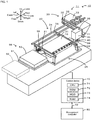
- Fig. 1 shows the overall configuration of component mounting system 10.
- Fig. 2 shows the overall configuration of mechanical chuck 40; fig. 2A shows the state before being mounted in head holding body 36; fig. 2B shows the state after being mounted in head holding body 36.
- Fig. 3 shows mechanical chuck 40 and tray 52.
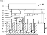
- Fig. 4 shows the positional relationship between mechanical chuck 40 and components P of tray 52.
- Tray 52 of figs. 4 and 5 shows cross section A-A of fig. 3 .
- left-right directions (X axis), front-rear directions (Y axis), and up-down directions (Z axis) are set as shown in figs. 1 to 3 .
- Mounting processing includes processing such as arranging a component above a board, mounting, insertion, joining, and gluing.
- Component mounting system 10 is provided with mounting device 11 that is connected to LAN 12 and configured as a mounting line, and management computer 80 that is connected to LAN 12 and manages information of components to be mounted and so on.
- Multiple mounting devices 11 that each perform mounting processing of mounting an electronic component (referred to as "component P") onto board 16 are arranged from an upstream side to a downstream side (left to right in fig. 1 ) in component mounting system 10. Note that fig. 1 only shows one mounting device 11.
- Mounting device 11 is provided with board conveyance unit 20 that conveys board 16, board supporting unit 25 that supports board 16 from below, and head moving unit 30 including head unit 35 that picks up component P by gripping it and moving above board 16. Further, component mounting device 11 is provided with supply unit 50 including tray 52 that houses components P, part camera 58 that images component P gripped by head unit 35 from below, side camera 38 that images component P gripped by head unit 35 from the side, and control device 70 that performs various controls.
- Board conveyance unit 20 conveys board 16 from left to right using conveyor belts 22 and 22 (only one of these is shown in fig. 1 ) that are respectively attached to a pair of front/rear supporting plates 21 and 21.
- Board supporting unit 25 is provided with a backup plate removably attached to a base plate, and multiple support pins provided on the backup plate that support board 16 from below. This board supporting unit 25 supports from below board 16 that is conveyed and fixed by board conveyance unit 20.
- Head moving unit 30 is provided with X-axis slider 31, guide rails 32, Y-axis slider 33, and guide rails 34, and the like.
- X-axis slider 31 is attached to the front surface of Y-axis slider 33, which is slidable in the front/rear direction, so as to be slidable in the left/right direction.
- Y-axis slider 33 is slidably attached to a pair of guide rails 34 that extend in the front/rear direction.
- Guide rails 32 that extend in the left/right direction are provided on the front surface of Y-axis slider 33, and X-axis slider 31 is attached to these guide rails 32 so as to be slidable in the left/right direction.
- Head unit 35 is attached to X-axis slider 31 and moves in a left/right direction with the left/right direction movement of X-axis slider 31 along guide rails 32 and 32, and moves in a front/rear direction with the front/rear movement of Y-axis slider 33 along guide rails 34 and 34. This allows head unit 35 to move in an XY plane.
- Sliders 31 and 33 are each driven by a servo motor that is not shown in the figures.
- Head unit 35 picks up components and moves above board 16, and is attached to the front surface of X-axis slider 31.
- Head unit 35 is provided with head holding body 36 arranged on X-axis slider 31, and mechanical chuck 40 held by head holding body 36 that picks up component P from tray 52 by gripping component P.
- As shown in fig. 2 provided on the lower surface of head holding body 36 are a pair of supporting moving sections 37 and 37 that are moved towards/away from each other in the front/rear direction by a drive section, which is not shown.
- a mounting section, which is not shown, is formed on the lower surface of supporting moving sections 37, and mechanical chuck 40 is held by joint 39 of mechanical chuck 40 being inserted into and fixed in these mounting sections ( fig. 2B ).
- Control device 70 obtains the deviation in the height direction (up/down direction) of picked up component P by analyzing the image captured by side camera 38.
- mechanical chuck 40 is provided with first holding member 41 and second holding member 42, and is configured as a holding tool that picks up component P by gripping an upper end of component P at a predetermined position.
- First holding member 41 is provided with base section 41a the upper surface on which joint 39 that connects to head holding body 36 is arranged, and support plate 41b formed in a direction straight down from base section 41a.
- first gripping member 43 on which gripping surface 44 that contacts component P is formed, is provided on the lower end of support plate 41b.
- Second holding member 42 is provided with base section 42a the upper surface on which joint 39 that connects to head holding body 36 is arranged, and second gripping member 47 formed in a direction straight down from base section 42a; gripping surface 48 that contacts component P is formed on the lower front surface of second gripping member 47.
- Mechanical chuck 40 picks up component P housed in tray 52 by gripping component P with contacting point 46 of cam follower 45 contacting tray 52 by first gripping member 43 of first holding member 41 and second gripping member 47 of second holding member 42 approaching each other.
- Mechanical chuck 40 is raised/lowered in the Z-axis direction (up/down direction), which is perpendicular to the X-axis and Y-axis directions, by a raising/lowering device that has a Z-axis motor, which is not shown, as a drive source. Also, mechanical chuck 40 is rotatable in the Z-axis direction by a rotation mechanism, which is not shown.
- mechanical chuck 40 When mechanical chuck 40 grips component P above tray 52, and when mechanical chuck 40 arranges component P on board 16, positioning is performed in the rotation direction at a predetermined position. For example, mechanical chuck 40, when gripping component P above tray 52, rotates and positions such that groove 54 and first and second gripping members 43 and 47 are parallel.
- Supply unit 50 is provided with a magazine cassette, which is not shown, that houses multiple trays 52 housing multiple components P, pallet 51 to which a desired tray 52 is fixed, and a tray moving section, which is not shown, that moves pallet 51 to which tray 52 is fixed between a predetermined initial position and a pickup position.
- Tray 52 is formed from plastic with a roughly rectangular external shape, and as shown in fig. 3 , housing cavities 53 for housing components P and grooves 54 that connect housing cavities 53 in the front/rear direction are formed in tray 52.
- Housing cavities 53 are multiple rectangular cuboid cavities arranged in the front/rear and left/right directions; grooves 54 are cavities for first gripping member 43 and second gripping member 47 to enter when mechanical chuck 40 grips component P.
- Tray 52 when being used for mounting processing, is fixed to pallet 51 with, for example, a metal fixture, a magnet, or the like.
- the pallet 51 is pulled forward from the magazine pallet, and when arranged at a predetermined position, components housed in tray 52 are able to be picked up by head unit 35.
- Component P includes a curved section curved at the lower of the component, and is a tall component.
- Component P for example, may be a component to be arranged on another component already arranged on board 16.
- the reference position which is the reference for that height position, and the height position itself are not particularly limited.
- the reference position is the surface on which component P is loaded
- height L1 can be used
- the reference position is the lower surface of supporting moving section 37
- height L2 can be used
- the reference position is the lower surface of head holding body 36
- height L3 can be used.
- cam follower 45 was described as an item that contacts upper surface 55 of tray 52; however, this is not limited to surface 55, so long as tray 52 is contacted and the relative positional relationship between component P and gripping region A is decided.
- Management computer 80 manages information of multiple mounting devices 11, and is provided with an HDD on which is memorized production condition information and so on used in the mounting processing of mounting device 11.
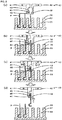
- control device 70 lowers mechanical chuck 40 such that contacting point 46 of cam follower 45 contacts upper surface 55 of tray 52 ( fig. 5B ). At this time, the predetermined position of component P is able to be gripped by first gripping member 43 and second gripping member 47.
- control device 70 moves the pair of supporting moving sections 37 (refer to fig. 2 ) towards each other other, contacts component P with gripping surface 44 of first gripping member 43 and gripping surface 48 of second gripping member 47 so as to grip component P ( fig. 5C ).
- control device 70 raises mechanical chuck 40 and obtains the deviation in the height direction of component P gripped by mechanical chuck 40 by imaging component P using side camera 38.
- control device 70 controls sliders 31 and 33 such that component P gripped by mechanical chuck 40 comes directly above a predetermined position on board 16, and arranges component P at a position after correcting for the gripping position deviation of component P.
- Tray 52 of the present embodiment corresponds to the housing section
- cam follower 45 corresponds to the contacting section
- first gripping member 43 and second gripping member 47 correspond to the gripping section
- first holding member 41 and second holding member 42 correspond to the holding member
- control device 70 corresponds to the control means
- head holding body 36 corresponds to the head holding body.
- Mounting device 11 described above is provided with mechanical chuck 40 that picks up component P housed in tray 52 by gripping component P in a state with cam follower 45 contacting tray 52 housing component P at a predetermined height.
- component P is positioned stably at a height based on the predetermined height. Accordingly, with mechanical chuck 40, component P is gripped at a gripping position which is more stable in the height direction.
- mechanical chuck 40 compared to an item that performs positioning of component P in the height direction by contacting component P with a member, effects on component P such as damage and deformation are curtailed. Further, in a state with first and second gripping members 43 and 47 gripping a component, compared to pickup using a suction nozzle for example, position deviation of components in the height direction may occur, meaning a there is a strong need to use the present invention.
- first gripping member 43 and second gripping member 47 are smooth, and it is easy to grip the component at a more stable gripping position in the height direction.
- cam follower 45 is provided on first holding member 41, it is possible to change mechanical chuck 40 based on the type of component, making it possible to grip various components at a more stable gripping position in the height direction.
- tray 52 is contacted at two locations by a pair of cam followers 45, it is possible to grip component P at a gripping position which is more stable in the height direction.
- cam follower 45 which is rotatable, is provided as the contacting section, but this is not limited to a rotatable item, so long as it contacts tray 52.
- Fig. 6 shows operation of mechanical chuck 40B, which is a different mechanical chuck; fig. 6A showing a state before gripping component P; fig. 6B shows a state with tray 52 contacted and component P gripped; and fig. 6C shows a state with component P picked up.
- Mechanical chuck 40B is provided with first holding member 41B and second holding member 42B, and is configured as a holding tool that picks up component P by gripping an upper end of component P at a predetermined position.
- control section 70 moves mechanical chuck 40 directly above component P ( fig. 6A ).
- control device 70 lowers mechanical chuck 40B such that contacting point 46B of contacting member 45B contacts upper surface 55 of tray 52, moves the pair of supporting moving sections 37 towards each other, such that component P is gripped by the gripping surface of first gripping claw 43B and the gripping surface of second gripping claw 47B contact component P ( fig. 6B ).
- control device 70 raises mechanical chuck 40B to pick up component P from housing cavity 53 of tray 52.
- component P is positioned stably at a height based on the predetermined height, and component P is gripped at a gripping position more stable in the height direction.
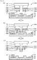
- cam follower 45 was described as the contacting section; however, for example, the mechanical chuck may be provided with cam follower 45 and contacting member 45B as a contacting section.
- cam follower 45 is provided on first holding member 41, and the contacting section is not provided on second holding member 42; however, cam follower 45 and contacting member 45B may be provided on second holding member 42 as well.
- cam follower 45 as a contacting section is made to contact tray 52; however, for example, the contacting section and tray 52 may be pushed against each other, or tray 52 may be pressed more strongly with the contacting section. This allows the position deviation in the height direction to be curtailed even more.
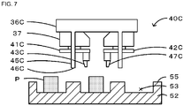
- Pillar-shaped contacting member 45C that contacts upper surface 55 of tray 52 housing components P at a predetermined height position is provided on head holding body 36C.
- Contacting point 46C that contacts upper surface 55 of tray 52 is the bottom surface of this contacting member 45C.
- mechanical chuck 40 is provided with two cam followers 45 as contacting sections such that tray 52 is contacted at two locations; however, the invention is not restricted to this, and the contacting section may contact tray 52 at one location, or the contacting section may contact tray 52 at three or more locations. Contacting tray 52 at two or more locations with the contacting section is desirable because this makes position deviation in the height direction less likely.
- mounting device 11 was described as an embodiment, but the invention is not restricted to this and may take the form of mechanical chuck 40.
- the present invention may be applied to the industrial field of electronic component mounting.
- 47C second gripping claw; 48: gripping surface; 50: supply unit; 51: pallet; 52: tray; 53: housing cavity; 54: groove; 55: upper surface; 58: part camera; 70: control device; 71: CPU; 72: ROM; 73: HDD; 74: RAM; 80: management computer; A: gripping region; P: component
Landscapes
- Engineering & Computer Science (AREA)
- Manufacturing & Machinery (AREA)
- Microelectronics & Electronic Packaging (AREA)
- Supply And Installment Of Electrical Components (AREA)
- Manipulator (AREA)
Claims (7)
- Montagevorrichtung (11) zum Durchführen von Montage-Verarbeitung zum Montieren eines Bauteils (P) an einer vorgegebenen Montageposition auf einer Platine (16), wobei die Montagevorrichtung (11) umfasst:eine Kopf-Einheit (35), die enthält:einen Teilabschnitt (45; 45B; 45C) zum Herstellen von Kontakt, mit dem mit einem Aufnahme-Teilabschnitt (52), der ein Bauteil (P) aufnimmt, an einer vorgegebenen Höhenposition Kontakt so hergestellt wird, dass die relative Positionsbeziehung zwischen dem Teilabschnitt (45; 45B; 45C) zum Herstellen von Kontakt und dem Bauteil (P) in der Höhenrichtung bestimmt wird, wenn der Teilabschnitt (45; 45B; 45C) zum Herstellen von Kontakt mit dem Aufnahme-Teilabschnitt (52) in Kontakt kommt, undeinen Greif-Teilabschnitt (43, 47; 43B, 47B; 43C, 47C) zum Entnehmen eines in dem Aufnahme-Teilabschnitt (52) aufgenommenen Bauteils (P) durch Greifen des Bauteils (P); sowieeine Steuerungseinrichtung (70), die so eingerichtet ist, dass sie den Greif-Teilabschnitt (43, 47; 43B, 47B; 47B; 43C, 47C) so bewegt, dass er das in dem Aufnahme-Teilabschnitt (52) aufgenommene Bauteil (P) in einem Zustand greift, in dem der Teilabschnitt (45; 45B; 45C) zum Herstellen von Kontakt mit dem Aufnahme-Teilabschnitt (52) in Kontakt kommt.
- Montagevorrichtung (11) nach Anspruch 1, wobei
der Teilabschnitt (45) zum Herstellen von Kontakt ein Eingriffsglied (45) einschließt, das sich, wenn sich der Greif-Teilabschnitt (43, 47) beim Entnehmen des Bauteils (P) bewegt, entsprechend der Bewegung des Greif-Teilabschnitts (43, 47) in einem Zustand dreht, in dem er mit dem Aufnahme-Teilabschnitt (52) in Kontakt ist. - Montagevorrichtung (11) nach Anspruch 1 oder 2, wobei
die Kopf-Einheit (35) enthält:ein Halte-Element (41, 42; 41B, 42B), an dem sich der Greif-Teilabschnitt (43, 47) befindet, sowieeinen Kopf-Haltekörper (36), an dem das Halte-Element (41, 42; 41B, 42B) angebracht ist,und wobeider Teilabschnitt (45; 45B) zum Herstellen von Kontakt sich an dem Halte-Element (41, 42; 41B, 42B) befindet. - Montagevorrichtung (11) nach einem der Ansprüche 1 bis 3, wobei die Kopf-Einheit (35) enthält:ein Halte-Element (41C, 42C), an dem sich der Greif-Teilabschnitt (43C, 47C) befindet, sowieeinen Kopf-Haltekörper (36C), an dem das Halte-Element (41C, 42C) angebracht ist,und wobei des Weiterender Teilabschnitt (45C) zum Herstellen von Kontakt sich an dem Kopf-Haltekörper (36C) befindet.
- Montagevorrichtung (11) nach einem der Ansprüche 1 bis 4, wobei
der Teilabschnitt (45; 45B; 45C) zum Herstellen von Kontakt so eingerichtet ist, dass er mit dem Aufnahme-Teilabschnitt (52) an wenigstens zwei Stellen in Kontakt kommen kann. - Montagevorrichtung (11) nach einem der Ansprüche 1 bis 5, wobei
die Kopf-Einheit (35) mit einem Höhen-Verstellmechanismus versehen ist, der Änderungen der Höhe des Teilabschnitts zum Herstellen von Kontakt in Bezug auf den Greif-Teilabschnitt zulässt. - Halte-Element (41, 42; 41B, 42B) zum Montieren an einer Kopf-Einheit (35) einer Montagevorrichtung (11), die Montage-Verarbeitung zum Montieren eines Bauteils an einer vorgegebenen Montageposition auf einer Platine (16) durchführt, wobei das Halte-Element (41, 42; 41B, 42B) umfasst:einen Teilabschnitt (45; 45B) zum Herstellen von Kontakt, mit dem Kontakt mit einem Aufnahme-Teilabschnitt (52) hergestellt wird, der ein Bauteil (P) aufnimmt, sowieeinen Greif-Teilabschnitt (43, 47; 43B, 47B), mit dem ein in dem Gehäuseabschnitt (52) aufgenommenes Bauteil (P) entnommen wird, indem er zum Greifen des Bauteils (P) bewegt wird, während der Teilabschnitt zum Herstellen von Kontakt und der Gehäuse-Teilabschnitt (52) miteinander in Kontakt sind.
Applications Claiming Priority (1)
| Application Number | Priority Date | Filing Date | Title |
|---|---|---|---|
| PCT/JP2014/050828 WO2015107680A1 (ja) | 2014-01-17 | 2014-01-17 | 実装装置及び保持部材 |
Publications (3)
| Publication Number | Publication Date |
|---|---|
| EP3096595A1 EP3096595A1 (de) | 2016-11-23 |
| EP3096595A4 EP3096595A4 (de) | 2016-12-14 |
| EP3096595B1 true EP3096595B1 (de) | 2019-08-07 |
Family
ID=53542598
Family Applications (1)
| Application Number | Title | Priority Date | Filing Date |
|---|---|---|---|
| EP14879128.8A Active EP3096595B1 (de) | 2014-01-17 | 2014-01-17 | Montagevorrichtung und halteelement |
Country Status (5)
| Country | Link |
|---|---|
| US (1) | US10617049B2 (de) |
| EP (1) | EP3096595B1 (de) |
| JP (1) | JP6204996B2 (de) |
| CN (1) | CN105900541B (de) |
| WO (1) | WO2015107680A1 (de) |
Families Citing this family (2)
| Publication number | Priority date | Publication date | Assignee | Title |
|---|---|---|---|---|
| WO2015107680A1 (ja) * | 2014-01-17 | 2015-07-23 | 富士機械製造株式会社 | 実装装置及び保持部材 |
| JP6858142B2 (ja) * | 2018-01-22 | 2021-04-14 | 川崎重工業株式会社 | ロボットハンド |
Family Cites Families (19)
| Publication number | Priority date | Publication date | Assignee | Title |
|---|---|---|---|---|
| JPS63236400A (ja) * | 1987-03-13 | 1988-10-03 | エヌ・ベー・フィリップス・フルーイランペンファブリケン | 把持装置 |
| JPH0691355B2 (ja) * | 1988-01-19 | 1994-11-14 | 三洋電機株式会社 | 電子部品位置決め装置 |
| US5509193A (en) * | 1994-05-06 | 1996-04-23 | Micron Technology, Inc. | Apparatus for loading and unloading burn-in boards |
| JP2930565B2 (ja) * | 1996-10-05 | 1999-08-03 | 三星電子株式会社 | サーボモータを用いた半導体チップパッケージのローディング及びアンローディング装置 |
| JP4546663B2 (ja) * | 2001-04-23 | 2010-09-15 | 富士機械製造株式会社 | プリント板保持装置および電気部品装着システム |
| JP2003031992A (ja) * | 2001-07-17 | 2003-01-31 | Fuji Mach Mfg Co Ltd | 電気部品載置方法および電気部品載置装置 |
| JP4541601B2 (ja) | 2001-07-19 | 2010-09-08 | 富士機械製造株式会社 | 電動チャックを用いた電気部品装着システム |
| WO2003059033A1 (en) * | 2001-12-28 | 2003-07-17 | Matsushita Electric Industrial Co., Ltd. | Mounting device |
| CN101141872B (zh) * | 2002-12-02 | 2010-12-01 | 松下电器产业株式会社 | 安装头部的移动方法 |
| WO2004059332A1 (en) * | 2002-12-25 | 2004-07-15 | Ricoh Company, Ltd. | An ic transfer device |
| US20040183320A1 (en) * | 2003-03-19 | 2004-09-23 | Brian Evans | Bi-directional gripping of rectangular devices/components |
| JP2004319739A (ja) * | 2003-04-16 | 2004-11-11 | Fuji Electric Holdings Co Ltd | 電子部品挿入装置の電子部品挿入方法 |
| JP2005108959A (ja) * | 2003-09-29 | 2005-04-21 | Hitachi High-Tech Instruments Co Ltd | 電子部品装着装置 |
| JP4516354B2 (ja) * | 2004-05-17 | 2010-08-04 | パナソニック株式会社 | 部品供給方法 |
| JP2006269793A (ja) * | 2005-03-24 | 2006-10-05 | Yamagata Casio Co Ltd | 電子部品のクランプヘッド及び部品実装装置 |
| US7337534B2 (en) * | 2005-04-07 | 2008-03-04 | Chi Ming Wong | SMD chip handling apparatus |
| JP4726241B2 (ja) * | 2007-02-16 | 2011-07-20 | シュンク・ジャパン株式会社 | 産業用ロボットのロボットハンド |
| JP5516307B2 (ja) * | 2010-10-12 | 2014-06-11 | 富士通株式会社 | 部品実装装置及び部品実装方法 |
| WO2015107680A1 (ja) * | 2014-01-17 | 2015-07-23 | 富士機械製造株式会社 | 実装装置及び保持部材 |
-
2014
- 2014-01-17 WO PCT/JP2014/050828 patent/WO2015107680A1/ja not_active Ceased
- 2014-01-17 JP JP2015557658A patent/JP6204996B2/ja active Active
- 2014-01-17 US US15/110,639 patent/US10617049B2/en active Active
- 2014-01-17 EP EP14879128.8A patent/EP3096595B1/de active Active
- 2014-01-17 CN CN201480072946.7A patent/CN105900541B/zh active Active
Non-Patent Citations (1)
| Title |
|---|
| None * |
Also Published As
| Publication number | Publication date |
|---|---|
| CN105900541B (zh) | 2019-07-09 |
| JPWO2015107680A1 (ja) | 2017-03-23 |
| JP6204996B2 (ja) | 2017-09-27 |
| US10617049B2 (en) | 2020-04-07 |
| EP3096595A4 (de) | 2016-12-14 |
| CN105900541A (zh) | 2016-08-24 |
| EP3096595A1 (de) | 2016-11-23 |
| US20160330881A1 (en) | 2016-11-10 |
| WO2015107680A1 (ja) | 2015-07-23 |
Similar Documents
| Publication | Publication Date | Title |
|---|---|---|
| EP3367774B1 (de) | System zur durchführung von arbeit auf einem substrat und einführverfahren | |
| JP2016219474A (ja) | 部品取出し装置および部品取出し方法ならびに部品実装装置 | |
| WO2016129069A1 (ja) | 部品供給装置 | |
| CN103517627A (zh) | 元件安装装置、元件供料器及其拉拔限制解除方法 | |
| JP2016219472A (ja) | 部品取出し装置および部品取出し方法ならびに部品実装装置 | |
| EP3096595B1 (de) | Montagevorrichtung und halteelement | |
| CN105407700A (zh) | 插入头、元件插入装置及元件安装线 | |
| EP3310146B1 (de) | Arbeitsmaschine für substrate und erkennungsverfahren | |
| JP6009695B2 (ja) | 部品実装装置、部品実装方法 | |
| EP3125664B1 (de) | Komponentenmontagevorrichtung | |
| EP3595424B1 (de) | Dreidimensionale montagevorrichtung und dreidimensionales montageverfahren | |
| EP3595423B1 (de) | Fördervorrichtung und montage-assoziierte vorrichtung | |
| JP7664936B2 (ja) | 表示装置、および干渉確認方法 | |
| US11134594B2 (en) | Component supply system and component mounting machine | |
| CN105229872A (zh) | 端子插入装置和端子插入方法 | |
| EP3397041B1 (de) | Informationsverarbeitungsvorrichtung, montagevorrichtung, informationsverarbeitungsverfahren und komponentenhaltewerkzeug | |
| EP3550950B1 (de) | Betriebsmaschine | |
| JP6554389B2 (ja) | 対基板作業システム | |
| EP3379911B1 (de) | Arbeitsmaschine für substrate und einsetzverfahren | |
| EP3021651A1 (de) | Verfahren zur montage von bauelementen auf einem substrat in einer bauelement-montagevorrichtung und bauelement-montagevorrichtung | |
| JP2016219473A (ja) | 部品取出し装置および部品取出し方法ならびに部品実装装置 | |
| EP3089572B1 (de) | Substratarbeitsvorrichtung | |
| EP3500081A1 (de) | Substratbearbeitungsmaschine | |
| JP2011023684A (ja) | 電子部品実装装置 | |
| JPWO2019097584A1 (ja) | 作業機、装着方法 |
Legal Events
| Date | Code | Title | Description |
|---|---|---|---|
| PUAI | Public reference made under article 153(3) epc to a published international application that has entered the european phase |
Free format text: ORIGINAL CODE: 0009012 |
|
| 17P | Request for examination filed |
Effective date: 20160704 |
|
| AK | Designated contracting states |
Kind code of ref document: A1 Designated state(s): AL AT BE BG CH CY CZ DE DK EE ES FI FR GB GR HR HU IE IS IT LI LT LU LV MC MK MT NL NO PL PT RO RS SE SI SK SM TR |
|
| AX | Request for extension of the european patent |
Extension state: BA ME |
|
| A4 | Supplementary search report drawn up and despatched |
Effective date: 20161111 |
|
| RIC1 | Information provided on ipc code assigned before grant |
Ipc: H05K 13/04 20060101AFI20161107BHEP |
|
| DAX | Request for extension of the european patent (deleted) | ||
| STAA | Information on the status of an ep patent application or granted ep patent |
Free format text: STATUS: EXAMINATION IS IN PROGRESS |
|
| 17Q | First examination report despatched |
Effective date: 20180511 |
|
| RAP1 | Party data changed (applicant data changed or rights of an application transferred) |
Owner name: FUJI CORPORATION |
|
| RIN1 | Information on inventor provided before grant (corrected) |
Inventor name: TSUCHIYA, YUSUKE Inventor name: YOKOI, YUTA |
|
| GRAP | Despatch of communication of intention to grant a patent |
Free format text: ORIGINAL CODE: EPIDOSNIGR1 |
|
| STAA | Information on the status of an ep patent application or granted ep patent |
Free format text: STATUS: GRANT OF PATENT IS INTENDED |
|
| INTG | Intention to grant announced |
Effective date: 20190415 |
|
| GRAS | Grant fee paid |
Free format text: ORIGINAL CODE: EPIDOSNIGR3 |
|
| GRAA | (expected) grant |
Free format text: ORIGINAL CODE: 0009210 |
|
| STAA | Information on the status of an ep patent application or granted ep patent |
Free format text: STATUS: THE PATENT HAS BEEN GRANTED |
|
| AK | Designated contracting states |
Kind code of ref document: B1 Designated state(s): AL AT BE BG CH CY CZ DE DK EE ES FI FR GB GR HR HU IE IS IT LI LT LU LV MC MK MT NL NO PL PT RO RS SE SI SK SM TR |
|
| REG | Reference to a national code |
Ref country code: GB Ref legal event code: FG4D |
|
| REG | Reference to a national code |
Ref country code: CH Ref legal event code: EP Ref country code: AT Ref legal event code: REF Ref document number: 1165895 Country of ref document: AT Kind code of ref document: T Effective date: 20190815 |
|
| REG | Reference to a national code |
Ref country code: DE Ref legal event code: R096 Ref document number: 602014051553 Country of ref document: DE |
|
| REG | Reference to a national code |
Ref country code: IE Ref legal event code: FG4D |
|
| REG | Reference to a national code |
Ref country code: NL Ref legal event code: MP Effective date: 20190807 |
|
| REG | Reference to a national code |
Ref country code: LT Ref legal event code: MG4D |
|
| PG25 | Lapsed in a contracting state [announced via postgrant information from national office to epo] |
Ref country code: FI Free format text: LAPSE BECAUSE OF FAILURE TO SUBMIT A TRANSLATION OF THE DESCRIPTION OR TO PAY THE FEE WITHIN THE PRESCRIBED TIME-LIMIT Effective date: 20190807 Ref country code: PT Free format text: LAPSE BECAUSE OF FAILURE TO SUBMIT A TRANSLATION OF THE DESCRIPTION OR TO PAY THE FEE WITHIN THE PRESCRIBED TIME-LIMIT Effective date: 20191209 Ref country code: SE Free format text: LAPSE BECAUSE OF FAILURE TO SUBMIT A TRANSLATION OF THE DESCRIPTION OR TO PAY THE FEE WITHIN THE PRESCRIBED TIME-LIMIT Effective date: 20190807 Ref country code: HR Free format text: LAPSE BECAUSE OF FAILURE TO SUBMIT A TRANSLATION OF THE DESCRIPTION OR TO PAY THE FEE WITHIN THE PRESCRIBED TIME-LIMIT Effective date: 20190807 Ref country code: NL Free format text: LAPSE BECAUSE OF FAILURE TO SUBMIT A TRANSLATION OF THE DESCRIPTION OR TO PAY THE FEE WITHIN THE PRESCRIBED TIME-LIMIT Effective date: 20190807 Ref country code: LT Free format text: LAPSE BECAUSE OF FAILURE TO SUBMIT A TRANSLATION OF THE DESCRIPTION OR TO PAY THE FEE WITHIN THE PRESCRIBED TIME-LIMIT Effective date: 20190807 Ref country code: NO Free format text: LAPSE BECAUSE OF FAILURE TO SUBMIT A TRANSLATION OF THE DESCRIPTION OR TO PAY THE FEE WITHIN THE PRESCRIBED TIME-LIMIT Effective date: 20191107 Ref country code: BG Free format text: LAPSE BECAUSE OF FAILURE TO SUBMIT A TRANSLATION OF THE DESCRIPTION OR TO PAY THE FEE WITHIN THE PRESCRIBED TIME-LIMIT Effective date: 20191107 |
|
| REG | Reference to a national code |
Ref country code: AT Ref legal event code: MK05 Ref document number: 1165895 Country of ref document: AT Kind code of ref document: T Effective date: 20190807 |
|
| PG25 | Lapsed in a contracting state [announced via postgrant information from national office to epo] |
Ref country code: AL Free format text: LAPSE BECAUSE OF FAILURE TO SUBMIT A TRANSLATION OF THE DESCRIPTION OR TO PAY THE FEE WITHIN THE PRESCRIBED TIME-LIMIT Effective date: 20190807 Ref country code: ES Free format text: LAPSE BECAUSE OF FAILURE TO SUBMIT A TRANSLATION OF THE DESCRIPTION OR TO PAY THE FEE WITHIN THE PRESCRIBED TIME-LIMIT Effective date: 20190807 Ref country code: RS Free format text: LAPSE BECAUSE OF FAILURE TO SUBMIT A TRANSLATION OF THE DESCRIPTION OR TO PAY THE FEE WITHIN THE PRESCRIBED TIME-LIMIT Effective date: 20190807 Ref country code: LV Free format text: LAPSE BECAUSE OF FAILURE TO SUBMIT A TRANSLATION OF THE DESCRIPTION OR TO PAY THE FEE WITHIN THE PRESCRIBED TIME-LIMIT Effective date: 20190807 Ref country code: GR Free format text: LAPSE BECAUSE OF FAILURE TO SUBMIT A TRANSLATION OF THE DESCRIPTION OR TO PAY THE FEE WITHIN THE PRESCRIBED TIME-LIMIT Effective date: 20191108 Ref country code: IS Free format text: LAPSE BECAUSE OF FAILURE TO SUBMIT A TRANSLATION OF THE DESCRIPTION OR TO PAY THE FEE WITHIN THE PRESCRIBED TIME-LIMIT Effective date: 20191207 |
|
| PG25 | Lapsed in a contracting state [announced via postgrant information from national office to epo] |
Ref country code: TR Free format text: LAPSE BECAUSE OF FAILURE TO SUBMIT A TRANSLATION OF THE DESCRIPTION OR TO PAY THE FEE WITHIN THE PRESCRIBED TIME-LIMIT Effective date: 20190807 |
|
| PG25 | Lapsed in a contracting state [announced via postgrant information from national office to epo] |
Ref country code: RO Free format text: LAPSE BECAUSE OF FAILURE TO SUBMIT A TRANSLATION OF THE DESCRIPTION OR TO PAY THE FEE WITHIN THE PRESCRIBED TIME-LIMIT Effective date: 20190807 Ref country code: IT Free format text: LAPSE BECAUSE OF FAILURE TO SUBMIT A TRANSLATION OF THE DESCRIPTION OR TO PAY THE FEE WITHIN THE PRESCRIBED TIME-LIMIT Effective date: 20190807 Ref country code: PL Free format text: LAPSE BECAUSE OF FAILURE TO SUBMIT A TRANSLATION OF THE DESCRIPTION OR TO PAY THE FEE WITHIN THE PRESCRIBED TIME-LIMIT Effective date: 20190807 Ref country code: AT Free format text: LAPSE BECAUSE OF FAILURE TO SUBMIT A TRANSLATION OF THE DESCRIPTION OR TO PAY THE FEE WITHIN THE PRESCRIBED TIME-LIMIT Effective date: 20190807 Ref country code: EE Free format text: LAPSE BECAUSE OF FAILURE TO SUBMIT A TRANSLATION OF THE DESCRIPTION OR TO PAY THE FEE WITHIN THE PRESCRIBED TIME-LIMIT Effective date: 20190807 Ref country code: DK Free format text: LAPSE BECAUSE OF FAILURE TO SUBMIT A TRANSLATION OF THE DESCRIPTION OR TO PAY THE FEE WITHIN THE PRESCRIBED TIME-LIMIT Effective date: 20190807 |
|
| PG25 | Lapsed in a contracting state [announced via postgrant information from national office to epo] |
Ref country code: CZ Free format text: LAPSE BECAUSE OF FAILURE TO SUBMIT A TRANSLATION OF THE DESCRIPTION OR TO PAY THE FEE WITHIN THE PRESCRIBED TIME-LIMIT Effective date: 20190807 Ref country code: SK Free format text: LAPSE BECAUSE OF FAILURE TO SUBMIT A TRANSLATION OF THE DESCRIPTION OR TO PAY THE FEE WITHIN THE PRESCRIBED TIME-LIMIT Effective date: 20190807 Ref country code: SM Free format text: LAPSE BECAUSE OF FAILURE TO SUBMIT A TRANSLATION OF THE DESCRIPTION OR TO PAY THE FEE WITHIN THE PRESCRIBED TIME-LIMIT Effective date: 20190807 Ref country code: IS Free format text: LAPSE BECAUSE OF FAILURE TO SUBMIT A TRANSLATION OF THE DESCRIPTION OR TO PAY THE FEE WITHIN THE PRESCRIBED TIME-LIMIT Effective date: 20200224 |
|
| REG | Reference to a national code |
Ref country code: DE Ref legal event code: R097 Ref document number: 602014051553 Country of ref document: DE |
|
| PLBE | No opposition filed within time limit |
Free format text: ORIGINAL CODE: 0009261 |
|
| STAA | Information on the status of an ep patent application or granted ep patent |
Free format text: STATUS: NO OPPOSITION FILED WITHIN TIME LIMIT |
|
| PG2D | Information on lapse in contracting state deleted |
Ref country code: IS |
|
| 26N | No opposition filed |
Effective date: 20200603 |
|
| PG25 | Lapsed in a contracting state [announced via postgrant information from national office to epo] |
Ref country code: MC Free format text: LAPSE BECAUSE OF FAILURE TO SUBMIT A TRANSLATION OF THE DESCRIPTION OR TO PAY THE FEE WITHIN THE PRESCRIBED TIME-LIMIT Effective date: 20190807 Ref country code: SI Free format text: LAPSE BECAUSE OF FAILURE TO SUBMIT A TRANSLATION OF THE DESCRIPTION OR TO PAY THE FEE WITHIN THE PRESCRIBED TIME-LIMIT Effective date: 20190807 |
|
| REG | Reference to a national code |
Ref country code: CH Ref legal event code: PL |
|
| GBPC | Gb: european patent ceased through non-payment of renewal fee |
Effective date: 20200117 |
|
| REG | Reference to a national code |
Ref country code: BE Ref legal event code: MM Effective date: 20200131 |
|
| PG25 | Lapsed in a contracting state [announced via postgrant information from national office to epo] |
Ref country code: LU Free format text: LAPSE BECAUSE OF NON-PAYMENT OF DUE FEES Effective date: 20200117 Ref country code: GB Free format text: LAPSE BECAUSE OF NON-PAYMENT OF DUE FEES Effective date: 20200117 Ref country code: FR Free format text: LAPSE BECAUSE OF NON-PAYMENT OF DUE FEES Effective date: 20200131 |
|
| PG25 | Lapsed in a contracting state [announced via postgrant information from national office to epo] |
Ref country code: BE Free format text: LAPSE BECAUSE OF NON-PAYMENT OF DUE FEES Effective date: 20200131 Ref country code: LI Free format text: LAPSE BECAUSE OF NON-PAYMENT OF DUE FEES Effective date: 20200131 Ref country code: CH Free format text: LAPSE BECAUSE OF NON-PAYMENT OF DUE FEES Effective date: 20200131 |
|
| PG25 | Lapsed in a contracting state [announced via postgrant information from national office to epo] |
Ref country code: IE Free format text: LAPSE BECAUSE OF NON-PAYMENT OF DUE FEES Effective date: 20200117 |
|
| PG25 | Lapsed in a contracting state [announced via postgrant information from national office to epo] |
Ref country code: MT Free format text: LAPSE BECAUSE OF FAILURE TO SUBMIT A TRANSLATION OF THE DESCRIPTION OR TO PAY THE FEE WITHIN THE PRESCRIBED TIME-LIMIT Effective date: 20190807 Ref country code: CY Free format text: LAPSE BECAUSE OF FAILURE TO SUBMIT A TRANSLATION OF THE DESCRIPTION OR TO PAY THE FEE WITHIN THE PRESCRIBED TIME-LIMIT Effective date: 20190807 |
|
| PG25 | Lapsed in a contracting state [announced via postgrant information from national office to epo] |
Ref country code: MK Free format text: LAPSE BECAUSE OF FAILURE TO SUBMIT A TRANSLATION OF THE DESCRIPTION OR TO PAY THE FEE WITHIN THE PRESCRIBED TIME-LIMIT Effective date: 20190807 |
|
| P01 | Opt-out of the competence of the unified patent court (upc) registered |
Effective date: 20230328 |
|
| PGFP | Annual fee paid to national office [announced via postgrant information from national office to epo] |
Ref country code: DE Payment date: 20241203 Year of fee payment: 12 |