WO2015107680A1 - 実装装置及び保持部材 - Google Patents
実装装置及び保持部材 Download PDFInfo
- Publication number
- WO2015107680A1 WO2015107680A1 PCT/JP2014/050828 JP2014050828W WO2015107680A1 WO 2015107680 A1 WO2015107680 A1 WO 2015107680A1 JP 2014050828 W JP2014050828 W JP 2014050828W WO 2015107680 A1 WO2015107680 A1 WO 2015107680A1
- Authority
- WO
- WIPO (PCT)
- Prior art keywords
- component
- holding member
- gripping
- contact
- mounting
- Prior art date
Links
Images


Classifications
-
- H—ELECTRICITY
- H05—ELECTRIC TECHNIQUES NOT OTHERWISE PROVIDED FOR
- H05K—PRINTED CIRCUITS; CASINGS OR CONSTRUCTIONAL DETAILS OF ELECTRIC APPARATUS; MANUFACTURE OF ASSEMBLAGES OF ELECTRICAL COMPONENTS
- H05K13/00—Apparatus or processes specially adapted for manufacturing or adjusting assemblages of electric components
- H05K13/04—Mounting of components, e.g. of leadless components
- H05K13/0404—Pick-and-place heads or apparatus, e.g. with jaws
- H05K13/0408—Incorporating a pick-up tool
-
- H—ELECTRICITY
- H05—ELECTRIC TECHNIQUES NOT OTHERWISE PROVIDED FOR
- H05K—PRINTED CIRCUITS; CASINGS OR CONSTRUCTIONAL DETAILS OF ELECTRIC APPARATUS; MANUFACTURE OF ASSEMBLAGES OF ELECTRICAL COMPONENTS
- H05K13/00—Apparatus or processes specially adapted for manufacturing or adjusting assemblages of electric components
- H05K13/04—Mounting of components, e.g. of leadless components
- H05K13/0404—Pick-and-place heads or apparatus, e.g. with jaws
Definitions
- the present invention relates to a mounting apparatus and a holding member.
- a mounting device at least a pair of movable members (holding claws) that can approach and separate from each other are provided, and the holding claws are moved by a position command exceeding the actual holding position so that the holding claws abut on the electronic component.
- the holding claw is stopped when an appropriate grasping force is obtained, the position is set as a new target, and the target position is controlled to be maintained by the holding claw (for example, Patent Documents). 1).
- the gripping force can be made constant and the electronic component can be stably held.
- a mechanical chuck that grips the component with a gripping claw may be used.
- a problem may occur in the placement of the component at the mounting position.
- the gripped component is photographed and it is determined whether the picked state of the component is appropriate, if the gripped component varies in the height direction, the determination of the picked state becomes inaccurate. There was a thing.
- the component may be deformed or damaged. As described above, there is a case where it is desired to appropriately adjust the sampling position of the parts in the height direction.
- the present invention has been made to solve such a problem, and has as its main object to provide a mounting apparatus and a holding member that can grip a component at a more stable gripping position in the height direction.
- the mounting apparatus of the present invention is A mounting apparatus that executes a mounting process for mounting a component at a predetermined mounting position on a board, A gripping member grips the component housed in the housing portion with the contact portion contacting the housing portion containing the component at a predetermined height position, and the contact portion and the housing portion being in contact with each other. And a head unit having a gripping part to be collected.
- sampling is performed by gripping the component housed in the housing portion in a state where the contact portion and the housing portion that houses the component are in contact at a predetermined height position.
- the component since the contact portion and the accommodating portion are in contact with each other, the component is stably positioned at a height corresponding to a predetermined height. Therefore, the component can be gripped at a more stable gripping position in the height direction. Further, it is possible to further suppress adverse effects on the component, such as deformation and breakage of the component, as compared with the component in which the member is brought into contact with the component and the height of the component is positioned.
- the position of the component may be displaced in the height direction as compared with the case where the component is sucked by the nozzle, for example, and the significance of adopting the present invention is high.
- the part accommodated in the accommodating part may be collected in a state where the abutting part and the accommodating part are pressed, or the accommodating part is pressed by the abutting part.
- the parts housed in the housing part may be collected.
- the “predetermined height position” may be any position as long as it determines the relative positional relationship between the gripping part and the component in the height direction.
- the abutting portion may have a cam follower that rotates in accordance with the movement in a state where the abutting portion is in contact with the accommodating portion when the gripping portion is moved when the component is collected. If it carries out like this, a movement of a holding part can be made smooth in the state which contact
- the head unit includes a holding member on which the grip portion is disposed and a head holding body on which the holding member is mounted, and the contact portion includes the holding member. It is good also as what is arrange
- the head unit includes a holding member on which the grip portion is disposed, and a head holding body on which the holding member is mounted, and the contact portion includes the head holding member. It may be disposed on the body.
- the contact portion may be in contact with the housing portion at two or more locations.
- the head unit may include a height adjusting mechanism capable of changing the predetermined height position of the contact portion.
- a height adjusting mechanism capable of changing the predetermined height position of the contact portion.
- the mounting apparatus of the present invention may include a control unit that moves the gripping part so as to grip a component housed in the housing part in a state where the contact part is in contact with the housing part. Good.
- a holding member is a holding member that is mounted on a head unit of a mounting apparatus that executes a mounting process for mounting a component at a predetermined mounting position on a substrate, and has a predetermined height in a storage portion that stores the component. It is good also as what has a contact part which contacts in a position, and a grasping part which grasps and collects parts stored in the storage part in the state where the contact part and the storage part contacted. Since this holding member is in a state in which the abutting portion and the accommodating portion are in contact with each other as in the mounting device described above, the component is stably positioned at a height corresponding to a predetermined height. The component can be gripped at a more stable gripping position in the height direction. In addition, in this holding member, various aspects of the mounting apparatus described above may be adopted, and a configuration that realizes each function of the mounting apparatus described above may be added.
- FIG. 2 is an explanatory diagram showing an outline of a configuration of a component mounting system 10.
- FIG. FIG. 3 is an explanatory diagram showing an outline of a configuration of a mechanical chuck 40. Explanatory drawing of the mechanical chuck 40 and the tray 52. FIG. Explanatory drawing of the positional relationship of the mechanical chuck 40 and the components P of the tray 52. FIG. Explanatory drawing of operation
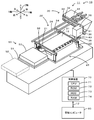
- FIG. 1 is an explanatory diagram showing an outline of the configuration of the component mounting system 10.
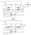
- 2A and 2B are explanatory views showing an outline of the configuration of the mechanical chuck 40.
- FIG. 2A is a diagram before mounting on the head holding body 36, and FIG. is there.
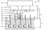
- FIG. 3 is an explanatory diagram of the mechanical chuck 40 and the tray 52.
- FIG. 4 is an explanatory diagram of the positional relationship between the mechanical chuck 40 and the component P of the tray 52. Note that the tray 52 in FIGS. 4 and 5 shows the AA cross section in FIG.
- the mounting process includes a process of placing, mounting, inserting, joining, and bonding components on a substrate.
- the component mounting system 10 includes a mounting device 11 connected to the LAN 12 and configured as a mounting line, and a management computer 80 connected to the LAN 12 and managing information on components to be mounted.
- a plurality of mounting apparatuses 11 that respectively perform a mounting process for mounting an electronic component (hereinafter referred to as “component P”) on a substrate 16 are arranged from upstream to downstream (from left to right in FIG. 1). . In FIG. 1, only one mounting apparatus 11 is shown.
- the mounting apparatus 11 includes a substrate transport unit 20 that transports the substrate 16, a substrate support unit 25 that supports the substrate 16 from the lower surface side, and a head unit 35 that picks up and moves the component P onto the substrate 16. And a head moving unit 30. Further, the mounting apparatus 11 includes a supply unit 50 having a tray 52 that accommodates the component P, a parts camera 58 that images the component P gripped by the head unit 35 from below, and a component P gripped by the head unit 35. A side camera 38 that captures images from the side and a control device 70 that executes various controls are provided.
- the substrate transport unit 20 transports the substrate 16 from left to right by conveyor belts 22 and 22 (only one of which is shown in FIG. 1) attached to a pair of front and rear support plates 21 and 21, respectively.
- the substrate support unit 25 includes a backup plate that is detachably attached to the base plate, and a plurality of support pins that are provided on the backup plate and support the substrate 16 from below.
- the substrate support unit 25 supports the substrate 16 from the back side of the substrate 16 that is transported and fixed by the substrate transport unit 20.
- the head moving unit 30 includes an X-axis slider 31, a guide rail 32, a Y-axis slider 33, a guide rail 34, and the like.
- the X-axis slider 31 is attached to the front surface of the Y-axis slider 33 that can slide in the front-rear direction so as to be slidable in the left-right direction.
- the Y-axis slider 33 is slidably attached to a pair of left and right guide rails 34 extending in the front-rear direction.
- a guide rail 32 extending in the left-right direction is provided on the front surface of the Y-axis slider 33, and the X-axis slider 31 is attached to the guide rail 32 so as to be slidable in the left-right direction.
- the head unit 35 is attached to the X-axis slider 31, moves in the left-right direction as the X-axis slider 31 moves in the left-right direction along the guide rail 32, and the Y-axis slider 33 moves to the guide rail 34. It moves in the front-rear direction as it moves in the front-rear direction along. Thus, the head unit 35 is movable on the XY plane.
- Each slider 31, 33 is driven by a servo motor (not shown).
- the head unit 35 attracts components and moves them onto the substrate 16, and is attached to the front surface of the X-axis slider 31.
- the head unit 35 includes a head holder 36 disposed on the X-axis slider 31, and a mechanical chuck 40 that holds the component P and is collected from the tray 52 held by the head holder 36.
- a pair of support moving portions 37, 37 are disposed on the lower surface of the head holder 36 so as to approach and separate in the front-rear direction by a drive source (not shown).
- a mounting portion (not shown) is formed on the lower surface side of the support moving portion 37, and the mechanical chuck 40 is held by inserting and fixing the joint 39 of the mechanical chuck 40 to the mounting portion (FIG. 2B).
- a side camera 38 that captures an image of the part P gripped by the mechanical chuck 40 from the side is fixed to the head unit 35 (see FIG. 1).
- the control device 70 can grasp the deviation in the height direction (vertical direction) of the collected component P by analyzing the image captured by the side camera 38.
- the mechanical chuck 40 includes a first holding member 41 and a second holding member 42, and holds the predetermined position on the upper end side of the component P to collect the component P. It is configured as.
- the first holding member 41 includes a base portion 41a in which a joint 39 connected to the head holding body 36 is disposed on the upper surface, and a support plate 41b formed vertically downward from the base portion 41a.
- the mechanical chuck 40 is provided with a first gripping member 43 having a gripping surface 44 in contact with the component P at the lower end of the support plate 41b.
- the first holding member 41 is formed with a pair of cam followers 45 that are in contact with the upper surface 55 of the tray 52 that accommodates the component P at a predetermined height position on both sides of the first gripping member 43 (FIG. 3). reference).
- the cam follower 45 is a roller that can rotate about its axis. When the first holding member 41 moves when the component P is collected from the tray 52, the cam follower 45 rotates with this movement while being in contact with the tray 52.
- a contact portion 46 that contacts the upper surface 55 of the tray 52 is the lower surface of the cam follower 45.
- the second holding member 42 includes a base portion 42a in which a joint 39 connected to the head holding body 36 is disposed on the upper surface, and a second gripping member 47 formed vertically downward from the base portion 42a.
- a gripping surface 48 in contact with the component P is formed on the lower front surface of the gripping member 47.
- the mechanical chuck 40 abuts the contact portion 46 of the cam follower 45 and the tray 52 by bringing the first gripping member 43 of the first holding member 41 close to the second gripping member 47 of the second holding member 42. In this state, the component P accommodated in the tray 52 is grasped and collected.
- the mechanical chuck 40 is lifted and lowered in the Z-axis direction (vertical direction) perpendicular to the X-axis and Y-axis directions by a lifting device using a Z-axis motor (not shown) as a drive source.
- the mechanical chuck 40 can be rotated in the Z-axis direction by a rotation mechanism (not shown).
- the mechanical chuck 40 is positioned in the rotational direction at a predetermined position when gripping the component P on the tray 52 or when placing the component P on the substrate 16. For example, when gripping the component P on the tray 52, the mechanical chuck 40 is rotated and positioned so that the longitudinal groove 54 and the first and second gripping members 43 and 47 are parallel to each other.
- the supply unit 50 includes a magazine cassette (not shown) that contains a plurality of trays 52 that contain a plurality of components P, a pallet 51 that fixes a desired tray 52, and a pallet 51 that fixes the tray 52 at a predetermined initial position and sampling position. And a tray moving unit (not shown) that moves between the two.
- the outer shape of the tray 52 is formed in a substantially rectangular parallelepiped using resin, and as shown in FIG. 3, an accommodation space 53 that accommodates the component P and a vertical groove 54 that connects the accommodation space 53 in the front-rear direction are formed. .
- the accommodating space 53 is a large number of rectangular parallelepiped spaces arranged in the front, rear, left, and right directions, and the vertical groove 54 is a space into which the first gripping member 43 and the second gripping member 47 enter when the mechanical chuck 40 grips the component P. It is.
- the tray 52 is fixed to the pallet 51 with, for example, a press fitting or a magnet.
- the components accommodated in the tray 52 can be collected by the head unit 35.
- the component P is a member that has a bent portion that is bent at the lower tip side and is long in the height direction.
- the component P may be a component further disposed on another component disposed on the substrate 16.
- the mechanical chuck 40 is provided with a cam follower 45 in which a contact portion 46 comes into contact with a tray 52 that accommodates the component P at a predetermined height position.
- a cam follower 45 in which a contact portion 46 comes into contact with a tray 52 that accommodates the component P at a predetermined height position.
- the predetermined height position is a reference for the height position as long as the relative positional relationship between the gripping area A of the mechanical chuck 40 and the component P when the component P is gripped is determined.
- the position and the height position itself are not particularly limited. For example, if the reference position is the placement surface of the component P, the height L1 can be obtained, and if the reference position is the lower surface of the support moving unit 37, the height L2 can be obtained, and the reference position is the head. If the lower surface of the holding body 36 is used, the height L3 can be obtained.
- cam follower 45 is described as being in contact with the upper surface 55 of the tray 52, the cam follower 45 is limited to the upper surface 55 as long as it is in contact with the tray 52 and the relative positional relationship between the gripping area A and the component P is determined. Absent.
- the control device 70 is configured as a microprocessor centered on a CPU 71, and includes a ROM 72 that stores processing programs, an HDD 73 that stores various data, a RAM 74 that is used as a work area, an external device and an electrical An input / output interface for exchanging signals is provided, and these are connected via a bus.
- the control device 70 is electrically connected to the substrate transport unit 20, the substrate support unit 25, the head moving unit 30, the head unit 35, the supply unit 50, the parts camera 58, and the side camera 38, and inputs signals thereto. Output.
- the control device 70 controls the mechanical chuck 40 so as to grip the component P accommodated in the tray 52 with the cam follower 45 in contact with the tray 52.
- the management computer 80 is a computer that manages information of a plurality of mounting apparatuses 11 and includes an HDD that stores mounting condition information used for mounting processing of the mounting apparatus 11.
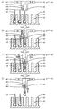
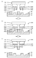
- FIG. 5 is an explanatory diagram of the operation of the mechanical chuck 40 when gripping the component P
- FIG. 5A is a diagram before gripping the component P
- FIG. 5C is a diagram in which the component P is gripped
- FIG. 5D is a diagram in which the component P is collected.
- control device 70 controls the X-axis slider 31 and the Y-axis slider 33 so that the mechanical chuck 40 comes directly above the component P (FIG. 5A).
- the control device 70 lowers the mechanical chuck 40 to bring the contact portion 46 of the cam follower 45 into contact with the upper surface 55 of the tray 52 (FIG. 5B).
- the predetermined position of the component P can be gripped by the first gripping member 43 and the second gripping member 47.
- the control device 70 moves the pair of support moving portions 37 (see FIG. 2) closer to each other so that the gripping surface 44 of the first gripping member 43 and the gripping surface 48 of the second gripping member 47 are components.
- the component P is brought into contact with P and gripped by the component P (FIG. 5C). Subsequently, the control device 70 raises the mechanical chuck 40, images the component P by the side camera 38, and grasps a deviation in the height direction of the component P held by the mechanical chuck 40. For example, depending on the positional displacement of the component P in the height direction, the imaging region of the side camera 38 must be changed. Here, since the part P is gripped at a stable position, the side camera 38 can capture the part P more reliably and correct the positional deviation in the height direction more reliably. Thereafter, the control device 70 controls the sliders 31 and 33 so that the component P gripped by the mechanical chuck 40 is directly above a predetermined position of the substrate 16, and corrects the gripping position shift of the component P to the position. P is placed.
- the tray 52 corresponds to the accommodating portion
- the cam follower 45 corresponds to the contact portion
- the first gripping member 43 and the second gripping member 47 correspond to the gripping portion
- the first holding member 41 and the second holding member corresponds to a holding member
- the control device 70 corresponds to a control unit
- the head holding body 36 corresponds to a head holding body.
- the mechanical chuck 40 collected by gripping the component P accommodated in the tray 52 in a state where the cam follower 45 and the tray 52 accommodating the component P are in contact with each other at a predetermined height position.
- the mechanical chuck 40 since the cam follower 45 and the tray 52 are in contact with each other, the component P is stably positioned at a height corresponding to a predetermined height. Therefore, the mechanical chuck 40 can grip the component P at a more stable grip position in the height direction. Further, the mechanical chuck 40 has a more adverse effect on the component P, such as deformation and breakage of the component P, compared to the case where the member is brought into contact with the component P to position the component P in the height direction.
- the position of the component may be displaced in the height direction as compared with the case where the component is sucked by the nozzle, for example, and the present invention is adopted. High significance.
- the mechanical chuck 40 abuts on the tray 52 by the cam follower 45, the first gripping member 43 and the second gripping member 47 can be moved smoothly, and the gripping position in the height direction is more stable. Easy to collect parts. Furthermore, since the mechanical chuck 40 is provided with the cam follower 45 on the first holding member 41, the mechanical chuck 40 can be changed in accordance with the type of the component so that the holding position in the height direction can be changed in a more stable state. Parts can be collected. Furthermore, since the mechanical chuck 40 is brought into contact with the tray 52 at two locations by the pair of cam followers 45, it is possible to grip the component more reliably at a more stable gripping position in the height direction.
- the present invention is not limited to the above-described embodiment, and it goes without saying that the present invention can be implemented in various modes as long as it belongs to the technical scope of the present invention.
- the same reference numerals are given to the same configurations as those in the above-described embodiment, and the detailed description thereof is omitted.
- FIG. 6A is a diagram before gripping the component P
- FIG. 6B is a diagram in which the component P is gripped by contacting the tray 52
- FIG. c) is a diagram in which a part P is collected.
- the mechanical chuck 40B includes a first holding member 41B and a second holding member 42B, and is configured as a holder that grips a predetermined position on the upper end side of the component P and collects the component P.
- the first holding member 41B includes a base and a support plate formed vertically downward from the base, and a first gripping claw 43B having a gripping surface in contact with the component P is disposed at the lower end of the support plate. It is installed.
- a columnar contact member 45B that contacts the upper surface 55 of the tray 52 that accommodates the component P at a predetermined height is formed in the vicinity of the first gripping claw 43B.
- the contact portion 46B that contacts the upper surface 55 of the tray 52 is the lower surface of the contact member 45B.
- the contact member 45B may have a columnar shape, a rod shape, or a wall shape.
- the second holding member 42B has the same configuration as the first holding member 41B, and includes a contact member 45B and a second gripping claw 47B.
- the control device 70 moves the mechanical chuck 40 directly above the component P (FIG. 6A).
- the control device 70 lowers the mechanical chuck 40B, causes the contact portion 46B of the contact member 45B to contact the upper surface 55 of the tray 52, and moves the pair of support moving portions 37 to approach each other.
- the part P is gripped by bringing the gripping surface of the first gripping claw 43B and the gripping surface of the second gripping claw 47B into contact with the part P (FIG. 6B).
- the control device 70 raises the mechanical chuck 40 ⁇ / b> B and collects the component P from the storage space 53 of the tray 52. Even in this case, in the mechanical chuck 40B, since the contact member 45B and the tray 52 are in contact with each other, the component P is stably positioned at a height corresponding to a predetermined height, and a more stable height. The component P can be gripped at the gripping position in the direction.
- the cam follower 45 is described as the contact portion.
- the mechanical chuck may include the cam follower 45 and the contact member 45B as the contact portion.
- the first holding member 41 is provided with the cam follower 45 and the second holding member 42 is not provided with the contact portion.
- the second holding member 42 is also provided with the cam follower 45 and the contact member 45B. It may be provided. If it carries out like this, the component P can be more reliably hold
- the cam follower 45 as the contact portion is brought into contact with the tray 52.
- the contact portion and the tray 52 may be pressed, or the tray 52 may be pressed at the contact portion. It is good also as a state which pressed more strongly. By so doing, it is possible to further suppress displacement in the height direction.
- the head unit 35 includes the mechanical chuck 40 having the first holding member 41 provided with the first holding member 43 and the second holding member 42 provided with the second holding member 47; And a head follower 36 to which the mechanical chuck 40 is mounted, and a cam follower 45 as a contact portion is disposed on the mechanical chuck 40.
- the contact portion may be disposed on the head holder 36.
- FIG. 7 is an explanatory diagram of another mechanical chuck 40C.
- the mechanical chuck 40C includes a first holding member 41C and a second holding member 42C.
- the first holding member 41C includes a first gripping claw 43C similar to the first holding member 41B.
- the second holding member 42C has the same configuration as the first holding member 41C and includes a second gripping claw 47C.
- a columnar contact member 45C that contacts the upper surface 55 of the tray 52 that accommodates the component P at a predetermined height position is disposed on the head holding body 36C.
- the contact portion 46C that contacts the upper surface 55 of the tray 52 is the lower surface of the contact member 45C. Even in this case, in the mechanical chuck 40C, the contact member 45C and the tray 52 are in contact with each other, so that the component P is stably positioned at a height corresponding to a predetermined height, and a more stable height.
- the component P can be gripped at the gripping position in the direction.
- the mechanical chuck 40 is provided with two cam followers 45 as contact portions, and is in contact with the tray 52 at two locations.
- the contact portion is at one location. It is good also as what contacts the tray 52, and it is good also as what contacts the tray 52 in three or more contact parts. Note that it is preferable that the abutting portion abuts on the tray 52 at two or more locations because it is less likely to cause a positional shift in the height direction.
- the positional relationship between the cam follower 45 as the contact portion and the first gripping member 43 has been described as being fixed.
- the present invention is not limited to this, and the height of the contact portion can be changed.
- a height adjustment mechanism may be provided. In this way, since a predetermined height position can be set according to various parts having different sizes in the height direction, various parts can be gripped and a more stable grip position in the height direction can be obtained. . Further, the mounting apparatus 11 is preferable because it is not necessary to prepare the mechanical chucks 40 corresponding to the respective components.
- the mounting apparatus 11 has been described as the present invention.
- the present invention is not particularly limited to this, and the mechanical chuck 40 may be used.
- the present invention can be used in the field of mounting electronic components.
- 10 component mounting system 11 mounting device, 12 LAN, 16 substrate, 20 substrate transport unit, 21 support plate, 22 conveyor belt, 25 substrate support unit, 30 head moving unit, 31 X axis slider, 32 guide rail, 33 Y axis Slider, 34 guide rail, 35 head unit, 36 head holder, 37 support moving part, 38 side camera, 39 joint, 40, 40B, 40C mechanical chuck, 41, 41B, 41C first holding member, 41a base, 41b Support plate, 42, 42B, 42C second holding member, 43 first gripping member, 43B, 43C first gripping claw, 44 gripping surface, 45 cam follower, 45B, 45C contact member, 46, 46B, 46C contact part, 47 Second gripping member, 47B, 4 C 2nd grip claw, 48 grip surface, 50 supply unit, 51 pallet, 52 tray, 53 storage space, 54 vertical groove, 55 top surface, 58 parts camera, 70 control device, 71 CPU, 72 ROM, 73 HDD, 74 RAM , 80 Management computer, A gripping area, P parts.
Landscapes
- Engineering & Computer Science (AREA)
- Manufacturing & Machinery (AREA)
- Microelectronics & Electronic Packaging (AREA)
- Supply And Installment Of Electrical Components (AREA)
- Manipulator (AREA)
Abstract
Description
部品を基板上の所定の実装位置に実装する実装処理を実行する実装装置であって、
部品を収容する収容部に所定の高さ位置で当接する当接部と、前記当接部と前記収容部とを当接した状態で前記収容部に収容された部品を把持部材により把持して採取する把持部と、を有するヘッドユニット、を備えたものである。
Claims (8)
- 部品を基板上の所定の実装位置に実装する実装処理を実行する実装装置であって、
部品を収容する収容部に所定の高さ位置で当接する当接部と、前記当接部と前記収容部とを当接した状態で前記収容部に収容された部品を把持して採取する把持部と、を有するヘッドユニット、を備えた実装装置。 - 前記当接部は、前記部品を採取する際に前記把持部が移動すると前記収容部と当接した状態で該移動に伴い回転するカムフォロアを有する、請求項1に記載の実装装置。
- 前記ヘッドユニットは、前記把持部が配設された保持部材と、前記保持部材を装着するヘッド保持体と、を有しており、
前記当接部は、前記保持部材に配設されている、請求項1又は2に記載の実装装置。 - 前記ヘッドユニットは、前記把持部が配設された保持部材と、前記保持部材を装着するヘッド保持体と、を有しており、
前記当接部は、前記ヘッド保持体に配設されている、請求項1~3のいずれか1項に記載の実装装置。 - 前記当接部は、2箇所以上で前記収容部と当接する、請求項1~4のいずれか1項に記載の実装装置。
- 前記ヘッドユニットは、前記当接部の前記所定の高さ位置を変更可能な高さ調節機構、を備える、請求項1~5のいずれか1項に記載の実装装置。
- 請求項1~6のいずれか1項に記載の実装装置であって、
前記当接部を前記収容部に当接させた状態で、該収容部に収容された部品を把持するよう前記把持部を移動させる制御手段、を備えた実装装置。 - 部品を基板上の所定の実装位置に実装する実装処理を実行する実装装置のヘッドユニットに装着される保持部材であって、
部品を収容する収容部に所定の高さ位置で当接する当接部と、前記当接部と前記収容部とを当接した状態で前記収容部に収容された部品を把持して採取する把持部と、を有する保持部材。
Priority Applications (5)
| Application Number | Priority Date | Filing Date | Title |
|---|---|---|---|
| US15/110,639 US10617049B2 (en) | 2014-01-17 | 2014-01-17 | Component mounting device and gripping members |
| EP14879128.8A EP3096595B1 (en) | 2014-01-17 | 2014-01-17 | Mounting device and holding member |
| JP2015557658A JP6204996B2 (ja) | 2014-01-17 | 2014-01-17 | 実装装置及び保持部材 |
| PCT/JP2014/050828 WO2015107680A1 (ja) | 2014-01-17 | 2014-01-17 | 実装装置及び保持部材 |
| CN201480072946.7A CN105900541B (zh) | 2014-01-17 | 2014-01-17 | 安装装置及保持部件 |
Applications Claiming Priority (1)
| Application Number | Priority Date | Filing Date | Title |
|---|---|---|---|
| PCT/JP2014/050828 WO2015107680A1 (ja) | 2014-01-17 | 2014-01-17 | 実装装置及び保持部材 |
Publications (1)
| Publication Number | Publication Date |
|---|---|
| WO2015107680A1 true WO2015107680A1 (ja) | 2015-07-23 |
Family
ID=53542598
Family Applications (1)
| Application Number | Title | Priority Date | Filing Date |
|---|---|---|---|
| PCT/JP2014/050828 WO2015107680A1 (ja) | 2014-01-17 | 2014-01-17 | 実装装置及び保持部材 |
Country Status (5)
| Country | Link |
|---|---|
| US (1) | US10617049B2 (ja) |
| EP (1) | EP3096595B1 (ja) |
| JP (1) | JP6204996B2 (ja) |
| CN (1) | CN105900541B (ja) |
| WO (1) | WO2015107680A1 (ja) |
Cited By (1)
| Publication number | Priority date | Publication date | Assignee | Title |
|---|---|---|---|---|
| JP2019126859A (ja) * | 2018-01-22 | 2019-08-01 | 川崎重工業株式会社 | ロボットハンド |
Families Citing this family (1)
| Publication number | Priority date | Publication date | Assignee | Title |
|---|---|---|---|---|
| US10617049B2 (en) * | 2014-01-17 | 2020-04-07 | Fuji Corporation | Component mounting device and gripping members |
Citations (5)
| Publication number | Priority date | Publication date | Assignee | Title |
|---|---|---|---|---|
| JPS63236400A (ja) * | 1987-03-13 | 1988-10-03 | エヌ・ベー・フィリップス・フルーイランペンファブリケン | 把持装置 |
| JP2003025266A (ja) | 2001-07-19 | 2003-01-29 | Fuji Mach Mfg Co Ltd | 電動チャック |
| JP2004319739A (ja) * | 2003-04-16 | 2004-11-11 | Fuji Electric Holdings Co Ltd | 電子部品挿入装置の電子部品挿入方法 |
| JP2005108959A (ja) * | 2003-09-29 | 2005-04-21 | Hitachi High-Tech Instruments Co Ltd | 電子部品装着装置 |
| JP2012084701A (ja) * | 2010-10-12 | 2012-04-26 | Fujitsu Ltd | 部品実装装置及び部品実装方法 |
Family Cites Families (14)
| Publication number | Priority date | Publication date | Assignee | Title |
|---|---|---|---|---|
| JPH0691355B2 (ja) * | 1988-01-19 | 1994-11-14 | 三洋電機株式会社 | 電子部品位置決め装置 |
| US5509193A (en) * | 1994-05-06 | 1996-04-23 | Micron Technology, Inc. | Apparatus for loading and unloading burn-in boards |
| JP2930565B2 (ja) * | 1996-10-05 | 1999-08-03 | 三星電子株式会社 | サーボモータを用いた半導体チップパッケージのローディング及びアンローディング装置 |
| JP4546663B2 (ja) * | 2001-04-23 | 2010-09-15 | 富士機械製造株式会社 | プリント板保持装置および電気部品装着システム |
| JP2003031992A (ja) * | 2001-07-17 | 2003-01-31 | Fuji Mach Mfg Co Ltd | 電気部品載置方法および電気部品載置装置 |
| SG148033A1 (en) * | 2001-12-28 | 2008-12-31 | Panasonic Corp | Mounting apparatus |
| US7350289B2 (en) * | 2002-12-02 | 2008-04-01 | Matsushita Electric Industrial Co., Ltd. | Component feeding head apparatus, for holding a component arrayed |
| CN100399038C (zh) * | 2002-12-25 | 2008-07-02 | 株式会社理光 | 集成电路传送装置 |
| US20040183320A1 (en) * | 2003-03-19 | 2004-09-23 | Brian Evans | Bi-directional gripping of rectangular devices/components |
| JP4516354B2 (ja) * | 2004-05-17 | 2010-08-04 | パナソニック株式会社 | 部品供給方法 |
| JP2006269793A (ja) * | 2005-03-24 | 2006-10-05 | Yamagata Casio Co Ltd | 電子部品のクランプヘッド及び部品実装装置 |
| US7337534B2 (en) | 2005-04-07 | 2008-03-04 | Chi Ming Wong | SMD chip handling apparatus |
| JP4726241B2 (ja) * | 2007-02-16 | 2011-07-20 | シュンク・ジャパン株式会社 | 産業用ロボットのロボットハンド |
| US10617049B2 (en) * | 2014-01-17 | 2020-04-07 | Fuji Corporation | Component mounting device and gripping members |
-
2014
- 2014-01-17 US US15/110,639 patent/US10617049B2/en active Active
- 2014-01-17 JP JP2015557658A patent/JP6204996B2/ja active Active
- 2014-01-17 EP EP14879128.8A patent/EP3096595B1/en active Active
- 2014-01-17 CN CN201480072946.7A patent/CN105900541B/zh active Active
- 2014-01-17 WO PCT/JP2014/050828 patent/WO2015107680A1/ja active Application Filing
Patent Citations (5)
| Publication number | Priority date | Publication date | Assignee | Title |
|---|---|---|---|---|
| JPS63236400A (ja) * | 1987-03-13 | 1988-10-03 | エヌ・ベー・フィリップス・フルーイランペンファブリケン | 把持装置 |
| JP2003025266A (ja) | 2001-07-19 | 2003-01-29 | Fuji Mach Mfg Co Ltd | 電動チャック |
| JP2004319739A (ja) * | 2003-04-16 | 2004-11-11 | Fuji Electric Holdings Co Ltd | 電子部品挿入装置の電子部品挿入方法 |
| JP2005108959A (ja) * | 2003-09-29 | 2005-04-21 | Hitachi High-Tech Instruments Co Ltd | 電子部品装着装置 |
| JP2012084701A (ja) * | 2010-10-12 | 2012-04-26 | Fujitsu Ltd | 部品実装装置及び部品実装方法 |
Cited By (1)
| Publication number | Priority date | Publication date | Assignee | Title |
|---|---|---|---|---|
| JP2019126859A (ja) * | 2018-01-22 | 2019-08-01 | 川崎重工業株式会社 | ロボットハンド |
Also Published As
| Publication number | Publication date |
|---|---|
| EP3096595A1 (en) | 2016-11-23 |
| EP3096595A4 (en) | 2016-12-14 |
| US10617049B2 (en) | 2020-04-07 |
| CN105900541A (zh) | 2016-08-24 |
| EP3096595B1 (en) | 2019-08-07 |
| US20160330881A1 (en) | 2016-11-10 |
| JPWO2015107680A1 (ja) | 2017-03-23 |
| JP6204996B2 (ja) | 2017-09-27 |
| CN105900541B (zh) | 2019-07-09 |
Similar Documents
| Publication | Publication Date | Title |
|---|---|---|
| JP6542353B2 (ja) | 部品供給装置 | |
| US20170238448A1 (en) | Component supply device | |
| JP6577965B2 (ja) | 部品供給装置、および保持具決定方法 | |
| WO2016046897A1 (ja) | 部品供給システム | |
| JP6522653B2 (ja) | 作業機、および収納方法 | |
| US10555447B2 (en) | Component supply device that supplies components from a scattered state and mounting machine that mounts the component | |
| JP6053572B2 (ja) | 実装装置及び実装方法 | |
| JP6204996B2 (ja) | 実装装置及び保持部材 | |
| JP6571176B2 (ja) | 部品実装機、および部品実装機の部品供給方法 | |
| WO2017094107A1 (ja) | ワーク移載装置及びワーク移載システム | |
| JP6009695B2 (ja) | 部品実装装置、部品実装方法 | |
| WO2017051446A1 (ja) | 部品供給システム | |
| WO2022054202A1 (ja) | 表示装置、および干渉確認方法 | |
| JP2017168712A (ja) | 部品供給システム | |
| JP2019197929A (ja) | 部品保持装置、および吸着ノズル決定方法 | |
| JP2019197930A (ja) | 部品保持装置、および保持具決定方法 | |
| JP6423193B2 (ja) | 実装装置及び実装方法 | |
| JP7014854B2 (ja) | 散在部品のピッキング装置、および散在部品のピッキング方法 | |
| JP6857767B2 (ja) | 散在部品のピッキング装置、および部品保持具の交換方法 | |
| JP6858273B2 (ja) | 作業機、装着方法 | |
| JP7095109B2 (ja) | 作業機、および演算方法 | |
| JP2019057743A (ja) | 部品保持装置 | |
| JP2019057744A (ja) | 部品保持装置 | |
| JP2017112285A (ja) | 実装設定装置及び実装設定方法 | |
| JP2017130601A (ja) | 部品実装装置 |
Legal Events
| Date | Code | Title | Description |
|---|---|---|---|
| 121 | Ep: the epo has been informed by wipo that ep was designated in this application |
Ref document number: 14879128 Country of ref document: EP Kind code of ref document: A1 |
|
| ENP | Entry into the national phase |
Ref document number: 2015557658 Country of ref document: JP Kind code of ref document: A |
|
| REEP | Request for entry into the european phase |
Ref document number: 2014879128 Country of ref document: EP |
|
| WWE | Wipo information: entry into national phase |
Ref document number: 2014879128 Country of ref document: EP |
|
| WWE | Wipo information: entry into national phase |
Ref document number: 15110639 Country of ref document: US |
|
| NENP | Non-entry into the national phase |
Ref country code: DE |