EP3095417A1 - Teilweise resorbierbare implantate und verfahren - Google Patents
Teilweise resorbierbare implantate und verfahren Download PDFInfo
- Publication number
- EP3095417A1 EP3095417A1 EP16170075.2A EP16170075A EP3095417A1 EP 3095417 A1 EP3095417 A1 EP 3095417A1 EP 16170075 A EP16170075 A EP 16170075A EP 3095417 A1 EP3095417 A1 EP 3095417A1
- Authority
- EP
- European Patent Office
- Prior art keywords
- framework
- implant
- resorbable
- component
- bone
- Prior art date
- Legal status (The legal status is an assumption and is not a legal conclusion. Google has not performed a legal analysis and makes no representation as to the accuracy of the status listed.)
- Granted
Links
Images










Classifications
-
- A—HUMAN NECESSITIES
- A61—MEDICAL OR VETERINARY SCIENCE; HYGIENE
- A61L—METHODS OR APPARATUS FOR STERILISING MATERIALS OR OBJECTS IN GENERAL; DISINFECTION, STERILISATION OR DEODORISATION OF AIR; CHEMICAL ASPECTS OF BANDAGES, DRESSINGS, ABSORBENT PADS OR SURGICAL ARTICLES; MATERIALS FOR BANDAGES, DRESSINGS, ABSORBENT PADS OR SURGICAL ARTICLES
- A61L27/00—Materials for grafts or prostheses or for coating grafts or prostheses
- A61L27/50—Materials characterised by their function or physical properties, e.g. injectable or lubricating compositions, shape-memory materials, surface modified materials
- A61L27/58—Materials at least partially resorbable by the body
-
- A—HUMAN NECESSITIES
- A61—MEDICAL OR VETERINARY SCIENCE; HYGIENE
- A61F—FILTERS IMPLANTABLE INTO BLOOD VESSELS; PROSTHESES; DEVICES PROVIDING PATENCY TO, OR PREVENTING COLLAPSING OF, TUBULAR STRUCTURES OF THE BODY, e.g. STENTS; ORTHOPAEDIC, NURSING OR CONTRACEPTIVE DEVICES; FOMENTATION; TREATMENT OR PROTECTION OF EYES OR EARS; BANDAGES, DRESSINGS OR ABSORBENT PADS; FIRST-AID KITS
- A61F2/00—Filters implantable into blood vessels; Prostheses, i.e. artificial substitutes or replacements for parts of the body; Appliances for connecting them with the body; Devices providing patency to, or preventing collapsing of, tubular structures of the body, e.g. stents
- A61F2/02—Prostheses implantable into the body
- A61F2/30—Joints
- A61F2/44—Joints for the spine, e.g. vertebrae, spinal discs
-
- A—HUMAN NECESSITIES
- A61—MEDICAL OR VETERINARY SCIENCE; HYGIENE
- A61F—FILTERS IMPLANTABLE INTO BLOOD VESSELS; PROSTHESES; DEVICES PROVIDING PATENCY TO, OR PREVENTING COLLAPSING OF, TUBULAR STRUCTURES OF THE BODY, e.g. STENTS; ORTHOPAEDIC, NURSING OR CONTRACEPTIVE DEVICES; FOMENTATION; TREATMENT OR PROTECTION OF EYES OR EARS; BANDAGES, DRESSINGS OR ABSORBENT PADS; FIRST-AID KITS
- A61F2/00—Filters implantable into blood vessels; Prostheses, i.e. artificial substitutes or replacements for parts of the body; Appliances for connecting them with the body; Devices providing patency to, or preventing collapsing of, tubular structures of the body, e.g. stents
- A61F2/02—Prostheses implantable into the body
- A61F2/30—Joints
- A61F2/44—Joints for the spine, e.g. vertebrae, spinal discs
- A61F2/4455—Joints for the spine, e.g. vertebrae, spinal discs for the fusion of spinal bodies, e.g. intervertebral fusion of adjacent spinal bodies, e.g. fusion cages
- A61F2/4465—Joints for the spine, e.g. vertebrae, spinal discs for the fusion of spinal bodies, e.g. intervertebral fusion of adjacent spinal bodies, e.g. fusion cages having a circular or kidney shaped cross-section substantially perpendicular to the axis of the spine
-
- A—HUMAN NECESSITIES
- A61—MEDICAL OR VETERINARY SCIENCE; HYGIENE
- A61F—FILTERS IMPLANTABLE INTO BLOOD VESSELS; PROSTHESES; DEVICES PROVIDING PATENCY TO, OR PREVENTING COLLAPSING OF, TUBULAR STRUCTURES OF THE BODY, e.g. STENTS; ORTHOPAEDIC, NURSING OR CONTRACEPTIVE DEVICES; FOMENTATION; TREATMENT OR PROTECTION OF EYES OR EARS; BANDAGES, DRESSINGS OR ABSORBENT PADS; FIRST-AID KITS
- A61F2/00—Filters implantable into blood vessels; Prostheses, i.e. artificial substitutes or replacements for parts of the body; Appliances for connecting them with the body; Devices providing patency to, or preventing collapsing of, tubular structures of the body, e.g. stents
- A61F2/02—Prostheses implantable into the body
- A61F2/30—Joints
- A61F2/44—Joints for the spine, e.g. vertebrae, spinal discs
- A61F2/4455—Joints for the spine, e.g. vertebrae, spinal discs for the fusion of spinal bodies, e.g. intervertebral fusion of adjacent spinal bodies, e.g. fusion cages
- A61F2/447—Joints for the spine, e.g. vertebrae, spinal discs for the fusion of spinal bodies, e.g. intervertebral fusion of adjacent spinal bodies, e.g. fusion cages substantially parallelepipedal, e.g. having a rectangular or trapezoidal cross-section
-
- A—HUMAN NECESSITIES
- A61—MEDICAL OR VETERINARY SCIENCE; HYGIENE
- A61F—FILTERS IMPLANTABLE INTO BLOOD VESSELS; PROSTHESES; DEVICES PROVIDING PATENCY TO, OR PREVENTING COLLAPSING OF, TUBULAR STRUCTURES OF THE BODY, e.g. STENTS; ORTHOPAEDIC, NURSING OR CONTRACEPTIVE DEVICES; FOMENTATION; TREATMENT OR PROTECTION OF EYES OR EARS; BANDAGES, DRESSINGS OR ABSORBENT PADS; FIRST-AID KITS
- A61F2/00—Filters implantable into blood vessels; Prostheses, i.e. artificial substitutes or replacements for parts of the body; Appliances for connecting them with the body; Devices providing patency to, or preventing collapsing of, tubular structures of the body, e.g. stents
- A61F2/02—Prostheses implantable into the body
- A61F2/30—Joints
- A61F2/44—Joints for the spine, e.g. vertebrae, spinal discs
- A61F2/4455—Joints for the spine, e.g. vertebrae, spinal discs for the fusion of spinal bodies, e.g. intervertebral fusion of adjacent spinal bodies, e.g. fusion cages
-
- A—HUMAN NECESSITIES
- A61—MEDICAL OR VETERINARY SCIENCE; HYGIENE
- A61F—FILTERS IMPLANTABLE INTO BLOOD VESSELS; PROSTHESES; DEVICES PROVIDING PATENCY TO, OR PREVENTING COLLAPSING OF, TUBULAR STRUCTURES OF THE BODY, e.g. STENTS; ORTHOPAEDIC, NURSING OR CONTRACEPTIVE DEVICES; FOMENTATION; TREATMENT OR PROTECTION OF EYES OR EARS; BANDAGES, DRESSINGS OR ABSORBENT PADS; FIRST-AID KITS
- A61F2/00—Filters implantable into blood vessels; Prostheses, i.e. artificial substitutes or replacements for parts of the body; Appliances for connecting them with the body; Devices providing patency to, or preventing collapsing of, tubular structures of the body, e.g. stents
- A61F2/02—Prostheses implantable into the body
- A61F2/30—Joints
- A61F2002/30001—Additional features of subject-matter classified in A61F2/28, A61F2/30 and subgroups thereof
- A61F2002/30003—Material related properties of the prosthesis or of a coating on the prosthesis
- A61F2002/30004—Material related properties of the prosthesis or of a coating on the prosthesis the prosthesis being made from materials having different values of a given property at different locations within the same prosthesis
- A61F2002/30032—Material related properties of the prosthesis or of a coating on the prosthesis the prosthesis being made from materials having different values of a given property at different locations within the same prosthesis differing in absorbability or resorbability, i.e. in absorption or resorption time
-
- A—HUMAN NECESSITIES
- A61—MEDICAL OR VETERINARY SCIENCE; HYGIENE
- A61F—FILTERS IMPLANTABLE INTO BLOOD VESSELS; PROSTHESES; DEVICES PROVIDING PATENCY TO, OR PREVENTING COLLAPSING OF, TUBULAR STRUCTURES OF THE BODY, e.g. STENTS; ORTHOPAEDIC, NURSING OR CONTRACEPTIVE DEVICES; FOMENTATION; TREATMENT OR PROTECTION OF EYES OR EARS; BANDAGES, DRESSINGS OR ABSORBENT PADS; FIRST-AID KITS
- A61F2/00—Filters implantable into blood vessels; Prostheses, i.e. artificial substitutes or replacements for parts of the body; Appliances for connecting them with the body; Devices providing patency to, or preventing collapsing of, tubular structures of the body, e.g. stents
- A61F2/02—Prostheses implantable into the body
- A61F2/30—Joints
- A61F2002/30001—Additional features of subject-matter classified in A61F2/28, A61F2/30 and subgroups thereof
- A61F2002/30003—Material related properties of the prosthesis or of a coating on the prosthesis
- A61F2002/3006—Properties of materials and coating materials
- A61F2002/3008—Properties of materials and coating materials radio-opaque, e.g. radio-opaque markers
-
- A—HUMAN NECESSITIES
- A61—MEDICAL OR VETERINARY SCIENCE; HYGIENE
- A61F—FILTERS IMPLANTABLE INTO BLOOD VESSELS; PROSTHESES; DEVICES PROVIDING PATENCY TO, OR PREVENTING COLLAPSING OF, TUBULAR STRUCTURES OF THE BODY, e.g. STENTS; ORTHOPAEDIC, NURSING OR CONTRACEPTIVE DEVICES; FOMENTATION; TREATMENT OR PROTECTION OF EYES OR EARS; BANDAGES, DRESSINGS OR ABSORBENT PADS; FIRST-AID KITS
- A61F2/00—Filters implantable into blood vessels; Prostheses, i.e. artificial substitutes or replacements for parts of the body; Appliances for connecting them with the body; Devices providing patency to, or preventing collapsing of, tubular structures of the body, e.g. stents
- A61F2/02—Prostheses implantable into the body
- A61F2/30—Joints
- A61F2002/30001—Additional features of subject-matter classified in A61F2/28, A61F2/30 and subgroups thereof
- A61F2002/30108—Shapes
- A61F2002/3011—Cross-sections or two-dimensional shapes
- A61F2002/30112—Rounded shapes, e.g. with rounded corners
- A61F2002/30133—Rounded shapes, e.g. with rounded corners kidney-shaped or bean-shaped
-
- A—HUMAN NECESSITIES
- A61—MEDICAL OR VETERINARY SCIENCE; HYGIENE
- A61F—FILTERS IMPLANTABLE INTO BLOOD VESSELS; PROSTHESES; DEVICES PROVIDING PATENCY TO, OR PREVENTING COLLAPSING OF, TUBULAR STRUCTURES OF THE BODY, e.g. STENTS; ORTHOPAEDIC, NURSING OR CONTRACEPTIVE DEVICES; FOMENTATION; TREATMENT OR PROTECTION OF EYES OR EARS; BANDAGES, DRESSINGS OR ABSORBENT PADS; FIRST-AID KITS
- A61F2/00—Filters implantable into blood vessels; Prostheses, i.e. artificial substitutes or replacements for parts of the body; Appliances for connecting them with the body; Devices providing patency to, or preventing collapsing of, tubular structures of the body, e.g. stents
- A61F2/02—Prostheses implantable into the body
- A61F2/30—Joints
- A61F2002/30001—Additional features of subject-matter classified in A61F2/28, A61F2/30 and subgroups thereof
- A61F2002/30108—Shapes
- A61F2002/30199—Three-dimensional shapes
- A61F2002/30224—Three-dimensional shapes cylindrical
- A61F2002/30235—Three-dimensional shapes cylindrical tubular, e.g. sleeves
-
- A—HUMAN NECESSITIES
- A61—MEDICAL OR VETERINARY SCIENCE; HYGIENE
- A61F—FILTERS IMPLANTABLE INTO BLOOD VESSELS; PROSTHESES; DEVICES PROVIDING PATENCY TO, OR PREVENTING COLLAPSING OF, TUBULAR STRUCTURES OF THE BODY, e.g. STENTS; ORTHOPAEDIC, NURSING OR CONTRACEPTIVE DEVICES; FOMENTATION; TREATMENT OR PROTECTION OF EYES OR EARS; BANDAGES, DRESSINGS OR ABSORBENT PADS; FIRST-AID KITS
- A61F2/00—Filters implantable into blood vessels; Prostheses, i.e. artificial substitutes or replacements for parts of the body; Appliances for connecting them with the body; Devices providing patency to, or preventing collapsing of, tubular structures of the body, e.g. stents
- A61F2/02—Prostheses implantable into the body
- A61F2/30—Joints
- A61F2002/30001—Additional features of subject-matter classified in A61F2/28, A61F2/30 and subgroups thereof
- A61F2002/30316—The prosthesis having different structural features at different locations within the same prosthesis; Connections between prosthetic parts; Special structural features of bone or joint prostheses not otherwise provided for
- A61F2002/30329—Connections or couplings between prosthetic parts, e.g. between modular parts; Connecting elements
- A61F2002/30383—Connections or couplings between prosthetic parts, e.g. between modular parts; Connecting elements made by laterally inserting a protrusion, e.g. a rib into a complementarily-shaped groove
- A61F2002/30387—Dovetail connection
-
- A—HUMAN NECESSITIES
- A61—MEDICAL OR VETERINARY SCIENCE; HYGIENE
- A61F—FILTERS IMPLANTABLE INTO BLOOD VESSELS; PROSTHESES; DEVICES PROVIDING PATENCY TO, OR PREVENTING COLLAPSING OF, TUBULAR STRUCTURES OF THE BODY, e.g. STENTS; ORTHOPAEDIC, NURSING OR CONTRACEPTIVE DEVICES; FOMENTATION; TREATMENT OR PROTECTION OF EYES OR EARS; BANDAGES, DRESSINGS OR ABSORBENT PADS; FIRST-AID KITS
- A61F2/00—Filters implantable into blood vessels; Prostheses, i.e. artificial substitutes or replacements for parts of the body; Appliances for connecting them with the body; Devices providing patency to, or preventing collapsing of, tubular structures of the body, e.g. stents
- A61F2/02—Prostheses implantable into the body
- A61F2/30—Joints
- A61F2002/30001—Additional features of subject-matter classified in A61F2/28, A61F2/30 and subgroups thereof
- A61F2002/30667—Features concerning an interaction with the environment or a particular use of the prosthesis
- A61F2002/30677—Means for introducing or releasing pharmaceutical products, e.g. antibiotics, into the body
-
- A—HUMAN NECESSITIES
- A61—MEDICAL OR VETERINARY SCIENCE; HYGIENE
- A61F—FILTERS IMPLANTABLE INTO BLOOD VESSELS; PROSTHESES; DEVICES PROVIDING PATENCY TO, OR PREVENTING COLLAPSING OF, TUBULAR STRUCTURES OF THE BODY, e.g. STENTS; ORTHOPAEDIC, NURSING OR CONTRACEPTIVE DEVICES; FOMENTATION; TREATMENT OR PROTECTION OF EYES OR EARS; BANDAGES, DRESSINGS OR ABSORBENT PADS; FIRST-AID KITS
- A61F2/00—Filters implantable into blood vessels; Prostheses, i.e. artificial substitutes or replacements for parts of the body; Appliances for connecting them with the body; Devices providing patency to, or preventing collapsing of, tubular structures of the body, e.g. stents
- A61F2/02—Prostheses implantable into the body
- A61F2/30—Joints
- A61F2/30767—Special external or bone-contacting surface, e.g. coating for improving bone ingrowth
- A61F2/30771—Special external or bone-contacting surface, e.g. coating for improving bone ingrowth applied in original prostheses, e.g. holes or grooves
- A61F2002/30878—Special external or bone-contacting surface, e.g. coating for improving bone ingrowth applied in original prostheses, e.g. holes or grooves with non-sharp protrusions, for instance contacting the bone for anchoring, e.g. keels, pegs, pins, posts, shanks, stems, struts
- A61F2002/30879—Ribs
- A61F2002/30883—Ribs dovetail-shaped
-
- A—HUMAN NECESSITIES
- A61—MEDICAL OR VETERINARY SCIENCE; HYGIENE
- A61F—FILTERS IMPLANTABLE INTO BLOOD VESSELS; PROSTHESES; DEVICES PROVIDING PATENCY TO, OR PREVENTING COLLAPSING OF, TUBULAR STRUCTURES OF THE BODY, e.g. STENTS; ORTHOPAEDIC, NURSING OR CONTRACEPTIVE DEVICES; FOMENTATION; TREATMENT OR PROTECTION OF EYES OR EARS; BANDAGES, DRESSINGS OR ABSORBENT PADS; FIRST-AID KITS
- A61F2/00—Filters implantable into blood vessels; Prostheses, i.e. artificial substitutes or replacements for parts of the body; Appliances for connecting them with the body; Devices providing patency to, or preventing collapsing of, tubular structures of the body, e.g. stents
- A61F2/02—Prostheses implantable into the body
- A61F2/30—Joints
- A61F2/30767—Special external or bone-contacting surface, e.g. coating for improving bone ingrowth
- A61F2/30771—Special external or bone-contacting surface, e.g. coating for improving bone ingrowth applied in original prostheses, e.g. holes or grooves
- A61F2002/30878—Special external or bone-contacting surface, e.g. coating for improving bone ingrowth applied in original prostheses, e.g. holes or grooves with non-sharp protrusions, for instance contacting the bone for anchoring, e.g. keels, pegs, pins, posts, shanks, stems, struts
- A61F2002/30884—Fins or wings, e.g. longitudinal wings for preventing rotation within the bone cavity
-
- A—HUMAN NECESSITIES
- A61—MEDICAL OR VETERINARY SCIENCE; HYGIENE
- A61F—FILTERS IMPLANTABLE INTO BLOOD VESSELS; PROSTHESES; DEVICES PROVIDING PATENCY TO, OR PREVENTING COLLAPSING OF, TUBULAR STRUCTURES OF THE BODY, e.g. STENTS; ORTHOPAEDIC, NURSING OR CONTRACEPTIVE DEVICES; FOMENTATION; TREATMENT OR PROTECTION OF EYES OR EARS; BANDAGES, DRESSINGS OR ABSORBENT PADS; FIRST-AID KITS
- A61F2/00—Filters implantable into blood vessels; Prostheses, i.e. artificial substitutes or replacements for parts of the body; Appliances for connecting them with the body; Devices providing patency to, or preventing collapsing of, tubular structures of the body, e.g. stents
- A61F2/02—Prostheses implantable into the body
- A61F2/30—Joints
- A61F2/30767—Special external or bone-contacting surface, e.g. coating for improving bone ingrowth
- A61F2/30771—Special external or bone-contacting surface, e.g. coating for improving bone ingrowth applied in original prostheses, e.g. holes or grooves
- A61F2002/30904—Special external or bone-contacting surface, e.g. coating for improving bone ingrowth applied in original prostheses, e.g. holes or grooves serrated profile, i.e. saw-toothed
-
- A—HUMAN NECESSITIES
- A61—MEDICAL OR VETERINARY SCIENCE; HYGIENE
- A61F—FILTERS IMPLANTABLE INTO BLOOD VESSELS; PROSTHESES; DEVICES PROVIDING PATENCY TO, OR PREVENTING COLLAPSING OF, TUBULAR STRUCTURES OF THE BODY, e.g. STENTS; ORTHOPAEDIC, NURSING OR CONTRACEPTIVE DEVICES; FOMENTATION; TREATMENT OR PROTECTION OF EYES OR EARS; BANDAGES, DRESSINGS OR ABSORBENT PADS; FIRST-AID KITS
- A61F2/00—Filters implantable into blood vessels; Prostheses, i.e. artificial substitutes or replacements for parts of the body; Appliances for connecting them with the body; Devices providing patency to, or preventing collapsing of, tubular structures of the body, e.g. stents
- A61F2/02—Prostheses implantable into the body
- A61F2/30—Joints
- A61F2/46—Special tools for implanting artificial joints
- A61F2/4603—Special tools for implanting artificial joints for insertion or extraction of endoprosthetic joints or of accessories thereof
- A61F2002/4629—Special tools for implanting artificial joints for insertion or extraction of endoprosthetic joints or of accessories thereof connected to the endoprosthesis or implant via a threaded connection
-
- A—HUMAN NECESSITIES
- A61—MEDICAL OR VETERINARY SCIENCE; HYGIENE
- A61F—FILTERS IMPLANTABLE INTO BLOOD VESSELS; PROSTHESES; DEVICES PROVIDING PATENCY TO, OR PREVENTING COLLAPSING OF, TUBULAR STRUCTURES OF THE BODY, e.g. STENTS; ORTHOPAEDIC, NURSING OR CONTRACEPTIVE DEVICES; FOMENTATION; TREATMENT OR PROTECTION OF EYES OR EARS; BANDAGES, DRESSINGS OR ABSORBENT PADS; FIRST-AID KITS
- A61F2/00—Filters implantable into blood vessels; Prostheses, i.e. artificial substitutes or replacements for parts of the body; Appliances for connecting them with the body; Devices providing patency to, or preventing collapsing of, tubular structures of the body, e.g. stents
- A61F2/02—Prostheses implantable into the body
- A61F2/30—Joints
- A61F2/46—Special tools for implanting artificial joints
- A61F2002/4631—Special tools for implanting artificial joints the prosthesis being specially adapted for being cemented
-
- A—HUMAN NECESSITIES
- A61—MEDICAL OR VETERINARY SCIENCE; HYGIENE
- A61L—METHODS OR APPARATUS FOR STERILISING MATERIALS OR OBJECTS IN GENERAL; DISINFECTION, STERILISATION OR DEODORISATION OF AIR; CHEMICAL ASPECTS OF BANDAGES, DRESSINGS, ABSORBENT PADS OR SURGICAL ARTICLES; MATERIALS FOR BANDAGES, DRESSINGS, ABSORBENT PADS OR SURGICAL ARTICLES
- A61L2430/00—Materials or treatment for tissue regeneration
- A61L2430/38—Materials or treatment for tissue regeneration for reconstruction of the spine, vertebrae or intervertebral discs
-
- A—HUMAN NECESSITIES
- A61—MEDICAL OR VETERINARY SCIENCE; HYGIENE
- A61L—METHODS OR APPARATUS FOR STERILISING MATERIALS OR OBJECTS IN GENERAL; DISINFECTION, STERILISATION OR DEODORISATION OF AIR; CHEMICAL ASPECTS OF BANDAGES, DRESSINGS, ABSORBENT PADS OR SURGICAL ARTICLES; MATERIALS FOR BANDAGES, DRESSINGS, ABSORBENT PADS OR SURGICAL ARTICLES
- A61L27/00—Materials for grafts or prostheses or for coating grafts or prostheses
- A61L27/50—Materials characterised by their function or physical properties, e.g. injectable or lubricating compositions, shape-memory materials, surface modified materials
Definitions
- the present invention relates to spinal surgery, namely the fusion of adjacent intervertebral bodies or the replacement of a vertebral body.
- Back pain can be caused by many different maladies, not the least of which are problems that directly impact the intervertebral discs of the spine.
- Typical disc issues include, inter alia, degeneration, bulging, herniation, thinning, abnormal movement, spondylosis, spinal stenosis, disc herniation, retrolisthesis, and discogenic back pain.
- One method of treatment of such disc problems that is widely utilized in the field of spinal surgery is a spinal fusion procedure, whereby an affected disc is removed, and the adjacent vertebral bodies are fused together through the use of interbody spacers, implants, or the like. In some instances, it may also be necessary to remove and replace an entire vertebral body. This is often accomplished through the use of a larger implant that acts to fuse together the vertebral bodies adjacent the removed vertebral body.
- a first aspect of the invention includes an implant sized and adapted for insertion into an intervertebral space between adjacent vertebral bodies.
- the implant comprises a non-resorbable, structural framework having top and bottom bone-contacting surfaces and a plurality of struts defining geometric openings between the top and bottom surfaces, the struts providing structural support for the framework, wherein the framework includes a plurality of support columns extending between proximal and distal ends of the framework, the plurality of support columns being spaced apart from each other to define vertical openings in the framework.
- the implant also includes a resorbable material component within and/or around the framework for resorption and formation of new bone to fuse the vertebral bodies together.
- the resorbable material component is a structural component that includes top and bottom bone-contacting surfaces configured to support post-surgical loads experienced after implantation of the implant.
- a second aspect of the invention includes an implant sized and adapted for insertion into an intervertebral space between adjacent vertebral bodies.
- the implant comprises a non-resorbable, non-structural framework having top and bottom bone-contacting surfaces formed of a porous material, and a resorbable, structural component positioned between the top and bottom surfaces of the framework to provide structural support for the top and bottom surfaces and the implant.
- the top and bottom surfaces of the framework are two millimeters (2 mm) or less in thickness.
- a third aspect of the invention includes an implant sized and adapted for insertion into an intervertebral space between adjacent vertebral bodies.
- the implant comprises a non-structural, non-resorbable framework having a main body and a fluid conduit within the main body, the main body having an injection port in fluid communication with the fluid conduit.
- the implant also includes a resorbable, structural component having top and bottom bone-contacting surfaces and an opening in at least one of the top and bottom surfaces, the opening being in fluid communication with the fluid conduit.
- a fluid conduit projects outward from the main body and is fluidly connected with the fluid conduit in the main body, wherein the outwardly-projecting fluid conduit defines the opening in the at least one of the top and bottom surfaces of the resorbable, structural component.
- a fourth aspect of the invention includes an implant sized and adapted for insertion into an intervertebral space between adjacent vertebral bodies.
- the implant comprises a non-structural, non-resorbable framework having a series of ring members connected together by way of a plurality of struts, and a resorbable, structural component embedded with and/or around the framework for encouraging resorption of the implant and fusion of the vertebral bodies.
- the ring members are arranged transverse to a longitudinal axis of the framework, and the struts extend along the longitudinal axis and connect the ring members.
- a fifth aspect of the invention includes a method of reducing subsidence of an implant into bone.
- the method comprises providing an implant having a non-resorbable structural framework and a resorbable structural component positioned within and/or around the framework.
- the framework is implanted between first and second adjacent vertebral bodies so that top and bottom surfaces of the framework contact vertebral endplates of the first and second vertebral bodies, and the resorbable component is likewise implanted between the first and second adjacent vertebral bodies so that top and bottom surfaces of the resorbable component contact the vertebral endplates.
- the top and bottom surfaces of the resorbable component contact the vertebral endplates over a contact surface area sufficient to reduce peak stresses between the framework and the vertebral bodies by an amount effective to eliminate or reduce subsidence of the framework into the vertebral bodies.
- peak stresses between the framework and the vertebral bodies is above a stress required for the vertebral endplates to fail, for example above 160 MPa.
- a sixth aspect of the invention includes an implant sized and adapted for insertion into an intervertebral space between adjacent vertebral bodies.
- the implant comprises a non-resorbable, structural framework having top and bottom bone-contacting surfaces and a plurality of struts defining geometric openings between the top and bottom surfaces, the struts providing structural support for the framework.
- the implant also includes a resorbable material component within and/or around the framework for resorption and formation of new bone to fuse the vertebral bodies together, wherein the resorbable material has top and bottom bone-contacting surfaces, and the top and bottom surfaces of the resorbable component are arranged to contact the vertebral endplates over a contact surface area sufficient to reduce peak stresses between the framework and the vertebral bodies by an amount effective to reduce or eliminate subsidence of the framework into the vertebral bodies.
- the contact surface area is between about 30-70% of an overall contact surface area of the implant in contact with the vertebral endplates.
- peak stresses between the framework and the vertebral bodies is above a stress required for the vertebral endplates to fail.
- structural means the ability to bear the post-operative service load without the need for a second material.
- the term “structural” is not restricted to the ability to bear the entire post-operative service load, and may include bearing some ( e.g., a therapeutically effective amount) or a majority of the post-operative service load.
- the present invention includes a variety of implants that have a non-resorbable framework or skeleton, in certain cases providing structural support and in other cases being non-structural, in combination with a resorbable component or material that is embedded within and/or around the framework.
- the resorbable component provides structural support in some cases or is non-structural in others.
- the particular combination of a non-resorbable framework along with a resorbable component or material, as disclosed herein, allows an implant to adequately support adjacent vertebral bodies when implanted during a fusion process while also encouraging positive bone formation and resorption of the implant.
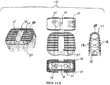
- an implant 10 that has a non-resorbable structural framework 20 and a resorbable component/material 50 embedded within framework 20.
- Framework 20 provides structural support for implant 10, while resorbable material 50 encourages or allows for bone formation and fusion for adjacent vertebral bodies contacting implant 10.
- Framework 20 is shown in detail in Figs. 2A-E .
- Framework 20 includes top and bottom bone-contacting surfaces 22, 24, proximal and distal ends 40, 42, and teeth 26 formed on top and bottom surfaces 22, 24.
- framework 20 is formed through an additive manufacturing process, such as selective laser melting (SLM), selective laser sintering (SLS), 3D printing, or any other additive process.
- SLM selective laser melting
- SLS selective laser sintering
- 3D printing 3D printing
- framework 20 is created to include a network of struts 28 that define a variety of differently-shaped geometric openings 30.
- the body of framework 20 may be successively composed layer-by-layer through an additive process, as detailed above, so that struts 28 are formed to define the different geometric openings 30 of framework 20.
- geometric openings 30 are present along the sides of framework 20, at proximal and distal ends 40, 42, and along a series of support columns 32 of framework 20.
- geometric openings 30 can provide access to and throughout an interior of framework 20 so that bone growth can occur into framework 20, as described in more detail below.
- Support columns 32 of framework 20 each include various struts 28 defining geometric openings 30, which act to provide structural support for framework 20.
- framework 20 is designed to bear a substantial portion (e.g., fifty percent (50%) or more) of the anticipated post-surgical load for implant 10.
- Support columns 32 also each include portions of top and bottom bone-contacting surfaces 22, 24 of framework 20, which have teeth 26. Struts 28 support such portions of top and bottom bone-contacting surfaces 22, 24.
- Support columns 32 also define vertical openings 34 in framework 32, which may provide areas for resorbable material 50 to extend between.
- framework 20 also includes an opening 36 (optionally threaded) at its proximal end 40 for attachment with an implantation tool (not shown), as well as a bulleted nose 84 at its distal end 42 to ease implantation of implant 10 into a disc space between adjacent vertebral bodies.
- framework 20 is composed of titanium or titanium alloy (porous or solid), tantalum, stainless steel, polyetheretherketone (PEEK), polyetherketoneketone (PEKK), or a material developed by the Applicant, which is referred to as Cortoss®. Combinations of the foregoing materials may also be used.
- Non-resorbable framework 20 can also incorporate osteoconductive materials, resorbable coatings, or resorbable materials within voids or pores of the non-resorbable material to make framework 20 an active participant in the fusion process.
- framework 20 may be constructed of solid and porous portions, as described in Applicant's U.S. Patent Application Ser. No. 62/103,276, filed January 14, 2015 , now U.S.
- the teeth of certain implants can be formed from porous and solid structures. Such teeth could be incorporated into framework 20, or used with any other implant described in more detail below. Additionally, the '276 Application describes other implant structures with porous and solid features, and it is contemplated that such technology may be used with framework 20, or any other framework or implant discussed more fully below.
- top and bottom surfaces 22, 24 of framework 20 are also tapered towards one another by a degree sufficient to accommodate the natural lordosis that may exist between the adjacent vertebral bodies.
- Such lordosis exists, for example, between adjacent vertebral bodies in the lumbar spine.
- Other embodiments, however, may include parallel top and bottom surfaces 22, 24.
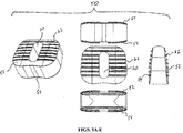
- Resorbable component/material 50 is shown in Figs. 3A-E .
- resorbable material 50 comprises a flowable/curable material that is embedded within and/or around framework 20.
- Resorbable material 50 may also provide structural support for implant 10 by defining top and bottom surfaces 52, 54 that are arranged to contact adjacent vertebral bodies, in addition to top and bottom surfaces 22, 24 of framework 20, and support the vertebral bodies once implant 10 is implanted.
- top and bottom surfaces 52, 54 include teeth 62 for digging into the vertebral bodies.
- top and bottom surfaces 52, 54 are also tapered towards one another by a degree sufficient to accommodate the natural lordosis that may exist between the adjacent vertebral bodies, but can also be arranged parallel.
- Resorbable material/component 50 also includes a single vertical opening 60 that, when combined with framework 20, provides a vertical opening 60 in implant 10.
- Vertical opening 60 may receive, for example, a bone graft material to further enhance the resorptive characteristics of implant 10 and promote fusion.
- resorbable material 50 is composed of bioactive glass, bone, polylactides, collagen, magnesium alloy, or a Cross-Linked Microstructure (CLM) bioglass material developed by Bio2 Technologies, Inc. as described, for instance, in Bio2 Technologies' U.S. Patent No. 8,673,016 , which is hereby incorporated by reference herein. Combinations of the foregoing materials may also be used.
- Resorbable material 50 may include one of the materials above in a collagen or other polymeric carrier to facilitate molding into framework 20.
- a template manufacturing process may also be used in which calcium phosphate, sol-gel derived bioactive glass, or another ceramic is produced on a porous template which occupies the openings within framework 20, and is then sacrificed by heat treatment so that only the ceramic is left behind.
- framework 20 It may also be desirable to fill framework 20 with a powder, particulate, or fiber form of resorbable material 50 in a mold and then further process by heat, chemical cross-linking or other means to bond or sinter the powder, particulate, or fibers into a solid or porous final state which fills framework 20.
- resorbable material 50 may comprise a majority of the overall material volume of implant 10, for example fifty percent (50%) or more of the overall volume. Resorbable material 50 may be embedded within struts 28.
- resorbable material 50 is described above as providing structural support for implant 10, in an alternate embodiment resorbable material is non-structural depending upon the intended implementation for implant 10.
- a non-structural resorbable component 50 may be useful for applications in which loading is expected to be predictable or additional resistance to subsidence into bone is not required.
- a structural resorbable component 50 may be required to add surface area to reduce local contact pressure where implant 10 contacts bone for configurations in which structural framework 20 is not adequate to prevent subsidence or other failure of the bone, despite framework 20 having the necessary strength to withstand the service load. In either case, the combination of resorbable component 50 and framework 20 results in a greater fusion mass than what a traditional PEEK or titanium cage would allow, as a majority of implant 10's volume becomes resorbed and replaced by bone.
- non-resorbable framework 20 may be composed of a radiopaque material, and the particular arrangement of framework 20 may optimize visualization of the resulting fusion mass within or around the implant.
- framework 20, in particular struts 28 thereof define geometric openings 30 of roughly a diamond shape within an otherwise radiopaque structure, which allows for viewing the resulting fusion mass using standard imaging techniques from a lateral perspective.
- the minimal amount of radiopaque material in this area, as well as the extent of geometric openings 30, provide direct visualization of resorbable component 50 under visualization.
- the fusion mass would be occluded from a lateral perspective due to the presence of a radiopaque structure(s) blocking visualization of the mass.
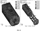
- Fig. 7 shows a Finite Element Analysis of framework 20 demonstrating the post-operative loads that framework 20 can withstand.
- the Finite Element Analysis illustrates a load of 10,000 Newtons being applied to framework 20, and the subsequent stresses seen in framework 20. As illustrated, framework 20 can withstand the 10,000 Newton load (or greater) without yielding. A load of 10,000 N was selected as it is representative of a typical dynamic service load.
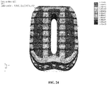
- Fig. 25 shows another Finite Element Analysis of framework 20 (without resorbable component 50) in which the scale of the Finite Element Analysis is different than in Fig. 7 .
- the scale is set to one-hundred and sixty megapascals (160 MPa), as that is the typical failure point for bone.
- the Finite Element Analysis of Fig. 25 illustrates the stresses created on framework 20 upon application of 10,000 N load, within a scale of one-hundred and sixty megapascals (160 MPa), to thereby illustrate where bone failure might occur anywhere along framework 20.
- certain areas of framework 20, illustrated in red approach or exceed stresses of 160 MPa when a 10,000 N load is applied.
- resorbable component 50 acts to distribute loads across the extent of implant 10 and thereby reduce the risk of subsidence. As shown, no areas on the top of implant 10 approach or exceed 160 MPa (the failure point for bone). Instead, maximum stresses across implant 10 appear to be on the order of about 60-80 MPa, and in an embodiment are 75 MPa. For the Finite Element Analyses of Figs.
- framework 20 was constructed as a scaffold of Ti6A14V, having a Young's Modulus of about 104,800 MPa and Poison's Ratio of 0.3, while resorbable component was composed of a biologic material having a Young's Modulus of 4.1 GPa and Poison's Ratio of 0.25.
- the surface area of non-resorbable framework 20 may be about fifty percent (50%) of the surface area of the entire implant 10, while the surface area of resorbable component 50 may also be about fifty percent (50%).
- the overall volume occupied by framework 20 may be about thirty percent (30%) of the volume of implant 10, while the overall volume of resorbable component 50 may be about seventy percent (70%).
- the 50%/50% surface area ratio results in a 68% reduction in the peak stress that the device imparts to the vertebral body endplate when a 10,000 N load is applied, which results in a stress (75 MPa) safely below the yield strength of bone (160 MPa).
- the resulting stress to the vertebral endplate caused by framework 20 is about 237 MPa, which is well above the yield strength of bone and would be likely to result in unwanted subsidence of framework 20.
- the particular combination of framework 20 and resorbable component 50 acts to decrease subsidence of implant 10 and encourage or allow bone formation and fusion to occur.
- Implant 10 may be implanted into a disc space between adjacent vertebral bodies or as part of a corpectomy procedure in the same fashion as a traditional interbody device (IBD) or vertebral body replacement (VBR), respectively.
- Implant 10 allows for fusion to occur as resorbable material 50 is resorbed and replaced by newly-formed bone.
- Non-resorbable framework 20 acts as a structural scaffold or as a framework for resorbable material 50 to interface with.
- the non-resorbable framework 20 that contacts the vertebral end plates can also act to help the fusion process by, for example, being osteoconductive and/or incorporating resorbable coatings or resorbable materials within voids or pores of the non-resorbable material, etc., as described above.
- the particular configuration of resorbable and non-resorbable material in implant 10 therefore efficiently achieves fusion and bone formation, while providing ample structural support for adjacent vertebral bodies.
- a particular manufacturing technique may also be used to construct implant 10 of Figs. 1A-E (or any of the other implants, discussed below).
- polycaprolactone PCL
- GAA Glacial Acetic Acid
- Bioactive glass is then added to the PCL-GAA solution under light agitation to prevent settling.
- the solution is loaded into a syringe and extruded into a mold containing framework 20.
- the filled mold is then injected with water and/or completely submerged in a water bath to precipitate the plastic onto the device. Once all of the PCL has precipitated, the filled implant 10 is removed from the mold.
- an alternate implant 110 is shown that is similar to implant 10. Due to the similarities between implants 10, 110, like numerals (within the 100-series of numbers) refer to like elements in this embodiment and predominantly the differences between the embodiments will be discussed herein.
- Implant 110 includes a structural, non-resorbable framework 120 and a resorbable component/material 150 positioned within and/or around framework 120.
- framework 120 is similar to framework 20 of implant 10, except that it includes left 137, center 138, and right 139 sections and a keyed opening 144 between the sections. Keyed openings 144 are formed along top and bottom surfaces 122, 124 and extend from proximal end 140 to distal end 142 of framework 120.
- a first keyed opening 144 is positioned along top surface 122 between left 137 and center 138 sections
- a second keyed opening 144 is positioned along top surface 122 between center 138 and right 139 sections
- a third keyed opening 144 is positioned along bottom surface 124 between left 137 and center 138 sections
- a fourth keyed opening 144 is positioned along bottom surface 124 between center 138 and right 139 sections.
- a total of four (4) keyed openings 144 may be present in an embodiment.
- Keyed openings 144 are shaped and arranged to receive a variety of arrow-shaped bone anchors as disclosed, for example, in Applicant's U.S. Patent No. 8,349,015 , which is hereby incorporated by reference herein.
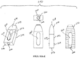
- An example of an arrow-shaped bone anchor is shown in Figs. 4A-E as anchor 174.
- An anchor very similar to anchor 174 is shown and described in connection with Figs. 6A-B of the '015 Patent, and it is expressly contemplated that anchor 174 may include any of the features of the anchor of Figs. 6A-B of the '015 Patent, or any other anchor disclosed in the '015 Patent.
- anchor 174 can include an interconnection portion 176 extending from an anchor portion 178 for engaging with keyed openings 144.
- Interconnection portion 176 may be dovetail-shaped in an embodiment to engage with a dovetail-shaped opening 144 in framework 120.
- anchor 174 may have a stop feature at its trailing end to ensure that anchor 174 does not travel too far into framework 120.
- Anchor 174 may also have lock features for locking anchor 174 into engagement with framework 120 once fully inserted.
- anchor 174 can include any of the features of any of the anchors of the '015 Patent, and engage and be retained in framework 120 by the means described in the '015 Patent.
- Anchor 174 can therefore provide an efficient means of securing implant 110 to adjacent vertebral bodies once implanted.
- anchors 174 may be arranged to diverge and angle away from one another along top and bottom surfaces 122, 124 of framework 120, and thus implant 110.
- any of the directional and/or angled configurations of anchors disclosed in the '015 Patent could equally be used with framework 120, and thus implant 110.
- Framework 120 also differs from framework 20 in that it is substantially devoid of struts and geometric openings, as present in framework 20. Instead, vertical openings 134 are defined in top and bottom surfaces 122, 124 of left 137, center 138, and right 139 sections of framework 120, and lateral openings 148 are present as well. Further, framework 120 may be open between each support column 132 within the main body of framework 120.
- Resorbable component 150 is shown in detail in Figs. 6A-E . As resorbable component 150 is somewhat similar to resorbable component 50, like numerals refer to like elements in this embodiment and predominantly the differences between components 50, 150 will be discussed herein.
- Resorbable component 150 includes left 168, center 170, and right 172 sections to match left 137, center 138, and right 139 sections of framework 120.
- Resorbable component 150 may be composed of a flowable material that is positioned within and/or around framework 120 during, for example, manufacturing. Alternatively, it may be possible to pre-construct resorbable component 150 and slide it into engagement with framework 120 through an opening in framework 120 ( e.g., one of lateral openings 148).
- Each of left 168, center 170, and right 172 sections of resorbable component 150 include a vertical opening 160 that is alignable with vertical openings 134 of framework 120.
- vertical openings 160 of resorbable component 150 define openings in implant 110 that, in an embodiment, are sized to receive bone-graft material ( e.g., for promoting fusion).
- Resorbable component 150 also includes its own keyed openings 166 for aligning with keyed openings 144 of framework 120 and providing an interconnection mechanism between implant 110 and anchors 174.
- a first keyed opening 166 is positioned along top surface 152 of resorbable component 150 between left 168 and center 170 sections
- a second keyed opening 166 is positioned along top surface 152 between center 170 and right 172 sections
- a third keyed opening 166 is positioned along bottom surface 154 of resorbable component 150 between left 168 and center 170 sections
- a fourth keyed opening 166 is positioned along bottom surface 154 between center 170 and right 172 sections.
- Keyed openings 166 may be of any shape, have any direction and/or angle, and include any of the features of such similar keyed openings as described in the '015 Patent, incorporated by reference above. Thus, keyed openings 166 engage with anchors 174 once resorbable component 150 is positioned within and/or around framework 120.
- Resorbable component 150 may also include engagement structures 164, for example in the form of cutouts, arranged to engage with like engagement structures (not shown) in framework 120. Such engagement structures 164 secure resorbable component 150 to framework 120.
- Resorbable component 150 also includes an opening 180 for connection with an insertion tool that is alignable with like opening 136 in framework 120. Openings 136, 180 are, in an embodiment, threaded for engagement with a threaded portion of an implantation tool.
- framework 120 and/or resorbable component 150 are not discussed above, for example teeth 126, 162 thereon, it is to be understood that such structures are encompassed in framework 120 and/or resorbable component 150 and are referenced in the figures by way of reference numerals that correspond or are like the reference numerals for framework 20 and resorbable component 50 of implant 10. Additionally, it is to be understood that any of the materials disclosed for framework 20 and resorbable component 50 may be used to compose framework 120 and resorbable component 150, and that resorbable component can be used as a structural member in an embodiment or a non-structural member in other embodiments.
- resorbable component 150 When used as a structural member, resorbable component 150 can act to assist with preventing or mitigating subsidence of framework 120 into adjacent vertebral bodies, a common downfall of current PEEK and/or titanium cages. Further, the surface area and volume percentages and ratios discussed above in connection with implant 10 can also be used with implant 110.
- implants 10, 110 include but are not limited to: (1) the addition of a resorbable component 50, 150 that may, at least initially, act to distribute contact loads with bone in order to prevent failure of the bone due to high localized stresses (subsidence is a known potential failure mode of existing IBDs); (2) a particular balance of resorbable and non-resorbable structures that both meets overall implant structural requirements and results in minimizing the volume, location, and orientation of radiopaque non-resorbable structures to facilitate the use of radiographic imaging techniques to assess local anatomy and progress of a fusion mass; and/or (3) a combination of resorbable and non-resorbable regions able to interface with additional fixation elements in such a manner that fixation between the IBD and bone is not lost as material resorbs.
- Other benefits of implants 10, 110 are clearly also experienced.
- Implant 210 includes a substantially non-structural, non-resorbable frame 220 used in connection with a structural, resorbable component 250 positioned within frame 220.
- certain like reference numerals refer to like elements but, due to the difference between implant 210 and implants 10, 110, no consistent numbering scheme is used.
- Frame 220 as shown in Figs. 9A-E , includes top and bottom bone-contacting surfaces 222, 224 that, in an embodiment, are formed of a porous but non-resorbable material.
- Top and bottom surfaces 222, 224 may be very thin in some instances ( e.g., two millimeters (2 mm) or less), and thus, top and bottom surfaces 222, 224 alone are non-structural due to their thinness.
- implant 210 when combined with structural resorbable component 250, implant 210 is able to meet the demands of the post-surgical loads that are typically experienced while also encouraging fusion and resorption.
- Frame 220 also includes proximal and distal ends 240, 242 and an opening 236 for connection with an implantation tool (not shown) at proximal end 240. Opening 236 is threaded in an embodiment to engage with a threaded portion of an implantation tool (not shown).
- Frame 220 has a bulleted nose 238 at its distal end 242, and a vertical opening 226 through frame 220's top and bottom surfaces 222, 224.
- Frame 220 also includes a large lateral opening 228 sized to receive resorbable component 250, as described below.
- An opposing lateral side of frame 220 is closed, as shown in cross section in Fig. 9E .
- Figs. 10A-E show resorbable component 250 in various views.
- Resorbable component 250 may form a structural component for implant 210 and be composed of structural resorbable material. Any of the resorbable materials described in connection with implants 10, 110 can be used for resorbable component 250. Likewise, any of the materials and/or methods used to compose frameworks 20, 120 of implants 10, 110 can be used to construct frame 220 of implant 210.
- Resorbable component 250 of Figs. 10A-E includes top and bottom surfaces 252, 254, proximal and distal ends 256, 258, an implantation tool opening 266 in proximal end 256, and a bulleted nose 270 at distal end 258.
- a vertical opening 260 is also formed in resorbable component 250 through top and bottom surfaces 252, 254.
- tool opening 266 is threaded for engagement with a threaded portion of an implantation tool (not shown).
- opening 266 may extend into the body of resorbable component 250 and open out into vertical opening 260, such that opening 266 may form an injection port for injection of a fusion material into the body of resorbable component 250.
- bone graft material may be injected into the body of resorbable component 250 through opening 266 so that such bone graft material is able to interface with adjacent vertebral bodies through vertical opening 260 and affect fusion.
- Resorbable component 250 also has engagement structures 264 that project outward from vertical opening 260. Engagement structures 264 may interface with like engagement structures (not shown) on frame 220 to secure resorbable component 250 relative to frame 220.
- resorbable component 250 may be slid into engagement with frame 220 through its lateral opening 228 so that engagement structures 264 of resorbable component 250 engage with like engagement structures (not shown) on frame 220 to secure resorbable component 250 relative to frame 220.
- these components could be pre-assembled by other means such as molding, packing, thermal assembly, 3D printing, or interference fit.
- resorbable component 250 in frame 220 it can provide structural support for implant 210 and reinforce frame 220 (in particular frame 220's top and bottom bone-contacting surfaces 222, 224).
- opening 266 in resorbable component 250 and opening 236 in frame 220 can be used as injection ports to inject a fusion material (e.g., bone graft) into resorbable component 250 for assisting with the fusion process.
- a fusion material e.g., bone graft
- openings 236, 266 align once resorbable component 250 is positioned in frame 220, such openings 236, 266 may act as an injection port in the above-described manner.
- the implantation tool (not shown) used to connect with openings 236, 266 and insert implant 210 into the intervertebral space may also have an injection conduit for injecting fusion material into resorbable component 250.
- the implantation tool could threadably connect with at least one of openings 236, 266 and serve to also injection fusion material into resorbable component 250 through its injection conduit.
- top and bottom surfaces 222, 224 of frame 220 and top and bottom surfaces 252, 254 of resorbable component 250 may be tapered towards one another to create a lordotic implant 210 for use in certain applications (e.g., in the lumbar spine where natural lordosis is present).
- Implant 210 due to the thin top and bottom surfaces 222, 224 of frame 220 and the structural support provided by resorbable component 250, may also act to increase graft loading over time. As an example, as resorbable component 250 resorbs and new bone is formed, the structural stiffness of implant 210 may be reduced. In this case, where a bone graft is used with implant 210 ( e.g., in vertical opening 260 of resorbable component 250 or elsewhere), such a decrease in stiffness can lead to increased graft loading over time and improve the fusion process.
- non-resorbable frame 220 may be composed of a titanium alloy and resorbable component 250 of a resorbable material with mechanical properties similar to bone, such as CLM.
- non-resorbable frame 220 may occupy one-hundred percent (100%) of the overall surface area in contact with the vertebral endplates, while resorbable component 250 may occupy zero percent (0%). In this instance, the pores of non-resorbable frame 220 are not filled with a resorbable material.
- the volume of frame 220 may be thirty six percent (36%) of the overall volume of implant 210, while the volume of resorbable component 250 may be sixty four percent (64%).
- a benefit of this volume ratio is that the overall stiffness of the device is primarily dictated by resorbable component 250, which makes up a majority of the volume and also bears a majority of the service load in the cephalad/caudad direction.
- Another benefit of this configuration, as it relates to implant 210, is that the radiopaque material (frame 220) has been located such that there is no obstruction for imaging the fusion mass from a lateral direction.
- Implant 310 comprises a non-resorbable, non-structural framework 320 that has a fluid channel conduit(s) 324 and a structural, resorbable component 350 positioned around framework 320. Due to the differences from previous embodiments, certain like numerals refer to like elements, but no consistent numbering scale is used in this embodiment.
- framework 320 of implant 310 has a main body 322 that includes at least one conduit 324 therein.
- Framework 320 also has proximal and distal ends 330, 332, an injection port 334 at proximal end 330, and a vertical opening 336 through main body 322.
- Injection port 334 doubles as an implantation tool opening, and thus, it is threaded in an embodiment to engage with a threaded portion of an implantation tool (not shown).
- Injection port 334 is fluidly connected to conduit 324 so that fluid can be injected into port 334 and travel into and through conduit 324.
- conduit 324 traverses substantially an entire perimeter of main body 322 of framework 320.
- Framework 320 also includes an enlarged portion 340 forming a step at its proximal end 330 and conduit 324 may traverse enlarged portion 340 until it intersects with and opens out into injection port 334.
- main body 322 is closed beyond injection port 334 so that, as fluid is forced into injection port 334, it flows from port 334 and into conduit 324.
- injection port 334 and conduit 324 can include any of the fittings and/or flow channels described in connection with Applicant's U.S. Application Ser. No. 62/103,270 , now U.S. Patent App. No. 14/994,697 , which are hereby incorporated by reference herein.
- the '270 Application was attached as Exhibit B to the '146 Provisional.
- Figs. 5A-E of the '270 Application depict an implant 410 with a threaded passage 424 and a flow channel 428 in fluid communication therewith.
- the structure of threaded passage 424 and flow channel 428 could be utilized in connection with framework 320 herein.
- any of the flow channels (including multiple flow channels), fittings, passages therefor, and other structures of the implants taught in the '270 Applicant can be used with framework 320 and/or resorbable component 350 herein.
- Applicant provides certain examples of the structures from the '270 Application that could be used herein, but such examples are not to be taken as limiting and it should be recognized that any of the principles of the '270 Application are usable with implant 310.
- Framework 320 of implant 310 also has a plurality of cylinders 326 projecting outward from main body 322, which terminate in holes 327.
- cylinders 326 extend through resorbable component 350 so that holes 327 are open to the exterior of implant 310, much like the holes described in the '270 Application.
- cylinders 326 each have a conduit 338 that is in fluid communication with conduit 324 of main body 322.
- fluid can flow from conduit 324, into each of conduits 338 of cylinders 326, and ultimately to the exterior of implant 310 via holes 327.
- the fluid injected into implant 310 may be a biologic material, a therapeutic material, a bone cement, bone-growth promoting material, Bone Marrow Aspirate, antimicrobial material, bone morphogenic proteins ("BMP"), stem cells, solutions to assist in the resorption process, tissue-targeted glycosaminoglycans, or any other like material.
- Resorbable component 350 includes top and bottom surfaces 352, 354, proximal and distal ends 356, 358, a vertical opening 360, and teeth 362 formed on top surface 352.
- Resorbable component 350 may be composed of any of the resorbable materials discussed in connection with the previous implants 10, 110, 210 and, in an embodiment, is a flowable material that is embedded within framework 320 during manufacturing.
- framework 320 and its projecting cylinders 326 can act as a scaffold to retain resorbable component 350 in connection with framework 320.
- framework 320 in its capacity as a scaffold, can provide support to resorbable component 350 so that component 350 does not crack or fracture during implantation.
- resorbable materials are, in some existing implants, susceptible to fracture or cracking during implantation. As an example, allograft bone is often brittle during implantation.
- Resorbable component 350 also has a series of holes 368 arranged to align with projecting cylinders 326 of framework 320 and allow fluid to exit holes 327 of such cylinders 326. Fluid exiting holes 327 of cylinders 326 (and thus holes 368 of resorbable component 350) may act to coat top surface 352 of resorbable component 350 and assist with the resorption and/or fusion process.
- Resorbable component 350 further includes, at its proximal end 356, a stepped portion 364 shaped and arranged to engage with enlarged portion 340 of framework 320.
- a second resorbable component 350 identical to that shown in Figs. 13A-E is usable with implant 310 on an opposing side of implant 310.
- conduit 324 of framework 320 may, in addition to or as a substitute to directing fluid to an exterior of implant 310, also be arranged to direct fluid to a location fully enclosed within resorbable component 350. Such a conduit would be beneficial to deliver fluid (e.g., a resorptive-enhancing fluid) to a location within resorbable component 350. It is also the case that conduit 324 (or multiple conduits if included) may direct fluid to other exterior parts of implant 310, for example the sides or proximal and/or distal ends of implant 310. In addition, if multiple conduits 324 are included with framework 320, different materials can be directed to different portions of implant 310. These types of conduits are disclosed in more detail in the '270 Application.
- Implant 410 includes a non-structural, non-resorbable framework 420 and a structural, resorbable component 450 positioned within and/or around framework 420. Due to the differences from previous embodiments, certain like numerals refer to like elements, but no consistent numbering scale is used in this embodiment.
- framework 420 has first and second ring members 422, 424 and struts 426 that connect ring members 422, 424. Struts 426 terminate in proximal and distal end plates 428, 430 arranged on framework 420.
- proximal end plate 428 includes an implantation tool opening 432 that is optionally threaded for engagement with a threaded portion of an implantation tool (not shown).
- Framework 420 via its ring members 422, 424, struts 426, and end plates 428, 430, provides a scaffold for embedding resorbable component 450 within framework 420.
- framework 420 is non-structural, in the sense that it does not support post-surgical loads directly, it provides strength and rigidity to implant 410 and resorbable component 450 thereof.
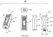
- Resorbable component 450 is shown in Figs. 16A-E and includes a main body 451 having top and bottom bone-contacting surfaces 452, 454, proximal and distal ends 456, 458, an implantation tool opening 466 at proximal end 456, and a vertical opening 460 formed through main body 451.
- implantation tool opening 466 may or may not be threaded for engagement with a threaded portion of an implantation tool (not shown).
- opening 466 may be in fluid communication with vertical opening 460 so that a fusion or another biologic material can be injected into opening 460 via a tool.
- Such a tool is disclosed, for example, in the '270 Application and it is expressly contemplated that any tool of the '270 Application is usable with implant 410, as well as any of the previous implants.
- Resorbable component 450 also includes teeth 462 on its top and bottom surfaces 452, 454, and may be composed of any of the resorbable materials hereinbefore described.
- resorbable component 450 is preassembled on framework 420 at the point of manufacture and provides structural support for implant 410 in that it is capable of supporting the post-surgical loads borne on implant 410 after insertion into a patient.
- This type of implant configuration is particularly useful when the resorbable material is strong but brittle, as spinal implants are often impacted into place and must be able to withstand impact loads without fracturing or becoming damaged.
- framework 450 it is possible to modify framework 450 to also increase or decrease the overall stiffness of implant 410.
- the components of framework 420 may be made thicker or thinner in certain locations (e.g., struts 426 and rings 422, 424) to increase or decrease the overall rigidity of framework 420, and thus implant 410.
- Different thickness frameworks 420, and Finite Element Analyses related thereto, are shown in Figs. 17-18 . As reflected in those figures, a different stiffness is realized for implant 410 between the thicker and thinner frameworks 420.
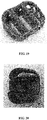
- Figs. 19-23 depict various images of prototypes of frameworks 20, 120, 220, 320, 420 of implants 10, 110, 210, 310, 410. It is to be understood that any of these prototypes can be constructed using an additive manufacturing process, as hereinbefore disclosed. Additionally, each of the frameworks may be composed of any of the materials discussed in connection with any of the above-described frameworks. Further, other manufacturing methods such as injection molding processes may be used to construct frameworks 20, 120, 220, 320, 420. Thus, a variety of materials and manufacturing methods may be utilized to create frameworks 20, 120, 220, 320, 420. Certain particular features of the various prototypes will now be discussed.
- a porous and/or roughened layer or surface coating may be used on all, substantially all, or a majority of the exposed surfaces of frameworks 20, 120, 220, 320, 420.
- Such a coating could enhance the resorptive and/or fusion characteristics of a particular framework, make it more amenable to connection with a particular resorbable component or material, or simply increase the framework's resistance to migration in the intervertebral space once implanted.
- top and bottom bone-contacting surfaces 222, 224 are highly porous and thin. Such surfaces 222, 224, as described above, are structurally supported by resorbable component 250. Additionally, in the image of the prototype of framework 220, it is shown that framework 220 can have multiple lateral openings for receiving resorbable component 250, instead of only a single lateral opening 228.
- struts may be used in framework 420.
- smaller struts may traverse between distal end plate 430 and second ring 424 and between proximal end plate 428 and first ring 422.
- One or more side struts may also be used on framework 420, as shown. Such side struts may be bowed and be connected to proximal end plate 428, first ring 422, second ring 424, and finally distal end plate 430.
- These additional struts may provide yet additional stiffness to implant 410 and/or act as a further scaffold for resorbable component 450.
- a surgical kit is also contemplated within the present invention. Due to the inability for many of the known resorbable materials to be properly sterilized via autoclave without being rendered unusable, it is expected that at least any of the resorbable components described above may be provided in a sterile package in the kit. This packaging could enclose either the entire finished implant (resorbable and non-resorbable components), or just the resorbable component with the intent to assemble intraoperatively. Indeed, although many of the implants discussed above are described as being assembled upon manufacturing, it is contemplated that resorbable and non-resorbable components of the above implants may be assembled in the operating room or in-situ.
- the in-situ assembly process could include first implanting the non-resorbable component into the spine, and then injecting or flowing a curable resorbable component through and/or around the non-resorbable portion/framework within the disc space.
- the resorbable component could then be allowed to cure/harden, at which point the implant may be left implanted for purposes of resorption of the resorbable material and fusion of the vertebral bodies. It is contemplated that such a process is possible with any of frameworks 20, 120, 220, 320, 420 of implants 10, 110, 210, 310, 410.
- the surgical kit may also include implants 10, 110, 210, 310, 410 of different sizes for use with different patients, and tools for the implantation of such implants.
- An example of such a tool is the tool disclosed in the '270 Application, which is usable to insert some of the implants described previously and/or inject a biologic material into such implants.
- implants 10, 110, 210, 310, 410 are not limited to any particular surgical approach or use, it is contemplated that certain of the above implants may be more particularly suited for certain surgical applications.
- implants 10, 110 may be suited for use as ALIF implants (anterior lumbar interbody fusion)
- implant 210 may be suited for use as a PLIF implant (posterior lumbar interbody fusion)
- implants 310, 410 may be suited for use as DLIF implants (direct lateral interbody fusion).
- the foregoing implants may be suitable for use in other areas of the spine and along different surgical approaches ( e.g., anterolateral, transforaminal, etc.).
- the features and structures of the above implants may be suitable for use in cervical applications.
- the above-described uses and surgical approaches are therefore not to be taken as limiting and are merely exemplary.
- the implants shown in the figures are merely examples of those which can be created according to the present invention. It is contemplated that other implant shapes/configurations can be made in accordance with the present invention.
- implants 10, 110, 210, 310, 410 are also contemplated.
- implants 10, 110, 210, 310, 410 may not be described above as including lordotic bone-contacting surfaces, such a feature is expressly contemplated with each of implants 10, 110, 210, 310, 410 as an option.
- any of implants 10, 110, 210, 310, 410 may include lordotic surfaces (e.g., surfaces that taper towards one another) to accommodate natural lordosis that is present in certain areas of the spine.
- lordotic surfaces e.g., surfaces that taper towards one another
- Some of implants 10, 110, 210, 310, 410 are shown in the figures with a lordotic taper, although that feature may not be expressly discussed above.
- implant 310 may include multiple fluid conduits instead of the single conduit 324 shown in the figures. Such conduits may be fluidly isolated from one another to allow different fluids to be transferred to different parts of the implant, or the conduits may be fluidly connected. Additionally, certain fluid conduits may lead to areas wholly encompassed in resorbable component 350 instead of opening out to an exterior of implant 310, as described above.
- framework 120 and resorbable component 150 may be provided with more traditional bone-anchor features.
- framework 120 and resorbable component 150 may be provided with threaded holes for engaging with traditional threaded bone screws.
- Such holes may be arranged substantially as shown in connection with keyed openings 144, 166 ( e.g., the holes may number four (4) in total, and diverge outward so that bone screws are directed up/down into the vertebral bodies, and in an outward direction). If bone-screw holes are included, certain anti-backout features might also be provided.
- a movable protrusion may be provided in each hole that automatically moves in response to a bone screw being inserted into the hole, and snaps back once the bone screw has passed the protrusion so as to cover the particular bone screw.
- Such a mechanism could prevent backout of screws inserted into implant 110.
- Other anti-backout mechanisms might also be used, such as traditional "manhole covers,” which are attached to the implant after the bone screws have been inserted and act to cover one or more of the bone screws.
- any of implants 10, 110, 210, 310, 410 may utilize the following surface area and/or volume ranges for the non-resorbable and resorbable components thereof: Surface Area in Contact with Endplates Volume Minimum Maximum Minimum Maximum Non-resorbable 10% 100% 10% 80% Resorbable 0% 90% 20% 90%
- any of the resorbable components above may be combined with biologics and/or anti-infectives, including but not limited to bone marrow, blood, growth factors, proteins, peptides CAGs, antimicrobials, and/or antibiotics.
- biologics and/or anti-infectives including but not limited to bone marrow, blood, growth factors, proteins, peptides CAGs, antimicrobials, and/or antibiotics.
Landscapes
- Health & Medical Sciences (AREA)
- Engineering & Computer Science (AREA)
- Biomedical Technology (AREA)
- Orthopedic Medicine & Surgery (AREA)
- Neurology (AREA)
- General Health & Medical Sciences (AREA)
- Oral & Maxillofacial Surgery (AREA)
- Transplantation (AREA)
- Veterinary Medicine (AREA)
- Public Health (AREA)
- Life Sciences & Earth Sciences (AREA)
- Animal Behavior & Ethology (AREA)
- Cardiology (AREA)
- Vascular Medicine (AREA)
- Heart & Thoracic Surgery (AREA)
- Chemical & Material Sciences (AREA)
- Dermatology (AREA)
- Medicinal Chemistry (AREA)
- Epidemiology (AREA)
- Prostheses (AREA)
Applications Claiming Priority (1)
| Application Number | Priority Date | Filing Date | Title |
|---|---|---|---|
| US201562163146P | 2015-05-18 | 2015-05-18 |
Publications (2)
| Publication Number | Publication Date |
|---|---|
| EP3095417A1 true EP3095417A1 (de) | 2016-11-23 |
| EP3095417B1 EP3095417B1 (de) | 2025-04-09 |
Family
ID=56014886
Family Applications (1)
| Application Number | Title | Priority Date | Filing Date |
|---|---|---|---|
| EP16170075.2A Active EP3095417B1 (de) | 2015-05-18 | 2016-05-18 | Teilweise resorbierbare implantate |
Country Status (5)
| Country | Link |
|---|---|
| US (4) | US10537666B2 (de) |
| EP (1) | EP3095417B1 (de) |
| JP (1) | JP2016214866A (de) |
| AU (1) | AU2016203218B2 (de) |
| CA (1) | CA2930123A1 (de) |
Families Citing this family (56)
| Publication number | Priority date | Publication date | Assignee | Title |
|---|---|---|---|---|
| US10687956B2 (en) | 2014-06-17 | 2020-06-23 | Titan Spine, Inc. | Corpectomy implants with roughened bioactive lateral surfaces |
| JP2017537746A (ja) * | 2014-12-16 | 2017-12-21 | セラムテック ゲゼルシャフト ミット ベシュレンクテル ハフツングCeramTec GmbH | 脊椎ケージおよびその挿入器具 |
| AU2016200179B2 (en) | 2015-01-14 | 2020-09-17 | Stryker European Operations Holdings Llc | Spinal implant with porous and solid surfaces |
| CA2917503A1 (en) | 2015-01-14 | 2016-07-14 | Stryker European Holdings I, Llc | Spinal implant with fluid delivery capabilities |
| EP3288501B1 (de) | 2015-04-29 | 2020-11-25 | Institute For Musculoskeletal Science And Education, Ltd. | Spulenimplantate |
| US10449051B2 (en) | 2015-04-29 | 2019-10-22 | Institute for Musculoskeletal Science and Education, Ltd. | Implant with curved bone contacting elements |
| US10492921B2 (en) * | 2015-04-29 | 2019-12-03 | Institute for Musculoskeletal Science and Education, Ltd. | Implant with arched bone contacting elements |
| US10709570B2 (en) | 2015-04-29 | 2020-07-14 | Institute for Musculoskeletal Science and Education, Ltd. | Implant with a diagonal insertion axis |
| CA2930123A1 (en) * | 2015-05-18 | 2016-11-18 | Stryker European Holdings I, Llc | Partially resorbable implants and methods |
| TWI726940B (zh) | 2015-11-20 | 2021-05-11 | 美商泰坦脊柱股份有限公司 | 積層製造整形外科植入物之方法 |
| EP3377255A1 (de) | 2015-11-20 | 2018-09-26 | Titan Spine, Inc. | Verfahren zur generativen fertigung von orthopädischen implantaten |
| JP2018537235A (ja) | 2015-12-16 | 2018-12-20 | ニューヴェイジヴ,インコーポレイテッド | 多孔質脊椎固定インプラント |
| EP3493769B1 (de) * | 2016-08-03 | 2022-03-30 | Titan Spine, Inc. | Titanimplantatoberflächen frei von alpha-case und mit verbesserter osteoinduktion |
| US10478312B2 (en) | 2016-10-25 | 2019-11-19 | Institute for Musculoskeletal Science and Education, Ltd. | Implant with protected fusion zones |
| US11033394B2 (en) | 2016-10-25 | 2021-06-15 | Institute for Musculoskeletal Science and Education, Ltd. | Implant with multi-layer bone interfacing lattice |
| US10512549B2 (en) | 2017-03-13 | 2019-12-24 | Institute for Musculoskeletal Science and Education, Ltd. | Implant with structural members arranged around a ring |
| US10357377B2 (en) | 2017-03-13 | 2019-07-23 | Institute for Musculoskeletal Science and Education, Ltd. | Implant with bone contacting elements having helical and undulating planar geometries |
| US10624746B2 (en) * | 2017-04-01 | 2020-04-21 | HD LifeSciences LLC | Fluid interface system for implants |
| KR101958952B1 (ko) * | 2017-04-13 | 2019-03-15 | 김정성 | 하중 저항력이 향상된 다공성 구조의 척추 케이지 |
| EP3459502B1 (de) | 2017-09-20 | 2024-05-22 | Stryker European Operations Holdings LLC | Wirbelsäulenimplantate |
| US10744001B2 (en) | 2017-11-21 | 2020-08-18 | Institute for Musculoskeletal Science and Education, Ltd. | Implant with improved bone contact |
| US10940015B2 (en) | 2017-11-21 | 2021-03-09 | Institute for Musculoskeletal Science and Education, Ltd. | Implant with improved flow characteristics |
| US20190167433A1 (en) * | 2017-12-04 | 2019-06-06 | Duke University | Orthopedic implant for sustained drug release |
| USD870889S1 (en) | 2018-03-02 | 2019-12-24 | Restor3D, Inc. | Cutout airway stent |
| USD870888S1 (en) | 2018-03-02 | 2019-12-24 | Restor3D, Inc. | Accordion airway stent |
| USD871577S1 (en) | 2018-03-02 | 2019-12-31 | Restor3D, Inc. | Studded airway stent |
| USD870890S1 (en) | 2018-03-02 | 2019-12-24 | Restor3D, Inc. | Spiral airway stent |
| US10183442B1 (en) | 2018-03-02 | 2019-01-22 | Additive Device, Inc. | Medical devices and methods for producing the same |
| US10744003B2 (en) | 2018-05-08 | 2020-08-18 | Globus Medical, Inc. | Intervertebral spinal implant |
| US10682238B2 (en) | 2018-05-08 | 2020-06-16 | Globus Medical, Inc. | Intervertebral spinal implant |
| US10524926B2 (en) | 2018-05-08 | 2020-01-07 | Globus Medical, Inc. | Intervertebral spinal implant |
| US11090412B2 (en) | 2018-12-21 | 2021-08-17 | Zavation Medical Products Llc | Bone repair composition and kit |
| US11039931B2 (en) | 2019-02-01 | 2021-06-22 | Globus Medical, Inc. | Intervertebral spinal implant |
| US10889053B1 (en) | 2019-03-25 | 2021-01-12 | Restor3D, Inc. | Custom surgical devices and method for manufacturing the same |
| EP3962384A1 (de) * | 2019-04-30 | 2022-03-09 | Life Spine, Inc. | Alif-wirbelsäulenimplantat mit nockenschrauben zur hemmung von knochenverankerungsaustritt |
| CN111067672A (zh) * | 2019-12-31 | 2020-04-28 | 江苏澳格姆生物科技有限公司 | 一种可降解颈椎融合器及其植入方法 |
| USD920517S1 (en) | 2020-01-08 | 2021-05-25 | Restor3D, Inc. | Osteotomy wedge |
| US10772732B1 (en) | 2020-01-08 | 2020-09-15 | Restor3D, Inc. | Sheet based triply periodic minimal surface implants for promoting osseointegration and methods for producing same |
| USD920516S1 (en) | 2020-01-08 | 2021-05-25 | Restor3D, Inc. | Osteotomy wedge |
| USD920515S1 (en) | 2020-01-08 | 2021-05-25 | Restor3D, Inc. | Spinal implant |
| CN115297907A (zh) * | 2020-02-24 | 2022-11-04 | 普罗斯蒂安公司 | 生物活性可植入装置和复合生物材料以及用于制造生物活性可植入装置和复合生物材料的方法 |
| WO2022147452A1 (en) * | 2020-12-29 | 2022-07-07 | Brigham Young University | Artificial vertebral endplates and associated methods |
| DE102021201695A1 (de) * | 2021-02-23 | 2022-08-25 | Karl Leibinger Medizintechnik Gmbh & Co. Kg | Mehrteiliges Implantat mit Stützelement und Funktionselement |
| US20230120830A1 (en) * | 2021-10-20 | 2023-04-20 | Bone Solutions, Inc. | Spinal Implant with a Magnesium-Phosphate Three-Dimensional Porosity Structure |
| US11850144B1 (en) | 2022-09-28 | 2023-12-26 | Restor3D, Inc. | Ligament docking implants and processes for making and using same |
| US11806028B1 (en) | 2022-10-04 | 2023-11-07 | Restor3D, Inc. | Surgical guides and processes for producing and using the same |
| WO2024107638A2 (en) * | 2022-11-14 | 2024-05-23 | Ohio State Innovation Foundation | Multi-material stiffness-matched implant devices and fabrication methods |
| USD1053353S1 (en) | 2023-03-24 | 2024-12-03 | Restor3D, Inc. | Orthopedic screw |
| USD1051384S1 (en) | 2023-03-24 | 2024-11-12 | Restor3D, Inc. | Bone fixation pin |
| USD1118931S1 (en) | 2023-03-31 | 2026-03-17 | Restor3D, Inc. | Orthopedic implant |
| USD1124342S1 (en) | 2023-05-10 | 2026-04-28 | Restor3D, Inc. | Talus implant |
| USD1122446S1 (en) | 2023-05-10 | 2026-04-14 | Restor3D, Inc. | Talus implant |
| USD1052732S1 (en) | 2023-05-25 | 2024-11-26 | Restor3D, Inc. | Subtalar wedge |
| US11960266B1 (en) | 2023-08-23 | 2024-04-16 | Restor3D, Inc. | Patient-specific medical devices and additive manufacturing processes for producing the same |
| US12591216B1 (en) | 2024-02-02 | 2026-03-31 | Restor3D, Inc. | Patient-specific medical devices based on bone density and processes for producing the same |
| US12605251B1 (en) | 2025-03-28 | 2026-04-21 | Restor3D, Inc. | Patient-specific shoulder implants and processes for producing and using the same |
Citations (5)
| Publication number | Priority date | Publication date | Assignee | Title |
|---|---|---|---|---|
| US5702449A (en) * | 1995-06-07 | 1997-12-30 | Danek Medical, Inc. | Reinforced porous spinal implants |
| US20100042221A1 (en) * | 2000-09-19 | 2010-02-18 | Boyd Lawrence M | Reinforced molded implant formed of cortical bone |
| US20100076559A1 (en) * | 2007-05-04 | 2010-03-25 | Titan Spine, Llc | Composite telescoping anterior interbody spinal implant |
| US20120277876A1 (en) * | 2005-05-06 | 2012-11-01 | Titan Spine, Llc | Spinal implant having a passage for enhancing contact between bone graft material and cortical endplate bone |
| US20140121776A1 (en) * | 2012-09-25 | 2014-05-01 | 4Web, Inc. | Programmable implants and methods of using programmable implants to repair bone structures |
Family Cites Families (375)
| Publication number | Priority date | Publication date | Assignee | Title |
|---|---|---|---|---|
| US3486505A (en) | 1967-05-22 | 1969-12-30 | Gordon M Morrison | Orthopedic surgical instrument |
| US3641590A (en) | 1970-01-16 | 1972-02-15 | Arthur A Michele | Acetabular replacement prosthesis and method of assembling |
| CA962806A (en) | 1970-06-04 | 1975-02-18 | Ontario Research Foundation | Surgical prosthetic device |
| US3852045A (en) | 1972-08-14 | 1974-12-03 | Battelle Memorial Institute | Void metal composite material and method |
| GB1551705A (en) | 1975-04-28 | 1979-08-30 | Downs Surgicial Ltd | Surgial implant |
| US4501269A (en) | 1981-12-11 | 1985-02-26 | Washington State University Research Foundation, Inc. | Process for fusing bone joints |
| US4612160A (en) | 1984-04-02 | 1986-09-16 | Dynamet, Inc. | Porous metal coating process and mold therefor |
| CA1227902A (en) | 1984-04-02 | 1987-10-13 | Raymond G. Tronzo | Fenestrated hip screw and method of augmented internal fixation |
| US4681589A (en) | 1984-06-01 | 1987-07-21 | Tronzo Raymond G | Adjustable acetabular cup prosthesis as part of a total cup replacement system |
| FR2570594B1 (fr) | 1984-09-26 | 1989-02-24 | Kehr Pierre | Prothese vertebrale, en particulier pour vertebres cervicales |
| CH665553A5 (de) | 1985-02-07 | 1988-05-31 | Sulzer Ag | Metallenes knochenimplantat. |
| DE3637314A1 (de) | 1986-11-03 | 1988-05-11 | Lutz Biedermann | Platzhalter-implantat |
| US4834757A (en) | 1987-01-22 | 1989-05-30 | Brantigan John W | Prosthetic implant |
| JPH01136655A (ja) | 1987-11-24 | 1989-05-29 | Asahi Optical Co Ltd | 人工椎間板 |
| US5609635A (en) | 1988-06-28 | 1997-03-11 | Michelson; Gary K. | Lordotic interbody spinal fusion implants |
| CA1333209C (en) | 1988-06-28 | 1994-11-29 | Gary Karlin Michelson | Artificial spinal fusion implants |
| CA1318469C (en) | 1989-02-15 | 1993-06-01 | Acromed Corporation | Artificial disc |
| US5458638A (en) | 1989-07-06 | 1995-10-17 | Spine-Tech, Inc. | Non-threaded spinal implant |
| FR2659226B1 (fr) | 1990-03-07 | 1992-05-29 | Jbs Sa | Prothese pour disques intervertebraux et ses instruments d'implantation. |
| DE4040106A1 (de) | 1990-12-12 | 1992-06-17 | Mecron Med Prod Gmbh | Hohlschaftprothese |
| US5192327A (en) | 1991-03-22 | 1993-03-09 | Brantigan John W | Surgical prosthetic implant for vertebrae |
| JP3007903B2 (ja) | 1991-03-29 | 2000-02-14 | 京セラ株式会社 | 人工椎間板 |
| US5180381A (en) | 1991-09-24 | 1993-01-19 | Aust Gilbert M | Anterior lumbar/cervical bicortical compression plate |
| GB9125798D0 (en) | 1991-12-04 | 1992-02-05 | Customflex Limited | Improvements in or relating to spinal vertebrae implants |
| US5358533A (en) | 1992-02-19 | 1994-10-25 | Joint Medical Products Corporation | Sintered coatings for implantable prostheses |
| US5306309A (en) | 1992-05-04 | 1994-04-26 | Calcitek, Inc. | Spinal disk implant and implantation kit |
| US5370692A (en) | 1992-08-14 | 1994-12-06 | Guild Associates, Inc. | Rapid, customized bone prosthesis |
| US5723011A (en) | 1992-12-21 | 1998-03-03 | Zimmer, Inc. | Prosthetic implant and method of making same |
| US5443514A (en) | 1993-10-01 | 1995-08-22 | Acromed Corporation | Method for using spinal implants |
| US5514180A (en) | 1994-01-14 | 1996-05-07 | Heggeness; Michael H. | Prosthetic intervertebral devices |
| US5443515A (en) | 1994-01-26 | 1995-08-22 | Implex Corporation | Vertebral body prosthetic implant with slidably positionable stabilizing member |
| US5431658A (en) | 1994-02-14 | 1995-07-11 | Moskovich; Ronald | Facilitator for vertebrae grafts and prostheses |
| CA2551185C (en) | 1994-03-28 | 2007-10-30 | Sdgi Holdings, Inc. | Apparatus and method for anterior spinal stabilization |
| US5504300A (en) | 1994-04-18 | 1996-04-02 | Zimmer, Inc. | Orthopaedic implant and method of making same |
| BE1008372A3 (nl) | 1994-04-19 | 1996-04-02 | Materialise Nv | Werkwijze voor het vervaardigen van een geperfektioneerd medisch model uitgaande van digitale beeldinformatie van een lichaamsdeel. |
| US5885299A (en) | 1994-09-15 | 1999-03-23 | Surgical Dynamics, Inc. | Apparatus and method for implant insertion |
| FR2733413B1 (fr) | 1995-04-27 | 1997-10-17 | Jbs Sa | Dispositif de cage cervicale destine a la realisation d'une arthrodese intersomatique |
| US6039762A (en) * | 1995-06-07 | 2000-03-21 | Sdgi Holdings, Inc. | Reinforced bone graft substitutes |
| US5683394A (en) | 1995-09-29 | 1997-11-04 | Advanced Spine Fixation Systems, Inc. | Fusion mass constrainer |
| US5734959A (en) | 1995-10-12 | 1998-03-31 | Zimmer, Inc. | Method of making an orthopaedic implant having a porous surface using an organic binder |
| US5709683A (en) | 1995-12-19 | 1998-01-20 | Spine-Tech, Inc. | Interbody bone implant having conjoining stabilization features for bony fusion |
| FR2747034B1 (fr) | 1996-04-03 | 1998-06-19 | Scient X | Systeme de contention et de fusion intersomatique |
| US5702455A (en) | 1996-07-03 | 1997-12-30 | Saggar; Rahul | Expandable prosthesis for spinal fusion |
| WO1998009586A1 (de) | 1996-09-04 | 1998-03-12 | Synthes Ag Chur | Zwischenwirbel-implantat |
| FR2754702B1 (fr) | 1996-10-18 | 1999-01-08 | Medinov Amp | Dispositif pour solidariser au moins deux corps vertebraux |
| CA2269342C (en) | 1996-10-23 | 2006-09-12 | Sdgi Holdings, Inc. | Spinal spacer |
| US5961554A (en) | 1996-12-31 | 1999-10-05 | Janson; Frank S | Intervertebral spacer |
| AU6268798A (en) | 1997-02-11 | 1998-08-26 | Gary Karlin Michelson | Anterior cervical plating system, instrumentation, and method of installation |
| US6039761A (en) | 1997-02-12 | 2000-03-21 | Li Medical Technologies, Inc. | Intervertebral spacer and tool and method for emplacement thereof |
| ZA983955B (en) | 1997-05-15 | 2001-08-13 | Sdgi Holdings Inc | Anterior cervical plating system. |
| US5893889A (en) | 1997-06-20 | 1999-04-13 | Harrington; Michael | Artificial disc |
| US6454769B2 (en) | 1997-08-04 | 2002-09-24 | Spinal Concepts, Inc. | System and method for stabilizing the human spine with a bone plate |
| US6241771B1 (en) | 1997-08-13 | 2001-06-05 | Cambridge Scientific, Inc. | Resorbable interbody spinal fusion devices |
| DE19818143A1 (de) * | 1998-04-23 | 1999-10-28 | Medinorm Ag | Vorrichtung zur Verbindung von Wirbeln der Wirbelsäule |
| US20040220571A1 (en) | 1998-04-30 | 2004-11-04 | Richard Assaker | Bone plate assembly |
| US6533786B1 (en) | 1999-10-13 | 2003-03-18 | Sdgi Holdings, Inc. | Anterior cervical plating system |
| US6800093B2 (en) | 1998-05-06 | 2004-10-05 | Cortek, Inc. | Device for spinal fusion |
| US6241769B1 (en) | 1998-05-06 | 2001-06-05 | Cortek, Inc. | Implant for spinal fusion |
| FR2787015B1 (fr) | 1998-12-11 | 2001-04-27 | Dimso Sa | Prothese de disque intervertebral a corps compressible |
| US6200347B1 (en) | 1999-01-05 | 2001-03-13 | Lifenet | Composite bone graft, method of making and using same |
| US6547823B2 (en) | 1999-01-22 | 2003-04-15 | Osteotech, Inc. | Intervertebral implant |
| DE60044258D1 (de) | 1999-01-25 | 2010-06-02 | Warsaw Orthopedic Inc | Instrument zur schaffung eines zwischenwirbelraumes für die aufnahme eines implantates |
| US6113638A (en) | 1999-02-26 | 2000-09-05 | Williams; Lytton A. | Method and apparatus for intervertebral implant anchorage |
| US6325805B1 (en) | 1999-04-23 | 2001-12-04 | Sdgi Holdings, Inc. | Shape memory alloy staple |
| EP2292167B1 (de) | 1999-07-07 | 2015-11-25 | Children's Hospital Medical Center | Wirbelsäulenkorrektursystem |
| EP1779815A3 (de) | 1999-09-14 | 2007-06-27 | Spine Solutions Inc. | Einsetzinstrument für ein Zwischenwirbelimplantat |
| US6432107B1 (en) | 2000-01-15 | 2002-08-13 | Bret A. Ferree | Enhanced surface area spinal fusion devices |
| US20040260286A1 (en) | 1999-10-08 | 2004-12-23 | Ferree Bret A. | Intradiscal devices with anti-extrusion keels |
| US6206924B1 (en) | 1999-10-20 | 2001-03-27 | Interpore Cross Internat | Three-dimensional geometric bio-compatible porous engineered structure for use as a bone mass replacement or fusion augmentation device |
| TW491714B (en) | 1999-12-08 | 2002-06-21 | Wen-Jing Shiue | Orthopedic implant having a porous surface and method of making same |
| US6293949B1 (en) | 2000-03-01 | 2001-09-25 | Sdgi Holdings, Inc. | Superelastic spinal stabilization system and method |
| US6482234B1 (en) | 2000-04-26 | 2002-11-19 | Pearl Technology Holdings, Llc | Prosthetic spinal disc |
| FR2810532B1 (fr) | 2000-06-26 | 2003-05-30 | Stryker Spine Sa | Implant osseux a moyens de blocage annulaires |
| US7018416B2 (en) * | 2000-07-06 | 2006-03-28 | Zimmer Spine, Inc. | Bone implants and methods |
| WO2002003885A2 (en) | 2000-07-10 | 2002-01-17 | Michelson Gary K | Flanged interbody spinal fusion implants |
| FR2811543B1 (fr) | 2000-07-12 | 2003-07-04 | Spine Next Sa | Implant intersomatique |
| US20020035400A1 (en) | 2000-08-08 | 2002-03-21 | Vincent Bryan | Implantable joint prosthesis |
| US6447546B1 (en) | 2000-08-11 | 2002-09-10 | Dale G. Bramlet | Apparatus and method for fusing opposing spinal vertebrae |
| US6572654B1 (en) | 2000-10-04 | 2003-06-03 | Albert N. Santilli | Intervertebral spacer |
| DE60111069D1 (de) | 2000-10-11 | 2005-06-30 | Michael D Mason | Transplantatlose wirbelfusionsvorrichtung |
| US6447524B1 (en) | 2000-10-19 | 2002-09-10 | Ethicon Endo-Surgery, Inc. | Fastener for hernia mesh fixation |
| DE20017962U1 (de) | 2000-10-20 | 2001-01-04 | Aesculap AG & Co. KG, 78532 Tuttlingen | Wirbelersatzkörper |
| AU2002232798B2 (en) | 2000-10-23 | 2006-01-05 | Covidien Lp | Absorbable fastener and applying apparatus |
| US6503250B2 (en) | 2000-11-28 | 2003-01-07 | Kamaljit S. Paul | Bone support assembly |
| US20020169507A1 (en) | 2000-12-14 | 2002-11-14 | David Malone | Interbody spine fusion cage |
| CA2429149C (en) | 2000-12-15 | 2010-08-24 | Spineology, Inc. | Annulus-reinforcing band |
| US6972019B2 (en) | 2001-01-23 | 2005-12-06 | Michelson Gary K | Interbody spinal implant with trailing end adapted to receive bone screws |
| EP1355593B1 (de) * | 2001-01-30 | 2006-05-24 | Synthes AG Chur | Knochenimplantat, insbesondere zwischenwirbelimplantat |
| US6576017B2 (en) | 2001-02-06 | 2003-06-10 | Sdgi Holdings, Inc. | Spinal implant with attached ligament and methods |
| US6863689B2 (en) | 2001-07-16 | 2005-03-08 | Spinecore, Inc. | Intervertebral spacer having a flexible wire mesh vertebral body contact element |
| US6673075B2 (en) | 2001-02-23 | 2004-01-06 | Albert N. Santilli | Porous intervertebral spacer |
| US6890355B2 (en) | 2001-04-02 | 2005-05-10 | Gary K. Michelson | Artificial contoured spinal fusion implants made of a material other than bone |
| EP1389978B1 (de) | 2001-05-01 | 2009-01-07 | Amedica Corporation | Röntgendurchlässiges knochentransplantat |
| US20050177238A1 (en) | 2001-05-01 | 2005-08-11 | Khandkar Ashok C. | Radiolucent bone graft |
| US20120330420A1 (en) | 2001-05-01 | 2012-12-27 | Amedica Corporation | Spinal fusion implants |
| TW571720U (en) | 2001-05-04 | 2004-01-11 | Chih-I Lin | Spine fastener with support component |
| US7186256B2 (en) | 2001-06-04 | 2007-03-06 | Warsaw Orthopedic, Inc. | Dynamic, modular, single-lock anterior cervical plate system having assembleable and movable segments |
| FR2827156B1 (fr) | 2001-07-13 | 2003-11-14 | Ldr Medical | Dispositif de cage vertebrale avec fixation modulaire |
| US6471725B1 (en) | 2001-07-16 | 2002-10-29 | Third Millenium Engineering, Llc | Porous intervertebral distraction spacers |
| GB0119652D0 (en) | 2001-08-11 | 2001-10-03 | Stanmore Implants Worldwide | Surgical implant |
| US6890335B2 (en) | 2001-08-24 | 2005-05-10 | Zimmer Spine, Inc. | Bone fixation device |
| DE50114037D1 (de) | 2001-08-24 | 2008-07-31 | Zimmer Gmbh | Künstliche Bandscheibe |
| CA2356535A1 (en) | 2001-09-04 | 2003-03-04 | Sylvio Quesnel | Intervertebral fusion device |
| US6569201B2 (en) | 2001-09-28 | 2003-05-27 | Depuy Acromed, Inc. | Hybrid composite interbody fusion device |
| US20060142765A9 (en) | 2001-10-15 | 2006-06-29 | Dixon Robert A | Vertebral implant for bone fixation or interbody use |
| KR100464829B1 (ko) | 2001-10-30 | 2005-01-05 | 주식회사 솔고 바이오메디칼 | 척추 추체간 유합 케이지 |
| US7766947B2 (en) | 2001-10-31 | 2010-08-03 | Ortho Development Corporation | Cervical plate for stabilizing the human spine |
| FR2831796B1 (fr) | 2001-11-06 | 2003-12-26 | Ldr Medical | Dispositif d'ancrage osseux pour prothese |
| KR100955410B1 (ko) | 2001-11-27 | 2010-05-06 | 타키론 가부시기가이샤 | 임플란트 재료 및 이의 제조방법 |
| US7238203B2 (en) | 2001-12-12 | 2007-07-03 | Vita Special Purpose Corporation | Bioactive spinal implants and method of manufacture thereof |
| US6740118B2 (en) | 2002-01-09 | 2004-05-25 | Sdgi Holdings, Inc. | Intervertebral prosthetic joint |
| EP1327423B1 (de) | 2002-01-11 | 2006-03-29 | Zimmer GmbH | Implantierbare Knieprothese mit Kielen |
| US7303564B2 (en) | 2002-02-01 | 2007-12-04 | Spinal Concepts, Inc. | Spinal plate extender system and method |
| US6923830B2 (en) | 2002-02-02 | 2005-08-02 | Gary K. Michelson | Spinal fusion implant having deployable bone engaging projections |
| US6740186B2 (en) | 2002-02-20 | 2004-05-25 | Zimmer Technology, Inc. | Method of making an orthopeadic implant having a porous metal surface |
| US6991653B2 (en) | 2002-03-21 | 2006-01-31 | Sdgi Holdings, Inc. | Vertebral body and disc space replacement devices |
| US6726720B2 (en) | 2002-03-27 | 2004-04-27 | Depuy Spine, Inc. | Modular disc prosthesis |
| DE20205016U1 (de) | 2002-03-30 | 2003-08-14 | Mathys Medizinaltechnik Ag, Bettlach | Chirurgisches Implantat |
| CA2485015A1 (en) | 2002-05-06 | 2003-11-13 | Sdgi Holdings, Inc. | Instrumentation and methods for preparation of an intervertebral space |
| US8105366B2 (en) | 2002-05-30 | 2012-01-31 | Warsaw Orthopedic, Inc. | Laminoplasty plate with flanges |
| US6945448B2 (en) | 2002-06-18 | 2005-09-20 | Zimmer Technology, Inc. | Method for attaching a porous metal layer to a metal substrate |
| US7918382B2 (en) | 2002-06-18 | 2011-04-05 | Zimmer Technology, Inc. | Method for attaching a porous metal layer to a metal substrate |
| DE60322066D1 (de) | 2002-08-15 | 2008-08-21 | Hfsc Co | Bandscheibenimplantat |
| BR0313499A (pt) | 2002-08-15 | 2005-07-05 | David Gerber | Disco intervertebral |
| US7862597B2 (en) | 2002-08-22 | 2011-01-04 | Warsaw Orthopedic, Inc. | System for stabilizing a portion of the spine |
| AU2003275003A1 (en) | 2002-09-20 | 2004-04-08 | Warsaw Orthopedic, Inc. | Instrument and method for extraction of an implant |
| US7497859B2 (en) | 2002-10-29 | 2009-03-03 | Kyphon Sarl | Tools for implanting an artificial vertebral disk |
| US20060147332A1 (en) | 2004-12-30 | 2006-07-06 | Howmedica Osteonics Corp. | Laser-produced porous structure |
| EP1418013B1 (de) | 2002-11-08 | 2005-01-19 | Howmedica Osteonics Corp. | Lasererzeugte poröse Oberfläche |
| US7204852B2 (en) | 2002-12-13 | 2007-04-17 | Spine Solutions, Inc. | Intervertebral implant, insertion tool and method of inserting same |
| US20040148028A1 (en) | 2002-12-19 | 2004-07-29 | Ferree Bret A. | Artificial disc replacement (ADR) extraction methods and apparatus |
| US20040133279A1 (en) | 2003-01-06 | 2004-07-08 | Krueger David J. | Surgical implants for use as spinal spacers |
| DE50313446D1 (de) | 2003-02-06 | 2011-03-10 | Synthes Gmbh | Zwischenwirbelimplantat |
| US7235101B2 (en) | 2003-09-15 | 2007-06-26 | Warsaw Orthopedic, Inc. | Revisable prosthetic device |
| US20040158254A1 (en) | 2003-02-12 | 2004-08-12 | Sdgi Holdings, Inc. | Instrument and method for milling a path into bone |
| US20040167632A1 (en) | 2003-02-24 | 2004-08-26 | Depuy Products, Inc. | Metallic implants having roughened surfaces and methods for producing the same |
| US20040176853A1 (en) | 2003-03-05 | 2004-09-09 | Sennett Andrew R. | Apparatus and method for spinal fusion using posteriorly implanted devices |
| US7278997B1 (en) | 2003-03-07 | 2007-10-09 | Theken Spine, Llc | Instrument guide and implant holder |
| US7819903B2 (en) | 2003-03-31 | 2010-10-26 | Depuy Spine, Inc. | Spinal fixation plate |
| US7112222B2 (en) | 2003-03-31 | 2006-09-26 | Depuy Spine, Inc. | Anterior lumbar interbody fusion cage with locking plate |
| US7060097B2 (en) | 2003-03-31 | 2006-06-13 | Depuy Spine, Inc. | Method and apparatus for implant stability |
| EP1610740A4 (de) | 2003-04-04 | 2009-04-08 | Theken Disc Llc | Künstliche bandscheibenprothese |
| US20040204712A1 (en) | 2003-04-09 | 2004-10-14 | Eric Kolb | Bone fixation plates |
| US7169150B2 (en) | 2003-04-25 | 2007-01-30 | Warsaw Orthopedic, Inc. | Non-metallic orthopedic plate |
| US6945973B2 (en) | 2003-05-01 | 2005-09-20 | Nuvasive, Inc. | Slidable bone plate system |
| DE20307773U1 (de) | 2003-05-19 | 2004-09-23 | Metz-Stavenhagen, Peter, Dr.med. | Vorrichtung zum Einrichten einer menschlichen oder tierischen Wirbelsäule |
| US7048766B2 (en) | 2003-06-06 | 2006-05-23 | Ferree Bret A | Methods and apparatus for total disc replacements with oblique keels |
| US8062270B2 (en) | 2003-07-15 | 2011-11-22 | Spinal Generations, Llc | Method and device for delivering medicine to bone |
| US7811329B2 (en) | 2003-07-31 | 2010-10-12 | Globus Medical | Transforaminal prosthetic spinal disc replacement and methods thereof |
| FR2858546B1 (fr) | 2003-08-04 | 2006-04-28 | Spine Next Sa | Prothese de disque intervertebral |
| US7625375B2 (en) | 2003-08-06 | 2009-12-01 | Warsaw Orthopedic, Inc. | Systems and techniques for stabilizing the spine and placing stabilization systems |
| US20050049595A1 (en) | 2003-09-03 | 2005-03-03 | Suh Sean S. | Track-plate carriage system |
| US7857839B2 (en) | 2003-09-03 | 2010-12-28 | Synthes Usa, Llc | Bone plate with captive clips |
| US7655010B2 (en) | 2003-09-30 | 2010-02-02 | Depuy Spine, Inc. | Vertebral fusion device and method for using same |
| US7306605B2 (en) | 2003-10-02 | 2007-12-11 | Zimmer Spine, Inc. | Anterior cervical plate |
| GB0325421D0 (en) | 2003-10-30 | 2003-12-03 | Gill Steven S | An intervertebral prosthesis |
| GB0325647D0 (en) | 2003-11-03 | 2003-12-10 | Finsbury Dev Ltd | Prosthetic implant |
| US7520899B2 (en) | 2003-11-05 | 2009-04-21 | Kyphon Sarl | Laterally insertable artificial vertebral disk replacement implant with crossbar spacer |
| US20050149192A1 (en) | 2003-11-20 | 2005-07-07 | St. Francis Medical Technologies, Inc. | Intervertebral body fusion cage with keels and implantation method |
| US7837732B2 (en) | 2003-11-20 | 2010-11-23 | Warsaw Orthopedic, Inc. | Intervertebral body fusion cage with keels and implantation methods |
| US7503935B2 (en) | 2003-12-02 | 2009-03-17 | Kyphon Sarl | Method of laterally inserting an artificial vertebral disk replacement with translating pivot point |
| US7001672B2 (en) | 2003-12-03 | 2006-02-21 | Medicine Lodge, Inc. | Laser based metal deposition of implant structures |
| US6970233B2 (en) | 2003-12-03 | 2005-11-29 | Texas Instruments Incorporated | System and method for custom-polarized photolithography illumination |
| US7128761B2 (en) | 2003-12-10 | 2006-10-31 | Axiomed Spine Corporation | Method and apparatus for replacing a damaged spinal disc |
| US7255713B2 (en) | 2003-12-18 | 2007-08-14 | Malek Michel H | Systems and methods for agent delivery |
| CA2552806C (en) | 2004-01-09 | 2013-04-02 | Kent D. Yundt | Method, system and apparatus for interbody fusion |
| US7625379B2 (en) | 2004-01-26 | 2009-12-01 | Warsaw Orthopedic, Inc. | Methods and instrumentation for inserting intervertebral grafts and devices |
| US7850733B2 (en) | 2004-02-10 | 2010-12-14 | Atlas Spine, Inc. | PLIF opposing wedge ramp |
| US8900277B2 (en) | 2004-02-26 | 2014-12-02 | Pioneer Surgical Technology, Inc. | Bone plate system |
| AU2005225208B2 (en) | 2004-03-26 | 2009-11-19 | Nuvasive, Inc. | Porous implant for spinal disc nucleus replacement |
| US8070816B2 (en) | 2004-03-29 | 2011-12-06 | 3Hbfm, Llc | Arthroplasty spinal prosthesis and insertion device |
| US8236034B2 (en) | 2004-04-19 | 2012-08-07 | Globus Medical, Inc. | Bone fixation plate |
| US8021428B2 (en) | 2004-06-30 | 2011-09-20 | Depuy Spine, Inc. | Ceramic disc prosthesis |
| JP4917027B2 (ja) | 2004-06-30 | 2012-04-18 | シナジー ディスク リプレイスメント, インコーポレイテッド | 人工椎間板 |
| US8986348B2 (en) | 2004-08-09 | 2015-03-24 | Si-Bone Inc. | Systems and methods for the fusion of the sacral-iliac joint |
| US8414648B2 (en) | 2004-08-09 | 2013-04-09 | Si-Bone Inc. | Apparatus, systems, and methods for achieving trans-iliac lumbar fusion |
| US20060036251A1 (en) | 2004-08-09 | 2006-02-16 | Reiley Mark A | Systems and methods for the fixation or fusion of bone |
| US8470004B2 (en) | 2004-08-09 | 2013-06-25 | Si-Bone Inc. | Apparatus, systems, and methods for stabilizing a spondylolisthesis |
| US8425570B2 (en) | 2004-08-09 | 2013-04-23 | Si-Bone Inc. | Apparatus, systems, and methods for achieving anterior lumbar interbody fusion |
| US8444693B2 (en) | 2004-08-09 | 2013-05-21 | Si-Bone Inc. | Apparatus, systems, and methods for achieving lumbar facet fusion |
| US20060036250A1 (en) | 2004-08-12 | 2006-02-16 | Lange Eric C | Antero-lateral plating systems for spinal stabilization |
| US7780731B2 (en) | 2004-11-26 | 2010-08-24 | Spine Solutions, Inc. | Intervertebral implant |
| BRPI0515868A (pt) | 2004-09-23 | 2008-08-12 | Spine Solutions Inc | implante, cinzel, conjunto de um implante, dispositivo para manter um espaço intervertebral aberto, ferramenta de montagem para montar um implante de um disco intervertebral, introdutor para inserir um implante, métodos para inserir um implante intervertebral, para determinar a posição e o tamanho ótimos de um implante intervertebral, para preparar um espaço intervertebral e para posicionar e fixar um implante intervertebral e usos de um implante, de um conjunto de implantes, de dois afastadores e de um batente ajustável |
| US20060089656A1 (en) | 2004-10-22 | 2006-04-27 | Sdgi Holdings, Inc. | Revision instruments |
| US8029512B2 (en) | 2004-10-26 | 2011-10-04 | Pioneer Surgical Technology | Spinal stabilization device and methods |
| CN101098667A (zh) | 2004-11-15 | 2008-01-02 | 光碟-O-特克医学科技有限公司 | 例如盘状物的组装假体 |
| US7931678B2 (en) | 2004-12-08 | 2011-04-26 | Depuy Spine, Inc. | Hybrid spinal plates |
| US20060122603A1 (en) | 2004-12-08 | 2006-06-08 | Depuy Spine, Inc. | Hybrid bone screw and plate systems |
| FR2879436B1 (fr) | 2004-12-22 | 2007-03-09 | Ldr Medical | Prothese de disque intervertebral |
| JP2008526373A (ja) | 2005-01-08 | 2008-07-24 | アルファスパイン インコーポレイテッド | モジュール式円板装置 |
| ATE548992T1 (de) | 2005-01-19 | 2012-03-15 | Nexgen Spine Inc | Befestigung von elastomer auf starren strukturen |
| US8911498B2 (en) | 2005-02-10 | 2014-12-16 | DePuy Synthes Products, LLC | Intervertebral prosthetic disc |
| US7722622B2 (en) | 2005-02-25 | 2010-05-25 | Synthes Usa, Llc | Implant insertion apparatus and method of use |
| US7500976B2 (en) | 2005-03-11 | 2009-03-10 | Synthes Usa, Llc | Translational scissor plate fixation system |
| US8266780B2 (en) | 2005-04-21 | 2012-09-18 | Biomet Manufacturing Corp. | Method and apparatus for use of porous implants |
| US8262737B2 (en) | 2005-05-06 | 2012-09-11 | Titan Spine, Llc | Composite interbody spinal implant having openings of predetermined size and shape |
| US8562685B2 (en) | 2005-05-06 | 2013-10-22 | Titan Spine, Llc | Spinal implant and integration plate for optimizing vertebral endplate contact load-bearing edges |
| US20110282454A1 (en) | 2010-05-14 | 2011-11-17 | Titan Spine, Llc | Interbody Spinal Implant Having Internally Textured Surfaces |
| US9168147B2 (en) | 2005-05-06 | 2015-10-27 | Titan Spine, Llc | Self-deploying locking screw retention device |
| US8992622B2 (en) | 2005-05-06 | 2015-03-31 | Titan Spine, Llc | Interbody spinal implant having a roughened surface topography |
| US8585765B2 (en) | 2005-05-06 | 2013-11-19 | Titan Spine, Llc | Endplate-preserving spinal implant having a raised expulsion-resistant edge |
| US8617248B2 (en) | 2005-05-06 | 2013-12-31 | Titan Spine, Llc | Spinal implant having variable ratios of the integration surface area to the axial passage area |
| US8403991B2 (en) | 2005-05-06 | 2013-03-26 | Titan Spine Llc | Implant with critical ratio of load bearing surface area to central opening area |
| US8562684B2 (en) | 2005-05-06 | 2013-10-22 | Titan Spine, Llc | Endplate-preserving spinal implant with an integration plate having a roughened surface topography |
| US7662186B2 (en) | 2005-05-06 | 2010-02-16 | Titan Spine, Llc | Anterior interbody spinal implant |
| US8758443B2 (en) | 2005-05-06 | 2014-06-24 | Titan Spine, Llc | Implants with integration surfaces having regular repeating surface patterns |
| US8545568B2 (en) | 2005-05-06 | 2013-10-01 | Titan Spine, Llc | Method of using instruments and interbody spinal implants to enhance distraction |
| US11096796B2 (en) | 2005-05-06 | 2021-08-24 | Titan Spine, Llc | Interbody spinal implant having a roughened surface topography on one or more internal surfaces |
| US8758442B2 (en) | 2005-05-06 | 2014-06-24 | Titan Spine, Llc | Composite implants having integration surfaces composed of a regular repeating pattern |
| US8585767B2 (en) | 2005-05-06 | 2013-11-19 | Titan Spine, Llc | Endplate-preserving spinal implant with an integration plate having durable connectors |
| US20120303127A1 (en) | 2005-05-06 | 2012-11-29 | Titan Spine, Llc | Implants having internal features for graft retention and load transfer between implant and vertebrae |
| US8591590B2 (en) | 2005-05-06 | 2013-11-26 | Titan Spine, Llc | Spinal implant having a transverse aperture |
| US20120312779A1 (en) | 2005-05-06 | 2012-12-13 | Titian Spine, LLC | Methods for manufacturing implants having integration surfaces |
| US8585766B2 (en) | 2005-05-06 | 2013-11-19 | Titan Spine, Llc | Endplate-preserving spinal implant with an integration plate having durable connectors |
| US9125756B2 (en) | 2005-05-06 | 2015-09-08 | Titan Spine, Llc | Processes for producing regular repeating patterns on surfaces of interbody devices |
| US8814939B2 (en) | 2005-05-06 | 2014-08-26 | Titan Spine, Llc | Implants having three distinct surfaces |
| US8435302B2 (en) | 2005-05-06 | 2013-05-07 | Titan Spine, Llc | Instruments and interbody spinal implants enhancing disc space distraction |
| US8480749B2 (en) | 2005-05-06 | 2013-07-09 | Titan Spine, Llc | Friction fit and vertebral endplate-preserving spinal implant |
| US8777959B2 (en) | 2005-05-27 | 2014-07-15 | Spinecore, Inc. | Intervertebral disc and insertion methods therefor |
| US20060293668A1 (en) | 2005-06-10 | 2006-12-28 | Sdgi Holdings, Inc. | Bone screw locking mechanism and method of use |
| US7686806B2 (en) | 2005-06-15 | 2010-03-30 | Stryker Spine | Anterior cervical plate |
| US7670375B2 (en) | 2005-08-16 | 2010-03-02 | Benvenue Medical, Inc. | Methods for limiting the movement of material introduced between layers of spinal tissue |
| US20070050032A1 (en) | 2005-09-01 | 2007-03-01 | Spinal Kinetics, Inc. | Prosthetic intervertebral discs |
| US7731753B2 (en) | 2005-09-01 | 2010-06-08 | Spinal Kinetics, Inc. | Prosthetic intervertebral discs |
| FR2891135B1 (fr) | 2005-09-23 | 2008-09-12 | Ldr Medical Sarl | Prothese de disque intervertebral |
| WO2007056516A2 (en) | 2005-11-09 | 2007-05-18 | Abdou M S | Bone fixation systems and methods of implantation |
| DE102005056824A1 (de) | 2005-11-24 | 2007-05-31 | Aesculap Ag & Co. Kg | Chirurgisches Führungsinstrument |
| US8728387B2 (en) | 2005-12-06 | 2014-05-20 | Howmedica Osteonics Corp. | Laser-produced porous surface |
| FR2894808B1 (fr) | 2005-12-20 | 2009-02-06 | Spineart Sa Sa | Espaceur discal anatomique et ses applications |
| EP1803513B1 (de) | 2005-12-30 | 2017-03-29 | Howmedica Osteonics Corp. | Herstellungsverfahren von Implantaten mittels Laser |
| US7799079B2 (en) | 2006-01-18 | 2010-09-21 | Zimmer Spine, Inc. | Vertebral fusion device and method |
| US8603171B2 (en) | 2006-01-25 | 2013-12-10 | Mimedx Group, Inc. | Spinal disc implants with flexible keels and methods of fabricating implants |
| US20070179609A1 (en) | 2006-01-27 | 2007-08-02 | Medicinelodge, Inc. | Therapeutic agent eluding implant with percutaneous supply |
| US7635447B2 (en) | 2006-02-17 | 2009-12-22 | Biomet Manufacturing Corp. | Method and apparatus for forming porous metal implants |
| US8137404B2 (en) | 2006-03-28 | 2012-03-20 | Depuy Spine, Inc. | Artificial disc replacement using posterior approach |
| US20070233244A1 (en) | 2006-03-28 | 2007-10-04 | Depuy Spine, Inc. | Artificial Disc Replacement Using Posterior Approach |
| US20070239278A1 (en) | 2006-04-06 | 2007-10-11 | Sdgi Holdings, Inc. | Intervertebral prosthetic devices and methods |
| US7658766B2 (en) | 2006-05-01 | 2010-02-09 | Warsaw Orthopedic, Inc. | Intervertebral implants with covered inner chamber and methods of use |
| US8540778B2 (en) | 2006-06-22 | 2013-09-24 | DePuy Synthes Products, LLC | Tibial insert having multiple keels |
| ES2611609T3 (es) | 2006-06-30 | 2017-05-09 | Alphatec Spine, Inc. | Sistemas de placa para fijación ósea |
| US7780676B2 (en) | 2006-07-11 | 2010-08-24 | Ebi, Llc | Intervertebral implantation apparatus |
| US20080051901A1 (en) | 2006-07-28 | 2008-02-28 | Spinalmotion, Inc. | Spinal Prosthesis with Multiple Pillar Anchors |
| US8118872B2 (en) | 2006-08-10 | 2012-02-21 | Pioneer Surgical Technology, Inc. | System and methods for inserting a spinal disc device into an intervertebral space |
| US20080051902A1 (en) | 2006-08-10 | 2008-02-28 | James Dwyer | Modular intervertebral disc prosthesis and method of replacing an intervertebral disc |
| US8147861B2 (en) | 2006-08-15 | 2012-04-03 | Howmedica Osteonics Corp. | Antimicrobial implant |
| US8454621B2 (en) | 2006-09-19 | 2013-06-04 | Warsaw Orthopedic, Inc. | Instruments and methods for spinal implant revision |
| WO2008140551A2 (en) | 2006-10-16 | 2008-11-20 | Pioneer Surgical Technology, Inc. | Fusion device |
| US20080161927A1 (en) | 2006-10-18 | 2008-07-03 | Warsaw Orthopedic, Inc. | Intervertebral Implant with Porous Portions |
| US20110282392A1 (en) | 2006-10-30 | 2011-11-17 | Tissue Regeneration Systems, Inc. | Degradable cage for bone fusion |
| US9039768B2 (en) | 2006-12-22 | 2015-05-26 | Medos International Sarl | Composite vertebral spacers and instrument |
| US20080183292A1 (en) | 2007-01-29 | 2008-07-31 | Warsaw Orthopedic, Inc. | Compliant intervertebral prosthetic devices employing composite elastic and textile structures |
| US8403969B2 (en) | 2007-01-31 | 2013-03-26 | K2M, Inc. | Anterior vertebral plate with quick lock screw |
| EP1961433A1 (de) | 2007-02-20 | 2008-08-27 | National University of Ireland Galway | Poröse Substrate zur Implantation |
| US8425607B2 (en) | 2007-04-03 | 2013-04-23 | Warsaw Orthopedic, Inc. | Anchor member locking features |
| US8172848B2 (en) | 2007-04-27 | 2012-05-08 | Spinemedica, Llc | Surgical instruments for spinal disc implants and related methods |
| US8043346B2 (en) | 2007-05-18 | 2011-10-25 | Custom Spine, Inc. | Anterior cervical plate with independent spring-loaded locking slides for each screw |
| FR2916956B1 (fr) | 2007-06-08 | 2012-12-14 | Ldr Medical | Cage intersomatique,prothese intervertebrale,dispositif d'ancrage et instrumentation d'implantation |
| US8900307B2 (en) | 2007-06-26 | 2014-12-02 | DePuy Synthes Products, LLC | Highly lordosed fusion cage |
| US8500811B2 (en) | 2007-07-02 | 2013-08-06 | Spinal Elements, Inc. | Device and method for delivery of multiple heterogenous orthopedic implants |
| US20100256773A1 (en) | 2007-07-03 | 2010-10-07 | Vlaamse Instelling Voor Technologisch Onderzoek N.V. (Vito) | Surgical implant composed of a porous core and a dense surface layer |
| US8361126B2 (en) | 2007-07-03 | 2013-01-29 | Pioneer Surgical Technology, Inc. | Bone plate system |
| US8623019B2 (en) | 2007-07-03 | 2014-01-07 | Pioneer Surgical Technology, Inc. | Bone plate system |
| US8556944B2 (en) | 2007-07-31 | 2013-10-15 | Stryker Spine | System and method for vertebral body plating |
| US8388663B2 (en) | 2007-09-13 | 2013-03-05 | Stryker Spine | Dynamic cervical plate |
| US8852280B2 (en) | 2007-09-27 | 2014-10-07 | Warsaw Orthopedic, Inc. | Intervertebral implant |
| US8043381B2 (en) | 2007-10-29 | 2011-10-25 | Zimmer Spine, Inc. | Minimally invasive interbody device and method |
| EP2217163B1 (de) | 2007-11-09 | 2016-12-21 | Stryker European Holdings I, LLC | Zervikalplatte mit feedback-vorrichtung zur selektiven verbindung mit knochenschrauben-blockiermechanismus |
| US20090270989A1 (en) | 2007-11-19 | 2009-10-29 | Magellan Spine Technologies, Inc. | Spinal implants and methods |
| WO2009070721A1 (en) | 2007-11-28 | 2009-06-04 | Pioneer Surgical Technology, Inc | Device for securing an implant to tissue |
| WO2009076278A1 (en) | 2007-12-12 | 2009-06-18 | Intelligent Implant Systems | Load sharing interbody fusion device |
| EP2072016B1 (de) | 2007-12-17 | 2012-10-03 | Stryker Leibinger GmbH & Co. KG | Knochenplatteninstrument und -verfahren |
| US8092499B1 (en) | 2008-01-11 | 2012-01-10 | Roth Herbert J | Skeletal flexible/rigid rod for treating skeletal curvature |
| US8414651B2 (en) | 2008-01-16 | 2013-04-09 | Aesculap Implant Systems, Llc | Dynamic interbody |
| AU2009205896A1 (en) | 2008-01-17 | 2009-07-23 | Synthes Gmbh | An expandable intervertebral implant and associated method of manufacturing the same |
| WO2009099559A2 (en) | 2008-02-01 | 2009-08-13 | Synthes Usa, Llc | Porous biocompatible polymer material and methods |
| US20090198184A1 (en) | 2008-02-05 | 2009-08-06 | Martin David C | Percutaneous biomedical devices with regenerative materials interface |
| US8083796B1 (en) | 2008-02-29 | 2011-12-27 | Nuvasive, Inc. | Implants and methods for spinal fusion |
| US20090240334A1 (en) | 2008-03-19 | 2009-09-24 | Richelsoph Marc E | Vertebral device for restoration of vertebral body height |
| WO2009137506A1 (en) | 2008-05-05 | 2009-11-12 | Pioneer Surgical Technology, Inc | Motion preserving artificial intervertebral disc device |
| US20090287257A1 (en) | 2008-05-16 | 2009-11-19 | Hagen Leslie | Cervical plate |
| CA2726090C (en) | 2008-05-27 | 2017-11-28 | Springseal, Inc. | Pipe coupling assembly |
| EP2293727A1 (de) | 2008-05-28 | 2011-03-16 | Kerflin Orthopedic Innovations, Llc | Flüssigkeitsangetriebene dehnungsinstrumente zur korrektur von orthopädischen deformitäten |
| US20110106159A1 (en) | 2008-06-05 | 2011-05-05 | Seaspine, Inc. | Spinal fixation plate assembly |
| US20100004747A1 (en) | 2008-07-07 | 2010-01-07 | Jin-Fu Lin | Trans-Vertebral and Intra-Vertebral Plate and Fusion Cage Device for Spinal Interbody Fusion and Method of Operation |
| WO2010019799A1 (en) | 2008-08-13 | 2010-02-18 | Smed-Ta/Td, Llc | Orthopaedic implant with porous structural member |
| WO2010021612A1 (en) | 2008-08-21 | 2010-02-25 | Warsaw Orthopedic, Inc. | Intervertebral implant with porous portions |
| CN102137638A (zh) | 2008-09-02 | 2011-07-27 | 斯恩蒂斯有限公司 | 具有用于连接到相邻椎体的叶片的椎间植入物 |
| WO2010045255A1 (en) | 2008-10-14 | 2010-04-22 | Praxis Powder Technology, Inc. | Hybrid intervertebral spinal implant |
| DE102009014184A1 (de) | 2008-11-07 | 2010-05-20 | Advanced Medical Technologies Ag | Implantat zur Fusion von Wirbelsäulensegmenten |
| US20100137916A1 (en) | 2008-12-03 | 2010-06-03 | Warsaw Orthopedic, Inc., An Indiana Corporation | Spinal plates for stabilizing segments |
| AU2009335771B2 (en) | 2008-12-18 | 2015-01-29 | 4-Web, Inc. | Truss implant |
| US8157865B2 (en) | 2009-01-22 | 2012-04-17 | Stephen Hochschuler | Apparatus and method for stabilizing adjacent bone portions |
| US9486324B2 (en) | 2010-01-22 | 2016-11-08 | Frontier Medical Devices, Inc. | Apparatus and method for stabilizing adjacent bone portions |
| US8821555B2 (en) | 2009-02-11 | 2014-09-02 | Howmedica Osteonics Corp. | Intervertebral implant with integrated fixation |
| US20100262245A1 (en) | 2009-02-18 | 2010-10-14 | Alfaro Arthur A | Intervertebral spacer |
| US8142435B2 (en) | 2009-02-19 | 2012-03-27 | Aesculap Implant Systems, Llc | Multi-functional surgical instrument and method of use for inserting an implant between two bones |
| US20100222750A1 (en) | 2009-02-27 | 2010-09-02 | Vanderbilt University | Replenishable drug delivery implant for bone and cartilage |
| US8870957B2 (en) | 2009-03-04 | 2014-10-28 | Amendia, Inc. | Implant for mammalian bony segment stabilization |
| US8486115B2 (en) | 2009-03-13 | 2013-07-16 | Lanx, Inc. | Spinal plate assemblies with backout protection cap and methods |
| BRPI1008924A2 (pt) | 2009-03-16 | 2017-06-06 | Synthes Gmbh | sistema e método para estabilizar vértebra em cirurgia de espinha através de um canal de acesso lateral |
| US8636803B2 (en) | 2009-04-07 | 2014-01-28 | Spinal Stabilization Technologies, Llc | Percutaneous implantable nuclear prosthesis |
| US20100262244A1 (en) | 2009-04-14 | 2010-10-14 | Warsaw Orthopedic, Inc. | Metal Coated Implant |
| US8123808B2 (en) | 2009-04-16 | 2012-02-28 | Warsaw Orthopedic, Inc. | Vertebral endplate connection implant and method |
| ES2535248T3 (es) | 2009-07-01 | 2015-05-07 | Biedermann Technologies Gmbh & Co. Kg | Instrumentos para su uso con anclajes óseos con un elemento de cierre |
| WO2011005935A2 (en) | 2009-07-10 | 2011-01-13 | Bio2 Technologies, Inc. | Devices and methods for tissue engineering |
| KR20120082397A (ko) | 2009-07-24 | 2012-07-23 | 스파이널 유에스에이 엘엘씨 | 골 플레이트 시스템 및 골 플레이트 시스템의 이용 방법 |
| AU2010275475B2 (en) | 2009-07-24 | 2013-10-03 | Spinal Usa, Inc. | Bone plate screw-blocking systems and methods |
| CA2771386A1 (en) * | 2009-08-19 | 2011-04-07 | DePuy Synthes Products, Inc. | Method and apparatus for augmenting bone |
| US8685031B2 (en) | 2009-09-18 | 2014-04-01 | Spinal Surgical Strategies, Llc | Bone graft delivery system |
| US9173694B2 (en) | 2009-09-18 | 2015-11-03 | Spinal Surgical Strategies, Llc | Fusion cage with combined biological delivery system |
| AU2010298687B2 (en) | 2009-09-23 | 2015-04-09 | Zimmer Spine, Inc. | Composite implant |
| US8827986B2 (en) | 2009-10-19 | 2014-09-09 | Pharmaco-Kinesis Corporation | Remotely activated piezoelectric pump for delivery of biological agents to the intervertebral disc and spine |
| GB0918484D0 (en) | 2009-10-22 | 2009-12-09 | Depuy Int Ltd | A medical implant device |
| US9033993B2 (en) | 2009-11-03 | 2015-05-19 | Howmedica Osteonics Corp. | Intervertebral implant with integrated fixation |
| US20110196494A1 (en) | 2009-12-04 | 2011-08-11 | Osteo Innovations Llc | Percutaneous interbody spine fusion devices, nuclear support device, spine fracture support device, delivery tools, percutaneous off-angle bone stapling/nailing fixation device and methods of use |
| US9381044B2 (en) | 2010-01-26 | 2016-07-05 | Pioneer Surgical Technology, Inc. | Posterior spinal stabilization plate device |
| US8303879B2 (en) | 2010-02-01 | 2012-11-06 | Sb Technologies, Llc | Composite interbody device and method of manufacture |
| US8500819B2 (en) | 2010-03-05 | 2013-08-06 | Biomet Manufacturing, Llc | Drug delivery and diagnostic system for orthopedic implants |
| EP2547292B1 (de) | 2010-03-16 | 2019-04-24 | Pinnacle Spine Group, LLC | Zwischenwirbelimplantate sowie implantateinsatzsysteme |
| US20110301709A1 (en) | 2010-06-03 | 2011-12-08 | Kilian Kraus | Intervertebral implant |
| US20110313532A1 (en) | 2010-06-18 | 2011-12-22 | Jessee Hunt | Bone implant interface system and method |
| EP2595576A1 (de) | 2010-07-20 | 2013-05-29 | X-spine Systems, Inc. | Orthopädisches verbundimplantat mit einem substrat aus reibungsarmem material mit primären reibungseigenschaften und sekundären reibungseigenschaften |
| US8500782B2 (en) | 2010-07-22 | 2013-08-06 | Aesculap Implant Systems, Llc | Semi-dynamic fixation plate system |
| US20120071933A1 (en) | 2010-09-21 | 2012-03-22 | Warsaw Orothopedic, Inc. | Retaining mechanism |
| US20120078373A1 (en) | 2010-09-23 | 2012-03-29 | Thomas Gamache | Stand alone intervertebral fusion device |
| US9044284B2 (en) | 2010-09-29 | 2015-06-02 | Spinal Generations, Llc | Intervertebral insert system |
| WO2012063865A1 (ja) | 2010-11-10 | 2012-05-18 | Hoya株式会社 | 椎体スペーサ |
| US20120123544A1 (en) | 2010-11-16 | 2012-05-17 | Sean Suh | Intervertebral Spacer and Method of Installation Thereof |
| EP2651341B1 (de) | 2010-12-16 | 2017-01-04 | Engage Medical Holdings, LLC | Arthroplastiesysteme und verfahren |
| US8425604B2 (en) | 2011-01-20 | 2013-04-23 | Warsaw Orthopedic, Inc. | Spinal implant with attachable bone securing component |
| EP2685938B1 (de) | 2011-02-14 | 2015-08-26 | Hyun Bae, M.D. | System zur entfernung eines knochenankers |
| WO2012125382A1 (en) | 2011-03-11 | 2012-09-20 | FBC Device ApS | Spinal implant, instrument for preparation and method of use |
| US9615733B2 (en) | 2011-04-13 | 2017-04-11 | Mayo Foundation For Medical Education And Research | Anterior cervical retractor system |
| US20120265306A1 (en) | 2011-04-14 | 2012-10-18 | Warsaw Orthopedic, Inc. | Spinal implant with attachable bone securing componet |
| US8668723B2 (en) | 2011-07-19 | 2014-03-11 | Neurostructures, Inc. | Anterior cervical plate |
| US20130030529A1 (en) | 2011-07-29 | 2013-01-31 | Jessee Hunt | Implant interface system and method |
| US8992619B2 (en) | 2011-11-01 | 2015-03-31 | Titan Spine, Llc | Microstructured implant surfaces |
| US20130123935A1 (en) | 2011-11-03 | 2013-05-16 | Jessee Hunt | Method of length preservation during bone repair |
| US8414654B1 (en) | 2011-11-23 | 2013-04-09 | Amendia, Inc. | Bone implants and method of manufacture |
| US10765530B2 (en) | 2012-06-21 | 2020-09-08 | Renovis Surgical Technologies, Inc. | Surgical implant devices incorporating porous surfaces |
| EP2811942B1 (de) | 2012-02-08 | 2018-11-07 | 4-web, Inc. | Prothetisches implantat für kugelgelenke |
| PL219189B1 (pl) | 2012-03-06 | 2015-03-31 | Lfc Spółka Z Ograniczoną Odpowiedzialnością | Dystansowe urządzenie międzytrzonowe do wprowadzania do trzonu kręgowego biomateriału |
| CN203001182U (zh) | 2012-03-28 | 2013-06-19 | 北京爱康宜诚医疗器材股份有限公司 | 可调型椎间融合器 |
| US9135374B2 (en) | 2012-04-06 | 2015-09-15 | Howmedica Osteonics Corp. | Surface modified unit cell lattice structures for optimized secure freeform fabrication |
| US9180010B2 (en) | 2012-04-06 | 2015-11-10 | Howmedica Osteonics Corp. | Surface modified unit cell lattice structures for optimized secure freeform fabrication |
| ES2689068T3 (es) | 2012-07-25 | 2018-11-08 | Titan Spine, Inc. | Implantes que tienen tres superficies diferenciadas |
| WO2014028635A1 (en) | 2012-08-14 | 2014-02-20 | Ball Hieu T | Interbody spacer |
| WO2015057604A1 (en) | 2012-10-19 | 2015-04-23 | Tyber Medical Llc | Wedge osteotomy device and method of use |
| US9387087B2 (en) | 2012-10-19 | 2016-07-12 | Tyber Medical Llc | Orthopedic systems for spine and tracking control |
| US8663332B1 (en) | 2012-12-13 | 2014-03-04 | Ouroboros Medical, Inc. | Bone graft distribution system |
| US20140200670A1 (en) | 2013-01-16 | 2014-07-17 | Spinefrontier Inc | System and method for a spinal stabilization implant assembly |
| WO2014159739A1 (en) | 2013-03-14 | 2014-10-02 | Pinnacle Spine Group, Llc | Interbody implants and graft delivery systems |
| US9238319B2 (en) | 2013-03-14 | 2016-01-19 | DePuy Synthes Products, Inc. | Hybrid intervertebral disc spacer device and method of manufacturing the same |
| US9358120B2 (en) | 2013-03-14 | 2016-06-07 | DePuy Synthes Products, Inc. | Expandable coil spinal implant |
| US20140288650A1 (en) | 2013-03-15 | 2014-09-25 | 4Web, Inc. | Motion preservation implant and methods |
| EP2967873B1 (de) | 2013-03-15 | 2024-09-25 | 4-web, Inc. | Systeme zur reparatur von traumatischen knochenbrüchen |
| US9724203B2 (en) | 2013-03-15 | 2017-08-08 | Smed-Ta/Td, Llc | Porous tissue ingrowth structure |
| US9693874B2 (en) | 2013-03-15 | 2017-07-04 | Blackstone Medical, Inc. | Composite spinal interbody device and method |
| DE102013004964B4 (de) | 2013-03-22 | 2016-11-03 | Joimax Gmbh | Instrumentenset und Verfahren zum Einbringen eines Körbchens in das Bandscheibenfach zwischen zwei Wirbelkörpern |
| US20140336710A1 (en) | 2013-05-07 | 2014-11-13 | Bassem Georgy | Device and method for orthopedic fracture fixation |
| US10016811B2 (en) | 2013-08-09 | 2018-07-10 | David J. Neal | Orthopedic implants and methods of manufacturing orthopedic implants |
| US9539041B2 (en) | 2013-09-12 | 2017-01-10 | DePuy Synthes Products, Inc. | Minimally invasive biomaterial injection system |
| US20170095240A9 (en) | 2013-10-07 | 2017-04-06 | Warsaw Orthopedic, Inc. | Spinal implant system and method for lumbar and lumbosacral fusion |
| US9968464B2 (en) | 2014-01-17 | 2018-05-15 | Spine Wave, Inc. | Spinal fusion system |
| US9629664B2 (en) | 2014-01-20 | 2017-04-25 | Neurostructures, Inc. | Anterior cervical plate |
| US9782270B2 (en) | 2014-08-08 | 2017-10-10 | Warsaw Orthopedic, Inc. | Spinal implant system and method |
| CA2917503A1 (en) | 2015-01-14 | 2016-07-14 | Stryker European Holdings I, Llc | Spinal implant with fluid delivery capabilities |
| US9060876B1 (en) | 2015-01-20 | 2015-06-23 | Ouroboros Medical, Inc. | Stabilized intervertebral scaffolding systems |
| US9730807B2 (en) | 2015-03-03 | 2017-08-15 | JWD Products, LLC | Intervertebral implant having mechanical securement |
| US9820867B2 (en) | 2015-05-13 | 2017-11-21 | Gil Tepper | Three column spinal fixation implants and associated surgical methods |
| CA2930123A1 (en) | 2015-05-18 | 2016-11-18 | Stryker European Holdings I, Llc | Partially resorbable implants and methods |
| US9907589B2 (en) | 2015-08-18 | 2018-03-06 | Renovis Surgical Technologies, Inc. | Surgical plate device incorporating a screw locking mechanism |
| US20190008655A1 (en) | 2017-05-30 | 2019-01-10 | Ossis Limited | Spinal Cage Having Directed Apertures |
| EP3459502B1 (de) | 2017-09-20 | 2024-05-22 | Stryker European Operations Holdings LLC | Wirbelsäulenimplantate |
| US10695192B2 (en) * | 2018-01-31 | 2020-06-30 | Institute for Musculoskeletal Science and Education, Ltd. | Implant with internal support members |
-
2016
- 2016-05-16 CA CA2930123A patent/CA2930123A1/en not_active Abandoned
- 2016-05-17 AU AU2016203218A patent/AU2016203218B2/en active Active
- 2016-05-18 US US15/158,202 patent/US10537666B2/en active Active
- 2016-05-18 JP JP2016099497A patent/JP2016214866A/ja active Pending
- 2016-05-18 EP EP16170075.2A patent/EP3095417B1/de active Active
-
2019
- 2019-12-19 US US16/720,968 patent/US11623027B2/en active Active
-
2023
- 2023-02-24 US US18/174,221 patent/US12263279B2/en active Active
-
2025
- 2025-03-06 US US19/072,333 patent/US20250269092A1/en active Pending
Patent Citations (5)
| Publication number | Priority date | Publication date | Assignee | Title |
|---|---|---|---|---|
| US5702449A (en) * | 1995-06-07 | 1997-12-30 | Danek Medical, Inc. | Reinforced porous spinal implants |
| US20100042221A1 (en) * | 2000-09-19 | 2010-02-18 | Boyd Lawrence M | Reinforced molded implant formed of cortical bone |
| US20120277876A1 (en) * | 2005-05-06 | 2012-11-01 | Titan Spine, Llc | Spinal implant having a passage for enhancing contact between bone graft material and cortical endplate bone |
| US20100076559A1 (en) * | 2007-05-04 | 2010-03-25 | Titan Spine, Llc | Composite telescoping anterior interbody spinal implant |
| US20140121776A1 (en) * | 2012-09-25 | 2014-05-01 | 4Web, Inc. | Programmable implants and methods of using programmable implants to repair bone structures |
Also Published As
| Publication number | Publication date |
|---|---|
| US20250269092A1 (en) | 2025-08-28 |
| AU2016203218B2 (en) | 2020-10-22 |
| US11623027B2 (en) | 2023-04-11 |
| EP3095417B1 (de) | 2025-04-09 |
| US12263279B2 (en) | 2025-04-01 |
| US20200121830A1 (en) | 2020-04-23 |
| CA2930123A1 (en) | 2016-11-18 |
| AU2016203218A1 (en) | 2016-12-08 |
| US20230277731A1 (en) | 2023-09-07 |
| JP2016214866A (ja) | 2016-12-22 |
| US20170182222A1 (en) | 2017-06-29 |
| US10537666B2 (en) | 2020-01-21 |
Similar Documents
| Publication | Publication Date | Title |
|---|---|---|
| US12263279B2 (en) | Partially resorbable implants and methods | |
| AU2015353667B2 (en) | Angulating bone plate | |
| US8057545B2 (en) | Revision spacer | |
| US20210361442A1 (en) | 3d printed osteogenesis scaffold | |
| US9238319B2 (en) | Hybrid intervertebral disc spacer device and method of manufacturing the same | |
| US8414650B2 (en) | Composite interbody device | |
| US20080161927A1 (en) | Intervertebral Implant with Porous Portions | |
| EP1143886A3 (de) | Zwischenwirbelimplantat | |
| BR112019008299A2 (pt) | implante com estrutura reticulada de interface óssea de múltiplas camadas | |
| EP2099392A2 (de) | Verfahren und gerät für minimal invasive modulare wirbelfusionsvorrichtungen | |
| US10751196B1 (en) | Multi-material multi-component spinal implant | |
| JP2019126732A (ja) | 多孔質構造部材を備える整形外科用インプラント | |
| EP3349686B1 (de) | Verstellbare, implantierbare bandscheibenvorrichtung zur deformationskorrektur in eingriffen zur intervertebralen fusion |
Legal Events
| Date | Code | Title | Description |
|---|---|---|---|
| PUAI | Public reference made under article 153(3) epc to a published international application that has entered the european phase |
Free format text: ORIGINAL CODE: 0009012 |
|
| AK | Designated contracting states |
Kind code of ref document: A1 Designated state(s): AL AT BE BG CH CY CZ DE DK EE ES FI FR GB GR HR HU IE IS IT LI LT LU LV MC MK MT NL NO PL PT RO RS SE SI SK SM TR |
|
| AX | Request for extension of the european patent |
Extension state: BA ME |
|
| STAA | Information on the status of an ep patent application or granted ep patent |
Free format text: STATUS: REQUEST FOR EXAMINATION WAS MADE |
|
| 17P | Request for examination filed |
Effective date: 20170518 |
|
| RAP1 | Party data changed (applicant data changed or rights of an application transferred) |
Owner name: STRYKER EUROPEAN OPERATIONS HOLDINGS LLC |
|
| STAA | Information on the status of an ep patent application or granted ep patent |
Free format text: STATUS: EXAMINATION IS IN PROGRESS |
|
| 17Q | First examination report despatched |
Effective date: 20211116 |
|
| REG | Reference to a national code |
Ref country code: DE Ref legal event code: R079 Free format text: PREVIOUS MAIN CLASS: A61F0002300000 Ipc: A61F0002460000 Ref country code: DE Ref legal event code: R079 Ref document number: 602016091815 Country of ref document: DE Free format text: PREVIOUS MAIN CLASS: A61F0002300000 Ipc: A61F0002460000 |
|
| RIC1 | Information provided on ipc code assigned before grant |
Ipc: A61F 2/44 20060101ALI20240920BHEP Ipc: A61F 2/30 20060101ALI20240920BHEP Ipc: A61L 27/58 20060101ALI20240920BHEP Ipc: A61F 2/46 20060101AFI20240920BHEP |
|
| GRAP | Despatch of communication of intention to grant a patent |
Free format text: ORIGINAL CODE: EPIDOSNIGR1 |
|
| STAA | Information on the status of an ep patent application or granted ep patent |
Free format text: STATUS: GRANT OF PATENT IS INTENDED |
|
| RIN1 | Information on inventor provided before grant (corrected) |
Inventor name: LONG, MARC GILLES Inventor name: WILLIS, STEVEN Inventor name: CIPOLETTI, ROBERT Inventor name: HAVENER, MATTHEW B. Inventor name: WOLLOWICK, ADAM LAURANCE Inventor name: SHARIFI-MEHR, AMIR ALI Inventor name: PADDOCK, BRADLEY WILLIAM Inventor name: BUCHERT, OLIVER |
|
| INTG | Intention to grant announced |
Effective date: 20241107 |
|
| RAP3 | Party data changed (applicant data changed or rights of an application transferred) |
Owner name: STRYKER EUROPEAN OPERATIONS HOLDINGS LLC |
|
| GRAS | Grant fee paid |
Free format text: ORIGINAL CODE: EPIDOSNIGR3 |
|
| GRAA | (expected) grant |
Free format text: ORIGINAL CODE: 0009210 |
|
| STAA | Information on the status of an ep patent application or granted ep patent |
Free format text: STATUS: THE PATENT HAS BEEN GRANTED |
|
| AK | Designated contracting states |
Kind code of ref document: B1 Designated state(s): AL AT BE BG CH CY CZ DE DK EE ES FI FR GB GR HR HU IE IS IT LI LT LU LV MC MK MT NL NO PL PT RO RS SE SI SK SM TR |
|
| REG | Reference to a national code |
Ref country code: GB Ref legal event code: FG4D |
|
| REG | Reference to a national code |
Ref country code: CH Ref legal event code: EP |
|
| P01 | Opt-out of the competence of the unified patent court (upc) registered |
Free format text: CASE NUMBER: APP_14401/2025 Effective date: 20250324 |
|
| REG | Reference to a national code |
Ref country code: DE Ref legal event code: R096 Ref document number: 602016091815 Country of ref document: DE |
|
| REG | Reference to a national code |
Ref country code: IE Ref legal event code: FG4D |
|
| PGFP | Annual fee paid to national office [announced via postgrant information from national office to epo] |
Ref country code: DE Payment date: 20250416 Year of fee payment: 10 |
|
| REG | Reference to a national code |
Ref country code: NL Ref legal event code: MP Effective date: 20250409 |
|
| PG25 | Lapsed in a contracting state [announced via postgrant information from national office to epo] |
Ref country code: NL Free format text: LAPSE BECAUSE OF FAILURE TO SUBMIT A TRANSLATION OF THE DESCRIPTION OR TO PAY THE FEE WITHIN THE PRESCRIBED TIME-LIMIT Effective date: 20250409 |
|
| REG | Reference to a national code |
Ref country code: AT Ref legal event code: MK05 Ref document number: 1782872 Country of ref document: AT Kind code of ref document: T Effective date: 20250409 |
|
| PG25 | Lapsed in a contracting state [announced via postgrant information from national office to epo] |
Ref country code: FI Free format text: LAPSE BECAUSE OF FAILURE TO SUBMIT A TRANSLATION OF THE DESCRIPTION OR TO PAY THE FEE WITHIN THE PRESCRIBED TIME-LIMIT Effective date: 20250409 Ref country code: ES Free format text: LAPSE BECAUSE OF FAILURE TO SUBMIT A TRANSLATION OF THE DESCRIPTION OR TO PAY THE FEE WITHIN THE PRESCRIBED TIME-LIMIT Effective date: 20250409 Ref country code: PT Free format text: LAPSE BECAUSE OF FAILURE TO SUBMIT A TRANSLATION OF THE DESCRIPTION OR TO PAY THE FEE WITHIN THE PRESCRIBED TIME-LIMIT Effective date: 20250811 |
|
| REG | Reference to a national code |
Ref country code: LT Ref legal event code: MG9D |
|
| PG25 | Lapsed in a contracting state [announced via postgrant information from national office to epo] |
Ref country code: GR Free format text: LAPSE BECAUSE OF FAILURE TO SUBMIT A TRANSLATION OF THE DESCRIPTION OR TO PAY THE FEE WITHIN THE PRESCRIBED TIME-LIMIT Effective date: 20250710 Ref country code: NO Free format text: LAPSE BECAUSE OF FAILURE TO SUBMIT A TRANSLATION OF THE DESCRIPTION OR TO PAY THE FEE WITHIN THE PRESCRIBED TIME-LIMIT Effective date: 20250709 |
|
| PG25 | Lapsed in a contracting state [announced via postgrant information from national office to epo] |
Ref country code: PL Free format text: LAPSE BECAUSE OF FAILURE TO SUBMIT A TRANSLATION OF THE DESCRIPTION OR TO PAY THE FEE WITHIN THE PRESCRIBED TIME-LIMIT Effective date: 20250409 |
|
| PG25 | Lapsed in a contracting state [announced via postgrant information from national office to epo] |
Ref country code: BG Free format text: LAPSE BECAUSE OF FAILURE TO SUBMIT A TRANSLATION OF THE DESCRIPTION OR TO PAY THE FEE WITHIN THE PRESCRIBED TIME-LIMIT Effective date: 20250409 |
|
| PG25 | Lapsed in a contracting state [announced via postgrant information from national office to epo] |
Ref country code: HR Free format text: LAPSE BECAUSE OF FAILURE TO SUBMIT A TRANSLATION OF THE DESCRIPTION OR TO PAY THE FEE WITHIN THE PRESCRIBED TIME-LIMIT Effective date: 20250409 |
|
| PG25 | Lapsed in a contracting state [announced via postgrant information from national office to epo] |
Ref country code: AT Free format text: LAPSE BECAUSE OF FAILURE TO SUBMIT A TRANSLATION OF THE DESCRIPTION OR TO PAY THE FEE WITHIN THE PRESCRIBED TIME-LIMIT Effective date: 20250409 |
|
| PG25 | Lapsed in a contracting state [announced via postgrant information from national office to epo] |
Ref country code: RS Free format text: LAPSE BECAUSE OF FAILURE TO SUBMIT A TRANSLATION OF THE DESCRIPTION OR TO PAY THE FEE WITHIN THE PRESCRIBED TIME-LIMIT Effective date: 20250709 |
|
| PG25 | Lapsed in a contracting state [announced via postgrant information from national office to epo] |
Ref country code: IS Free format text: LAPSE BECAUSE OF FAILURE TO SUBMIT A TRANSLATION OF THE DESCRIPTION OR TO PAY THE FEE WITHIN THE PRESCRIBED TIME-LIMIT Effective date: 20250809 |
|
| PG25 | Lapsed in a contracting state [announced via postgrant information from national office to epo] |
Ref country code: LV Free format text: LAPSE BECAUSE OF FAILURE TO SUBMIT A TRANSLATION OF THE DESCRIPTION OR TO PAY THE FEE WITHIN THE PRESCRIBED TIME-LIMIT Effective date: 20250409 |
|
| REG | Reference to a national code |
Ref country code: DE Ref legal event code: R081 Ref document number: 602016091815 Country of ref document: DE Owner name: VB SPINE US OPCO LLC, WILMINGTON, US Free format text: FORMER OWNER: STRYKER EUROPEAN OPERATIONS HOLDINGS LLC, PORTAGE, MI, US |
|
| REG | Reference to a national code |
Ref country code: CH Ref legal event code: H13 Free format text: ST27 STATUS EVENT CODE: U-0-0-H10-H13 (AS PROVIDED BY THE NATIONAL OFFICE) Effective date: 20251223 |
|
| REG | Reference to a national code |
Ref country code: DE Ref legal event code: R097 Ref document number: 602016091815 Country of ref document: DE |
|
| PG25 | Lapsed in a contracting state [announced via postgrant information from national office to epo] |
Ref country code: DK Free format text: LAPSE BECAUSE OF FAILURE TO SUBMIT A TRANSLATION OF THE DESCRIPTION OR TO PAY THE FEE WITHIN THE PRESCRIBED TIME-LIMIT Effective date: 20250409 Ref country code: SM Free format text: LAPSE BECAUSE OF FAILURE TO SUBMIT A TRANSLATION OF THE DESCRIPTION OR TO PAY THE FEE WITHIN THE PRESCRIBED TIME-LIMIT Effective date: 20250409 |
|
| REG | Reference to a national code |
Ref country code: GB Ref legal event code: 732E Free format text: REGISTERED BETWEEN 20251218 AND 20251224 |
|
| PG25 | Lapsed in a contracting state [announced via postgrant information from national office to epo] |
Ref country code: LU Free format text: LAPSE BECAUSE OF NON-PAYMENT OF DUE FEES Effective date: 20250518 |
|
| PG25 | Lapsed in a contracting state [announced via postgrant information from national office to epo] |
Ref country code: CH Free format text: LAPSE BECAUSE OF NON-PAYMENT OF DUE FEES Effective date: 20250531 |
|
| PG25 | Lapsed in a contracting state [announced via postgrant information from national office to epo] |
Ref country code: CZ Free format text: LAPSE BECAUSE OF FAILURE TO SUBMIT A TRANSLATION OF THE DESCRIPTION OR TO PAY THE FEE WITHIN THE PRESCRIBED TIME-LIMIT Effective date: 20250409 |
|
| PG25 | Lapsed in a contracting state [announced via postgrant information from national office to epo] |
Ref country code: EE Free format text: LAPSE BECAUSE OF FAILURE TO SUBMIT A TRANSLATION OF THE DESCRIPTION OR TO PAY THE FEE WITHIN THE PRESCRIBED TIME-LIMIT Effective date: 20250409 |
|
| PG25 | Lapsed in a contracting state [announced via postgrant information from national office to epo] |
Ref country code: SK Free format text: LAPSE BECAUSE OF FAILURE TO SUBMIT A TRANSLATION OF THE DESCRIPTION OR TO PAY THE FEE WITHIN THE PRESCRIBED TIME-LIMIT Effective date: 20250409 Ref country code: RO Free format text: LAPSE BECAUSE OF FAILURE TO SUBMIT A TRANSLATION OF THE DESCRIPTION OR TO PAY THE FEE WITHIN THE PRESCRIBED TIME-LIMIT Effective date: 20250409 |
|
| PG25 | Lapsed in a contracting state [announced via postgrant information from national office to epo] |
Ref country code: IT Free format text: LAPSE BECAUSE OF FAILURE TO SUBMIT A TRANSLATION OF THE DESCRIPTION OR TO PAY THE FEE WITHIN THE PRESCRIBED TIME-LIMIT Effective date: 20250409 |
|
| REG | Reference to a national code |
Ref country code: BE Ref legal event code: MM Effective date: 20250531 |
|
| PG25 | Lapsed in a contracting state [announced via postgrant information from national office to epo] |
Ref country code: MC Free format text: LAPSE BECAUSE OF FAILURE TO SUBMIT A TRANSLATION OF THE DESCRIPTION OR TO PAY THE FEE WITHIN THE PRESCRIBED TIME-LIMIT Effective date: 20250409 |
|
| PLBE | No opposition filed within time limit |
Free format text: ORIGINAL CODE: 0009261 |
|
| STAA | Information on the status of an ep patent application or granted ep patent |
Free format text: STATUS: NO OPPOSITION FILED WITHIN TIME LIMIT |
|
| REG | Reference to a national code |
Ref country code: CH Ref legal event code: L10 Free format text: ST27 STATUS EVENT CODE: U-0-0-L10-L00 (AS PROVIDED BY THE NATIONAL OFFICE) Effective date: 20260218 |
|
| 26N | No opposition filed |
Effective date: 20260112 |
|
| PGFP | Annual fee paid to national office [announced via postgrant information from national office to epo] |
Ref country code: GB Payment date: 20260312 Year of fee payment: 11 |
|
| PG25 | Lapsed in a contracting state [announced via postgrant information from national office to epo] |
Ref country code: IE Free format text: LAPSE BECAUSE OF NON-PAYMENT OF DUE FEES Effective date: 20250518 |
|
| PG25 | Lapsed in a contracting state [announced via postgrant information from national office to epo] |
Ref country code: BE Free format text: LAPSE BECAUSE OF NON-PAYMENT OF DUE FEES Effective date: 20250531 |
|
| PGFP | Annual fee paid to national office [announced via postgrant information from national office to epo] |
Ref country code: FR Payment date: 20260309 Year of fee payment: 11 |