US8758443B2 - Implants with integration surfaces having regular repeating surface patterns - Google Patents
Implants with integration surfaces having regular repeating surface patterns Download PDFInfo
- Publication number
- US8758443B2 US8758443B2 US13/607,890 US201213607890A US8758443B2 US 8758443 B2 US8758443 B2 US 8758443B2 US 201213607890 A US201213607890 A US 201213607890A US 8758443 B2 US8758443 B2 US 8758443B2
- Authority
- US
- United States
- Prior art keywords
- implant
- repeating pattern
- axis
- integration
- repeating
- Prior art date
- Legal status (The legal status is an assumption and is not a legal conclusion. Google has not performed a legal analysis and makes no representation as to the accuracy of the status listed.)
- Active
Links
Images


Classifications
-
- A—HUMAN NECESSITIES
- A61—MEDICAL OR VETERINARY SCIENCE; HYGIENE
- A61L—METHODS OR APPARATUS FOR STERILISING MATERIALS OR OBJECTS IN GENERAL; DISINFECTION, STERILISATION OR DEODORISATION OF AIR; CHEMICAL ASPECTS OF BANDAGES, DRESSINGS, ABSORBENT PADS OR SURGICAL ARTICLES; MATERIALS FOR BANDAGES, DRESSINGS, ABSORBENT PADS OR SURGICAL ARTICLES
- A61L27/00—Materials for grafts or prostheses or for coating grafts or prostheses
- A61L27/02—Inorganic materials
- A61L27/04—Metals or alloys
- A61L27/06—Titanium or titanium alloys
-
- A—HUMAN NECESSITIES
- A61—MEDICAL OR VETERINARY SCIENCE; HYGIENE
- A61F—FILTERS IMPLANTABLE INTO BLOOD VESSELS; PROSTHESES; DEVICES PROVIDING PATENCY TO, OR PREVENTING COLLAPSING OF, TUBULAR STRUCTURES OF THE BODY, e.g. STENTS; ORTHOPAEDIC, NURSING OR CONTRACEPTIVE DEVICES; FOMENTATION; TREATMENT OR PROTECTION OF EYES OR EARS; BANDAGES, DRESSINGS OR ABSORBENT PADS; FIRST-AID KITS
- A61F2/00—Filters implantable into blood vessels; Prostheses, i.e. artificial substitutes or replacements for parts of the body; Appliances for connecting them with the body; Devices providing patency to, or preventing collapsing of, tubular structures of the body, e.g. stents
- A61F2/02—Prostheses implantable into the body
- A61F2/30—Joints
- A61F2/3094—Designing or manufacturing processes
-
- A—HUMAN NECESSITIES
- A61—MEDICAL OR VETERINARY SCIENCE; HYGIENE
- A61F—FILTERS IMPLANTABLE INTO BLOOD VESSELS; PROSTHESES; DEVICES PROVIDING PATENCY TO, OR PREVENTING COLLAPSING OF, TUBULAR STRUCTURES OF THE BODY, e.g. STENTS; ORTHOPAEDIC, NURSING OR CONTRACEPTIVE DEVICES; FOMENTATION; TREATMENT OR PROTECTION OF EYES OR EARS; BANDAGES, DRESSINGS OR ABSORBENT PADS; FIRST-AID KITS
- A61F2/00—Filters implantable into blood vessels; Prostheses, i.e. artificial substitutes or replacements for parts of the body; Appliances for connecting them with the body; Devices providing patency to, or preventing collapsing of, tubular structures of the body, e.g. stents
- A61F2/02—Prostheses implantable into the body
- A61F2/30—Joints
- A61F2/44—Joints for the spine, e.g. vertebrae, spinal discs
- A61F2/4455—Joints for the spine, e.g. vertebrae, spinal discs for the fusion of spinal bodies, e.g. intervertebral fusion of adjacent spinal bodies, e.g. fusion cages
- A61F2/4465—Joints for the spine, e.g. vertebrae, spinal discs for the fusion of spinal bodies, e.g. intervertebral fusion of adjacent spinal bodies, e.g. fusion cages having a circular or kidney shaped cross-section substantially perpendicular to the axis of the spine
-
- A—HUMAN NECESSITIES
- A61—MEDICAL OR VETERINARY SCIENCE; HYGIENE
- A61F—FILTERS IMPLANTABLE INTO BLOOD VESSELS; PROSTHESES; DEVICES PROVIDING PATENCY TO, OR PREVENTING COLLAPSING OF, TUBULAR STRUCTURES OF THE BODY, e.g. STENTS; ORTHOPAEDIC, NURSING OR CONTRACEPTIVE DEVICES; FOMENTATION; TREATMENT OR PROTECTION OF EYES OR EARS; BANDAGES, DRESSINGS OR ABSORBENT PADS; FIRST-AID KITS
- A61F2/00—Filters implantable into blood vessels; Prostheses, i.e. artificial substitutes or replacements for parts of the body; Appliances for connecting them with the body; Devices providing patency to, or preventing collapsing of, tubular structures of the body, e.g. stents
- A61F2/02—Prostheses implantable into the body
- A61F2/30—Joints
- A61F2/3094—Designing or manufacturing processes
- A61F2/30965—Reinforcing the prosthesis by embedding particles or fibres during moulding or dipping
-
- A—HUMAN NECESSITIES
- A61—MEDICAL OR VETERINARY SCIENCE; HYGIENE
- A61F—FILTERS IMPLANTABLE INTO BLOOD VESSELS; PROSTHESES; DEVICES PROVIDING PATENCY TO, OR PREVENTING COLLAPSING OF, TUBULAR STRUCTURES OF THE BODY, e.g. STENTS; ORTHOPAEDIC, NURSING OR CONTRACEPTIVE DEVICES; FOMENTATION; TREATMENT OR PROTECTION OF EYES OR EARS; BANDAGES, DRESSINGS OR ABSORBENT PADS; FIRST-AID KITS
- A61F2/00—Filters implantable into blood vessels; Prostheses, i.e. artificial substitutes or replacements for parts of the body; Appliances for connecting them with the body; Devices providing patency to, or preventing collapsing of, tubular structures of the body, e.g. stents
- A61F2/02—Prostheses implantable into the body
- A61F2/30—Joints
- A61F2/46—Special tools or methods for implanting or extracting artificial joints, accessories, bone grafts or substitutes, or particular adaptations therefor
- A61F2/4603—Special tools or methods for implanting or extracting artificial joints, accessories, bone grafts or substitutes, or particular adaptations therefor for insertion or extraction of endoprosthetic joints or of accessories thereof
- A61F2/4611—Special tools or methods for implanting or extracting artificial joints, accessories, bone grafts or substitutes, or particular adaptations therefor for insertion or extraction of endoprosthetic joints or of accessories thereof of spinal prostheses
-
- A—HUMAN NECESSITIES
- A61—MEDICAL OR VETERINARY SCIENCE; HYGIENE
- A61F—FILTERS IMPLANTABLE INTO BLOOD VESSELS; PROSTHESES; DEVICES PROVIDING PATENCY TO, OR PREVENTING COLLAPSING OF, TUBULAR STRUCTURES OF THE BODY, e.g. STENTS; ORTHOPAEDIC, NURSING OR CONTRACEPTIVE DEVICES; FOMENTATION; TREATMENT OR PROTECTION OF EYES OR EARS; BANDAGES, DRESSINGS OR ABSORBENT PADS; FIRST-AID KITS
- A61F2/00—Filters implantable into blood vessels; Prostheses, i.e. artificial substitutes or replacements for parts of the body; Appliances for connecting them with the body; Devices providing patency to, or preventing collapsing of, tubular structures of the body, e.g. stents
- A61F2/02—Prostheses implantable into the body
- A61F2/28—Bones
- A61F2002/2817—Bone stimulation by chemical reactions or by osteogenic or biological products for enhancing ossification, e.g. by bone morphogenetic or morphogenic proteins [BMP] or by transforming growth factors [TGF]
-
- A—HUMAN NECESSITIES
- A61—MEDICAL OR VETERINARY SCIENCE; HYGIENE
- A61F—FILTERS IMPLANTABLE INTO BLOOD VESSELS; PROSTHESES; DEVICES PROVIDING PATENCY TO, OR PREVENTING COLLAPSING OF, TUBULAR STRUCTURES OF THE BODY, e.g. STENTS; ORTHOPAEDIC, NURSING OR CONTRACEPTIVE DEVICES; FOMENTATION; TREATMENT OR PROTECTION OF EYES OR EARS; BANDAGES, DRESSINGS OR ABSORBENT PADS; FIRST-AID KITS
- A61F2/00—Filters implantable into blood vessels; Prostheses, i.e. artificial substitutes or replacements for parts of the body; Appliances for connecting them with the body; Devices providing patency to, or preventing collapsing of, tubular structures of the body, e.g. stents
- A61F2/02—Prostheses implantable into the body
- A61F2/28—Bones
- A61F2002/2835—Bone graft implants for filling a bony defect or an endoprosthesis cavity, e.g. by synthetic material or biological material
-
- A—HUMAN NECESSITIES
- A61—MEDICAL OR VETERINARY SCIENCE; HYGIENE
- A61F—FILTERS IMPLANTABLE INTO BLOOD VESSELS; PROSTHESES; DEVICES PROVIDING PATENCY TO, OR PREVENTING COLLAPSING OF, TUBULAR STRUCTURES OF THE BODY, e.g. STENTS; ORTHOPAEDIC, NURSING OR CONTRACEPTIVE DEVICES; FOMENTATION; TREATMENT OR PROTECTION OF EYES OR EARS; BANDAGES, DRESSINGS OR ABSORBENT PADS; FIRST-AID KITS
- A61F2/00—Filters implantable into blood vessels; Prostheses, i.e. artificial substitutes or replacements for parts of the body; Appliances for connecting them with the body; Devices providing patency to, or preventing collapsing of, tubular structures of the body, e.g. stents
- A61F2/02—Prostheses implantable into the body
- A61F2/30—Joints
- A61F2002/30001—Additional features of subject-matter classified in A61F2/28, A61F2/30 and subgroups thereof
- A61F2002/30003—Material related properties of the prosthesis or of a coating on the prosthesis
- A61F2002/30004—Material related properties of the prosthesis or of a coating on the prosthesis the prosthesis being made from materials having different values of a given property at different locations within the same prosthesis
- A61F2002/30011—Material related properties of the prosthesis or of a coating on the prosthesis the prosthesis being made from materials having different values of a given property at different locations within the same prosthesis differing in porosity
-
- A—HUMAN NECESSITIES
- A61—MEDICAL OR VETERINARY SCIENCE; HYGIENE
- A61F—FILTERS IMPLANTABLE INTO BLOOD VESSELS; PROSTHESES; DEVICES PROVIDING PATENCY TO, OR PREVENTING COLLAPSING OF, TUBULAR STRUCTURES OF THE BODY, e.g. STENTS; ORTHOPAEDIC, NURSING OR CONTRACEPTIVE DEVICES; FOMENTATION; TREATMENT OR PROTECTION OF EYES OR EARS; BANDAGES, DRESSINGS OR ABSORBENT PADS; FIRST-AID KITS
- A61F2/00—Filters implantable into blood vessels; Prostheses, i.e. artificial substitutes or replacements for parts of the body; Appliances for connecting them with the body; Devices providing patency to, or preventing collapsing of, tubular structures of the body, e.g. stents
- A61F2/02—Prostheses implantable into the body
- A61F2/30—Joints
- A61F2002/30001—Additional features of subject-matter classified in A61F2/28, A61F2/30 and subgroups thereof
- A61F2002/30003—Material related properties of the prosthesis or of a coating on the prosthesis
- A61F2002/30004—Material related properties of the prosthesis or of a coating on the prosthesis the prosthesis being made from materials having different values of a given property at different locations within the same prosthesis
- A61F2002/30014—Material related properties of the prosthesis or of a coating on the prosthesis the prosthesis being made from materials having different values of a given property at different locations within the same prosthesis differing in elasticity, stiffness or compressibility
-
- A—HUMAN NECESSITIES
- A61—MEDICAL OR VETERINARY SCIENCE; HYGIENE
- A61F—FILTERS IMPLANTABLE INTO BLOOD VESSELS; PROSTHESES; DEVICES PROVIDING PATENCY TO, OR PREVENTING COLLAPSING OF, TUBULAR STRUCTURES OF THE BODY, e.g. STENTS; ORTHOPAEDIC, NURSING OR CONTRACEPTIVE DEVICES; FOMENTATION; TREATMENT OR PROTECTION OF EYES OR EARS; BANDAGES, DRESSINGS OR ABSORBENT PADS; FIRST-AID KITS
- A61F2/00—Filters implantable into blood vessels; Prostheses, i.e. artificial substitutes or replacements for parts of the body; Appliances for connecting them with the body; Devices providing patency to, or preventing collapsing of, tubular structures of the body, e.g. stents
- A61F2/02—Prostheses implantable into the body
- A61F2/30—Joints
- A61F2002/30001—Additional features of subject-matter classified in A61F2/28, A61F2/30 and subgroups thereof
- A61F2002/30108—Shapes
- A61F2002/3011—Cross-sections or two-dimensional shapes
- A61F2002/30112—Rounded shapes, e.g. with rounded corners
- A61F2002/30133—Rounded shapes, e.g. with rounded corners kidney-shaped or bean-shaped
-
- A—HUMAN NECESSITIES
- A61—MEDICAL OR VETERINARY SCIENCE; HYGIENE
- A61F—FILTERS IMPLANTABLE INTO BLOOD VESSELS; PROSTHESES; DEVICES PROVIDING PATENCY TO, OR PREVENTING COLLAPSING OF, TUBULAR STRUCTURES OF THE BODY, e.g. STENTS; ORTHOPAEDIC, NURSING OR CONTRACEPTIVE DEVICES; FOMENTATION; TREATMENT OR PROTECTION OF EYES OR EARS; BANDAGES, DRESSINGS OR ABSORBENT PADS; FIRST-AID KITS
- A61F2/00—Filters implantable into blood vessels; Prostheses, i.e. artificial substitutes or replacements for parts of the body; Appliances for connecting them with the body; Devices providing patency to, or preventing collapsing of, tubular structures of the body, e.g. stents
- A61F2/02—Prostheses implantable into the body
- A61F2/30—Joints
- A61F2002/30001—Additional features of subject-matter classified in A61F2/28, A61F2/30 and subgroups thereof
- A61F2002/30316—The prosthesis having different structural features at different locations within the same prosthesis; Connections between prosthetic parts; Special structural features of bone or joint prostheses not otherwise provided for
- A61F2002/30317—The prosthesis having different structural features at different locations within the same prosthesis
- A61F2002/30321—The prosthesis having different structural features at different locations within the same prosthesis differing in roughness
-
- A—HUMAN NECESSITIES
- A61—MEDICAL OR VETERINARY SCIENCE; HYGIENE
- A61F—FILTERS IMPLANTABLE INTO BLOOD VESSELS; PROSTHESES; DEVICES PROVIDING PATENCY TO, OR PREVENTING COLLAPSING OF, TUBULAR STRUCTURES OF THE BODY, e.g. STENTS; ORTHOPAEDIC, NURSING OR CONTRACEPTIVE DEVICES; FOMENTATION; TREATMENT OR PROTECTION OF EYES OR EARS; BANDAGES, DRESSINGS OR ABSORBENT PADS; FIRST-AID KITS
- A61F2/00—Filters implantable into blood vessels; Prostheses, i.e. artificial substitutes or replacements for parts of the body; Appliances for connecting them with the body; Devices providing patency to, or preventing collapsing of, tubular structures of the body, e.g. stents
- A61F2/02—Prostheses implantable into the body
- A61F2/30—Joints
- A61F2002/30001—Additional features of subject-matter classified in A61F2/28, A61F2/30 and subgroups thereof
- A61F2002/30316—The prosthesis having different structural features at different locations within the same prosthesis; Connections between prosthetic parts; Special structural features of bone or joint prostheses not otherwise provided for
- A61F2002/30329—Connections or couplings between prosthetic parts, e.g. between modular parts; Connecting elements
- A61F2002/30405—Connections or couplings between prosthetic parts, e.g. between modular parts; Connecting elements made by screwing complementary threads machined on the parts themselves
-
- A—HUMAN NECESSITIES
- A61—MEDICAL OR VETERINARY SCIENCE; HYGIENE
- A61F—FILTERS IMPLANTABLE INTO BLOOD VESSELS; PROSTHESES; DEVICES PROVIDING PATENCY TO, OR PREVENTING COLLAPSING OF, TUBULAR STRUCTURES OF THE BODY, e.g. STENTS; ORTHOPAEDIC, NURSING OR CONTRACEPTIVE DEVICES; FOMENTATION; TREATMENT OR PROTECTION OF EYES OR EARS; BANDAGES, DRESSINGS OR ABSORBENT PADS; FIRST-AID KITS
- A61F2/00—Filters implantable into blood vessels; Prostheses, i.e. artificial substitutes or replacements for parts of the body; Appliances for connecting them with the body; Devices providing patency to, or preventing collapsing of, tubular structures of the body, e.g. stents
- A61F2/02—Prostheses implantable into the body
- A61F2/30—Joints
- A61F2002/30001—Additional features of subject-matter classified in A61F2/28, A61F2/30 and subgroups thereof
- A61F2002/30316—The prosthesis having different structural features at different locations within the same prosthesis; Connections between prosthetic parts; Special structural features of bone or joint prostheses not otherwise provided for
- A61F2002/30329—Connections or couplings between prosthetic parts, e.g. between modular parts; Connecting elements
- A61F2002/30451—Connections or couplings between prosthetic parts, e.g. between modular parts; Connecting elements soldered or brazed or welded
-
- A—HUMAN NECESSITIES
- A61—MEDICAL OR VETERINARY SCIENCE; HYGIENE
- A61F—FILTERS IMPLANTABLE INTO BLOOD VESSELS; PROSTHESES; DEVICES PROVIDING PATENCY TO, OR PREVENTING COLLAPSING OF, TUBULAR STRUCTURES OF THE BODY, e.g. STENTS; ORTHOPAEDIC, NURSING OR CONTRACEPTIVE DEVICES; FOMENTATION; TREATMENT OR PROTECTION OF EYES OR EARS; BANDAGES, DRESSINGS OR ABSORBENT PADS; FIRST-AID KITS
- A61F2/00—Filters implantable into blood vessels; Prostheses, i.e. artificial substitutes or replacements for parts of the body; Appliances for connecting them with the body; Devices providing patency to, or preventing collapsing of, tubular structures of the body, e.g. stents
- A61F2/02—Prostheses implantable into the body
- A61F2/30—Joints
- A61F2002/30001—Additional features of subject-matter classified in A61F2/28, A61F2/30 and subgroups thereof
- A61F2002/30316—The prosthesis having different structural features at different locations within the same prosthesis; Connections between prosthetic parts; Special structural features of bone or joint prostheses not otherwise provided for
- A61F2002/30535—Special structural features of bone or joint prostheses not otherwise provided for
- A61F2002/30593—Special structural features of bone or joint prostheses not otherwise provided for hollow
-
- A—HUMAN NECESSITIES
- A61—MEDICAL OR VETERINARY SCIENCE; HYGIENE
- A61F—FILTERS IMPLANTABLE INTO BLOOD VESSELS; PROSTHESES; DEVICES PROVIDING PATENCY TO, OR PREVENTING COLLAPSING OF, TUBULAR STRUCTURES OF THE BODY, e.g. STENTS; ORTHOPAEDIC, NURSING OR CONTRACEPTIVE DEVICES; FOMENTATION; TREATMENT OR PROTECTION OF EYES OR EARS; BANDAGES, DRESSINGS OR ABSORBENT PADS; FIRST-AID KITS
- A61F2/00—Filters implantable into blood vessels; Prostheses, i.e. artificial substitutes or replacements for parts of the body; Appliances for connecting them with the body; Devices providing patency to, or preventing collapsing of, tubular structures of the body, e.g. stents
- A61F2/02—Prostheses implantable into the body
- A61F2/30—Joints
- A61F2002/30001—Additional features of subject-matter classified in A61F2/28, A61F2/30 and subgroups thereof
- A61F2002/30316—The prosthesis having different structural features at different locations within the same prosthesis; Connections between prosthetic parts; Special structural features of bone or joint prostheses not otherwise provided for
- A61F2002/30535—Special structural features of bone or joint prostheses not otherwise provided for
- A61F2002/30604—Special structural features of bone or joint prostheses not otherwise provided for modular
-
- A—HUMAN NECESSITIES
- A61—MEDICAL OR VETERINARY SCIENCE; HYGIENE
- A61F—FILTERS IMPLANTABLE INTO BLOOD VESSELS; PROSTHESES; DEVICES PROVIDING PATENCY TO, OR PREVENTING COLLAPSING OF, TUBULAR STRUCTURES OF THE BODY, e.g. STENTS; ORTHOPAEDIC, NURSING OR CONTRACEPTIVE DEVICES; FOMENTATION; TREATMENT OR PROTECTION OF EYES OR EARS; BANDAGES, DRESSINGS OR ABSORBENT PADS; FIRST-AID KITS
- A61F2/00—Filters implantable into blood vessels; Prostheses, i.e. artificial substitutes or replacements for parts of the body; Appliances for connecting them with the body; Devices providing patency to, or preventing collapsing of, tubular structures of the body, e.g. stents
- A61F2/02—Prostheses implantable into the body
- A61F2/30—Joints
- A61F2/30767—Special external or bone-contacting surface, e.g. coating for improving bone ingrowth
- A61F2002/30769—Special external or bone-contacting surface, e.g. coating for improving bone ingrowth madreporic
-
- A—HUMAN NECESSITIES
- A61—MEDICAL OR VETERINARY SCIENCE; HYGIENE
- A61F—FILTERS IMPLANTABLE INTO BLOOD VESSELS; PROSTHESES; DEVICES PROVIDING PATENCY TO, OR PREVENTING COLLAPSING OF, TUBULAR STRUCTURES OF THE BODY, e.g. STENTS; ORTHOPAEDIC, NURSING OR CONTRACEPTIVE DEVICES; FOMENTATION; TREATMENT OR PROTECTION OF EYES OR EARS; BANDAGES, DRESSINGS OR ABSORBENT PADS; FIRST-AID KITS
- A61F2/00—Filters implantable into blood vessels; Prostheses, i.e. artificial substitutes or replacements for parts of the body; Appliances for connecting them with the body; Devices providing patency to, or preventing collapsing of, tubular structures of the body, e.g. stents
- A61F2/02—Prostheses implantable into the body
- A61F2/30—Joints
- A61F2/30767—Special external or bone-contacting surface, e.g. coating for improving bone ingrowth
- A61F2/30771—Special external or bone-contacting surface, e.g. coating for improving bone ingrowth applied in original prostheses, e.g. holes or grooves
- A61F2002/30772—Apertures or holes, e.g. of circular cross section
- A61F2002/30774—Apertures or holes, e.g. of circular cross section internally-threaded
-
- A—HUMAN NECESSITIES
- A61—MEDICAL OR VETERINARY SCIENCE; HYGIENE
- A61F—FILTERS IMPLANTABLE INTO BLOOD VESSELS; PROSTHESES; DEVICES PROVIDING PATENCY TO, OR PREVENTING COLLAPSING OF, TUBULAR STRUCTURES OF THE BODY, e.g. STENTS; ORTHOPAEDIC, NURSING OR CONTRACEPTIVE DEVICES; FOMENTATION; TREATMENT OR PROTECTION OF EYES OR EARS; BANDAGES, DRESSINGS OR ABSORBENT PADS; FIRST-AID KITS
- A61F2/00—Filters implantable into blood vessels; Prostheses, i.e. artificial substitutes or replacements for parts of the body; Appliances for connecting them with the body; Devices providing patency to, or preventing collapsing of, tubular structures of the body, e.g. stents
- A61F2/02—Prostheses implantable into the body
- A61F2/30—Joints
- A61F2/30767—Special external or bone-contacting surface, e.g. coating for improving bone ingrowth
- A61F2/30771—Special external or bone-contacting surface, e.g. coating for improving bone ingrowth applied in original prostheses, e.g. holes or grooves
- A61F2002/30772—Apertures or holes, e.g. of circular cross section
- A61F2002/30777—Oblong apertures
- A61F2002/30779—Oblong apertures arcuate
-
- A—HUMAN NECESSITIES
- A61—MEDICAL OR VETERINARY SCIENCE; HYGIENE
- A61F—FILTERS IMPLANTABLE INTO BLOOD VESSELS; PROSTHESES; DEVICES PROVIDING PATENCY TO, OR PREVENTING COLLAPSING OF, TUBULAR STRUCTURES OF THE BODY, e.g. STENTS; ORTHOPAEDIC, NURSING OR CONTRACEPTIVE DEVICES; FOMENTATION; TREATMENT OR PROTECTION OF EYES OR EARS; BANDAGES, DRESSINGS OR ABSORBENT PADS; FIRST-AID KITS
- A61F2/00—Filters implantable into blood vessels; Prostheses, i.e. artificial substitutes or replacements for parts of the body; Appliances for connecting them with the body; Devices providing patency to, or preventing collapsing of, tubular structures of the body, e.g. stents
- A61F2/02—Prostheses implantable into the body
- A61F2/30—Joints
- A61F2/30767—Special external or bone-contacting surface, e.g. coating for improving bone ingrowth
- A61F2/30771—Special external or bone-contacting surface, e.g. coating for improving bone ingrowth applied in original prostheses, e.g. holes or grooves
- A61F2002/30772—Apertures or holes, e.g. of circular cross section
- A61F2002/30784—Plurality of holes
- A61F2002/30785—Plurality of holes parallel
-
- A—HUMAN NECESSITIES
- A61—MEDICAL OR VETERINARY SCIENCE; HYGIENE
- A61F—FILTERS IMPLANTABLE INTO BLOOD VESSELS; PROSTHESES; DEVICES PROVIDING PATENCY TO, OR PREVENTING COLLAPSING OF, TUBULAR STRUCTURES OF THE BODY, e.g. STENTS; ORTHOPAEDIC, NURSING OR CONTRACEPTIVE DEVICES; FOMENTATION; TREATMENT OR PROTECTION OF EYES OR EARS; BANDAGES, DRESSINGS OR ABSORBENT PADS; FIRST-AID KITS
- A61F2/00—Filters implantable into blood vessels; Prostheses, i.e. artificial substitutes or replacements for parts of the body; Appliances for connecting them with the body; Devices providing patency to, or preventing collapsing of, tubular structures of the body, e.g. stents
- A61F2/02—Prostheses implantable into the body
- A61F2/30—Joints
- A61F2/30767—Special external or bone-contacting surface, e.g. coating for improving bone ingrowth
- A61F2/30771—Special external or bone-contacting surface, e.g. coating for improving bone ingrowth applied in original prostheses, e.g. holes or grooves
- A61F2002/30772—Apertures or holes, e.g. of circular cross section
- A61F2002/30784—Plurality of holes
- A61F2002/30787—Plurality of holes inclined obliquely with respect to each other
-
- A—HUMAN NECESSITIES
- A61—MEDICAL OR VETERINARY SCIENCE; HYGIENE
- A61F—FILTERS IMPLANTABLE INTO BLOOD VESSELS; PROSTHESES; DEVICES PROVIDING PATENCY TO, OR PREVENTING COLLAPSING OF, TUBULAR STRUCTURES OF THE BODY, e.g. STENTS; ORTHOPAEDIC, NURSING OR CONTRACEPTIVE DEVICES; FOMENTATION; TREATMENT OR PROTECTION OF EYES OR EARS; BANDAGES, DRESSINGS OR ABSORBENT PADS; FIRST-AID KITS
- A61F2/00—Filters implantable into blood vessels; Prostheses, i.e. artificial substitutes or replacements for parts of the body; Appliances for connecting them with the body; Devices providing patency to, or preventing collapsing of, tubular structures of the body, e.g. stents
- A61F2/02—Prostheses implantable into the body
- A61F2/30—Joints
- A61F2/30767—Special external or bone-contacting surface, e.g. coating for improving bone ingrowth
- A61F2/30771—Special external or bone-contacting surface, e.g. coating for improving bone ingrowth applied in original prostheses, e.g. holes or grooves
- A61F2002/30772—Apertures or holes, e.g. of circular cross section
- A61F2002/30784—Plurality of holes
- A61F2002/30789—Plurality of holes perpendicular with respect to each other
-
- A—HUMAN NECESSITIES
- A61—MEDICAL OR VETERINARY SCIENCE; HYGIENE
- A61F—FILTERS IMPLANTABLE INTO BLOOD VESSELS; PROSTHESES; DEVICES PROVIDING PATENCY TO, OR PREVENTING COLLAPSING OF, TUBULAR STRUCTURES OF THE BODY, e.g. STENTS; ORTHOPAEDIC, NURSING OR CONTRACEPTIVE DEVICES; FOMENTATION; TREATMENT OR PROTECTION OF EYES OR EARS; BANDAGES, DRESSINGS OR ABSORBENT PADS; FIRST-AID KITS
- A61F2/00—Filters implantable into blood vessels; Prostheses, i.e. artificial substitutes or replacements for parts of the body; Appliances for connecting them with the body; Devices providing patency to, or preventing collapsing of, tubular structures of the body, e.g. stents
- A61F2/02—Prostheses implantable into the body
- A61F2/30—Joints
- A61F2/30767—Special external or bone-contacting surface, e.g. coating for improving bone ingrowth
- A61F2/30771—Special external or bone-contacting surface, e.g. coating for improving bone ingrowth applied in original prostheses, e.g. holes or grooves
- A61F2002/30795—Blind bores, e.g. of circular cross-section
- A61F2002/30797—Blind bores, e.g. of circular cross-section internally-threaded
-
- A—HUMAN NECESSITIES
- A61—MEDICAL OR VETERINARY SCIENCE; HYGIENE
- A61F—FILTERS IMPLANTABLE INTO BLOOD VESSELS; PROSTHESES; DEVICES PROVIDING PATENCY TO, OR PREVENTING COLLAPSING OF, TUBULAR STRUCTURES OF THE BODY, e.g. STENTS; ORTHOPAEDIC, NURSING OR CONTRACEPTIVE DEVICES; FOMENTATION; TREATMENT OR PROTECTION OF EYES OR EARS; BANDAGES, DRESSINGS OR ABSORBENT PADS; FIRST-AID KITS
- A61F2/00—Filters implantable into blood vessels; Prostheses, i.e. artificial substitutes or replacements for parts of the body; Appliances for connecting them with the body; Devices providing patency to, or preventing collapsing of, tubular structures of the body, e.g. stents
- A61F2/02—Prostheses implantable into the body
- A61F2/30—Joints
- A61F2/30767—Special external or bone-contacting surface, e.g. coating for improving bone ingrowth
- A61F2/30771—Special external or bone-contacting surface, e.g. coating for improving bone ingrowth applied in original prostheses, e.g. holes or grooves
- A61F2002/30795—Blind bores, e.g. of circular cross-section
- A61F2002/30807—Plurality of blind bores
-
- A—HUMAN NECESSITIES
- A61—MEDICAL OR VETERINARY SCIENCE; HYGIENE
- A61F—FILTERS IMPLANTABLE INTO BLOOD VESSELS; PROSTHESES; DEVICES PROVIDING PATENCY TO, OR PREVENTING COLLAPSING OF, TUBULAR STRUCTURES OF THE BODY, e.g. STENTS; ORTHOPAEDIC, NURSING OR CONTRACEPTIVE DEVICES; FOMENTATION; TREATMENT OR PROTECTION OF EYES OR EARS; BANDAGES, DRESSINGS OR ABSORBENT PADS; FIRST-AID KITS
- A61F2/00—Filters implantable into blood vessels; Prostheses, i.e. artificial substitutes or replacements for parts of the body; Appliances for connecting them with the body; Devices providing patency to, or preventing collapsing of, tubular structures of the body, e.g. stents
- A61F2/02—Prostheses implantable into the body
- A61F2/30—Joints
- A61F2/30767—Special external or bone-contacting surface, e.g. coating for improving bone ingrowth
- A61F2/30771—Special external or bone-contacting surface, e.g. coating for improving bone ingrowth applied in original prostheses, e.g. holes or grooves
- A61F2002/30836—Special external or bone-contacting surface, e.g. coating for improving bone ingrowth applied in original prostheses, e.g. holes or grooves knurled
-
- A—HUMAN NECESSITIES
- A61—MEDICAL OR VETERINARY SCIENCE; HYGIENE
- A61F—FILTERS IMPLANTABLE INTO BLOOD VESSELS; PROSTHESES; DEVICES PROVIDING PATENCY TO, OR PREVENTING COLLAPSING OF, TUBULAR STRUCTURES OF THE BODY, e.g. STENTS; ORTHOPAEDIC, NURSING OR CONTRACEPTIVE DEVICES; FOMENTATION; TREATMENT OR PROTECTION OF EYES OR EARS; BANDAGES, DRESSINGS OR ABSORBENT PADS; FIRST-AID KITS
- A61F2/00—Filters implantable into blood vessels; Prostheses, i.e. artificial substitutes or replacements for parts of the body; Appliances for connecting them with the body; Devices providing patency to, or preventing collapsing of, tubular structures of the body, e.g. stents
- A61F2/02—Prostheses implantable into the body
- A61F2/30—Joints
- A61F2/30767—Special external or bone-contacting surface, e.g. coating for improving bone ingrowth
- A61F2/30771—Special external or bone-contacting surface, e.g. coating for improving bone ingrowth applied in original prostheses, e.g. holes or grooves
- A61F2002/30838—Microstructures
-
- A—HUMAN NECESSITIES
- A61—MEDICAL OR VETERINARY SCIENCE; HYGIENE
- A61F—FILTERS IMPLANTABLE INTO BLOOD VESSELS; PROSTHESES; DEVICES PROVIDING PATENCY TO, OR PREVENTING COLLAPSING OF, TUBULAR STRUCTURES OF THE BODY, e.g. STENTS; ORTHOPAEDIC, NURSING OR CONTRACEPTIVE DEVICES; FOMENTATION; TREATMENT OR PROTECTION OF EYES OR EARS; BANDAGES, DRESSINGS OR ABSORBENT PADS; FIRST-AID KITS
- A61F2/00—Filters implantable into blood vessels; Prostheses, i.e. artificial substitutes or replacements for parts of the body; Appliances for connecting them with the body; Devices providing patency to, or preventing collapsing of, tubular structures of the body, e.g. stents
- A61F2/02—Prostheses implantable into the body
- A61F2/30—Joints
- A61F2/30767—Special external or bone-contacting surface, e.g. coating for improving bone ingrowth
- A61F2/30771—Special external or bone-contacting surface, e.g. coating for improving bone ingrowth applied in original prostheses, e.g. holes or grooves
- A61F2002/3084—Nanostructures
-
- A—HUMAN NECESSITIES
- A61—MEDICAL OR VETERINARY SCIENCE; HYGIENE
- A61F—FILTERS IMPLANTABLE INTO BLOOD VESSELS; PROSTHESES; DEVICES PROVIDING PATENCY TO, OR PREVENTING COLLAPSING OF, TUBULAR STRUCTURES OF THE BODY, e.g. STENTS; ORTHOPAEDIC, NURSING OR CONTRACEPTIVE DEVICES; FOMENTATION; TREATMENT OR PROTECTION OF EYES OR EARS; BANDAGES, DRESSINGS OR ABSORBENT PADS; FIRST-AID KITS
- A61F2/00—Filters implantable into blood vessels; Prostheses, i.e. artificial substitutes or replacements for parts of the body; Appliances for connecting them with the body; Devices providing patency to, or preventing collapsing of, tubular structures of the body, e.g. stents
- A61F2/02—Prostheses implantable into the body
- A61F2/30—Joints
- A61F2/30767—Special external or bone-contacting surface, e.g. coating for improving bone ingrowth
- A61F2/30771—Special external or bone-contacting surface, e.g. coating for improving bone ingrowth applied in original prostheses, e.g. holes or grooves
- A61F2002/30841—Sharp anchoring protrusions for impaction into the bone, e.g. sharp pins, spikes
- A61F2002/30843—Pyramidally-shaped
-
- A—HUMAN NECESSITIES
- A61—MEDICAL OR VETERINARY SCIENCE; HYGIENE
- A61F—FILTERS IMPLANTABLE INTO BLOOD VESSELS; PROSTHESES; DEVICES PROVIDING PATENCY TO, OR PREVENTING COLLAPSING OF, TUBULAR STRUCTURES OF THE BODY, e.g. STENTS; ORTHOPAEDIC, NURSING OR CONTRACEPTIVE DEVICES; FOMENTATION; TREATMENT OR PROTECTION OF EYES OR EARS; BANDAGES, DRESSINGS OR ABSORBENT PADS; FIRST-AID KITS
- A61F2/00—Filters implantable into blood vessels; Prostheses, i.e. artificial substitutes or replacements for parts of the body; Appliances for connecting them with the body; Devices providing patency to, or preventing collapsing of, tubular structures of the body, e.g. stents
- A61F2/02—Prostheses implantable into the body
- A61F2/30—Joints
- A61F2/30767—Special external or bone-contacting surface, e.g. coating for improving bone ingrowth
- A61F2/30771—Special external or bone-contacting surface, e.g. coating for improving bone ingrowth applied in original prostheses, e.g. holes or grooves
- A61F2002/30878—Special external or bone-contacting surface, e.g. coating for improving bone ingrowth applied in original prostheses, e.g. holes or grooves with non-sharp protrusions, for instance contacting the bone for anchoring, e.g. keels, pegs, pins, posts, shanks, stems, struts
- A61F2002/30891—Plurality of protrusions
- A61F2002/30892—Plurality of protrusions parallel
-
- A—HUMAN NECESSITIES
- A61—MEDICAL OR VETERINARY SCIENCE; HYGIENE
- A61F—FILTERS IMPLANTABLE INTO BLOOD VESSELS; PROSTHESES; DEVICES PROVIDING PATENCY TO, OR PREVENTING COLLAPSING OF, TUBULAR STRUCTURES OF THE BODY, e.g. STENTS; ORTHOPAEDIC, NURSING OR CONTRACEPTIVE DEVICES; FOMENTATION; TREATMENT OR PROTECTION OF EYES OR EARS; BANDAGES, DRESSINGS OR ABSORBENT PADS; FIRST-AID KITS
- A61F2/00—Filters implantable into blood vessels; Prostheses, i.e. artificial substitutes or replacements for parts of the body; Appliances for connecting them with the body; Devices providing patency to, or preventing collapsing of, tubular structures of the body, e.g. stents
- A61F2/02—Prostheses implantable into the body
- A61F2/30—Joints
- A61F2/30767—Special external or bone-contacting surface, e.g. coating for improving bone ingrowth
- A61F2002/30906—Special external or bone-contacting surface, e.g. coating for improving bone ingrowth shot- sand- or grit-blasted
-
- A—HUMAN NECESSITIES
- A61—MEDICAL OR VETERINARY SCIENCE; HYGIENE
- A61F—FILTERS IMPLANTABLE INTO BLOOD VESSELS; PROSTHESES; DEVICES PROVIDING PATENCY TO, OR PREVENTING COLLAPSING OF, TUBULAR STRUCTURES OF THE BODY, e.g. STENTS; ORTHOPAEDIC, NURSING OR CONTRACEPTIVE DEVICES; FOMENTATION; TREATMENT OR PROTECTION OF EYES OR EARS; BANDAGES, DRESSINGS OR ABSORBENT PADS; FIRST-AID KITS
- A61F2/00—Filters implantable into blood vessels; Prostheses, i.e. artificial substitutes or replacements for parts of the body; Appliances for connecting them with the body; Devices providing patency to, or preventing collapsing of, tubular structures of the body, e.g. stents
- A61F2/02—Prostheses implantable into the body
- A61F2/30—Joints
- A61F2/30767—Special external or bone-contacting surface, e.g. coating for improving bone ingrowth
- A61F2002/30925—Special external or bone-contacting surface, e.g. coating for improving bone ingrowth etched
-
- A—HUMAN NECESSITIES
- A61—MEDICAL OR VETERINARY SCIENCE; HYGIENE
- A61F—FILTERS IMPLANTABLE INTO BLOOD VESSELS; PROSTHESES; DEVICES PROVIDING PATENCY TO, OR PREVENTING COLLAPSING OF, TUBULAR STRUCTURES OF THE BODY, e.g. STENTS; ORTHOPAEDIC, NURSING OR CONTRACEPTIVE DEVICES; FOMENTATION; TREATMENT OR PROTECTION OF EYES OR EARS; BANDAGES, DRESSINGS OR ABSORBENT PADS; FIRST-AID KITS
- A61F2/00—Filters implantable into blood vessels; Prostheses, i.e. artificial substitutes or replacements for parts of the body; Appliances for connecting them with the body; Devices providing patency to, or preventing collapsing of, tubular structures of the body, e.g. stents
- A61F2/02—Prostheses implantable into the body
- A61F2/30—Joints
- A61F2/30767—Special external or bone-contacting surface, e.g. coating for improving bone ingrowth
- A61F2002/3093—Special external or bone-contacting surface, e.g. coating for improving bone ingrowth for promoting ingrowth of bone tissue
-
- A—HUMAN NECESSITIES
- A61—MEDICAL OR VETERINARY SCIENCE; HYGIENE
- A61F—FILTERS IMPLANTABLE INTO BLOOD VESSELS; PROSTHESES; DEVICES PROVIDING PATENCY TO, OR PREVENTING COLLAPSING OF, TUBULAR STRUCTURES OF THE BODY, e.g. STENTS; ORTHOPAEDIC, NURSING OR CONTRACEPTIVE DEVICES; FOMENTATION; TREATMENT OR PROTECTION OF EYES OR EARS; BANDAGES, DRESSINGS OR ABSORBENT PADS; FIRST-AID KITS
- A61F2/00—Filters implantable into blood vessels; Prostheses, i.e. artificial substitutes or replacements for parts of the body; Appliances for connecting them with the body; Devices providing patency to, or preventing collapsing of, tubular structures of the body, e.g. stents
- A61F2/02—Prostheses implantable into the body
- A61F2/30—Joints
- A61F2/3094—Designing or manufacturing processes
- A61F2002/3097—Designing or manufacturing processes using laser
-
- A—HUMAN NECESSITIES
- A61—MEDICAL OR VETERINARY SCIENCE; HYGIENE
- A61F—FILTERS IMPLANTABLE INTO BLOOD VESSELS; PROSTHESES; DEVICES PROVIDING PATENCY TO, OR PREVENTING COLLAPSING OF, TUBULAR STRUCTURES OF THE BODY, e.g. STENTS; ORTHOPAEDIC, NURSING OR CONTRACEPTIVE DEVICES; FOMENTATION; TREATMENT OR PROTECTION OF EYES OR EARS; BANDAGES, DRESSINGS OR ABSORBENT PADS; FIRST-AID KITS
- A61F2/00—Filters implantable into blood vessels; Prostheses, i.e. artificial substitutes or replacements for parts of the body; Appliances for connecting them with the body; Devices providing patency to, or preventing collapsing of, tubular structures of the body, e.g. stents
- A61F2/02—Prostheses implantable into the body
- A61F2/30—Joints
- A61F2/3094—Designing or manufacturing processes
- A61F2002/30971—Laminates, i.e. layered products
- A61F2002/30973—Two joined adjacent layers having complementary interlocking protrusions and recesses
-
- A—HUMAN NECESSITIES
- A61—MEDICAL OR VETERINARY SCIENCE; HYGIENE
- A61F—FILTERS IMPLANTABLE INTO BLOOD VESSELS; PROSTHESES; DEVICES PROVIDING PATENCY TO, OR PREVENTING COLLAPSING OF, TUBULAR STRUCTURES OF THE BODY, e.g. STENTS; ORTHOPAEDIC, NURSING OR CONTRACEPTIVE DEVICES; FOMENTATION; TREATMENT OR PROTECTION OF EYES OR EARS; BANDAGES, DRESSINGS OR ABSORBENT PADS; FIRST-AID KITS
- A61F2/00—Filters implantable into blood vessels; Prostheses, i.e. artificial substitutes or replacements for parts of the body; Appliances for connecting them with the body; Devices providing patency to, or preventing collapsing of, tubular structures of the body, e.g. stents
- A61F2/02—Prostheses implantable into the body
- A61F2/30—Joints
- A61F2/3094—Designing or manufacturing processes
- A61F2002/30985—Designing or manufacturing processes using three dimensional printing [3DP]
-
- A—HUMAN NECESSITIES
- A61—MEDICAL OR VETERINARY SCIENCE; HYGIENE
- A61F—FILTERS IMPLANTABLE INTO BLOOD VESSELS; PROSTHESES; DEVICES PROVIDING PATENCY TO, OR PREVENTING COLLAPSING OF, TUBULAR STRUCTURES OF THE BODY, e.g. STENTS; ORTHOPAEDIC, NURSING OR CONTRACEPTIVE DEVICES; FOMENTATION; TREATMENT OR PROTECTION OF EYES OR EARS; BANDAGES, DRESSINGS OR ABSORBENT PADS; FIRST-AID KITS
- A61F2/00—Filters implantable into blood vessels; Prostheses, i.e. artificial substitutes or replacements for parts of the body; Appliances for connecting them with the body; Devices providing patency to, or preventing collapsing of, tubular structures of the body, e.g. stents
- A61F2/02—Prostheses implantable into the body
- A61F2/30—Joints
- A61F2/44—Joints for the spine, e.g. vertebrae, spinal discs
- A61F2002/448—Joints for the spine, e.g. vertebrae, spinal discs comprising multiple adjacent spinal implants within the same intervertebral space or within the same vertebra, e.g. comprising two adjacent spinal implants
-
- A—HUMAN NECESSITIES
- A61—MEDICAL OR VETERINARY SCIENCE; HYGIENE
- A61F—FILTERS IMPLANTABLE INTO BLOOD VESSELS; PROSTHESES; DEVICES PROVIDING PATENCY TO, OR PREVENTING COLLAPSING OF, TUBULAR STRUCTURES OF THE BODY, e.g. STENTS; ORTHOPAEDIC, NURSING OR CONTRACEPTIVE DEVICES; FOMENTATION; TREATMENT OR PROTECTION OF EYES OR EARS; BANDAGES, DRESSINGS OR ABSORBENT PADS; FIRST-AID KITS
- A61F2/00—Filters implantable into blood vessels; Prostheses, i.e. artificial substitutes or replacements for parts of the body; Appliances for connecting them with the body; Devices providing patency to, or preventing collapsing of, tubular structures of the body, e.g. stents
- A61F2/02—Prostheses implantable into the body
- A61F2/30—Joints
- A61F2/46—Special tools or methods for implanting or extracting artificial joints, accessories, bone grafts or substitutes, or particular adaptations therefor
- A61F2/4603—Special tools or methods for implanting or extracting artificial joints, accessories, bone grafts or substitutes, or particular adaptations therefor for insertion or extraction of endoprosthetic joints or of accessories thereof
- A61F2002/4629—Special tools or methods for implanting or extracting artificial joints, accessories, bone grafts or substitutes, or particular adaptations therefor for insertion or extraction of endoprosthetic joints or of accessories thereof connected to the endoprosthesis or implant via a threaded connection
-
- A—HUMAN NECESSITIES
- A61—MEDICAL OR VETERINARY SCIENCE; HYGIENE
- A61F—FILTERS IMPLANTABLE INTO BLOOD VESSELS; PROSTHESES; DEVICES PROVIDING PATENCY TO, OR PREVENTING COLLAPSING OF, TUBULAR STRUCTURES OF THE BODY, e.g. STENTS; ORTHOPAEDIC, NURSING OR CONTRACEPTIVE DEVICES; FOMENTATION; TREATMENT OR PROTECTION OF EYES OR EARS; BANDAGES, DRESSINGS OR ABSORBENT PADS; FIRST-AID KITS
- A61F2310/00—Prostheses classified in A61F2/28 or A61F2/30 - A61F2/44 being constructed from or coated with a particular material
- A61F2310/00005—The prosthesis being constructed from a particular material
- A61F2310/00011—Metals or alloys
- A61F2310/00017—Iron- or Fe-based alloys, e.g. stainless steel
-
- A—HUMAN NECESSITIES
- A61—MEDICAL OR VETERINARY SCIENCE; HYGIENE
- A61F—FILTERS IMPLANTABLE INTO BLOOD VESSELS; PROSTHESES; DEVICES PROVIDING PATENCY TO, OR PREVENTING COLLAPSING OF, TUBULAR STRUCTURES OF THE BODY, e.g. STENTS; ORTHOPAEDIC, NURSING OR CONTRACEPTIVE DEVICES; FOMENTATION; TREATMENT OR PROTECTION OF EYES OR EARS; BANDAGES, DRESSINGS OR ABSORBENT PADS; FIRST-AID KITS
- A61F2310/00—Prostheses classified in A61F2/28 or A61F2/30 - A61F2/44 being constructed from or coated with a particular material
- A61F2310/00005—The prosthesis being constructed from a particular material
- A61F2310/00011—Metals or alloys
- A61F2310/00023—Titanium or titanium-based alloys, e.g. Ti-Ni alloys
-
- A—HUMAN NECESSITIES
- A61—MEDICAL OR VETERINARY SCIENCE; HYGIENE
- A61F—FILTERS IMPLANTABLE INTO BLOOD VESSELS; PROSTHESES; DEVICES PROVIDING PATENCY TO, OR PREVENTING COLLAPSING OF, TUBULAR STRUCTURES OF THE BODY, e.g. STENTS; ORTHOPAEDIC, NURSING OR CONTRACEPTIVE DEVICES; FOMENTATION; TREATMENT OR PROTECTION OF EYES OR EARS; BANDAGES, DRESSINGS OR ABSORBENT PADS; FIRST-AID KITS
- A61F2310/00—Prostheses classified in A61F2/28 or A61F2/30 - A61F2/44 being constructed from or coated with a particular material
- A61F2310/00005—The prosthesis being constructed from a particular material
- A61F2310/00011—Metals or alloys
- A61F2310/00035—Other metals or alloys
- A61F2310/00047—Aluminium or Al-based alloys
-
- A—HUMAN NECESSITIES
- A61—MEDICAL OR VETERINARY SCIENCE; HYGIENE
- A61F—FILTERS IMPLANTABLE INTO BLOOD VESSELS; PROSTHESES; DEVICES PROVIDING PATENCY TO, OR PREVENTING COLLAPSING OF, TUBULAR STRUCTURES OF THE BODY, e.g. STENTS; ORTHOPAEDIC, NURSING OR CONTRACEPTIVE DEVICES; FOMENTATION; TREATMENT OR PROTECTION OF EYES OR EARS; BANDAGES, DRESSINGS OR ABSORBENT PADS; FIRST-AID KITS
- A61F2310/00—Prostheses classified in A61F2/28 or A61F2/30 - A61F2/44 being constructed from or coated with a particular material
- A61F2310/00005—The prosthesis being constructed from a particular material
- A61F2310/00011—Metals or alloys
- A61F2310/00035—Other metals or alloys
- A61F2310/00053—Vanadium or V-based alloys
-
- A—HUMAN NECESSITIES
- A61—MEDICAL OR VETERINARY SCIENCE; HYGIENE
- A61F—FILTERS IMPLANTABLE INTO BLOOD VESSELS; PROSTHESES; DEVICES PROVIDING PATENCY TO, OR PREVENTING COLLAPSING OF, TUBULAR STRUCTURES OF THE BODY, e.g. STENTS; ORTHOPAEDIC, NURSING OR CONTRACEPTIVE DEVICES; FOMENTATION; TREATMENT OR PROTECTION OF EYES OR EARS; BANDAGES, DRESSINGS OR ABSORBENT PADS; FIRST-AID KITS
- A61F2310/00—Prostheses classified in A61F2/28 or A61F2/30 - A61F2/44 being constructed from or coated with a particular material
- A61F2310/00005—The prosthesis being constructed from a particular material
- A61F2310/00011—Metals or alloys
- A61F2310/00035—Other metals or alloys
- A61F2310/00131—Tantalum or Ta-based alloys
-
- A—HUMAN NECESSITIES
- A61—MEDICAL OR VETERINARY SCIENCE; HYGIENE
- A61F—FILTERS IMPLANTABLE INTO BLOOD VESSELS; PROSTHESES; DEVICES PROVIDING PATENCY TO, OR PREVENTING COLLAPSING OF, TUBULAR STRUCTURES OF THE BODY, e.g. STENTS; ORTHOPAEDIC, NURSING OR CONTRACEPTIVE DEVICES; FOMENTATION; TREATMENT OR PROTECTION OF EYES OR EARS; BANDAGES, DRESSINGS OR ABSORBENT PADS; FIRST-AID KITS
- A61F2310/00—Prostheses classified in A61F2/28 or A61F2/30 - A61F2/44 being constructed from or coated with a particular material
- A61F2310/00389—The prosthesis being coated or covered with a particular material
- A61F2310/00395—Coating or prosthesis-covering structure made of metals or of alloys
- A61F2310/00407—Coating made of titanium or of Ti-based alloys
-
- Y—GENERAL TAGGING OF NEW TECHNOLOGICAL DEVELOPMENTS; GENERAL TAGGING OF CROSS-SECTIONAL TECHNOLOGIES SPANNING OVER SEVERAL SECTIONS OF THE IPC; TECHNICAL SUBJECTS COVERED BY FORMER USPC CROSS-REFERENCE ART COLLECTIONS [XRACs] AND DIGESTS
- Y10—TECHNICAL SUBJECTS COVERED BY FORMER USPC
- Y10T—TECHNICAL SUBJECTS COVERED BY FORMER US CLASSIFICATION
- Y10T29/00—Metal working
- Y10T29/49—Method of mechanical manufacture
Definitions
- the present invention relates generally to interbody spinal implants and processes of making such implants and, more particularly, to spinal implants having specially designed integration surfaces.
- the spine is a column made of vertebrae and discs.
- the vertebrae provide the support and structure of the spine while the spinal discs, located between the vertebrae, act as cushions or “shock absorbers.” These discs also contribute to the flexibility and motion of the spinal column. Over time, the discs may become diseased or infected, may develop deformities such as tears or cracks, or may simply lose structural integrity (e.g., the discs may bulge or flatten). Impaired discs can affect the anatomical functions of the vertebrae, due to the resultant lack of proper biomechanical support, and are often associated with chronic back pain.
- Spinal fusion has become a recognized surgical procedure for mitigating back pain by restoring biomechanical and anatomical integrity to the spine.
- Spinal fusion techniques involve the removal, or partial removal, of at least one intervertebral disc and preparation of the disc space for receiving an implant by shaping the exposed vertebral endplates. An implant is then inserted between the opposing endplates.
- Spinal fusion procedures can be achieved using a posterior or an anterior approach, for example.
- Anterior interbody fusion procedures generally have the advantages of reduced operative times and reduced blood loss. Further, anterior procedures do not interfere with the posterior anatomic structure of the lumbar spine. Anterior procedures also minimize scarring within the spinal canal while still achieving improved fusion rates, which is advantageous from a structural and biomechanical perspective. These generally preferred anterior procedures are particularly advantageous in providing improved access to the disc space, and thus correspondingly better endplate preparation.
- the teeth may cause severe damage to the vertebral endplates during and after insertion of the implant.
- the teeth may scribe the surface of the vertebral endplates during insertion.
- the teeth or sharp features may cause the bone to dissolve and remodel under the load encountered after implantation.
- the points on the teeth may also have poor contact with the vertebral surface and may cause instability of the implant during and after implantation.
- the present invention provides for interbody spinal implants having specially designed external surface features or integration surfaces.
- the integration surfaces of the implant may be provided with at least three partially overlapping repeating patterns, for example, to enhance friction, stabilize the implant during and after implantation, disperse the load applied across the implant, and prevent or minimize damage to the vertebral endplates.
- Implant body shapes are provided to allow for implantation through various access paths to the spine through a patient's body.
- the structures and surfaces are designed to work in concert to preserve endplate bone structures, provide for sufficient bioactivity in each respective location, and provide stability within the disc space and the graft containment axial column.
- the shapes and textures of the bioactive surfaces vary based on the implant insertion path, location within the disc space, and frictional characteristics of the surfaces.
- the present invention provides an interbody spinal implant comprising a body having a top surface, a bottom surface, opposing lateral sides, opposing anterior and posterior portions, a substantially hollow center, and a single vertical aperture defining at least one surface.
- the implant can optionally include a composite implant having at least one of a first integration plate affixed to the top surface of the body and a second integration plate affixed to the bottom surface of the body, where the first integration plate and the second integration plate each have a top surface, a bottom surface, opposing lateral sides, opposing anterior and posterior portions, and a single vertical aperture defining at least one surface and extending from the top surface to the bottom surface and aligning with the single vertical aperture of the body.
- the top and bottom surfaces of the implant in contact with the vertebrae may define at least one integration surface having a roughened surface topography including a repeating pattern.
- the integration surfaces may have a fusion and biologically active surface geometry that frictionally engages preserved bone structures.
- the integration surfaces may have a roughened surface topography, without sharp teeth that risk damage to bone structures, adapted to grip bone through friction generated when the implant is placed between two vertebrae and to inhibit migration and expulsion of the implant.
- the repeating pattern is formed of at least three at least partially overlapping repeating patterns comprising a first repeating pattern, a second repeating pattern, and a third repeating pattern.
- the second repeating pattern, the third repeating pattern, or both patterns may radiate at a fixed distance from at least one point defined by the first repeating pattern.
- the three repeating patterns may be formed from recesses each having a slope of 30° or less relative to the integration surface.
- the first repeating pattern may be formed from recesses having a slope of 30° or less
- the second repeating pattern may be formed from recesses having a slope of 25° or less
- the third repeating pattern may be formed from recesses having a slope of 20° or less relative to the integration surface.
- the three repeating patterns have no undercuts or sharp points.
- the three repeating patterns may include the first repeating pattern having a greatest depth, the second repeating pattern having an intermediate depth, and the third repeating pattern having a smallest depth.
- the three repeating patterns may also have a set spacing (e.g., the distance between the recesses) where the spacing S1 of the first repeating pattern is less than the spacing S3 of the third repeating pattern, which is less than the spacing S2 of the second repeating pattern.
- Each of the patterns may include an array of dots, spheres, semi-spheres, cubes, polyhedral pyramids, or amorphous shapes of the same or varying diameters.
- each of the three repeating patterns comprise features having diameters, depths, and spacings which are sequentially sized and positioned to preserve an amount of the features and patterns from the previous pattern.
- the integration surface may include the top surface, the bottom surface, or both surfaces of the implant. In the case of no integration plates, this would include the top, bottom, or both surfaces of the body of the implant. In the case of one integration plate affixed to the top of the body of the implant, this would include the top of the integration plate, the bottom of the body, or both surfaces. In the case of one integration plate affixed to the bottom of the body of the implant, this would include the top of the body, the top of the integration plate (i.e., the outer surface of the integration plate at the bottom of the implant), or both surfaces. In the case of two integration plates sandwiched around the body of the implant, this would include the top of the first integration plate, the top of the second integration plate, or both surfaces (i.e., the outer surfaces of both integration plates at the top and bottom of the implant).
- Other areas of the implant may include low friction surfaces (e.g., a soft tissue surface) and internal surfaces (e.g., graft retention surfaces).
- the soft tissue surfaces may be smooth, for example, to avoid unintentional laceration or abrasion of delicate soft tissues (e.g., blood vessels, nerves, and muscles) the implant contacts during insertion, after insertion, or both.
- the graft retention surfaces may be designed to promote retention of graft materials once placed inside the implant.
- the implant body and/or the integration plate(s) may be fabricated from a metal.
- a preferred metal is titanium or a titanium alloy.
- the implant body may be fabricated from both a metal and a non-metallic material.
- a composite implant may be formed with integration plates made of titanium combined with a body also made of titanium.
- the present invention also encompasses a process of fabricating the surface features with a predetermined surface topography.
- the process may include cutting at least three distinct repeating patterns, which may at least partially overlap, designed to disperse the load applied across the implant, generate friction between the surface and the contacting bone, and stabilize the implant during and after implantation.
- the process may include forming first-cut surface features having a spacing S1 and a greatest depth; fawning second-cut surface features having a spacing S2 and an intermediate depth; and forming third-cut surface features having a spacing S3 and a smallest depth, where the spacing S1 ⁇ spacing S3 ⁇ spacing S2.
- FIG. 1A shows a perspective view of an implant having teeth according to the prior art
- FIG. 1B shows a side view of the implant illustrated in FIG. 1 ;
- FIG. 2 shows the damage that may occur to the vertebrae using an implant according to the prior art where (a) is the endplate condition prior to implantation; (b) is the endplate condition when the implant is force fit into the joint space; and (c) is the resulting damage to the endplate due to the presence of teeth on the implant;
- FIG. 3 shows the progression of bone remodeling under a focused load of sharp surface features using an implant having teeth according to the prior art
- FIG. 4A shows a perspective view of an embodiment of the interbody spinal implant having a generally oval shape and roughened surface topography on the top surface;
- FIG. 4B shows a top view of the embodiment of the interbody spinal implant illustrated in FIG. 4A ;
- FIG. 5 shows (a) a perspective view and (b) a top view of an embodiment of the interbody spinal implant having a first pattern on an integration surface;
- FIG. 6 shows (a) a perspective view and (b) a top view of an embodiment of the interbody spinal implant having a second pattern on an integration surface;
- FIG. 7 shows (a) a perspective view and (b) a top view of an embodiment of the interbody spinal implant having a third pattern on an integration surface;
- FIG. 8 shows three types of recesses having the same diameter with varying slopes
- FIG. 9 shows a pattern generated by a partial overlap of the first and second patterns shown in FIGS. 5 and 6 , respectively;
- FIG. 10 shows a pattern generated by a partial overlap of the second and third patterns shown in FIGS. 6 and 7 , respectively;
- FIG. 11 shows (a) a perspective view and (b) a top view of an embodiment of the interbody spinal implant having first, second, and third patterns on an integration surface;
- FIG. 12 shows an exploded view of a generally oval-shaped implant with an integration plate
- FIG. 13 shows an anterior view of an embodiment of the interbody spinal implant having two integration plates, which sandwich the body of the implant;
- FIG. 14 shows an exploded view of a curved implant with an integration plate
- FIG. 15 shows an exploded view of a posterior implant with an integration plate
- FIG. 16 shows an exploded view of a lateral lumbar implant with an integration plate
- FIG. 17 shows an exploded view of a generally oval-shaped anterior cervical implant with an integration plate
- FIG. 18 illustrates examples of types of process steps that can be used to form macro, micro, or nano processes
- FIG. 19 graphically represents the average amplitude, Ra
- FIG. 20 graphically represents the average peak-to-valley roughness, Rz
- FIG. 21 graphically represents the maximum peak-to-valley height, Rmax
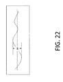
- FIG. 22 graphically represents the total peak-to-valley of waviness profile
- FIG. 23 graphically represents the mean spacing, Sm.
- Certain embodiments of the present invention may be especially suited for placement between adjacent human vertebral bodies.
- the implants of the present invention may be used in procedures such as Anterior Lumbar Interbody Fusion (ALIF) (e.g., FIG. 4A ), Posterior Lumbar Interbody Fusion (PLIF) (e.g., FIG. 15 ), Transforaminal Lumbar Interbody Fusion (TLIF) (e.g., FIG. 14 ), cervical fusion or Anterior Cervical implants (e.g., FIG. 17 ), and laterally placed lumbar implants (e.g., FIG. 16 ). Certain embodiments do not extend beyond the outer dimensions of the vertebral bodies.
- ALIF Anterior Lumbar Interbody Fusion
- PLIF Posterior Lumbar Interbody Fusion
- TLIF Transforaminal Lumbar Interbody Fusion
- FIG. 17 cervical fusion
- laterally placed lumbar implants e.g., FIG. 16 .
- Certain embodiments do not extend beyond the outer dimensions of the vertebral bodies.
- interbody spinal implants allow for improved seating over the apophyseal rim of the vertebral body. Still further, interbody spinal implants, as now taught, better utilize this vital surface area over which fusion may occur and may better bear the considerable biomechanical loads presented through the spinal column with minimal interference with other anatomical or neurological spinal structures. Even further, interbody spinal implants, according to certain aspects of the present invention, allow for improved visualization of implant seating and fusion assessment.
- Interbody spinal implants may also facilitate osteointegration (e.g., formation of a direct structural and functional interface between the artificial implant and living bone) with the surrounding living bone.
- interbody spinal implants may enhance friction, stabilize the implant during and after implantation, disperse the load applied across the implant, and prevent or minimize damage to the vertebral endplates during and after implantation.
- implant fixation may depend, at least in part, on the stimulation and proliferation of bone modeling and forming cells, such as osteoclasts and osteoblasts and like-functioning cells, upon the implant surface. Still further, it appears that these cells attach more readily to relatively rough surfaces rather than smooth surfaces. In this manner, a surface may be bioactive due to its ability to stimulate bio-chemical reaction, cellular attachment and osteointegration.
- the roughened surface topography of the integration plate(s) described in this document may better promote the osteointegration of certain embodiments of the present invention.
- the roughened surface topography of the integration plate(s) may also better grip the vertebral endplate surfaces, provide stability, and inhibit implant migration upon placement and seating as well as avoid or minimize damage to the vertebral endplate surfaces.
- FIG. 4A shows a perspective view of a first embodiment of the interbody spinal implant 1 especially well adapted for use in an ALIF procedure.
- FIG. 4B shows a top view of the first embodiment.
- the interbody spinal implant 1 includes a body 2 having a top surface 10 , a bottom surface 20 , opposing lateral sides 30 , and opposing anterior 40 and posterior 50 portions.
- the interbody spinal implant 1 may include implants made of a single piece of material or composite implants.
- Interbody spinal implants 1 made of a single piece of material do not include integration plates 82 .
- the integration surface may include the top surface 10 of the body 2 of the implant 1 , the bottom surface 20 of the body 2 of the implant 1 , or both surfaces.
- the integration surfaces may have a roughened surface topography 80 without sharp teeth that risk damage to bone structures.
- the implant 1 may be composed of a suitable biocompatible material.
- implant 1 is formed of metal.
- the metal may be coated or not coated. Suitable metals, such as titanium, aluminum, vanadium, tantalum, stainless steel, and alloys of those metals, may be selected by one of ordinary skill in the art. In a preferred embodiment, however, the metal is at least one of titanium, aluminum, and vanadium, without any coatings.
- the implant 1 is comprised of titanium or a titanium alloy.
- An oxide layer may naturally form on a titanium or titanium alloy. Titanium and its alloys are generally preferred for certain embodiments of the present invention due to their acceptable, and desirable, strength and biocompatibility. In this manner, certain embodiments of the present interbody spinal implant 1 may have improved structural integrity and may better resist fracture during implantation by impact.
- Composite implants 1 include at least a body 2 and one or two integration plates 82 , which may be formed from the same or different materials. As depicted in FIG. 12 , the implant 1 may include an optional first integration plate 82 affixed to the top surface 10 of the body 2 and an optional second integration plate 82 affixed to the bottom surface 20 of the body 2 (see FIG. 13 ).
- the optional first integration plate 82 and optional second integration plate 82 each have a top surface 81 , a bottom surface 83 , opposing lateral sides, an opposing anterior portion 41 and a posterior portion 51 , and a single vertical aperture 61 extending from the top surface 81 to the bottom surface 83 and aligning with a single vertical aperture 60 of the body 2 .
- the integration plate(s) 82 may comprise an integration surface (e.g., the top surface 81 of the first integration plate 82 , the top surface 81 of the second integration plate 82 , or both surfaces), which is adapted to grip bone through friction generated when the implant 1 is placed between two vertebrae and to inhibit migration of the implant 1 once implanted.
- the integration surfaces may also have a fusion stimulating and biologically active surface geometry.
- at least a portion of the top surface 81 of the first integration plate 82 e.g., a first integration surface
- a top surface 81 of the second integration plate 82 e.g., a second integration surface
- the roughened surface topography 80 may include macro features of a regular repeating pattern, which may promote biological and chemical attachment or fusion with the bone structure.
- the body 2 and at least one integration plate 82 are preferably compatibly shaped, such that the implant 1 having the body 2 and integration plate(s) 82 joined together may have a generally oval shape, a generally rectangular shape, a generally curved shape, or any other shape described or exemplified in this specification.
- the body 2 and the integration plate(s) 82 may be generally oval-shaped in transverse cross-section.
- the body 2 and the integration plate(s) 82 may be generally rectangular-shaped in transverse cross-section.
- the body 2 and the integration plate(s) 82 may be generally curved-shaped in transverse cross-section.
- the body 2 and integration plate(s) 82 of the implant 1 may be the same material or may be different.
- the body 2 and the integration plate(s) 82 may be composed of a suitable biocompatible material.
- the body 2 and optional integration plate(s) 82 are formed of metal, which may be coated or not coated. Suitable metals, such as titanium, aluminum, vanadium, tantalum, stainless steel, and alloys of the metals, may be selected by one of ordinary skill in the art. In a preferred embodiment, however, the metal is at least one of titanium, aluminum, and vanadium, without any coatings.
- the body 2 and optional integration plate(s) 82 are comprised of titanium or a titanium alloy. An oxide layer may naturally form on a titanium or titanium alloy.
- the body 2 may be composed of a non-metal biocompatible material.
- the body 2 of the implant 1 is formed of a plastic, polymeric, or composite material.
- suitable polymers may comprise silicones, polyolefins, polyesters, polyethers, polystyrenes, polyurethanes, acrylates, and co-polymers and mixtures of the polymers.
- Certain embodiments of the present invention may be comprised of a biocompatible, polymeric matrix reinforced with bioactive fillers, fibers, or both.
- Certain embodiments of the present invention may be comprised of urethane dimethacrylate (DUDMA)/tri-ethylene glycol dimethacrylate (TEDGMA) blended resin and a plurality of fillers and fibers including bioactive fillers and E-glass fibers.
- the body 2 comprises polyetherether-ketone (PEEK), hedrocel, or ultra-high molecular weight polyethylene (UHMWPE).
- PEEK polyetherether-ketone
- Hedrocel is a composite material composed of carbon and an inert metal, such as tantalum.
- UHMWPE also known as high-modulus polyethylene (HMPE) or high-performance polyethylene (HPPE)
- HMPE high-modulus polyethylene
- HPPE high-performance polyethylene
- interbody spinal implant 1 are substantially hollow and have a generally oval-shaped transverse cross-sectional area.
- substantially hollow means at least about 33% of the interior volume of the interbody spinal implant 1 is vacant.
- the substantially hollow portion may be filled with graft materials, such as cancellous autograft bone, allograft bone, demineralized bone matrix (DBM), porous synthetic bone graft substitute, bone morphogenic protein (BMP), or combinations of those materials.
- graft materials such as cancellous autograft bone, allograft bone, demineralized bone matrix (DBM), porous synthetic bone graft substitute, bone morphogenic protein (BMP), or combinations of those materials.
- the implant 1 may include an integration surface on at least a portion of the top surface, bottom surface, or both surfaces.
- the integration surface is the surface at least partially in contact with the vertebral endplate or bone structure.
- the composition of the endplate is a thin layer of notch-sensitive bone that is easily damaged by features (such as teeth) that protrude sharply from the surface of traditional implants.
- FIGS. 1-3 depict the types of problems that may be encountered by traditional implants P 1 with teeth P 80 or sharp surface features, for example, protruding from an integration surface.
- FIG. 1A depicts a perspective view and FIG. 1B depicts a side view of an example of a traditional implant P 1 having sharp, protruding teeth P 80 on the top surface P 10 and the bottom surface P 20 of the implant P 1 .
- FIGS. 1A and 1B shows an array of teeth P 80 each having a square pyramid shape, but any shape, number, or arrangement of sharp, protruding teeth P 80 may cause a problem.
- the terminus of these sharp, protruding teeth P 80 may be a point or other sharp or jagged area.
- FIG. 2 shows an example of the damage that may occur to a vertebral endplate P 25 during and after insertion of an implant P 1 having teeth P 80 , for example, when the implant P 1 is seated between vertebrae using impact forces.
- FIG. 2( a ) shows the condition of the endplate P 25 prior to implantation.
- FIG. 2( b ) shows the effect on the vertebral endplate P 25 when the implant P 1 of FIG. 1A is implanted or force fit into the joint space.
- FIG. 2( c ) illustrates the type of damage that may result to the vertebral endplate P 25 due to implant teeth P 80 .
- the protruding teeth P 80 damage, scribe, and degrade the vertebral endplate P 25 by causing a number of grooves or ridges in the vertebrae where the teeth P 80 contact the surface of the vertebral endplate 25 .
- This scribing can also significantly reduce the amount of expulsion resisting friction as the teeth are aligned in the direction of implantation and as the first feature cuts a path into the endplate the subsequent teeth follow in the cut channel and have no bone behind them to act against the expulsion forces.
- a similar result may occur from the top surface P 10 of the implant P 1 contacting an upper vertebral endplate 25 .
- FIG. 3 depicts the type of damage that may occur under a focused load on the implant P 1 once inserted into position.
- FIG. 3( a ) shows the implant P 1 in contact with the vertebral endplate P 25 once implanted.
- the implant P 1 may be unstable during implantation because only the points of the teeth directly contact the bone.
- the implant P 1 may be subject to movement (e.g., side to side, front to back, or twisting) due to the poor contact with the bone structure.
- FIG. 3( b ) shows the effect of bone remodeling as the sharp teeth P 80 continue to press on the vertebrae under the load and over time.
- FIG. 3( c ) depicts the type of resulting damage P 26 that may occur after some period of time of continued load on the vertebral endplate P 25 .
- FIG. 3( d ) depicts the vertebrae with the implant P 1 removed and the amount of damage P 26 which may be caused to the vertebral endplate P 25 .
- the integration surfaces of the present invention do not have teeth, undercuts, or other sharp, potentially damaging structures; rather, the integration surfaces have a pattern of repeating features of predetermined sizes, smooth shapes, and orientations.
- the integration surfaces comprise an organized arrangement of predefined surface features that provide one or more of the following functions: (a) engage the vertebral endplates with a friction fit; (b) attain initial stabilization during implantation; (c) attain permanent stabilization once implanted; (d) evenly distribute and disperse the load across the implant from the vertebral endplates; (e) do not damage the vertebral endplates (e.g., do not shave, shear, or remodel the endplates during or after implantation); and (f) benefit fusion.
- the integration surface may include the top surface, the bottom surface, or both surfaces of the implant 1 .
- this would include the top 10 , bottom 20 , or both surfaces of the body 2 of the implant 1 .
- this would include the top 81 of the integration plate 82 , the bottom 20 of the body 2 , or both surfaces.
- this would include the top 10 of the body 2 , the top 81 of the integration plate 82 (i.e., the outer surface of the integration plate 82 at the bottom of the implant), or both surfaces.
- the integration surface preferably includes a predetermined repeating pattern formed of at least three at least partially overlapping repeated patterns.
- predetermined means determined beforehand, so that the predetermined characteristic must be determined, i.e., chosen or at least known, before use of the implant.
- the design may produce surfaces that resist motion induced by loading in specific directions that are beneficial to the installation process and resist the opposing forces that can be the result of biologic or patient activities such as standing, bending, or turning or as a result of other activities.
- the shapes of the surface features, when overlapping, work to increase the surface contact area but do not result in undercuts that generate a cutting or aggressively abrasive action on the contacting bone surfaces.
- the repeating pattern is formed of at least three at least partially overlapping repeating patterns comprising a first repeating pattern 103 , a second repeating pattern 105 , and a third repeating pattern 107 .
- the repeating pattern may include any number of patterns, three or more, as is necessary to achieve the desired surface structure. By overlapping, it is intended that the first repeating pattern 103 and second repeating pattern 105 , the second repeating pattern 105 and third repeating pattern 107 , the first repeating pattern 103 and third repeating pattern 107 , all three patterns, or any subsequent patterns at least partially contact one another and overlay the other pattern or patterns.
- Each of the patterns may include a designed configuration of surface features including recesses or protrusions in a shape, such as dots, circles, semi-circles, spheres, semi-spheres, squares, cubes, polyhedral pyramids, triangles, lines, strips, amorphous shapes, or any suitable pattern designed to not align with the direction of implantation, provide frictional contact with opposing bones, and disperse loading.
- the patterns include a plurality of recesses in the shape of spheres or semi-spheres.
- the pattern may consist of an array of shapes or structures.
- the array may include a systematic arrangement of recesses or objects in rows, columns, or both.
- FIG. 5 depicts an example of a first repeating pattern 103 arranged as an array (e.g., columns and rows) of spherical shapes.
- FIG. 6 depicts an example of a second repeating pattern 105 arranged as an array (e.g., columns and rows) of spherical shapes.
- FIG. 7 depicts an example of a third repeating pattern 107 arranged as an array (e.g., columns and rows) of spherical shapes.
- FIG. 11 depicts the resulting pattern (e.g., a roughened surface topography 80 ) of overlapping the patterns shown in FIGS. 5 , 6 , and 7 .
- the pattern may also include a radial pattern.
- subsequent patterns may radiate outward at a fixed distance from one or more points from a first or previous pattern.
- the pattern may radiate from a point by shifting the second repeating pattern 105 and the third repeating pattern 107 (or subsequent patterns) in the x-axis, the y-axis, or both the x-axis and y-axis.
- the second repeating pattern 105 , the third repeating pattern 107 , or both repeating patterns may radiate at a fixed distance from at least one point defined by the first repeating pattern 103 .
- FIG. 9 depicts the first repeating pattern 103 and the second repeating pattern 105 from FIGS.
- FIG. 10 depicts the second repeating pattern 105 and third repeating pattern 107 from FIGS. 7 and 8 , respectively, where the third pattern 107 radiates at a fixed distance in both the x- and y-axis from the first repeating pattern 103 and the second repeating pattern 105 .
- Each of the three repeating patterns preferably contains no sharp points or undercuts. Sharp points and undercuts may be avoided, for example, by forming recesses having a slope of less than 90° relative to the integration surface. The slope is measured based on the angle A of the side of the recess (e.g., a tangent line) as compared to the plane of the integration surface (e.g., the integration surface equals 0°).
- FIGS. 8( a ) and ( b ) depict examples of recesses having slopes of less than 90° relative to the integration surface (e.g., about 20° and about 10°, respectively).
- FIG. 8( c ) shows an example of a recess having a slope greater than 90° (e.g., about 130°), which produces an undercut or sharp point not in accordance with the present invention.
- the slope of the recess may be controlled based on the shape of the recess, the depth of the recess, and the diameter of the recess.
- FIGS. 8( a ), ( b ), and ( c ) each comprise the same diameter d recess, but each recess has a different depth, different angle A, and thus a different slope.
- FIG. 8( c ) has the greatest depth and the greatest angle A, which at more than 90° produces an undesired undercut.
- FIG. 8( b ) has the smallest depth and the smallest angle A.
- FIG. 8( c ) is greater in depth than FIG. 8( b ) and thus produces a bigger angle A and greater slope.
- each of the repeating patterns have recesses with slopes of 30° or less, 25° or less, 20° or less, 15° or less, 10° or less, or 5° or less based on the integration surface.
- the first repeating pattern 103 includes recesses having a slope of 30° or less relative to the integration surface
- the second repeating pattern 105 includes recesses having a slope of 25° or less relative to the integration surface
- the third repeating pattern 107 includes recesses having a slope of 20° or less relative to the integration surface.
- the patterns may include recesses having the same or varying diameters, depths, and spacings.
- the three repeating patterns each comprise spheres or semi-spheres having varying diameters.
- the first repeating pattern 103 has the greatest depth
- the second repeating pattern 105 has an intermediate depth
- the third repeating pattern 107 has the smallest depth.
- the spacing of the at least three repeating patterns may be as follows: the first repeating pattern 103 may have a spacing S1, the second repeating pattern 105 may have a spacing S2, and the third repeating pattern 107 may have a spacing S3, where the spacing S1 is less than the spacing S3 which, in turn, is less than the spacing S2.
- the spacing may be based on the spacing between each of the recesses or protrusions in the pattern (e.g., a distance from center point to center point of each recess along the x-axis and y-axis).
- each of the three repeating patterns have features with diameters, depths, and spacings which are sequentially sized and positioned to preserve an amount of the features and patterns from the previous pattern or patterns.
- these designed surfaces are composed of various sizes of features that may interact, at the microscopic level, with the tissues and stimulate their natural remodeling and growth. At a larger scale these features perform the function of generating non-stressful friction that allows for a friction fit that does not abrade, chip, perforate, or compromise the critical endplate structures.
- the surface features are uni-directionally oriented such that the implant may be inserted in one direction but cannot back out once implanted (e.g., resist expulsion).
- the shapes of the surface protrusions or recesses may be formed by a subtractive process, an additive process, or both processes.
- the shapes may be formed using processes and methods commonly applied to remove material (e.g., subtractive techniques) during fabrication of implantable devices such as chemical, electrical, electrochemical, plasma, or laser etching; cutting and removal processes; casting; forging; machining; drilling; grinding; shot peening; abrasive media blasting (such as sand or grit blasting); combinations of these subtractive processes; and others known in the art.
- the shapes may be formed using methods commonly applied to add material (e.g., additive processes) to a surface such as welding, thermal, coating, sputtering, printing, optical melt additive processes, and other additive processes known in the art.
- the additive or subtractive process may include macro, micro, or nano surface features.
- FIG. 18 illustrates one set of process steps that can be used to form macro, micro, or nano features.
- the term “macro” typically means relatively large; for example, in the present application, dimensions measured in millimeters (mm).
- the term “micro” typically means one millionth (10 ⁇ 6 ); for example, in the present application, dimensions measured in microns ( ⁇ m) which correspond to 10 ⁇ 6 meters.
- nano typically means one billionth (10 ⁇ 9 ); for example, in the present application, dimensions measured in nanometers (nm) which correspond to 10 ⁇ 9 meters. As illustrated in FIG.
- the at least three repeating patterns are formed of macro-sized features (although it is contemplated that micro- and nano-sized features may also be included).
- the macro features are relatively large features (e.g., on the order of millimeters).
- the macro features are formed by subtractive techniques, which remove at least portions of the surface (e.g., from the titanium material that was used to form the part).
- Suitable subtractive techniques may include, for example, machining (e.g., machine tools, such as saws, lathes, milling machines, and drill presses, are used with a sharp cutting tool to physically remove material to achieve a desired geometry) or unmasked or masked etching (e.g., portions of the surface are protected by a masking material which resists etching and an etching substance is applied to unmasked portions).
- machining e.g., machine tools, such as saws, lathes, milling machines, and drill presses, are used with a sharp cutting tool to physically remove material to achieve a desired geometry
- unmasked or masked etching e.g., portions of the surface are protected by a masking material which resists etching and an etching substance is applied to unmasked portions.
- the three repeating patterns may include overlapping patterns shown in FIGS. 5-7 and 9 - 11 .
- FIG. 5 illustrates the result of one step or a first step in forming macro features. Specifically, a first pattern 103 of the macro features is cut or formed in a surface (e.g., the top surface 81 of an integration plate 82 ).
- FIG. 6 illustrates the result of a second step in forming macro features. Specifically, a second pattern 105 of the macro features is cut or formed in the surface.
- FIG. 7 illustrates the result of the third step in forming macro features. Specifically, a third pattern 107 of the macro features may be cut or formed in the surface.
- the process includes forming first-cut surface features having a spacing S1 and a greatest depth; forming second-cut surface features having a spacing S2 and an intermediate depth; and forming third-cut surface features having a spacing S3 and a smallest depth, where the spacing S1 ⁇ spacing S3 ⁇ spacing S2.
- the finished macro features may comprise multiple patterns of the three, overlapping cuts: the first pattern 103 , the second pattern 105 , and the third pattern 107 , for example, as depicted as the roughened surface topography 80 in FIG. 11 .
- the “cut 1 ” features of the first pattern 103 , the “cut 2 ” features of the second pattern 105 , and the “cut 3 ” features of the third pattern 107 may cover about 95% of the total area of the surface, for example, leaving about 5% of the original surface remaining.
- the surface features cover about 97% of the total area of the surface.
- the at least three repeating patterns cover substantially all of the integration surface.
- the process steps described in this document can be adjusted to create a mixture of depths, diameters, feature sizes, and other geometries suitable for a particular implant application.
- the orientation of the pattern of features can also be adjusted. Such flexibility is desirable, especially because the ultimate pattern of the surface topography desired, for example, the integration surface of the implant 1 may be oriented in opposition to the biologic forces on the implant 1 and to the insertion direction.
- the pattern of the roughened surface topography 80 may be modeled after an S-shaped tire tread. It is also contemplated that the same or different process steps may be used to create each of the features on each of the desired surfaces.
- the five parameters are: (1) average amplitude, Ra; (2) average peak-to-valley roughness, Rz; (3) maximum peak-to-valley height, Rmax; (4) total peak-to-valley of waviness profile, Wt; and (5) mean spacing, Sm.
- Each parameter is explained in detail as follows.
- Ra is the most commonly used roughness parameter. It is the arithmetic average height. Mathematically, Ra is computed as the average distance between each roughness profile point and the mean line. In FIG. 19 , the average amplitude is the average length of the arrows.
- the average peak-to-valley roughness, Rz is defined by the ISO and ASME 1995 and later. Rz is based on one peak and one valley per sampling length. The RzDIN value is based on the determination of the peak-to-valley distance in each sampling length. These individual peak-to-valley distances are averaged, resulting in the RzDIN value, as illustrated in FIG. 20 .
- the maximum peak-to-valley height, Rmax is the maximum peak-to-valley distance in a single sampling length—as illustrated in FIG. 21 .
- the total peak-to-valley of waviness profile (over the entire assessment length) is illustrated in FIG. 22 .
- the mean spacing, Sm is the average spacing between positive mean line crossings.
- the distance between each positive (upward) mean line crossing is determined and the average value is calculated, as illustrated in FIG. 23 .
- the parameters Sm, Rmax, and Ra can be used define the surface roughness following formation of each of the three types of macro features.
- the following preferred ranges are as follows for the macro features for each of the three parameters.
- the mean spacing, Sm is between about 400-2,000, with a range of 750-1,750 preferred and a range of 1,000-1,500 most preferred.
- the maximum peak-to-valley height, Rmax is between about 40-500, with a range of 150-400 preferred and a range of 250-300 most preferred.
- the average amplitude, Ra is between about 8-200, preferably, 20-200, more preferably 50-150, and most preferably 100-125.
- the integration plate shown in the drawing as component 82 ( FIGS. 12 and 13 ), 182 a ( FIG. 14 ), 182 ( FIG. 15 ), 382 ( FIG. 16 ), and 282 ( FIG. 17 ), respectively, includes the roughened surface topography 80 , 180 , 180 a , 280 , and 380 for the integration surface, and is connectable to either or both of the top surface 10 , 110 , 110 a , 210 , and 310 or bottom surface 20 , 120 , 120 a , 220 , and 320 .
- the integration plate 82 , 182 , 182 a , 282 , and 382 includes a top surface 81 , 181 , 181 a , 281 , and 381 ; a bottom surface 83 , 183 , 183 a , 283 , and 383 ; an anterior portion 41 , 141 , 141 a , 241 , and 341 ; a posterior portion 51 , 151 , 151 a , 251 , and 351 ; and at least one vertical aperture 61 , 161 , 161 a , 261 , and 361 .
- the anterior portion 41 , 141 , 141 a , 241 , and 341 preferably aligns with the anterior portion 40 , 140 , 140 a , 240 , and 340 of the main body 2 of the implant 1 , 101 , 101 a , 201 , and 301 , respectively, and the posterior portion 51 , 151 , 151 a , 251 , and 351 aligns with the posterior portion 50 , 150 , 150 a , 250 , and 350 of the main body 2 of the implant 1 , 101 , 101 a , 201 , and 301 , respectively.
- the vertical aperture 61 , 161 , 161 a , 261 , and 361 preferably aligns with the vertical aperture 60 , 160 , 160 a , 260 , and 360 of the main body 2 of the implant 1 , 101 , 101 a , 201 , and 301 , respectively.
- the integration plate vertical aperture 61 , 161 , 161 a , 261 , and 361 and the body vertical aperture 60 , 160 , 160 a , 260 , and 360 preferably comprise substantially the same shape.
- the integration plate 82 , 182 , 182 a , 282 , and 382 may be attached or affixed to the main body of the implant 1 , 101 , 101 a , 201 , and 301 using any suitable mechanisms known in the art.
- the bottom surface 83 , 183 , 183 a , 283 , and 383 of the integration plate 82 , 182 , 182 a , 282 , and 382 may comprise a reciprocal connector structure, such as a plurality of posts 84 , 184 , 184 a , 284 , and 384 that align with and insert into a corresponding connector structure such as a plurality of holes 12 , 112 , 112 a , 212 , and 312 on the top surface 10 , 110 , 110 a , 210 , and 310 and/or bottom surface 20 , 120 , 120 a , 220 , and 320 of the main body 2 of the implant 1 , 101 , 101 a , 201 , and 301 , respectively, and thus facilitate the connection between the integration plate 82 , 182 , 182 a , 282 , and 382 and the main body 2 of the implant 1 , 101 , 101 a , 301
- integration plates 82 , 182 , 182 a , 282 , and 382 with different sizes, shapes, or features may be used in connection with the implant 1 , 101 , 101 a , 201 , and 301 , for example, to accommodate attributes of the spine of the patient into which the implant 1 , 101 , 101 a , 201 , and 301 is to be implanted.
- these different sizes, shapes, and features are lordotic angles; anti-expulsion edges 8 , 108 , 108 a , 208 , and 308 ; and anti-expulsion angles as described throughout this specification.
- the implant 1 , 101 , 101 a , 201 , and 301 is configured to receive the integration plate 82 , 182 , 182 a , 282 , and 382 , respectively.
- the top surface 10 , 110 , 110 a , 210 , and 310 and/or bottom surface 20 , 120 , 120 a , 220 , and 320 of the implant 1 , 101 , 101 a , 201 , and 301 may be optionally recessed, and comprise a plurality of holes 12 , 112 , 112 a , 212 , and 312 that mate with the plurality of posts 84 , 184 , 184 a , 284 , and 384 on the bottom surface 83 , 183 , 183 a , 283 , and 383 of the integration plate 82 , 182 , 182 a , 282 , and 382 .
- FIG. 5 shows that the top surface 10 is recessed and comprises a plurality of holes 12 , but the recessed bottom surface 20 and its holes 12 are not shown.
- FIG. 7 shows that the top surface 110 a is recessed and comprises a plurality of holes 112 a , but the recessed bottom surface 120 a and its holes 112 a are not shown.
- FIG. 9 shows that the top surface 110 is recessed and comprises a plurality of holes 112 , but the recessed bottom surface 120 and its holes 112 are not shown.
- FIG. 10 shows that the top surface 310 is recessed and comprises a plurality of holes 312 , but the recessed bottom surface 320 and its holes 312 are not shown.
- top surface 210 is recessed and comprises a plurality of holes 212 , but the recessed bottom surface 220 and its holes 212 are not shown.
- the recess may be at a depth D, and the recess depth D preferably is uniform throughout the top surface 10 , 110 , 110 a , 210 , and 310 and/or bottom surface 20 , 120 , 120 a , 220 , and 320 .
- the recess depth D preferably corresponds to a thickness T of the integration plate 82 , 182 , 182 a , 282 , and 382 .
- the depth D and thickness T are the same so that once the integration plate 82 , 182 , 182 a , 282 , and 382 and body of the implant 1 , 101 , 101 a , 201 , and 301 , respectively, are placed together, the top surface 10 , 110 , 110 a , 210 , and 310 and/or bottom surface 20 , 120 , 120 a , 220 , and 320 of the implant 1 , 101 , 101 a , 201 , and 301 is substantially even, at least at the seam/junction between the integration plate 82 , 182 , 182 a , 282 , and 382 and the top surface 10 , 110 , 110 a , 210 , and 310 or bottom surface 20 , 210 , 120 a , 2
- the posterior portion 51 , 151 , 151 a , 251 , and 351 and the anterior portion 41 , 141 , 141 a , 241 , and 341 of the integration plate 82 , 182 , 182 a , 282 , and 382 have different thicknesses such that the anterior portion 41 , 141 , 141 a , 241 , and 341 has a greater thickness than the thickness of the posterior portion 51 , 151 , 151 a , 251 , and 351 .
- the recess depth D and the thickness T may each independently be from about 0.1 mm to about 10 mm. In preferred aspects, the recess depth D and the thickness T may each independently be from about 1 mm to about 5 mm. Thus, for example, the recess depth D or the thickness T may be selected from about 0.1 mm, about 0.25 mm, about 0.5 mm, about 0.75 mm, about 1 mm, about 1.25 mm, about 1.5 mm, about 1.75 mm, about 2 mm, about 2.25 mm, about 2.5 mm, about 2.75 mm, about 3 mm, about 3.25 mm, about 3.5 mm, about 3.75 mm, about 4 mm, about 4.25 mm, about 4.5 mm, about 4.75 mm, about 5 mm, 5.5 mm, about 6 mm, about 6.5 mm, about 7 mm, about 75 mm, or about 8 mm.
- Recessing the top surface 10 , 110 , 110 a , 210 , and 310 or bottom surface 20 , 120 , 120 a , 220 , and 320 exposes a ridge 11 , 111 , 111 a , 211 , and 311 against which the anterior portion 41 , 141 , 141 a , 241 , and 341 ; posterior portion 51 , 151 , 151 a , 251 , and 251 ; or lateral side of the integration plate 82 , 182 , 182 a , 282 , and 382 may be seated when brought together with the implant 1 , 101 , 101 a , 201 , and 301 .
- the integration plate 82 , 182 , 182 a , 282 , and 382 may be used with an implant suitable for ALIF (e.g., implant 1 , integration plate 82 ), PLIF (e.g., implant 101 , integration plate 182 ), or TLIF fusion (e.g., implant 101 a , integration plate 182 a ); may be used with an implant suitable for cervical fusion (e.g., implant 201 , integration plate 282 ); and may be used with an implant suitable for lateral lumbar insertion (e.g., implant 301 , integration plate 382 ).
- ALIF e.g., implant 1 , integration plate 82
- PLIF e.g., implant 101 , integration plate 182
- TLIF fusion e.g., implant 101 a , integration plate 182 a
- an implant suitable for cervical fusion e.g., implant 201 , integration plate 282
- the reciprocal connector such as the post 84 , 184 , 184 a , 284 , and 384 preferably is secured within the connector of the body such as the hole 12 , 112 , 112 a , 212 , and 312 to mediate the connection between the integration plate 82 , 182 , 182 a , 282 , and 382 and the implant 1 , 101 , 101 a , 201 , and 301 .
- the connection should be capable of withstanding significant loads and shear forces when implanted in the spine of the patient.
- connection between the post 84 , 184 , 184 a , 284 , and 384 and the hole 12 , 112 , 112 a , 212 , and 312 may comprise a friction fit.
- the reciprocal connector such as the post 84 , 184 , 184 a , 284 , and 384 and the connector of the body such as the hole 12 , 112 , 112 a , 212 , and 312 have additional compatible structures and features to further strengthen the connection between the integration plate 82 , 182 , 182 a , 282 , and 382 and the implant 1 , 101 , 101 a , 201 , and 301 .
- the structures and features may be on either or both of the integration plate 82 , 182 , 182 a , 282 , and 382 and the main body 2 of the implant 1 , 101 , 101 a , 201 , and 301 .
- the structures include fasteners, compatibly shaped joints, compatibly shaped undercuts, and/or other suitable connectors having different shapes, sizes, and configurations.
- a fastener may include a pin, screw, bolt, rod, anchor, snap, clasp, clip, clamp, or rivet.
- an adhesive may be used to further strengthen any of the integration plate 82 , 182 , 182 a , 282 , and 382 and implant 1 , 101 , 101 a , 201 , and 301 connections described in this specification.
- An adhesive may comprise cement, glue, polymer, epoxy, solder, weld, or other suitable binding materials.
- the integration plate 82 , 182 , 182 a , 282 , and 382 may comprise one or more reciprocal connectors (not shown), such as one or more posts, each having a bore, extending through a horizontal plane.
- the post may be inserted into a connector such as a hole through the implant 1 , 101 , 101 a , 201 , and 301 .
- a fastener (not shown), such as a pin, may be inserted through the bore thereby preventing the post from being disengaged from the hole.
- the pin may be threaded through a second bore that passes through the walls of the implant 1 , 101 , 101 a , 201 , and 301 itself; although it is preferable that the implant 1 , 101 , 101 a , 201 , and 301 does not include a second bore through its walls and that the bore is accessible from the space inside of the implant.
- the integration plate 82 , 182 , 182 a , 282 , and 382 may comprise a plurality of bores (not shown) present on and having openings accessible from the bottom of the integration plate 82 , 182 , 182 a , 282 , and 382 .
- the bores may mate with a plurality of fasteners, which may comprise rods integral with or otherwise attached to the top surface or bottom surface of the implant 1 , 101 , 101 a , 201 , and 301 .
- the rods may be molded as upward-facing extensions or snap-fit into the bores.
- the hole 12 , 112 , 112 a , 212 , and 312 may not be present, and the screw or bolt (not shown) may be screwed directly into the plastic or polymeric material, with the screw threads tightly gripping the plastic or polymeric material to form the connection.
- the bottom surface 83 , 183 , 183 a , 283 , and 383 of the integration plate 82 , 182 , 182 a , 282 , and 382 may comprise undercuts (not shown) in shapes that foam a tight junction with compatible shapes on the implant 1 , 101 , 101 a , 201 , and 301 .
- the bottom surface 83 , 183 , 183 a , 283 , and 383 may comprise a dovetail joint, bevel, or taper that fits with a counterpart dovetail joint, bevel, or taper on the body 2 of the implant 1 , 101 , 101 a , 201 , and 301 .
- An adhesive may directly join the integration plate 82 , 182 , 182 a , 282 , and 382 and the body 2 of the implant 1 , 101 , 101 a , 201 , and 301 together, with or without other connecting features.
- the adhesive may be applied to the bottom surface 83 , 183 , 183 a , 283 , and 383 of the integration plate 82 , 182 , 182 a , 282 , and 382 .
- the adhesive may be applied to the top surface 10 , 110 , 110 a , 210 , and 310 ; the bottom surface 20 , 120 , 120 a , 220 , and 320 ; or both surfaces of the implant 1 , 101 , 101 a , 201 , and 301 .
- the foregoing describes various non-limiting examples of how the one or two integration plates 82 , 182 , 182 a , 282 , and 382 may be joined together with the implant 1 , 101 , 101 a , 201 , and 301 .
- the implant 1 may comprise some or all of the following implant features.
- the interbody spinal implant 1 is substantially hollow and has a generally oval-shaped transverse cross-sectional area with smooth, rounded, or both smooth and rounded lateral sides 30 and posterior-lateral corners.
- the implant 1 includes at least one vertical aperture 60 that extends the entire height of the implant body 2 .
- the vertical aperture 60 defines an interior surface 60 a or hollow cavity within the implant 1 , which may be filled with bone growth-inducing materials.
- the vertical aperture (a) extends from the top surface to the bottom surface, (b) has a size and shape predetermined to maximize the surface area of the top surface and the bottom surface available proximate the anterior and posterior portions while maximizing both radiographic visualization and access to the substantially hollow center, and (c) optionally defines a transverse rim.
- the vertical aperture 60 may further define a transverse rim 100 having a greater posterior portion thickness 55 than an anterior portion thickness 45 .
- the opposing lateral sides 30 and the anterior portion 40 have a rim thickness 45 of about 5 mm, while the posterior portion 50 has a rim thickness 55 of about 7 mm.
- the rim posterior portion thickness 55 may allow for better stress sharing between the implant 1 and the adjacent vertebral endplates and helps to compensate for the weaker posterior endplate bone.
- the transverse rim 100 has a generally large surface area and contacts the vertebral endplate. The transverse rim 100 may act to better distribute contact stresses upon the implant 1 , and hence minimize the risk of subsidence while maximizing contact with the apophyseal supportive bone.
- transverse rim 100 it is also possible for the transverse rim 100 to have a substantially constant thickness (e.g., for the anterior portion thickness 45 to be substantially the same as the posterior portion thickness 55 ) or for the posterior portion 50 to have a rim thickness 55 less than that of the opposing lateral sides 30 and the anterior portion 40 .
- the implant 1 may be shaped to reduce the risk of subsidence, and improve stability, by maximizing contact with the apophyseal rim of vertebral endplates. Embodiments may be provided in a variety of anatomical footprints.
- An interbody spinal implant 1 generally does not require extensive supplemental or obstructive implant instrumentation to maintain the prepared disc space during implantation.
- the interbody spinal implant 1 and associated implantation methods allow for larger-sized implants as compared with other size-limited interbody spinal implants known in the art. This advantage allows for greater medial-lateral width and correspondingly greater contact with the apophyseal rim.
- the implant 1 may include other surface features including soft tissue surfaces.
- the soft tissue surface or insertion surface may include a low friction or smooth surface to avoid unintentional laceration or abrasion of delicate soft tissues the implant 1 contacts during insertion, after insertion, or both.
- the soft tissue surface may include any outer surfaces, other than the one or more integration surfaces, which may contact bone or soft tissues during or after implantation.
- the implant 1 may have an opening 90 in the anterior portion 40 .
- the posterior portion 50 may have a similarly shaped opening 90 (not shown).
- only the anterior portion 40 has the opening 90 while the posterior portion 50 has an alternative opening 92 (which may have a size and shape different from the opening 90 ).
- the opening 92 defines an interior surface or hollow cavity, which may be filled with bone growth-inducing materials.
- the interior surfaces defined by these openings may define graft retaining surfaces.
- the opening 90 , 290 , and 390 has a number of functions. One function is to facilitate manipulation of the implant 1 , 201 , and 301 by the caretaker.
- the caretaker may insert a surgical tool into the opening 90 , 290 , and 390 and, through the engagement between the surgical tool and the opening 90 , 290 , and 390 , manipulate the implant 1 , 201 , and 301 .
- the opening 90 , 290 , and 390 may be threaded to enhance the engagement.
- a suitable surgical tool such as a distractor (not shown), may be selected by one of ordinary skill in the art.
- the anterior portion 140 , 140 a may have a tapered nose 142 , 142 a to facilitate insertion of the implant 101 .
- the implant 1 may further include at least one transverse aperture 70 that extends the entire transverse length of the implant body.
- the transverse aperture 70 defines an interior surface or hollow cavity, which may be filled with bone growth-inducing materials.
- the at least one transverse aperture 70 may provide improved visibility of the implant 1 during surgical procedures to ensure proper implant placement and seating, and may also improve post-operative assessment of implant fusion.
- the transverse aperture 70 may be broken into two, separate sections by an intermediate wall. Suitable shapes and dimensions for the transverse aperture 70 may be selected by one of ordinary skill in the art. In particular, all edges of the transverse aperture 70 may be rounded, smooth, or both.
- the intermediate wall may be made of the same material as the remainder of the body 2 of the implant 1 (e.g., plastic), or it may be made of another material (e.g., metal).
- the intermediate wall may offer one or more of several advantages, including reinforcement of the implant 1 and improved bone graft containment.
- the implant 1 may be provided with a solid rear wall (not shown).
- the rear wall may extend the entire width of the implant body and nearly the entire height of the implant body. Thus, the rear wall can essentially close the anterior portion 40 of the implant 1 .
- the rear wall may offer one or more of several advantages, including reinforcement of the implant 1 and improved bone graft containment. In the cervical application, it may be important to prevent bone graft material from entering the spinal canal.
- the implant 1 may also have a lordotic angle to facilitate alignment.
- one lateral side 30 may be generally greater in height than the opposing lateral side 30 or the anterior portion 40 may be generally greater in height than the opposing posterior portion 50 . Therefore, the implant 1 may better compensate for the generally less supportive bone found in certain regions of the vertebral endplate.
- as much as fifteen degrees or as much as seven degrees of lordosis (or more) may be built into the implant 1 to help restore cervical balance.
- the implant 1 , 101 , 101 a , 201 , and 301 may comprise one or more anti-expulsion edges 8 , 108 , 108 a , 208 , and 308 that tend to “dig” into the end-plates slightly and help to resist expulsion.
- the anti-expulsion edges 8 , 108 , 108 a , 208 , and 308 may be present on the top surface 81 of the integration plate 82 affixed to the top surface 10 , 110 , 110 a , 210 , and 310 ; the bottom surface 20 , 120 , 120 a , 220 , and 320 ; or both surfaces of the implant 1 , 101 , 101 a , 201 , and 301 .
- the anti-expulsion edges 8 , 108 , 108 a , 208 , and 308 may be present on the top surface 10 , 110 , 110 a , 210 , and 310 ; the bottom surface 20 , 120 , 120 a , 220 , and 320 ; or both surfaces of the body of the implant 1 , 101 , 101 a , 201 , and 301 .
- FIG. 12 shows an anti-expulsion edge 8 on the top surface 81 of the integration plate 82 and the bottom surface 20 of the anterior face 40 of the implant 1 .
- Each anti-expulsion edge 8 may protrude above the plane of the top surface 81 of the integration plate 82 and bottom surface 20 , with the amount of protrusion increasing toward the anterior face 40 and the highest protrusion height P at the anterior-most edge of the top surface 81 of the integration plate 82 or bottom surface 20 .
- An anti-expulsion edge 8 , 108 , 108 a , 208 , and 308 may be oriented toward the anterior portion 40 , 140 , 140 a , 240 , and 340 , or the posterior portion 50 , 150 , 150 a , 250 , and 350 , or either of the opposing lateral sides 30 , 130 , 130 a , 230 , and 330 .
- the orientation of the anti-expulsion edge 8 , 108 , 108 a , 208 , and 308 may depend on the intended orientation of the implant 1 , 101 , 101 a , 201 , and 301 when it has been implanted between vertebrae in the patient.
- the disc space may be accessed using a standard mini open retroperitoneal laparotomy approach.
- the center of the disc space is located by AP fluoroscopy taking care to make sure the pedicles are equidistant from the spinous process.
- the disc space is then incised by making a window in the annulus for insertion of certain embodiments of the spinal implant 1 , 101 , 101 a , 201 , and 301 (a 32 or 36 mm window in the annulus is typically suitable for insertion).
- the process according to the invention minimizes, if it does not eliminate, the cutting of bone.
- the endplates are cleaned of all cartilage with a curette, however, and a size-specific rasp (or broach) may then be used.
- a rasp preferably substantially minimizes or eliminates removal of bone, thus substantially minimizing or eliminating impact to the natural anatomical arch, or concavity, of the vertebral endplate while preserving much of the apophyseal rim.
- Preservation of the anatomical concavity is particularly advantageous in maintaining biomechanical integrity of the spine. For example, in a healthy spine, the transfer of compressive loads from the vertebrae to the spinal disc is achieved via hoop stresses acting upon the natural arch of the endplate. The distribution of forces, and resultant hoop stress, along the natural arch allows the relatively thin shell of subchondral bone to transfer large amounts of load.
- the vertebral endplate natural arch may be significantly removed due to excessive surface preparation for implant placement and seating. This is especially common where the implant 1 , 101 , 101 a , 201 , and 301 is to be seated near the center of the vertebral endplate or the implant 1 , 101 , 101 a , 201 , and 301 is of relatively small medial-lateral width. Breaching the vertebral endplate natural arch disrupts the biomechanical integrity of the vertebral endplate such that shear stress, rather than hoop stress, acts upon the endplate surface. This redistribution of stresses may result in subsidence of the implant 1 , 101 , 101 a , 201 , and 301 into the vertebral body.
- interbody spinal implant 1 , 101 , 101 a , 201 , and 301 include smooth, rounded, and highly radiused posterior portions and lateral sides which may minimize extraneous bone removal for endplate preparation and reduce localized stress concentrations.
- interbody surgical implant 1 , 101 , 101 a , 201 , and 301 and methods of using it are particularly useful in preserving the natural arch of the vertebral endplate and minimizing the chance of implant subsidence.
- endplates are spared during the process of inserting the spinal implant 1 , 101 , 101 a , 201 , and 301 .
- Spared endplates allow the transfer of axial stress to the apophasis. Endplate flexion allows the bone graft placed in the interior of the spinal implant 1 , 101 , 101 a , 201 , and 301 to accept and share stress transmitted from the endplates.
- spared endplates minimize the concern that BMP might erode the cancellous bone.
- Interbody spinal implant 1 , 101 , 101 a , 201 , and 301 is durable and can be impacted between the endplates with standard instrumentation. Therefore, certain embodiments of the invention may be used as the final distractor during implantation. In this manner, the disc space may be under-distracted (e.g., distracted to some height less than the height of the interbody spinal implant 1 , 101 , 101 a , 201 , and 301 ) to facilitate press-fit implantation. Further, certain embodiments of the current invention having a smooth and rounded posterior portion (and lateral sides) may facilitate easier insertion into the disc space.
- the surface roughened topography 80 may lessen the risk of excessive bone removal during distraction as compared to implants having teeth, ridges, or threads currently known in the art even in view of a press-fit surgical distraction method. Nonetheless, once implanted, the interbody surgical implant 1 , 101 , 101 a , 201 , and 301 may provide secure seating and prove difficult to remove. Thus, certain embodiments of the interbody spinal implant 1 , 101 , 101 a , 201 , and 301 may maintain a position between the vertebral endplates due, at least in part, to resultant annular tension attributable to press-fit surgical implantation and, post-operatively, improved osteointegration.
- Surgical implants and methods according to embodiments of the invention tension the vertebral annulus via distraction. These embodiments may also restore spinal lordosis, thus improving sagittal and coronal alignment.
- Implant systems currently known in the art require additional instrumentation, such as distraction plugs, to tension the annulus. These distraction plugs require further tertiary instrumentation, however, to maintain the lordotic correction during actual spinal implant insertion. If tertiary instrumentation is not used, then some amount of lordotic correction may be lost upon distraction plug removal.
- Interbody spinal implant 1 , 101 , 101 a , 201 , and 301 is particularly advantageous in improving spinal lordosis without the need for tertiary instrumentation, thus reducing the instrument load upon the surgeon. This reduced instrument load may further decrease the complexity, and required steps, of the implantation procedure.
- spinal implant 1 , 101 , 101 a , 201 , and 301 may also reduce deformities (such as isthmic spondylolythesis) caused by distraction implant methods.
- Traditional implant systems require secondary or additional instrumentation to maintain the relative position of the vertebrae or distract collapsed disc spaces.
- interbody spinal implant 1 , 101 , 101 a , 201 , and 301 may be used as the final distractor and thus maintain the relative position of the vertebrae without the need for secondary instrumentation.
- Certain embodiments collectively comprise a family of implants, each having a common design philosophy. These implants and the associated surgical technique have been designed to address at least the ten, separate challenges associated with the current generation of traditional anterior spinal fusion devices listed above in the Background section of this document.
- embodiments of the invention first adequately distract the disc space by inserting (through impaction) and removing sequentially larger sizes of very smooth distractors, which have been size matched with the size of the available implant 1 , 101 , 101 a , 201 , and 301 . Once adequate distraction is achieved, the surgeon prepares the end-plate with a rasp. There is no secondary instrumentation required to keep the disc space distracted while the implant 1 , 101 , 101 a , 201 , and 301 is inserted, as the implant 1 , 101 , 101 a , 201 , and 301 has sufficient mechanical strength that it is impacted into the disc space.
- the height of the implant 1 , 101 , 101 a , 201 , and 301 is preferably about 1 mm greater than the height of the rasp used for end-plate preparation, to create some additional tension in the annulus by implantation, which creates a stable implant construct in the disc space.
- the implant geometry has features which allow it to be implanted via any one of an anterior, antero-lateral, or lateral approach, providing tremendous intra-operative flexibility of options.
- the implant 1 , 101 , 101 a , 201 , and 301 has adequate strength to allow impact, and the sides of the implant 1 , 101 , 101 a , 201 , and 301 may have smooth surfaces to allow for easy implantation and, specifically, to prevent binding of the implant 1 , 101 , 101 a , 201 , and 301 to soft tissues during implantation.
- the invention encompasses a number of different implant 1 , 101 , 101 a , 201 , and 301 configurations, including a composite implant formed of top and optional bottom plates (components), for example, made out of titanium.
- the integration surfaces exposed to the vertebral body have a roughened surface topography 80 to allow for bony in-growth over time, and to provide resistance against expulsion.
- the top and bottom titanium plates may be assembled together with the implant body 2 .
- the net result is a composite implant that has engineered stiffness for its clinical application.
- the axial load may be borne by the polymeric component of the construct.
- an intact vertebral end-plate deflects like a diaphragm under axial compressive loads generated due to physiologic activities. If a spinal fusion implant is inserted in the prepared disc space via a procedure which does not destroy the end-plates, and if the implant contacts the end-plates only peripherally, the central dome of the end-plates can still deflect under physiologic loads. This deflection of the dome can pressurize the bone graft material packed inside the spinal implant, hence allowing it to heal naturally.
- the implant 1 , 101 , 101 a , 201 , and 301 designed according to certain embodiments allows the vertebral end-plate to deflect and allows healing of the bone graft into fusion.
Abstract
Description
| TABLE |
| Surface Feature Size and Roughness (Metric): Macro (μm) |
| Size (Sm) | Depth (Rmax) | Roughness (Ra) | ||
| Max. | 2,000 | 500 | 200 | ||
| Min. | 400 | 40 | 20 | ||
| Avg. | 1,200 | 270 | 110 | ||
Claims (20)
Priority Applications (2)
| Application Number | Priority Date | Filing Date | Title |
|---|---|---|---|
| US13/607,890 US8758443B2 (en) | 2005-05-06 | 2012-09-10 | Implants with integration surfaces having regular repeating surface patterns |
| US14/293,291 US9327051B2 (en) | 2005-05-06 | 2014-06-02 | Implants with integration surfaces having regular repeating surface patterns |
Applications Claiming Priority (3)
| Application Number | Priority Date | Filing Date | Title |
|---|---|---|---|
| US11/123,359 US7662186B2 (en) | 2005-05-06 | 2005-05-06 | Anterior interbody spinal implant |
| US12/151,198 US8262737B2 (en) | 2005-05-06 | 2008-05-05 | Composite interbody spinal implant having openings of predetermined size and shape |
| US13/607,890 US8758443B2 (en) | 2005-05-06 | 2012-09-10 | Implants with integration surfaces having regular repeating surface patterns |
Related Parent Applications (1)
| Application Number | Title | Priority Date | Filing Date |
|---|---|---|---|
| US12/151,198 Continuation-In-Part US8262737B2 (en) | 2005-05-06 | 2008-05-05 | Composite interbody spinal implant having openings of predetermined size and shape |
Related Child Applications (1)
| Application Number | Title | Priority Date | Filing Date |
|---|---|---|---|
| US14/293,291 Continuation US9327051B2 (en) | 2005-05-06 | 2014-06-02 | Implants with integration surfaces having regular repeating surface patterns |
Publications (2)
| Publication Number | Publication Date |
|---|---|
| US20130006363A1 US20130006363A1 (en) | 2013-01-03 |
| US8758443B2 true US8758443B2 (en) | 2014-06-24 |
Family
ID=47391384
Family Applications (2)
| Application Number | Title | Priority Date | Filing Date |
|---|---|---|---|
| US13/607,890 Active US8758443B2 (en) | 2005-05-06 | 2012-09-10 | Implants with integration surfaces having regular repeating surface patterns |
| US14/293,291 Active US9327051B2 (en) | 2005-05-06 | 2014-06-02 | Implants with integration surfaces having regular repeating surface patterns |
Family Applications After (1)
| Application Number | Title | Priority Date | Filing Date |
|---|---|---|---|
| US14/293,291 Active US9327051B2 (en) | 2005-05-06 | 2014-06-02 | Implants with integration surfaces having regular repeating surface patterns |
Country Status (1)
| Country | Link |
|---|---|
| US (2) | US8758443B2 (en) |
Cited By (31)
| Publication number | Priority date | Publication date | Assignee | Title |
|---|---|---|---|---|
| USD750249S1 (en) * | 2014-10-20 | 2016-02-23 | Spinal Surgical Strategies, Llc | Expandable fusion cage |
| USD750252S1 (en) * | 2008-10-15 | 2016-02-23 | Nuvasive, Inc. | Intervertebral implant |
| US9427264B2 (en) | 2008-12-05 | 2016-08-30 | Jeffrey KLEINER | Apparatus and method of spinal implant and fusion |
| US9439782B2 (en) | 2008-02-06 | 2016-09-13 | Jeffrey B. Kleiner | Spinal fusion cage system with inserter |
| USD767762S1 (en) * | 2011-11-03 | 2016-09-27 | Nuvasive, Inc. | Intervertebral implant |
| US9629729B2 (en) | 2009-09-18 | 2017-04-25 | Spinal Surgical Strategies, Llc | Biological delivery system with adaptable fusion cage interface |
| USD788308S1 (en) * | 2007-09-18 | 2017-05-30 | Nuvasive, Inc. | Intervertebral implant |
| USD789539S1 (en) | 2015-07-09 | 2017-06-13 | Spinal Surgical Strategies, Llc | Fusion cage |
| USD797290S1 (en) | 2015-10-19 | 2017-09-12 | Spinal Surgical Strategies, Llc | Bone graft delivery tool |
| US9826988B2 (en) | 2009-02-06 | 2017-11-28 | Kleiner Intellectual Property, Llc | Devices and methods for preparing an intervertebral workspace |
| US10182923B2 (en) | 2015-01-14 | 2019-01-22 | Stryker European Holdings I, Llc | Spinal implant with porous and solid surfaces |
| US10195053B2 (en) | 2009-09-18 | 2019-02-05 | Spinal Surgical Strategies, Llc | Bone graft delivery system and method for using same |
| US10245159B1 (en) | 2009-09-18 | 2019-04-02 | Spinal Surgical Strategies, Llc | Bone graft delivery system and method for using same |
| US10265189B2 (en) | 2016-09-13 | 2019-04-23 | Warsaw Orthopedic, Inc. | Interbody spinal fusion device |
| US10271959B2 (en) | 2009-02-11 | 2019-04-30 | Howmedica Osteonics Corp. | Intervertebral implant with integrated fixation |
| USD850620S1 (en) | 2012-12-18 | 2019-06-04 | Tyber Medical Llc | Intervertebral implant |
| US10414022B2 (en) | 2014-04-11 | 2019-09-17 | Biomet 3I, Llc | Implant with high primary stability and accelerated secondary stability |
| US10537666B2 (en) | 2015-05-18 | 2020-01-21 | Stryker European Holdings I, Llc | Partially resorbable implants and methods |
| US10603182B2 (en) | 2015-01-14 | 2020-03-31 | Stryker European Holdings I, Llc | Spinal implant with fluid delivery capabilities |
| USD883484S1 (en) | 2019-01-16 | 2020-05-05 | Neo Medical S.A. | Spine cage |
| US10736752B1 (en) | 2017-10-24 | 2020-08-11 | Omnia Medical, LLC | Multi-material multi-component spinal implant |
| US10835388B2 (en) | 2017-09-20 | 2020-11-17 | Stryker European Operations Holdings Llc | Spinal implants |
| US10973656B2 (en) | 2009-09-18 | 2021-04-13 | Spinal Surgical Strategies, Inc. | Bone graft delivery system and method for using same |
| US11051953B2 (en) | 2019-07-31 | 2021-07-06 | Zavation Medical Products, Llc | Porous spinal implant |
| USD929593S1 (en) | 2019-01-15 | 2021-08-31 | Neo Medical S.A. | Spine cage |
| US11364057B2 (en) | 2009-03-27 | 2022-06-21 | Spinal Elements, Inc. | Flanged interbody fusion device |
| US11382769B2 (en) | 2018-09-20 | 2022-07-12 | Spinal Elements, Inc. | Spinal implant device |
| US11666455B2 (en) | 2009-09-18 | 2023-06-06 | Spinal Surgical Strategies, Inc., A Nevada Corporation | Bone graft delivery devices, systems and kits |
| US11766339B1 (en) | 2017-10-24 | 2023-09-26 | Omnia Medical, LLC | Multi-material multi-component spinal implant |
| US11857436B1 (en) | 2019-07-31 | 2024-01-02 | Zavation Medical Products, Llc | Porous spinal implant |
| US11911284B2 (en) | 2020-11-19 | 2024-02-27 | Spinal Elements, Inc. | Curved expandable interbody devices and deployment tools |
Families Citing this family (39)
| Publication number | Priority date | Publication date | Assignee | Title |
|---|---|---|---|---|
| US7918891B1 (en) | 2004-03-29 | 2011-04-05 | Nuvasive Inc. | Systems and methods for spinal fusion |
| US8562684B2 (en) | 2005-05-06 | 2013-10-22 | Titan Spine, Llc | Endplate-preserving spinal implant with an integration plate having a roughened surface topography |
| US8585766B2 (en) | 2005-05-06 | 2013-11-19 | Titan Spine, Llc | Endplate-preserving spinal implant with an integration plate having durable connectors |
| US8814939B2 (en) | 2005-05-06 | 2014-08-26 | Titan Spine, Llc | Implants having three distinct surfaces |
| US8758443B2 (en) | 2005-05-06 | 2014-06-24 | Titan Spine, Llc | Implants with integration surfaces having regular repeating surface patterns |
| US9125756B2 (en) | 2005-05-06 | 2015-09-08 | Titan Spine, Llc | Processes for producing regular repeating patterns on surfaces of interbody devices |
| US8617248B2 (en) | 2005-05-06 | 2013-12-31 | Titan Spine, Llc | Spinal implant having variable ratios of the integration surface area to the axial passage area |
| US9168147B2 (en) | 2005-05-06 | 2015-10-27 | Titan Spine, Llc | Self-deploying locking screw retention device |
| US8551176B2 (en) | 2005-05-06 | 2013-10-08 | Titan Spine, Llc | Spinal implant having a passage for enhancing contact between bone graft material and cortical endplate bone |
| US8585767B2 (en) | 2005-05-06 | 2013-11-19 | Titan Spine, Llc | Endplate-preserving spinal implant with an integration plate having durable connectors |
| US8585765B2 (en) | 2005-05-06 | 2013-11-19 | Titan Spine, Llc | Endplate-preserving spinal implant having a raised expulsion-resistant edge |
| US8591590B2 (en) | 2005-05-06 | 2013-11-26 | Titan Spine, Llc | Spinal implant having a transverse aperture |
| US8758442B2 (en) | 2005-05-06 | 2014-06-24 | Titan Spine, Llc | Composite implants having integration surfaces composed of a regular repeating pattern |
| US8992622B2 (en) | 2005-05-06 | 2015-03-31 | Titan Spine, Llc | Interbody spinal implant having a roughened surface topography |
| US8562685B2 (en) | 2005-05-06 | 2013-10-22 | Titan Spine, Llc | Spinal implant and integration plate for optimizing vertebral endplate contact load-bearing edges |
| US11096796B2 (en) | 2005-05-06 | 2021-08-24 | Titan Spine, Llc | Interbody spinal implant having a roughened surface topography on one or more internal surfaces |
| US8262737B2 (en) | 2005-05-06 | 2012-09-11 | Titan Spine, Llc | Composite interbody spinal implant having openings of predetermined size and shape |
| US8673005B1 (en) | 2007-03-07 | 2014-03-18 | Nuvasive, Inc. | System and methods for spinal fusion |
| US8083796B1 (en) | 2008-02-29 | 2011-12-27 | Nuvasive, Inc. | Implants and methods for spinal fusion |
| USD754346S1 (en) | 2009-03-02 | 2016-04-19 | Nuvasive, Inc. | Spinal fusion implant |
| US8858636B2 (en) | 2010-04-09 | 2014-10-14 | DePuy Synthes Products, LLC | Intervertebral implant |
| EP2595576A1 (en) * | 2010-07-20 | 2013-05-29 | X-spine Systems, Inc. | Composite orthopedic implant having a low friction material substrate with primary frictional features and secondary frictional features |
| US9132021B2 (en) | 2011-10-07 | 2015-09-15 | Pioneer Surgical Technology, Inc. | Intervertebral implant |
| US9198765B1 (en) | 2011-10-31 | 2015-12-01 | Nuvasive, Inc. | Expandable spinal fusion implants and related methods |
| US8992619B2 (en) | 2011-11-01 | 2015-03-31 | Titan Spine, Llc | Microstructured implant surfaces |
| AU2013235264B2 (en) | 2012-03-20 | 2017-09-28 | Titan Spine, Inc. | Friction-fit spinal endplate and endplate-preserving method |
| EP2716261A1 (en) | 2012-10-02 | 2014-04-09 | Titan Spine, LLC | Implants with self-deploying anchors |
| US9498349B2 (en) | 2012-10-09 | 2016-11-22 | Titan Spine, Llc | Expandable spinal implant with expansion wedge and anchor |
| US9615935B2 (en) | 2014-01-30 | 2017-04-11 | Titan Spine, Llc | Thermally activated shape memory spring assemblies for implant expansion |
| US10687956B2 (en) | 2014-06-17 | 2020-06-23 | Titan Spine, Inc. | Corpectomy implants with roughened bioactive lateral surfaces |
| WO2016137983A1 (en) | 2015-02-24 | 2016-09-01 | X-Spine Systems, Inc. | Modular interspinous fixation system with threaded component |
| US9474624B1 (en) * | 2015-04-28 | 2016-10-25 | Aegis Spine, Inc. | Intervertebral fusion cage |
| TWI726940B (en) | 2015-11-20 | 2021-05-11 | 美商泰坦脊柱股份有限公司 | Processes for additively manufacturing orthopedic implants |
| AU2017307558B2 (en) | 2016-08-03 | 2022-08-11 | Titan Spine, Inc. | Implant surfaces that enhance osteoinduction |
| US20180104063A1 (en) * | 2016-10-18 | 2018-04-19 | Spinecraft, LLC | Structure for facilitating bone attachment |
| US10478311B2 (en) | 2017-08-14 | 2019-11-19 | Globus Medical, Inc. | Medical devices including titanium surface treatment |
| AU2018327353A1 (en) | 2017-09-08 | 2020-03-19 | Pioneer Surgical Technology, Inc. | Intervertebral implants, instruments, and methods |
| USD907771S1 (en) | 2017-10-09 | 2021-01-12 | Pioneer Surgical Technology, Inc. | Intervertebral implant |
| US11278420B2 (en) | 2019-10-25 | 2022-03-22 | Zavation, Llc | Recessed pocket spinal implant |
Citations (243)
| Publication number | Priority date | Publication date | Assignee | Title |
|---|---|---|---|---|
| US4314876A (en) | 1980-03-17 | 1982-02-09 | The Diversey Corporation | Titanium etching solution |
| US4834757A (en) | 1987-01-22 | 1989-05-30 | Brantigan John W | Prosthetic implant |
| US4904261A (en) | 1987-08-06 | 1990-02-27 | A. W. Showell (Surgicraft) Limited | Spinal implants |
| US5015247A (en) | 1988-06-13 | 1991-05-14 | Michelson Gary K | Threaded spinal implant |
| US5071437A (en) * | 1989-02-15 | 1991-12-10 | Acromed Corporation | Artificial disc |
| US5258098A (en) | 1991-06-17 | 1993-11-02 | Cycam, Inc. | Method of production of a surface adapted to promote adhesion |
| US5306309A (en) | 1992-05-04 | 1994-04-26 | Calcitek, Inc. | Spinal disk implant and implantation kit |
| US5306308A (en) | 1989-10-23 | 1994-04-26 | Ulrich Gross | Intervertebral implant |
| EP0599419A2 (en) | 1992-11-26 | 1994-06-01 | ESKA Implants GmbH & Co. | Disk-shaped implant for reinforcing adjacent vertebrae |
| US5425772A (en) | 1993-09-20 | 1995-06-20 | Brantigan; John W. | Prosthetic implant for intervertebral spinal fusion |
| US5443514A (en) | 1993-10-01 | 1995-08-22 | Acromed Corporation | Method for using spinal implants |
| US5456723A (en) | 1989-03-23 | 1995-10-10 | Institut Straumann Ag | Metallic implant anchorable to bone tissue for replacing a broken or diseased bone |
| US5571188A (en) | 1992-12-04 | 1996-11-05 | Astra Aktiebolag | Process for treating a metallic surgical implant |
| US5603338A (en) | 1994-11-30 | 1997-02-18 | Innovative Implants, Inc. | Implant surface preparation utilizing acid treatment |
| US5609635A (en) | 1988-06-28 | 1997-03-11 | Michelson; Gary K. | Lordotic interbody spinal fusion implants |
| US5702449A (en) | 1995-06-07 | 1997-12-30 | Danek Medical, Inc. | Reinforced porous spinal implants |
| US5755798A (en) | 1995-10-26 | 1998-05-26 | Artos Medizinische Produkte Gmbh | Intervertebral implant |
| US5766252A (en) | 1995-01-24 | 1998-06-16 | Osteonics Corp. | Interbody spinal prosthetic implant and method |
| US5776199A (en) | 1988-06-28 | 1998-07-07 | Sofamor Danek Properties | Artificial spinal fusion implants |
| US5860973A (en) | 1995-02-27 | 1999-01-19 | Michelson; Gary Karlin | Translateral spinal implant |
| US5863201A (en) | 1994-11-30 | 1999-01-26 | Implant Innovations, Inc. | Infection-blocking dental implant |
| US5865845A (en) | 1996-03-05 | 1999-02-02 | Thalgott; John S. | Prosthetic intervertebral disc |
| US5885079A (en) | 1998-06-22 | 1999-03-23 | Core-Vent Corporation | Selective surface, endosseous dental implants |
| US5888224A (en) | 1993-09-21 | 1999-03-30 | Synthesis (U.S.A.) | Implant for intervertebral space |
| US5968098A (en) | 1996-10-22 | 1999-10-19 | Surgical Dynamics, Inc. | Apparatus for fusing adjacent bone structures |
| US5984922A (en) | 1993-07-09 | 1999-11-16 | Mckay; Douglas William | Spinal fixation device and method |
| US6033582A (en) | 1996-01-22 | 2000-03-07 | Etex Corporation | Surface modification of medical implants |
| US6039762A (en) | 1995-06-07 | 2000-03-21 | Sdgi Holdings, Inc. | Reinforced bone graft substitutes |
| US6059829A (en) | 1995-03-08 | 2000-05-09 | Synthese | Intervertebral implant |
| US6080158A (en) | 1999-08-23 | 2000-06-27 | Lin; Chih-I | Intervertebral fusion device |
| US6086613A (en) | 1997-12-23 | 2000-07-11 | Depuy Acromed, Inc. | Spacer assembly for use in spinal surgeries |
| US6096107A (en) | 2000-01-03 | 2000-08-01 | Norton Company | Superabrasive products |
| US6123705A (en) | 1988-06-13 | 2000-09-26 | Sdgi Holdings, Inc. | Interbody spinal fusion implants |
| US6143032A (en) | 1997-11-12 | 2000-11-07 | Schafer Micomed Gmbh | Intervertebral implant |
| US6176882B1 (en) | 1998-02-20 | 2001-01-23 | Biedermann Motech Gmbh | Intervertebral implant |
| US6183255B1 (en) | 2000-03-27 | 2001-02-06 | Yoshiki Oshida | Titanium material implants |
| US6193757B1 (en) | 1998-10-29 | 2001-02-27 | Sdgi Holdings, Inc. | Expandable intervertebral spacers |
| US6241771B1 (en) | 1997-08-13 | 2001-06-05 | Cambridge Scientific, Inc. | Resorbable interbody spinal fusion devices |
| US6241770B1 (en) | 1999-03-05 | 2001-06-05 | Gary K. Michelson | Interbody spinal fusion implant having an anatomically conformed trailing end |
| US6245108B1 (en) | 1999-02-25 | 2001-06-12 | Spineco | Spinal fusion implant |
| JP2001170092A (en) | 1999-12-21 | 2001-06-26 | Nippon Electric Glass Co Ltd | Vertebral arch spacer for enlarging operation of vertebral canal |
| US20010014826A1 (en) | 1995-02-14 | 2001-08-16 | Lutz Biedermann | Space holder, in particular for a vertebra or an intervertebral disk |
| US6296664B1 (en) | 1998-06-17 | 2001-10-02 | Surgical Dynamics, Inc. | Artificial intervertebral disc |
| US20010039454A1 (en) | 1993-11-02 | 2001-11-08 | John Ricci | Orthopedic implants having ordered microgeometric surface patterns |
| US20010047208A1 (en) | 1999-12-08 | 2001-11-29 | Michelson Gary K. | Spinal implant surface configuration |
| US6342074B1 (en) | 1999-04-30 | 2002-01-29 | Nathan S. Simpson | Anterior lumbar interbody fusion implant and method for fusing adjacent vertebrae |
| US6344057B1 (en) | 1994-11-22 | 2002-02-05 | Sdgi Holdings, Inc. | Adjustable vertebral body replacement |
| US6350283B1 (en) | 2000-04-19 | 2002-02-26 | Gary K. Michelson | Bone hemi-lumbar interbody spinal implant having an asymmetrical leading end and method of installation thereof |
| US6375681B1 (en) | 1998-06-23 | 2002-04-23 | Ebi, L.P. | Vertebral body replacement |
| US20020049497A1 (en) | 2000-10-11 | 2002-04-25 | Mason Michael D. | Graftless spinal fusion device |
| US6387130B1 (en) | 1999-04-16 | 2002-05-14 | Nuvasive, Inc. | Segmented linked intervertebral implant systems |
| US20020087212A1 (en) | 2000-12-29 | 2002-07-04 | James Stephen B. | Spinal implant |
| US6423095B1 (en) | 1995-10-16 | 2002-07-23 | Sdgi Holdings, Inc. | Intervertebral spacers |
| US20020099443A1 (en) | 1999-02-04 | 2002-07-25 | Synthes (Usa) | End member for a bone fusion implant |
| US6425920B1 (en) * | 1999-10-13 | 2002-07-30 | James S. Hamada | Spinal fusion implant |
| US6432140B1 (en) | 1999-12-10 | 2002-08-13 | Chih-I Lin | Intervertebral retrieval device |
| US6436102B1 (en) | 2001-07-16 | 2002-08-20 | Third Millennium Engineering, Llc | Method of distracting vertebral bones |
| US20020128716A1 (en) | 1999-07-26 | 2002-09-12 | Howard Cohen | Spinal surgical prosthesis |
| US20020138142A1 (en) | 2001-03-23 | 2002-09-26 | Michael Castro | Modular implant for fusing adjacent bone structure |
| US6458159B1 (en) | 2000-08-15 | 2002-10-01 | John S. Thalgott | Disc prosthesis |
| US20020156529A1 (en) | 1998-03-11 | 2002-10-24 | Panjian Li | Surface-mineralized spinal implants |
| US20020161443A1 (en) | 2001-04-02 | 2002-10-31 | Michelson Gary K. | Artificial contoured spinal fusion implants made of a material other than bone |
| US6482233B1 (en) | 1998-01-29 | 2002-11-19 | Synthes(U.S.A.) | Prosthetic interbody spacer |
| US20020173854A1 (en) | 2001-01-25 | 2002-11-21 | Tecomet, Inc. | Method for making a mesh-and-plate surgical implant |
| US6485517B1 (en) | 1999-05-05 | 2002-11-26 | Gary K. Michelson | Nested interbody spinal fusion implants |
| US6491723B1 (en) | 1996-02-27 | 2002-12-10 | Implant Innovations, Inc. | Implant surface preparation method |
| US20020188294A1 (en) | 2001-04-06 | 2002-12-12 | Couture Gary M. | Vessel sealer and divider |
| US20030014116A1 (en) | 2001-07-16 | 2003-01-16 | Ralph James D. | Intervertebral spacer having a flexible wire mesh vertebral body contact element |
| US20030083668A1 (en) | 2001-10-30 | 2003-05-01 | Christopher Rogers | Slaphammer tool |
| US6558424B2 (en) | 2001-06-28 | 2003-05-06 | Depuy Acromed | Modular anatomic fusion device |
| US6569201B2 (en) | 2001-09-28 | 2003-05-27 | Depuy Acromed, Inc. | Hybrid composite interbody fusion device |
| US20030105527A1 (en) * | 2001-12-03 | 2003-06-05 | Surgical Dynamics, Inc. | Apparatus for fusing adjacent bone structures |
| US20030109928A1 (en) | 2000-07-12 | 2003-06-12 | Denis Pasquet | Intersomatic implant |
| US6579318B2 (en) | 2000-06-12 | 2003-06-17 | Ortho Development Corporation | Intervertebral spacer |
| US20030125739A1 (en) | 2001-12-12 | 2003-07-03 | Bagga Charanpreet S. | Bioactive spinal implants and method of manufacture thereof |
| US6592624B1 (en) | 1999-11-24 | 2003-07-15 | Depuy Acromed, Inc. | Prosthetic implant element |
| US6599322B1 (en) | 2001-01-25 | 2003-07-29 | Tecomet, Inc. | Method for producing undercut micro recesses in a surface, a surgical implant made thereby, and method for fixing an implant to bone |
| US20030153975A1 (en) | 2002-02-12 | 2003-08-14 | Byrd John Abbott | Vertebral Interbody cage with translatable locking screw |
| US6610089B1 (en) | 1997-08-26 | 2003-08-26 | Sdgi Holdings, Inc. | Spinal implant and cutting tool preparation accessory for mounting the implant |
| US20030176925A1 (en) | 2002-03-15 | 2003-09-18 | Francois Paponneau | Vertebral body spacer having variable wedged endplates |
| US20030181981A1 (en) | 2000-05-11 | 2003-09-25 | Jean-Philippe Lemaire | Anterior lumbar interbody implant |
| US20030181980A1 (en) | 2002-03-21 | 2003-09-25 | Berry Bret M. | Vertebral body and disc space replacement devices |
| US20030187506A1 (en) | 2002-03-27 | 2003-10-02 | Raymond Ross | Modular disc prosthesis |
| US20030191531A1 (en) | 2002-03-21 | 2003-10-09 | Berry Bret M. | Vertebral body and disc space replacement devices |
| US6635086B2 (en) | 2000-05-30 | 2003-10-21 | Blacksheep Technologies Incorporated | Implant for placement between cervical vertebrae |
| US6652765B1 (en) | 1994-11-30 | 2003-11-25 | Implant Innovations, Inc. | Implant surface preparation |
| WO2004008983A1 (en) | 2002-07-19 | 2004-01-29 | Astra Tech Ab | An implant and a method for treating an implant surface |
| US6702855B1 (en) | 1999-01-29 | 2004-03-09 | Institut Straumann Ag | Osteophilic implants |
| US6719794B2 (en) | 2001-05-03 | 2004-04-13 | Synthes (U.S.A.) | Intervertebral implant for transforaminal posterior lumbar interbody fusion procedure |
| US20040073314A1 (en) | 2002-03-21 | 2004-04-15 | White John L. | Vertebral body and disc space replacement devices |
| US6730127B2 (en) | 2000-07-10 | 2004-05-04 | Gary K. Michelson | Flanged interbody spinal fusion implants |
| US6740118B2 (en) | 2002-01-09 | 2004-05-25 | Sdgi Holdings, Inc. | Intervertebral prosthetic joint |
| US6743231B1 (en) | 2000-10-02 | 2004-06-01 | Sulzer Spine-Tech Inc. | Temporary spinal fixation apparatuses and methods |
| US20040117020A1 (en) | 1999-10-21 | 2004-06-17 | George Frey | Devices and techniques for a posterior lateral disc space approach |
| US20040117019A1 (en) | 2000-08-30 | 2004-06-17 | Trieu Hai H. | Method and apparatus for delivering an intervertebral disc implant |
| US20040122518A1 (en) | 2002-12-19 | 2004-06-24 | Rhoda William S. | Intervertebral implant |
| US20040127993A1 (en) | 2002-10-16 | 2004-07-01 | Erich Kast | Spreader implant for placement between vertebrae |
| US6758849B1 (en) | 1995-02-17 | 2004-07-06 | Sdgi Holdings, Inc. | Interbody spinal fusion implants |
| US20040153154A1 (en) | 2003-01-23 | 2004-08-05 | Wolfgang Dinkelacker | Bone implant and method for manufacturing same |
| US20040153160A1 (en) | 2002-10-30 | 2004-08-05 | Carrasco Mauricio Rodolfo | Implant for vertebral replacement and restoration of the normal spinal curvature |
| US20040162616A1 (en) | 2002-10-21 | 2004-08-19 | Simonton T. Andrew | Systems and techniques for restoring and maintaining intervertebral anatomy |
| US20040167632A1 (en) | 2003-02-24 | 2004-08-26 | Depuy Products, Inc. | Metallic implants having roughened surfaces and methods for producing the same |
| WO2004041131A3 (en) | 2002-10-31 | 2004-09-02 | Spinal Concepts Inc | Movable disc implant |
| US20040210309A1 (en) | 2001-10-11 | 2004-10-21 | Denzer Alain J | Osteophilic implants |
| US20040265780A1 (en) | 2003-05-16 | 2004-12-30 | Robb T. Tait | Surface treatment process for implants made of titanium alloy |
| US20040267367A1 (en) | 2003-06-30 | 2004-12-30 | Depuy Acromed, Inc | Intervertebral implant with conformable endplate |
| US20050021150A1 (en) | 1999-12-08 | 2005-01-27 | Michelson Gary K. | Orthopedic implant surface configuration with a projection having a back cut |
| US20050027360A1 (en) | 2003-08-01 | 2005-02-03 | Webb Scott A. | Spinal implant |
| US20050060034A1 (en) | 2003-09-15 | 2005-03-17 | Sdgi Holdings, Inc. | Revisable prosthetic device |
| US20050075734A1 (en) | 2003-10-07 | 2005-04-07 | Michael Fulton | Spinal implant |
| US20050085913A1 (en) | 2003-03-31 | 2005-04-21 | Robert Fraser | Spinal fixation plate |
| US20050119758A1 (en) | 2003-07-30 | 2005-06-02 | Bio-Lok International Inc. | Surgical implant for promotion of osseo-integration |
| US6902581B2 (en) | 2000-10-24 | 2005-06-07 | Kowmedica Osteonics Corp. | Apparatus for fusing adjacent bone structure |
| US20050131416A1 (en) | 2002-11-12 | 2005-06-16 | Jansen Keith E. | SERRATOME vertebral cortical endplate cutter |
| US20050147942A1 (en) | 2001-12-21 | 2005-07-07 | Jan Hall | Method for producing a surface structure on an implant, and such an implant |
| US20050159814A1 (en) | 2004-01-15 | 2005-07-21 | Sdgi Holdings, Inc. | Universal interference cleat |
| US20050165483A1 (en) | 2004-01-27 | 2005-07-28 | Ray Eddie F.Iii | Bone grafts |
| US20050161120A1 (en) * | 2003-06-13 | 2005-07-28 | Yukiharu Hasegawa | Orthopedic and dental endosseous implants and their preparation method |
| US6923810B1 (en) | 1988-06-13 | 2005-08-02 | Gary Karlin Michelson | Frusto-conical interbody spinal fusion implants |
| US20050203630A1 (en) | 2000-01-30 | 2005-09-15 | Pope Bill J. | Prosthetic knee joint having at least one diamond articulation surface |
| US20050251257A1 (en) | 2004-05-04 | 2005-11-10 | Mitchell Margaret E | Spinal implants with body and insert |
| US6964687B1 (en) | 1999-07-09 | 2005-11-15 | Scient'x | Anatomical interbody implant and gripper for same |
| US6974480B2 (en) | 2001-05-03 | 2005-12-13 | Synthes (Usa) | Intervertebral implant for transforaminal posterior lumbar interbody fusion procedure |
| US6981975B2 (en) | 2002-02-02 | 2006-01-03 | Sdgi Holdings, Inc. | Method for inserting a spinal fusion implant having deployable bone engaging projections |
| US20060041313A1 (en) | 2004-08-19 | 2006-02-23 | Sdgi Holdings, Inc. | Intervertebral disc system |
| US7018418B2 (en) | 2001-01-25 | 2006-03-28 | Tecomet, Inc. | Textured surface having undercut micro recesses in a surface |
| US7018412B2 (en) * | 2001-08-20 | 2006-03-28 | Ebi, L.P. | Allograft spinal implant |
| US20060093646A1 (en) | 2004-10-28 | 2006-05-04 | Cima Michael J | Orthopedic and dental implant devices providing controlled drug delivery |
| US20060100705A1 (en) | 2004-11-10 | 2006-05-11 | Rolando Puno | Intervertebral spacer |
| US7044972B2 (en) | 2001-01-30 | 2006-05-16 | Synthes Ag Chur | Bone implant, in particular, an inter-vertebral implant |
| US7048870B1 (en) | 1993-12-20 | 2006-05-23 | Astrazeneca Ab | Metallic implant and process for treating a metallic implant |
| US7060073B2 (en) | 1999-10-21 | 2006-06-13 | Sdgi Holdings, Inc. | Devices and techniques for a posterior lateral disc space approach |
| US20060149376A1 (en) | 2003-06-03 | 2006-07-06 | Shimp Lawrence A | Bioimplant with nonuniformly configured protrusions on the load bearing surfaces thereof |
| US20060149372A1 (en) | 2004-12-17 | 2006-07-06 | Paxson Robert D | Artificial spinal disc |
| US7087085B2 (en) | 2000-07-26 | 2006-08-08 | Straumann Holding Ag | Surface-modified implants |
| WO2006081843A1 (en) | 2005-02-01 | 2006-08-10 | Advanced Medical Technologies Ag | Expandable implant placeable between two vertebral bodies |
| US20060190079A1 (en) | 2005-01-21 | 2006-08-24 | Naim Istephanous | Articulating spinal disc implants with amorphous metal elements |
| US20060219661A1 (en) | 2005-02-24 | 2006-10-05 | Towse Ross W | Surface treatment methods for implants made of titanium or titanium alloy |
| US20060235534A1 (en) | 2005-04-15 | 2006-10-19 | Gertzman Arthur A | Vertebral disc repair |
| US7128760B2 (en) | 2001-03-27 | 2006-10-31 | Warsaw Orthopedic, Inc. | Radially expanding interbody spinal fusion implants, instrumentation, and methods of insertion |
| US7137997B2 (en) | 2003-12-29 | 2006-11-21 | Globus Medical, Inc. | Spinal fusion implant |
| US20060265065A1 (en) | 2005-05-06 | 2006-11-23 | Bagga Charanpreet S | Anterior interbody spinal implant |
| US7141068B2 (en) | 2003-07-01 | 2006-11-28 | Thomas Ross | Spinal spacer assembly |
| US7144428B2 (en) | 2000-09-19 | 2006-12-05 | Eduardo Aldecoa Anitua | Method for surface treatment of implants or prosthesis made of titanium or other materials |
| US20060293748A1 (en) | 2005-06-24 | 2006-12-28 | Spineworks, Llc | Prosthetic implant, and a method and tool for the insertion of same |
| US7169183B2 (en) | 2000-03-14 | 2007-01-30 | Warsaw Orthopedic, Inc. | Vertebral implant for promoting arthrodesis of the spine |
| USD539934S1 (en) | 2005-11-04 | 2007-04-03 | Spinal Elements, Inc. | Interbody fusion device |
| US7201775B2 (en) | 2002-09-24 | 2007-04-10 | Bogomir Gorensek | Stabilizing device for intervertebral disc, and methods thereof |
| WO2006116306A3 (en) | 2005-04-26 | 2007-04-12 | Hfsc Co | Spinal implant |
| US20070093898A1 (en) | 2005-09-26 | 2007-04-26 | Schwab Frank J | Transforaminal hybrid implant |
| USD541940S1 (en) | 2005-11-04 | 2007-05-01 | Spinal Elements, Inc. | Interbody fusion device |
| US7220280B2 (en) | 2002-10-16 | 2007-05-22 | Advanced Medical Technologies Ag | Spreader implant for placement between vertebrae |
| US20070118223A1 (en) | 2005-11-23 | 2007-05-24 | Warsaw Orthopedic Inc. | Posterior Articular Disc and Method for Implantation |
| US7223289B2 (en) | 2002-04-16 | 2007-05-29 | Warsaw Orthopedic, Inc. | Annulus repair systems and techniques |
| US7226480B2 (en) | 2000-08-15 | 2007-06-05 | Depuy Spine, Inc. | Disc prosthesis |
| US7238186B2 (en) | 1995-03-27 | 2007-07-03 | Warsaw Orthopedic, Inc. | Interbody fusion device and method for restoration of normal spinal anatomy |
| US7250060B2 (en) | 2004-01-27 | 2007-07-31 | Sdgi Holdings, Inc. | Hybrid intervertebral disc system |
| US7255698B2 (en) | 1994-03-28 | 2007-08-14 | Warsaw Orthopedic, Inc. | Apparatus and method for anterior spinal stabilization |
| WO2007089905A3 (en) | 2006-02-01 | 2007-10-04 | Synthes Usa | Interspinous process spacer |
| US20070233247A1 (en) | 2005-09-26 | 2007-10-04 | Schwab Frank J | Hybrid intervertebral spinal fusion implant |
| US20070233248A1 (en) | 2005-09-26 | 2007-10-04 | Schwab Frank J | Anterior hybrid implant |
| US7288093B2 (en) | 1988-06-13 | 2007-10-30 | Warsaw Orthopedic, Inc. | Spinal fusion implant having a curved end |
| US20070260320A1 (en) | 2005-03-28 | 2007-11-08 | Peterman Marc M | Spinal system and method including lateral approach |
| US20070270956A1 (en) | 2006-04-13 | 2007-11-22 | Sdgi Holdings, Inc. | Vertebral fusion implants and methods of use |
| US20070270951A1 (en) | 2006-02-15 | 2007-11-22 | Reginald James Davis | Transforaminal intersomatic cage for an intervertebral fusion graft and an instrument for implanting the cage |
| US20070269475A1 (en) | 2006-03-31 | 2007-11-22 | Gil Carlos E | Osteochondral plug graft trimming device and method |
| US20070282441A1 (en) | 2006-05-19 | 2007-12-06 | Katie Stream | Spinal Stabilization Device and Methods |
| US20070293949A1 (en) | 2004-10-08 | 2007-12-20 | Salerni Anthony A | Interior connecting interbody cage insertional tools, methods and devices |
| US20080071380A1 (en) | 2006-09-19 | 2008-03-20 | Thomas Sweeney | Systems and Methods for Percutaneous Placement of Interspinous Process Spacers |
| US7347873B2 (en) | 1998-01-30 | 2008-03-25 | Synthes (U.S.A.) | Intervertebral allograft spacer |
| US20080077171A1 (en) | 2006-09-25 | 2008-03-27 | Spinal Elements, Inc. | Retractor |
| US20080097610A1 (en) | 2006-09-02 | 2008-04-24 | Guyer Richard D | Implantable intervertebral fusion device |
| US7368065B2 (en) | 2005-06-23 | 2008-05-06 | Depuy Products, Inc. | Implants with textured surface and methods for producing the same |
| US20080154378A1 (en) | 2006-12-22 | 2008-06-26 | Warsaw Orthopedic, Inc. | Bone implant having engineered surfaces |
| US20080195209A1 (en) | 2001-11-09 | 2008-08-14 | Javier Garcia | Spinal implant |
| WO2008103843A1 (en) | 2007-02-22 | 2008-08-28 | Spinal Elements, Inc. | Vertebral facet joint drill and method of use |
| US20080221689A1 (en) | 2007-03-10 | 2008-09-11 | Christopher Chaput | Artificial disc with unique articulating geometry and associated methods |
| US20080249622A1 (en) | 2007-04-05 | 2008-10-09 | Gray Wayne P | Interbody implant |
| US20080262623A1 (en) | 2005-05-06 | 2008-10-23 | Titan Spine, Llc | Composite interbody spinal implant having openings of predetermined size and shape |
| US20080269806A1 (en) | 2007-04-24 | 2008-10-30 | Jeffrey Zhang | Prostheses for locking an artificial disc in an intervertebral disc space |
| US20080269764A1 (en) | 2007-04-25 | 2008-10-30 | Spinal Elements, Inc. | Spinal implant distractor/inserter |
| US20080288076A1 (en) * | 2006-09-27 | 2008-11-20 | Teck Soo | Spinal interbody spacer |
| US20090005784A1 (en) | 2007-04-25 | 2009-01-01 | Spinal Elements, Inc. | Spinal implant distractor/inserter |
| US20090005871A1 (en) | 2007-04-10 | 2009-01-01 | David White | Suture-based orthopedic joint devices |
| WO2009006225A2 (en) | 2007-06-28 | 2009-01-08 | Spinal Elements, Inc. | Spinal stabilization device |
| US20090014243A1 (en) | 2007-07-13 | 2009-01-15 | Petrolink Usa, Llc | Breather-sampling-filler assembly for liquid reservoirs/systems |
| US20090024132A1 (en) | 2007-07-19 | 2009-01-22 | Spinal Elements, Inc. | Attachable instrument guide with detachable handle |
| WO2009029458A1 (en) | 2007-08-24 | 2009-03-05 | Spinal Elements, Inc. | Loop rod spinal stabilization device |
| US20090088853A1 (en) | 2007-09-27 | 2009-04-02 | Nexgen Spine, Inc. | Orthopedic device assembly with elements coupled by a retaining structure |
| US7517363B2 (en) | 2002-06-27 | 2009-04-14 | Depuy Acromed, Inc. | Intervertebral disc having translation |
| US20090132048A1 (en) | 2006-04-13 | 2009-05-21 | Camlog Biotechnologies Ag | Biodegrading Coatings of Salt for Protecting Implants Against Organic Contaminants |
| US20090182432A1 (en) | 1999-06-04 | 2009-07-16 | Warsaw Orthopedic, Inc. | Artificial disc implant |
| US20090187247A1 (en) | 2008-01-23 | 2009-07-23 | Metcalf Jr Newton H | Spinal implant having a resorbable anchor device for temporarily securing an interbody device to adjacent upper and lower vertebrae |
| US7569074B2 (en) | 2003-12-11 | 2009-08-04 | Warsaw Orthopedic, Inc. | Expandable intervertebral implant |
| US20090204152A1 (en) | 2004-02-06 | 2009-08-13 | Spinal Elements, Inc. | Vertebral facet joint prosthesis and method of fixation |
| USD599019S1 (en) | 2008-03-07 | 2009-08-25 | Nuvasive, Inc. | Spinal fusion implant |
| US20090234362A1 (en) | 2008-03-12 | 2009-09-17 | Spinal Elements, Inc. | Offset opposing arm spinal implant distractor/inserter |
| WO2009129262A1 (en) | 2008-04-18 | 2009-10-22 | Spinal Elements, Inc | Implant and method for facet immobilization |
| US7608107B2 (en) | 2000-07-07 | 2009-10-27 | Warsaw Orthopedic, Inc. | Expandable implant with interlocking walls and method for use thereof |
| US20090276049A1 (en) | 2005-01-28 | 2009-11-05 | Peter Weiland | Implant for Transforaminal Intracorporeal Fusion |
| WO2009140544A1 (en) | 2008-05-15 | 2009-11-19 | Spinal Elements, Inc. | Method for accessing a spinal facet joint |
| US20100076559A1 (en) | 2007-05-04 | 2010-03-25 | Titan Spine, Llc | Composite telescoping anterior interbody spinal implant |
| EP1449544B1 (en) | 2003-02-24 | 2010-04-14 | DePuy Products, Inc. | Metallic implants having roughened surfaces and methods for producing the same |
| US20100094426A1 (en) | 2008-10-14 | 2010-04-15 | Grohowski Jr Joseph A | Hybrid intervertebral spinal implant |
| US20100121385A1 (en) | 2008-11-10 | 2010-05-13 | Spinal Elements, Inc. | Rod reducer instrument for spinal surgery |
| US7744612B2 (en) | 2004-02-10 | 2010-06-29 | Spinal Elements, Inc. | System and method for protecting neurovascular structures |
| US20100173264A1 (en) | 2007-07-09 | 2010-07-08 | Astra Tech Ab | Nanosurface |
| US20100204798A1 (en) | 2005-10-21 | 2010-08-12 | Stryker Spine | System and method for fusion cage implantation |
| US20100218854A1 (en) | 2007-09-10 | 2010-09-02 | Garcia Saban Francisco J | Method for obtaining a surface of titanium-based metal implant to be inserted into bone tissue |
| US20100249937A1 (en) | 2009-03-27 | 2010-09-30 | Spinal Elements, Inc. | Flanged interbody fusion device |
| US20100274286A1 (en) | 2009-04-23 | 2010-10-28 | Spinal Elements, Inc. | Transverse connectors |
| US20100274358A1 (en) | 2009-02-25 | 2010-10-28 | Spinewelding Ag | Spine stabilization device, and method and kit for its implantation |
| US20100303722A1 (en) | 2006-06-23 | 2010-12-02 | Sungho Jin | Articles comprising large-surface-area bio-compatible materials and methods for making and using them |
| US20110009965A1 (en) | 2009-04-03 | 2011-01-13 | Ankem Sreeramamurthy | Biomedical implantable material and methods of producing the same |
| US20110040301A1 (en) | 2007-02-22 | 2011-02-17 | Spinal Elements, Inc. | Vertebral facet joint drill and method of use |
| US7901462B2 (en) | 2005-06-23 | 2011-03-08 | Depuy Products, Inc. | Implants with textured surface and methods for producing the same |
| US20110190902A1 (en) | 2010-01-29 | 2011-08-04 | Depuy Products, Inc. | Methods and devices for implants with improved cement adhesion |
| WO2011094748A1 (en) | 2010-02-01 | 2011-08-04 | Sb Technologies, Llc | Composite interbody device and method of manufacture |
| US20110224796A1 (en) | 2008-11-07 | 2011-09-15 | Advanced Medical Technologies Ag | Implant for fusing spinal column segments |
| US20110230970A1 (en) | 2010-03-16 | 2011-09-22 | Pinnacle Spine Group, Llc | Intervertebral implants and graft delivery systems and methods |
| US20110233169A1 (en) | 2010-03-29 | 2011-09-29 | Biomet 3I, Llc | Titanium nano-scale etching on an implant surface |
| EP2386274A1 (en) | 2010-05-14 | 2011-11-16 | Titan Spine, LLC | Interbody spinal implant having internally textured surfaces |
| US20120009341A1 (en) | 2009-02-12 | 2012-01-12 | Snu R&Db Foundation | Method for modifying the surface of a bioinert material |
| US8100955B2 (en) | 2005-03-17 | 2012-01-24 | Spinal Elements, Inc. | Orthopedic expansion fastener |
| US20120136443A1 (en) | 2009-03-04 | 2012-05-31 | Advanced Medical Technologies Ag | Implant system having at least three support elements |
| US20120158144A1 (en) | 2005-05-06 | 2012-06-21 | Ullrich Jr Peter F | Implant with critical ratio of load bearing surface area to central opening area |
| US20120232664A1 (en) | 2005-05-06 | 2012-09-13 | Titan Spine, Llc | Instruments and interbody spinal implants enhancing disc space distraction |
| US20120239154A1 (en) | 2005-05-06 | 2012-09-20 | Titan Spine, Llc | Endplate-preserving spinal implant with an integration plate having durable connectors |
| US20120239151A1 (en) | 2005-05-06 | 2012-09-20 | Titan Spine, Llc | Method of using instruments and interbody spinal implants to enhance distraction |
| US20120239153A1 (en) | 2005-05-06 | 2012-09-20 | Titan Spine, Llc. | Endplate-preserving spinal implant having a raised expulsion-resistant edge |
| US20120239152A1 (en) | 2005-05-06 | 2012-09-20 | Titan Spine, Llc | Endplate-preserving spinal implant with an integration plate having a roughened surface topography |
| US20120239150A1 (en) | 2005-05-06 | 2012-09-20 | Titan Spine, Llc | Friction Fit and Vertebral Endplate-Preserving Spinal Implant |
| US20120245694A1 (en) | 2005-05-06 | 2012-09-27 | Titan Spine, Llc | Endplate-preserving spinal implant with an integration plate having durable connectors |
| US20120277876A1 (en) | 2005-05-06 | 2012-11-01 | Titan Spine, Llc | Spinal implant having a passage for enhancing contact between bone graft material and cortical endplate bone |
| US20120303128A1 (en) | 2005-05-06 | 2012-11-29 | Titan Spine, Llc | Spinal implant and integration plate for optimizing vertebral endplate contact load-bearing edges |
| US20120303127A1 (en) | 2005-05-06 | 2012-11-29 | Titan Spine, Llc | Implants having internal features for graft retention and load transfer between implant and vertebrae |
| US20120310354A1 (en) | 2005-05-06 | 2012-12-06 | Titan Spine, Llc | Spinal implant having variable ratios of the integration surface area to the axial passage area |
| US20120316650A1 (en) | 2005-05-06 | 2012-12-13 | Titan Spine, Llc | Implants having three distinct surfaces |
| US20120312778A1 (en) | 2005-05-06 | 2012-12-13 | Titan Spine, Llc | Processes for producing regular repeating patterns on surfaces of interbody devices |
| US20120316651A1 (en) | 2005-05-06 | 2012-12-13 | Titan Spine, Llc | Composite implants having integration surfaces composed of a regular repeating pattern |
| US20120312779A1 (en) | 2005-05-06 | 2012-12-13 | Titian Spine, LLC | Methods for manufacturing implants having integration surfaces |
| US20120316653A1 (en) | 2005-05-06 | 2012-12-13 | Titan Spine, Llc | Spinal implant having a transverse aperture |
| US20130006363A1 (en) | 2005-05-06 | 2013-01-03 | Titan Spine, Llc | Implants with integration surfaces having regular repeating surface patterns |
Family Cites Families (6)
| Publication number | Priority date | Publication date | Assignee | Title |
|---|---|---|---|---|
| JPH0810276Y2 (en) | 1990-02-23 | 1996-03-29 | ダイワ精工株式会社 | Fishing rod |
| DE19529605C2 (en) | 1995-08-11 | 1997-10-09 | Bernhard Zientek | Intervertebral implant |
| US5782830A (en) | 1995-10-16 | 1998-07-21 | Sdgi Holdings, Inc. | Implant insertion device |
| JP2003527196A (en) | 2000-03-22 | 2003-09-16 | スコリオ ゲーエムベーハー | Cage-type intervertebral implant |
| EP1262196A3 (en) | 2001-05-23 | 2002-12-18 | Pfizer Products Inc. | Combination of a monoamine reuptake inhibitor and an opioid antagonist for use in alcoholism and alcohol dependence |
| AU2006242412B2 (en) | 2005-05-02 | 2011-12-15 | Seaspine, Inc. | Prosthesis for restoring motion |
-
2012
- 2012-09-10 US US13/607,890 patent/US8758443B2/en active Active
-
2014
- 2014-06-02 US US14/293,291 patent/US9327051B2/en active Active
Patent Citations (306)
| Publication number | Priority date | Publication date | Assignee | Title |
|---|---|---|---|---|
| US4314876A (en) | 1980-03-17 | 1982-02-09 | The Diversey Corporation | Titanium etching solution |
| US4834757A (en) | 1987-01-22 | 1989-05-30 | Brantigan John W | Prosthetic implant |
| US4904261A (en) | 1987-08-06 | 1990-02-27 | A. W. Showell (Surgicraft) Limited | Spinal implants |
| US5015247A (en) | 1988-06-13 | 1991-05-14 | Michelson Gary K | Threaded spinal implant |
| US6923810B1 (en) | 1988-06-13 | 2005-08-02 | Gary Karlin Michelson | Frusto-conical interbody spinal fusion implants |
| US6123705A (en) | 1988-06-13 | 2000-09-26 | Sdgi Holdings, Inc. | Interbody spinal fusion implants |
| US7288093B2 (en) | 1988-06-13 | 2007-10-30 | Warsaw Orthopedic, Inc. | Spinal fusion implant having a curved end |
| US6478823B1 (en) | 1988-06-28 | 2002-11-12 | Sofamor Danek Holdings, Inc. | Artificial spinal fusion implants |
| US5776199A (en) | 1988-06-28 | 1998-07-07 | Sofamor Danek Properties | Artificial spinal fusion implants |
| US7066961B2 (en) | 1988-06-28 | 2006-06-27 | Gary Karlin Michelson | Spinal implant |
| US5609635A (en) | 1988-06-28 | 1997-03-11 | Michelson; Gary K. | Lordotic interbody spinal fusion implants |
| US5071437A (en) * | 1989-02-15 | 1991-12-10 | Acromed Corporation | Artificial disc |
| US5456723A (en) | 1989-03-23 | 1995-10-10 | Institut Straumann Ag | Metallic implant anchorable to bone tissue for replacing a broken or diseased bone |
| US5306308A (en) | 1989-10-23 | 1994-04-26 | Ulrich Gross | Intervertebral implant |
| US5507815A (en) | 1991-06-17 | 1996-04-16 | Cycam, Inc. | Random surface protrusions on an implantable device |
| US6911249B2 (en) | 1991-06-17 | 2005-06-28 | Medsource Technologies Pittsburgh, Inc. | Surface for use on implantable device |
| US5922029A (en) | 1991-06-17 | 1999-07-13 | Cycam, Inc. | Surface for use on an implantable device and method of production therefor |
| US6193762B1 (en) | 1991-06-17 | 2001-02-27 | Cycam, Inc. | Surface for use on an implantable device |
| US20040134886A1 (en) | 1991-06-17 | 2004-07-15 | Wagner Donald J. | Surface for use on implantable device |
| US5258098A (en) | 1991-06-17 | 1993-11-02 | Cycam, Inc. | Method of production of a surface adapted to promote adhesion |
| US5306309A (en) | 1992-05-04 | 1994-04-26 | Calcitek, Inc. | Spinal disk implant and implantation kit |
| EP0599419A2 (en) | 1992-11-26 | 1994-06-01 | ESKA Implants GmbH & Co. | Disk-shaped implant for reinforcing adjacent vertebrae |
| US5571188A (en) | 1992-12-04 | 1996-11-05 | Astra Aktiebolag | Process for treating a metallic surgical implant |
| US5984922A (en) | 1993-07-09 | 1999-11-16 | Mckay; Douglas William | Spinal fixation device and method |
| US5425772A (en) | 1993-09-20 | 1995-06-20 | Brantigan; John W. | Prosthetic implant for intervertebral spinal fusion |
| US5888224A (en) | 1993-09-21 | 1999-03-30 | Synthesis (U.S.A.) | Implant for intervertebral space |
| US5443514A (en) | 1993-10-01 | 1995-08-22 | Acromed Corporation | Method for using spinal implants |
| US20010039454A1 (en) | 1993-11-02 | 2001-11-08 | John Ricci | Orthopedic implants having ordered microgeometric surface patterns |
| US20080014243A1 (en) | 1993-12-20 | 2008-01-17 | Astrazeneca, A Sweden Corporation | Metallic implant and process for treating a metallic implant |
| US7048870B1 (en) | 1993-12-20 | 2006-05-23 | Astrazeneca Ab | Metallic implant and process for treating a metallic implant |
| US7255698B2 (en) | 1994-03-28 | 2007-08-14 | Warsaw Orthopedic, Inc. | Apparatus and method for anterior spinal stabilization |
| US6344057B1 (en) | 1994-11-22 | 2002-02-05 | Sdgi Holdings, Inc. | Adjustable vertebral body replacement |
| US5603338A (en) | 1994-11-30 | 1997-02-18 | Innovative Implants, Inc. | Implant surface preparation utilizing acid treatment |
| US5863201A (en) | 1994-11-30 | 1999-01-26 | Implant Innovations, Inc. | Infection-blocking dental implant |
| US5876453A (en) | 1994-11-30 | 1999-03-02 | Implant Innovations, Inc. | Implant surface preparation |
| US6652765B1 (en) | 1994-11-30 | 2003-11-25 | Implant Innovations, Inc. | Implant surface preparation |
| US5766252A (en) | 1995-01-24 | 1998-06-16 | Osteonics Corp. | Interbody spinal prosthetic implant and method |
| US20010014826A1 (en) | 1995-02-14 | 2001-08-16 | Lutz Biedermann | Space holder, in particular for a vertebra or an intervertebral disk |
| US6758849B1 (en) | 1995-02-17 | 2004-07-06 | Sdgi Holdings, Inc. | Interbody spinal fusion implants |
| US5860973A (en) | 1995-02-27 | 1999-01-19 | Michelson; Gary Karlin | Translateral spinal implant |
| US6059829A (en) | 1995-03-08 | 2000-05-09 | Synthese | Intervertebral implant |
| US7238186B2 (en) | 1995-03-27 | 2007-07-03 | Warsaw Orthopedic, Inc. | Interbody fusion device and method for restoration of normal spinal anatomy |
| US7503933B2 (en) | 1995-06-07 | 2009-03-17 | Warsaw Orthopedic, Inc. | Lordotic interbody spinal fusion implants |
| US6302914B1 (en) | 1995-06-07 | 2001-10-16 | Gary Karlin Michelson | Lordotic interbody spinal fusion implants |
| US20050038512A1 (en) | 1995-06-07 | 2005-02-17 | Michelson Gary Karlin | Implant having arcuate upper and lower bearing surfaces along a longitudinal axis |
| US5702449A (en) | 1995-06-07 | 1997-12-30 | Danek Medical, Inc. | Reinforced porous spinal implants |
| US6039762A (en) | 1995-06-07 | 2000-03-21 | Sdgi Holdings, Inc. | Reinforced bone graft substitutes |
| US6447544B1 (en) | 1995-06-07 | 2002-09-10 | Gary Karlin Michelson | Lordotic interbody spinal fusion implants |
| US20040230306A1 (en) | 1995-10-16 | 2004-11-18 | Hoeck James E. Van | Intervertebral spacers |
| US6423095B1 (en) | 1995-10-16 | 2002-07-23 | Sdgi Holdings, Inc. | Intervertebral spacers |
| US7311734B2 (en) | 1995-10-16 | 2007-12-25 | Warsaw Orthopedic, Inc. | Intervertebral spacers |
| US5755798A (en) | 1995-10-26 | 1998-05-26 | Artos Medizinische Produkte Gmbh | Intervertebral implant |
| US6033582A (en) | 1996-01-22 | 2000-03-07 | Etex Corporation | Surface modification of medical implants |
| US6491723B1 (en) | 1996-02-27 | 2002-12-10 | Implant Innovations, Inc. | Implant surface preparation method |
| US5865845A (en) | 1996-03-05 | 1999-02-02 | Thalgott; John S. | Prosthetic intervertebral disc |
| US5968098A (en) | 1996-10-22 | 1999-10-19 | Surgical Dynamics, Inc. | Apparatus for fusing adjacent bone structures |
| US6241771B1 (en) | 1997-08-13 | 2001-06-05 | Cambridge Scientific, Inc. | Resorbable interbody spinal fusion devices |
| US6610089B1 (en) | 1997-08-26 | 2003-08-26 | Sdgi Holdings, Inc. | Spinal implant and cutting tool preparation accessory for mounting the implant |
| US20070010885A1 (en) | 1997-08-26 | 2007-01-11 | Mingyan Liu | Spinal implant and cutting tool preparation accessory for mounting the implant |
| US7112224B2 (en) | 1997-08-26 | 2006-09-26 | Sdgi Holdings, Inc. | Spinal implant and cutting tool preparation accessory for mounting the implant |
| US6143032A (en) | 1997-11-12 | 2000-11-07 | Schafer Micomed Gmbh | Intervertebral implant |
| EP0916323B1 (en) | 1997-11-12 | 2003-01-02 | Bernd Schäfer | Intervertebral implant |
| US6086613A (en) | 1997-12-23 | 2000-07-11 | Depuy Acromed, Inc. | Spacer assembly for use in spinal surgeries |
| US6482233B1 (en) | 1998-01-29 | 2002-11-19 | Synthes(U.S.A.) | Prosthetic interbody spacer |
| US7347873B2 (en) | 1998-01-30 | 2008-03-25 | Synthes (U.S.A.) | Intervertebral allograft spacer |
| US6176882B1 (en) | 1998-02-20 | 2001-01-23 | Biedermann Motech Gmbh | Intervertebral implant |
| US20020156529A1 (en) | 1998-03-11 | 2002-10-24 | Panjian Li | Surface-mineralized spinal implants |
| US6296664B1 (en) | 1998-06-17 | 2001-10-02 | Surgical Dynamics, Inc. | Artificial intervertebral disc |
| US5885079A (en) | 1998-06-22 | 1999-03-23 | Core-Vent Corporation | Selective surface, endosseous dental implants |
| US6375681B1 (en) | 1998-06-23 | 2002-04-23 | Ebi, L.P. | Vertebral body replacement |
| US6395031B1 (en) | 1998-10-29 | 2002-05-28 | Sdgi Holdings, Inc. | Expandable intervertebral spacers |
| US6833006B2 (en) | 1998-10-29 | 2004-12-21 | Sdgi Holdings, Inc. | Expandable intervertebral spacers |
| US6193757B1 (en) | 1998-10-29 | 2001-02-27 | Sdgi Holdings, Inc. | Expandable intervertebral spacers |
| US7655042B2 (en) | 1998-10-29 | 2010-02-02 | Warsaw Orthopedic, Inc. | Expandable intervertebral spacers |
| US6702855B1 (en) | 1999-01-29 | 2004-03-09 | Institut Straumann Ag | Osteophilic implants |
| US20020099443A1 (en) | 1999-02-04 | 2002-07-25 | Synthes (Usa) | End member for a bone fusion implant |
| US6676703B2 (en) | 1999-02-25 | 2004-01-13 | Depuy Acromed, Inc. | Spinal fusion implant |
| US20010016777A1 (en) | 1999-02-25 | 2001-08-23 | Spineco | Spinal fusion implant |
| US6245108B1 (en) | 1999-02-25 | 2001-06-12 | Spineco | Spinal fusion implant |
| US6241770B1 (en) | 1999-03-05 | 2001-06-05 | Gary K. Michelson | Interbody spinal fusion implant having an anatomically conformed trailing end |
| US6387130B1 (en) | 1999-04-16 | 2002-05-14 | Nuvasive, Inc. | Segmented linked intervertebral implant systems |
| US6342074B1 (en) | 1999-04-30 | 2002-01-29 | Nathan S. Simpson | Anterior lumbar interbody fusion implant and method for fusing adjacent vertebrae |
| US6485517B1 (en) | 1999-05-05 | 2002-11-26 | Gary K. Michelson | Nested interbody spinal fusion implants |
| US20090182432A1 (en) | 1999-06-04 | 2009-07-16 | Warsaw Orthopedic, Inc. | Artificial disc implant |
| US6964687B1 (en) | 1999-07-09 | 2005-11-15 | Scient'x | Anatomical interbody implant and gripper for same |
| US20020128716A1 (en) | 1999-07-26 | 2002-09-12 | Howard Cohen | Spinal surgical prosthesis |
| US6080158A (en) | 1999-08-23 | 2000-06-27 | Lin; Chih-I | Intervertebral fusion device |
| US6425920B1 (en) * | 1999-10-13 | 2002-07-30 | James S. Hamada | Spinal fusion implant |
| US7060073B2 (en) | 1999-10-21 | 2006-06-13 | Sdgi Holdings, Inc. | Devices and techniques for a posterior lateral disc space approach |
| US20040117020A1 (en) | 1999-10-21 | 2004-06-17 | George Frey | Devices and techniques for a posterior lateral disc space approach |
| US6592624B1 (en) | 1999-11-24 | 2003-07-15 | Depuy Acromed, Inc. | Prosthetic implant element |
| US20010047208A1 (en) | 1999-12-08 | 2001-11-29 | Michelson Gary K. | Spinal implant surface configuration |
| US20050021150A1 (en) | 1999-12-08 | 2005-01-27 | Michelson Gary K. | Orthopedic implant surface configuration with a projection having a back cut |
| US7166129B2 (en) | 1999-12-08 | 2007-01-23 | Warsaw Orthopedic, Inc. | Method for forming a spinal implant surface configuration |
| US7244275B2 (en) | 1999-12-08 | 2007-07-17 | Warsaw Orthopedic, Inc. | Orthopedic implant surface configuration with a projection having a back cut |
| US6432140B1 (en) | 1999-12-10 | 2002-08-13 | Chih-I Lin | Intervertebral retrieval device |
| JP2001170092A (en) | 1999-12-21 | 2001-06-26 | Nippon Electric Glass Co Ltd | Vertebral arch spacer for enlarging operation of vertebral canal |
| US6096107A (en) | 2000-01-03 | 2000-08-01 | Norton Company | Superabrasive products |
| US20050203630A1 (en) | 2000-01-30 | 2005-09-15 | Pope Bill J. | Prosthetic knee joint having at least one diamond articulation surface |
| US20070118220A1 (en) | 2000-03-14 | 2007-05-24 | Mingyan Liu | Vertebral implant for promoting arthrodesis of the spine |
| US7169183B2 (en) | 2000-03-14 | 2007-01-30 | Warsaw Orthopedic, Inc. | Vertebral implant for promoting arthrodesis of the spine |
| US6183255B1 (en) | 2000-03-27 | 2001-02-06 | Yoshiki Oshida | Titanium material implants |
| US6350283B1 (en) | 2000-04-19 | 2002-02-26 | Gary K. Michelson | Bone hemi-lumbar interbody spinal implant having an asymmetrical leading end and method of installation thereof |
| US20030181981A1 (en) | 2000-05-11 | 2003-09-25 | Jean-Philippe Lemaire | Anterior lumbar interbody implant |
| US6635086B2 (en) | 2000-05-30 | 2003-10-21 | Blacksheep Technologies Incorporated | Implant for placement between cervical vertebrae |
| US6579318B2 (en) | 2000-06-12 | 2003-06-17 | Ortho Development Corporation | Intervertebral spacer |
| US7608107B2 (en) | 2000-07-07 | 2009-10-27 | Warsaw Orthopedic, Inc. | Expandable implant with interlocking walls and method for use thereof |
| US6730127B2 (en) | 2000-07-10 | 2004-05-04 | Gary K. Michelson | Flanged interbody spinal fusion implants |
| US20030109928A1 (en) | 2000-07-12 | 2003-06-12 | Denis Pasquet | Intersomatic implant |
| US7662190B2 (en) | 2000-07-26 | 2010-02-16 | Straumann Holding Ag | Surface-modified implants |
| US7087085B2 (en) | 2000-07-26 | 2006-08-08 | Straumann Holding Ag | Surface-modified implants |
| US7226480B2 (en) | 2000-08-15 | 2007-06-05 | Depuy Spine, Inc. | Disc prosthesis |
| US6458159B1 (en) | 2000-08-15 | 2002-10-01 | John S. Thalgott | Disc prosthesis |
| US20040117019A1 (en) | 2000-08-30 | 2004-06-17 | Trieu Hai H. | Method and apparatus for delivering an intervertebral disc implant |
| US7144428B2 (en) | 2000-09-19 | 2006-12-05 | Eduardo Aldecoa Anitua | Method for surface treatment of implants or prosthesis made of titanium or other materials |
| US6743231B1 (en) | 2000-10-02 | 2004-06-01 | Sulzer Spine-Tech Inc. | Temporary spinal fixation apparatuses and methods |
| US20020049497A1 (en) | 2000-10-11 | 2002-04-25 | Mason Michael D. | Graftless spinal fusion device |
| US6902581B2 (en) | 2000-10-24 | 2005-06-07 | Kowmedica Osteonics Corp. | Apparatus for fusing adjacent bone structure |
| US6520993B2 (en) | 2000-12-29 | 2003-02-18 | Depuy Acromed, Inc. | Spinal implant |
| US20020087212A1 (en) | 2000-12-29 | 2002-07-04 | James Stephen B. | Spinal implant |
| US7018418B2 (en) | 2001-01-25 | 2006-03-28 | Tecomet, Inc. | Textured surface having undercut micro recesses in a surface |
| US20020173854A1 (en) | 2001-01-25 | 2002-11-21 | Tecomet, Inc. | Method for making a mesh-and-plate surgical implant |
| US6620332B2 (en) | 2001-01-25 | 2003-09-16 | Tecomet, Inc. | Method for making a mesh-and-plate surgical implant |
| US6599322B1 (en) | 2001-01-25 | 2003-07-29 | Tecomet, Inc. | Method for producing undercut micro recesses in a surface, a surgical implant made thereby, and method for fixing an implant to bone |
| US20060167549A1 (en) | 2001-01-30 | 2006-07-27 | Synthes Ag Chur And Synthes (Usa) | Bone implant, in particular, an inter-vertebral implant |
| US7044972B2 (en) | 2001-01-30 | 2006-05-16 | Synthes Ag Chur | Bone implant, in particular, an inter-vertebral implant |
| US20020138142A1 (en) | 2001-03-23 | 2002-09-26 | Michael Castro | Modular implant for fusing adjacent bone structure |
| US7128760B2 (en) | 2001-03-27 | 2006-10-31 | Warsaw Orthopedic, Inc. | Radially expanding interbody spinal fusion implants, instrumentation, and methods of insertion |
| US7410501B2 (en) | 2001-03-27 | 2008-08-12 | Warsaw Orthopedic, Inc. | Radially expanding interbody spinal fusion implants, instrumentation, and method of insertion |
| US20020161443A1 (en) | 2001-04-02 | 2002-10-31 | Michelson Gary K. | Artificial contoured spinal fusion implants made of a material other than bone |
| US6890355B2 (en) | 2001-04-02 | 2005-05-10 | Gary K. Michelson | Artificial contoured spinal fusion implants made of a material other than bone |
| US20020188294A1 (en) | 2001-04-06 | 2002-12-12 | Couture Gary M. | Vessel sealer and divider |
| US6719794B2 (en) | 2001-05-03 | 2004-04-13 | Synthes (U.S.A.) | Intervertebral implant for transforaminal posterior lumbar interbody fusion procedure |
| US6974480B2 (en) | 2001-05-03 | 2005-12-13 | Synthes (Usa) | Intervertebral implant for transforaminal posterior lumbar interbody fusion procedure |
| US6558424B2 (en) | 2001-06-28 | 2003-05-06 | Depuy Acromed | Modular anatomic fusion device |
| US6436102B1 (en) | 2001-07-16 | 2002-08-20 | Third Millennium Engineering, Llc | Method of distracting vertebral bones |
| US20030014116A1 (en) | 2001-07-16 | 2003-01-16 | Ralph James D. | Intervertebral spacer having a flexible wire mesh vertebral body contact element |
| US7018412B2 (en) * | 2001-08-20 | 2006-03-28 | Ebi, L.P. | Allograft spinal implant |
| US6569201B2 (en) | 2001-09-28 | 2003-05-27 | Depuy Acromed, Inc. | Hybrid composite interbody fusion device |
| US20040210309A1 (en) | 2001-10-11 | 2004-10-21 | Denzer Alain J | Osteophilic implants |
| US20030083668A1 (en) | 2001-10-30 | 2003-05-01 | Christopher Rogers | Slaphammer tool |
| US20080195209A1 (en) | 2001-11-09 | 2008-08-14 | Javier Garcia | Spinal implant |
| US20030105527A1 (en) * | 2001-12-03 | 2003-06-05 | Surgical Dynamics, Inc. | Apparatus for fusing adjacent bone structures |
| US20030125739A1 (en) | 2001-12-12 | 2003-07-03 | Bagga Charanpreet S. | Bioactive spinal implants and method of manufacture thereof |
| US20050147942A1 (en) | 2001-12-21 | 2005-07-07 | Jan Hall | Method for producing a surface structure on an implant, and such an implant |
| US6740118B2 (en) | 2002-01-09 | 2004-05-25 | Sdgi Holdings, Inc. | Intervertebral prosthetic joint |
| US6981975B2 (en) | 2002-02-02 | 2006-01-03 | Sdgi Holdings, Inc. | Method for inserting a spinal fusion implant having deployable bone engaging projections |
| US20030153975A1 (en) | 2002-02-12 | 2003-08-14 | Byrd John Abbott | Vertebral Interbody cage with translatable locking screw |
| US7077864B2 (en) | 2002-02-12 | 2006-07-18 | Cross Medical Products, Inc. | Vertebral interbody cage with translatable locking screw |
| US20030176925A1 (en) | 2002-03-15 | 2003-09-18 | Francois Paponneau | Vertebral body spacer having variable wedged endplates |
| US20030181980A1 (en) | 2002-03-21 | 2003-09-25 | Berry Bret M. | Vertebral body and disc space replacement devices |
| US7615078B2 (en) | 2002-03-21 | 2009-11-10 | Warsaw Orthopedic, Inc. | Vertebral body and disc space replacement devices |
| US20040073314A1 (en) | 2002-03-21 | 2004-04-15 | White John L. | Vertebral body and disc space replacement devices |
| US20030191531A1 (en) | 2002-03-21 | 2003-10-09 | Berry Bret M. | Vertebral body and disc space replacement devices |
| US6726720B2 (en) | 2002-03-27 | 2004-04-27 | Depuy Spine, Inc. | Modular disc prosthesis |
| US20030187506A1 (en) | 2002-03-27 | 2003-10-02 | Raymond Ross | Modular disc prosthesis |
| US7223289B2 (en) | 2002-04-16 | 2007-05-29 | Warsaw Orthopedic, Inc. | Annulus repair systems and techniques |
| US7517363B2 (en) | 2002-06-27 | 2009-04-14 | Depuy Acromed, Inc. | Intervertebral disc having translation |
| WO2004008983A1 (en) | 2002-07-19 | 2004-01-29 | Astra Tech Ab | An implant and a method for treating an implant surface |
| US20070288028A1 (en) | 2002-09-24 | 2007-12-13 | Bogomir Gorensek | Implantable intervertebral disc shearing device |
| US7201775B2 (en) | 2002-09-24 | 2007-04-10 | Bogomir Gorensek | Stabilizing device for intervertebral disc, and methods thereof |
| US20040127993A1 (en) | 2002-10-16 | 2004-07-01 | Erich Kast | Spreader implant for placement between vertebrae |
| US7220280B2 (en) | 2002-10-16 | 2007-05-22 | Advanced Medical Technologies Ag | Spreader implant for placement between vertebrae |
| US20040162616A1 (en) | 2002-10-21 | 2004-08-19 | Simonton T. Andrew | Systems and techniques for restoring and maintaining intervertebral anatomy |
| US20040153160A1 (en) | 2002-10-30 | 2004-08-05 | Carrasco Mauricio Rodolfo | Implant for vertebral replacement and restoration of the normal spinal curvature |
| WO2004041131A3 (en) | 2002-10-31 | 2004-09-02 | Spinal Concepts Inc | Movable disc implant |
| US20050131416A1 (en) | 2002-11-12 | 2005-06-16 | Jansen Keith E. | SERRATOME vertebral cortical endplate cutter |
| US20040122518A1 (en) | 2002-12-19 | 2004-06-24 | Rhoda William S. | Intervertebral implant |
| US20040153154A1 (en) | 2003-01-23 | 2004-08-05 | Wolfgang Dinkelacker | Bone implant and method for manufacturing same |
| EP1440669B1 (en) | 2003-01-23 | 2006-11-22 | Dinkelacker, Wolfgang, Dr. med. dent. | Bone implant and process for its manufacture |
| US7501073B2 (en) | 2003-02-24 | 2009-03-10 | Depuy Products, Inc. | Methods for producing metallic implants having roughened surfaces |
| US20040167632A1 (en) | 2003-02-24 | 2004-08-26 | Depuy Products, Inc. | Metallic implants having roughened surfaces and methods for producing the same |
| EP1449544B1 (en) | 2003-02-24 | 2010-04-14 | DePuy Products, Inc. | Metallic implants having roughened surfaces and methods for producing the same |
| US20050085913A1 (en) | 2003-03-31 | 2005-04-21 | Robert Fraser | Spinal fixation plate |
| US20040265780A1 (en) | 2003-05-16 | 2004-12-30 | Robb T. Tait | Surface treatment process for implants made of titanium alloy |
| US20060149376A1 (en) | 2003-06-03 | 2006-07-06 | Shimp Lawrence A | Bioimplant with nonuniformly configured protrusions on the load bearing surfaces thereof |
| US20050161120A1 (en) * | 2003-06-13 | 2005-07-28 | Yukiharu Hasegawa | Orthopedic and dental endosseous implants and their preparation method |
| US20040267367A1 (en) | 2003-06-30 | 2004-12-30 | Depuy Acromed, Inc | Intervertebral implant with conformable endplate |
| US7141068B2 (en) | 2003-07-01 | 2006-11-28 | Thomas Ross | Spinal spacer assembly |
| US20050119758A1 (en) | 2003-07-30 | 2005-06-02 | Bio-Lok International Inc. | Surgical implant for promotion of osseo-integration |
| US20050027360A1 (en) | 2003-08-01 | 2005-02-03 | Webb Scott A. | Spinal implant |
| US20050060034A1 (en) | 2003-09-15 | 2005-03-17 | Sdgi Holdings, Inc. | Revisable prosthetic device |
| US7041137B2 (en) | 2003-10-07 | 2006-05-09 | Lanx, Llc | Spinal implant |
| US20050075734A1 (en) | 2003-10-07 | 2005-04-07 | Michael Fulton | Spinal implant |
| US7569074B2 (en) | 2003-12-11 | 2009-08-04 | Warsaw Orthopedic, Inc. | Expandable intervertebral implant |
| US20090312837A1 (en) | 2003-12-11 | 2009-12-17 | Warsaw Orthopedic Inc. | Expandable intervertebral implant |
| US7137997B2 (en) | 2003-12-29 | 2006-11-21 | Globus Medical, Inc. | Spinal fusion implant |
| US20050159814A1 (en) | 2004-01-15 | 2005-07-21 | Sdgi Holdings, Inc. | Universal interference cleat |
| US20050165483A1 (en) | 2004-01-27 | 2005-07-28 | Ray Eddie F.Iii | Bone grafts |
| US7250060B2 (en) | 2004-01-27 | 2007-07-31 | Sdgi Holdings, Inc. | Hybrid intervertebral disc system |
| US7998172B2 (en) | 2004-02-06 | 2011-08-16 | Spinal Elements, Inc. | Vertebral facet joint prosthesis and method of fixation |
| US20110082503A1 (en) | 2004-02-06 | 2011-04-07 | Spinal Elements, Inc. | Vertebral facet joint prosthesis and method of fixation |
| US20090204152A1 (en) | 2004-02-06 | 2009-08-13 | Spinal Elements, Inc. | Vertebral facet joint prosthesis and method of fixation |
| US7846183B2 (en) | 2004-02-06 | 2010-12-07 | Spinal Elements, Inc. | Vertebral facet joint prosthesis and method of fixation |
| US20100228288A1 (en) | 2004-02-10 | 2010-09-09 | Spinal Elements, Inc. | System and method for protecting neurovascular structures |
| US7744612B2 (en) | 2004-02-10 | 2010-06-29 | Spinal Elements, Inc. | System and method for protecting neurovascular structures |
| US20050251257A1 (en) | 2004-05-04 | 2005-11-10 | Mitchell Margaret E | Spinal implants with body and insert |
| US20090264928A1 (en) | 2004-06-10 | 2009-10-22 | Spinal Elements, Inc. | Implant and method for facet immobilization |
| US20120046695A9 (en) | 2004-06-10 | 2012-02-23 | Spinal Elements, Inc. | Implant and method for facet immobilization |
| US20060041313A1 (en) | 2004-08-19 | 2006-02-23 | Sdgi Holdings, Inc. | Intervertebral disc system |
| US20070293949A1 (en) | 2004-10-08 | 2007-12-20 | Salerni Anthony A | Interior connecting interbody cage insertional tools, methods and devices |
| US20060093646A1 (en) | 2004-10-28 | 2006-05-04 | Cima Michael J | Orthopedic and dental implant devices providing controlled drug delivery |
| US20060100705A1 (en) | 2004-11-10 | 2006-05-11 | Rolando Puno | Intervertebral spacer |
| US20060149372A1 (en) | 2004-12-17 | 2006-07-06 | Paxson Robert D | Artificial spinal disc |
| US20060190079A1 (en) | 2005-01-21 | 2006-08-24 | Naim Istephanous | Articulating spinal disc implants with amorphous metal elements |
| US20090276049A1 (en) | 2005-01-28 | 2009-11-05 | Peter Weiland | Implant for Transforaminal Intracorporeal Fusion |
| WO2006081843A1 (en) | 2005-02-01 | 2006-08-10 | Advanced Medical Technologies Ag | Expandable implant placeable between two vertebral bodies |
| US20060219661A1 (en) | 2005-02-24 | 2006-10-05 | Towse Ross W | Surface treatment methods for implants made of titanium or titanium alloy |
| US8100955B2 (en) | 2005-03-17 | 2012-01-24 | Spinal Elements, Inc. | Orthopedic expansion fastener |
| US20120158056A1 (en) | 2005-03-17 | 2012-06-21 | Spinal Elements, Inc. | Orthopedic expansion fastener |
| US20070260320A1 (en) | 2005-03-28 | 2007-11-08 | Peterman Marc M | Spinal system and method including lateral approach |
| US20060235534A1 (en) | 2005-04-15 | 2006-10-19 | Gertzman Arthur A | Vertebral disc repair |
| WO2006116306A3 (en) | 2005-04-26 | 2007-04-12 | Hfsc Co | Spinal implant |
| US20130006363A1 (en) | 2005-05-06 | 2013-01-03 | Titan Spine, Llc | Implants with integration surfaces having regular repeating surface patterns |
| US20120245694A1 (en) | 2005-05-06 | 2012-09-27 | Titan Spine, Llc | Endplate-preserving spinal implant with an integration plate having durable connectors |
| WO2006121795B1 (en) | 2005-05-06 | 2008-03-06 | Titan Spine Llc | Anterior interbody spinal implant |
| US20120303127A1 (en) | 2005-05-06 | 2012-11-29 | Titan Spine, Llc | Implants having internal features for graft retention and load transfer between implant and vertebrae |
| US20120303129A1 (en) | 2005-05-06 | 2012-11-29 | Titan Spine, Llc | Composite interbody spinal implant having openings of predetermined size and shape |
| US20120303128A1 (en) | 2005-05-06 | 2012-11-29 | Titan Spine, Llc | Spinal implant and integration plate for optimizing vertebral endplate contact load-bearing edges |
| US20120277876A1 (en) | 2005-05-06 | 2012-11-01 | Titan Spine, Llc | Spinal implant having a passage for enhancing contact between bone graft material and cortical endplate bone |
| US20120312778A1 (en) | 2005-05-06 | 2012-12-13 | Titan Spine, Llc | Processes for producing regular repeating patterns on surfaces of interbody devices |
| US20120239150A1 (en) | 2005-05-06 | 2012-09-20 | Titan Spine, Llc | Friction Fit and Vertebral Endplate-Preserving Spinal Implant |
| US20120239152A1 (en) | 2005-05-06 | 2012-09-20 | Titan Spine, Llc | Endplate-preserving spinal implant with an integration plate having a roughened surface topography |
| US20120239153A1 (en) | 2005-05-06 | 2012-09-20 | Titan Spine, Llc. | Endplate-preserving spinal implant having a raised expulsion-resistant edge |
| US20120239151A1 (en) | 2005-05-06 | 2012-09-20 | Titan Spine, Llc | Method of using instruments and interbody spinal implants to enhance distraction |
| US20120316651A1 (en) | 2005-05-06 | 2012-12-13 | Titan Spine, Llc | Composite implants having integration surfaces composed of a regular repeating pattern |
| US20120312779A1 (en) | 2005-05-06 | 2012-12-13 | Titian Spine, LLC | Methods for manufacturing implants having integration surfaces |
| US20120239154A1 (en) | 2005-05-06 | 2012-09-20 | Titan Spine, Llc | Endplate-preserving spinal implant with an integration plate having durable connectors |
| US20120232664A1 (en) | 2005-05-06 | 2012-09-13 | Titan Spine, Llc | Instruments and interbody spinal implants enhancing disc space distraction |
| US8262737B2 (en) | 2005-05-06 | 2012-09-11 | Titan Spine, Llc | Composite interbody spinal implant having openings of predetermined size and shape |
| US20060265065A1 (en) | 2005-05-06 | 2006-11-23 | Bagga Charanpreet S | Anterior interbody spinal implant |
| US20120316650A1 (en) | 2005-05-06 | 2012-12-13 | Titan Spine, Llc | Implants having three distinct surfaces |
| US20120316653A1 (en) | 2005-05-06 | 2012-12-13 | Titan Spine, Llc | Spinal implant having a transverse aperture |
| US7662186B2 (en) | 2005-05-06 | 2010-02-16 | Titan Spine, Llc | Anterior interbody spinal implant |
| US20120310354A1 (en) | 2005-05-06 | 2012-12-06 | Titan Spine, Llc | Spinal implant having variable ratios of the integration surface area to the axial passage area |
| US20080262623A1 (en) | 2005-05-06 | 2008-10-23 | Titan Spine, Llc | Composite interbody spinal implant having openings of predetermined size and shape |
| US20120158144A1 (en) | 2005-05-06 | 2012-06-21 | Ullrich Jr Peter F | Implant with critical ratio of load bearing surface area to central opening area |
| US7901462B2 (en) | 2005-06-23 | 2011-03-08 | Depuy Products, Inc. | Implants with textured surface and methods for producing the same |
| US7368065B2 (en) | 2005-06-23 | 2008-05-06 | Depuy Products, Inc. | Implants with textured surface and methods for producing the same |
| US20060293748A1 (en) | 2005-06-24 | 2006-12-28 | Spineworks, Llc | Prosthetic implant, and a method and tool for the insertion of same |
| US20070093898A1 (en) | 2005-09-26 | 2007-04-26 | Schwab Frank J | Transforaminal hybrid implant |
| US20070233248A1 (en) | 2005-09-26 | 2007-10-04 | Schwab Frank J | Anterior hybrid implant |
| US20070233247A1 (en) | 2005-09-26 | 2007-10-04 | Schwab Frank J | Hybrid intervertebral spinal fusion implant |
| US20100204798A1 (en) | 2005-10-21 | 2010-08-12 | Stryker Spine | System and method for fusion cage implantation |
| USD539934S1 (en) | 2005-11-04 | 2007-04-03 | Spinal Elements, Inc. | Interbody fusion device |
| USD566276S1 (en) | 2005-11-04 | 2008-04-08 | Spinal Elements, Inc. | Interbody fusion device |
| USD564095S1 (en) | 2005-11-04 | 2008-03-11 | Spinal Elements, Inc. | Interbody fusion device |
| USD541940S1 (en) | 2005-11-04 | 2007-05-01 | Spinal Elements, Inc. | Interbody fusion device |
| US20070118223A1 (en) | 2005-11-23 | 2007-05-24 | Warsaw Orthopedic Inc. | Posterior Articular Disc and Method for Implantation |
| WO2007089905A3 (en) | 2006-02-01 | 2007-10-04 | Synthes Usa | Interspinous process spacer |
| US20070270951A1 (en) | 2006-02-15 | 2007-11-22 | Reginald James Davis | Transforaminal intersomatic cage for an intervertebral fusion graft and an instrument for implanting the cage |
| US20070269475A1 (en) | 2006-03-31 | 2007-11-22 | Gil Carlos E | Osteochondral plug graft trimming device and method |
| US20070270956A1 (en) | 2006-04-13 | 2007-11-22 | Sdgi Holdings, Inc. | Vertebral fusion implants and methods of use |
| US20090132048A1 (en) | 2006-04-13 | 2009-05-21 | Camlog Biotechnologies Ag | Biodegrading Coatings of Salt for Protecting Implants Against Organic Contaminants |
| US20070282441A1 (en) | 2006-05-19 | 2007-12-06 | Katie Stream | Spinal Stabilization Device and Methods |
| US20100303722A1 (en) | 2006-06-23 | 2010-12-02 | Sungho Jin | Articles comprising large-surface-area bio-compatible materials and methods for making and using them |
| US20080097610A1 (en) | 2006-09-02 | 2008-04-24 | Guyer Richard D | Implantable intervertebral fusion device |
| US20080071380A1 (en) | 2006-09-19 | 2008-03-20 | Thomas Sweeney | Systems and Methods for Percutaneous Placement of Interspinous Process Spacers |
| US8142355B2 (en) | 2006-09-25 | 2012-03-27 | Spinal Elements, Inc. | Surgical tissue retractor |
| US20080077171A1 (en) | 2006-09-25 | 2008-03-27 | Spinal Elements, Inc. | Retractor |
| US20120149991A1 (en) | 2006-09-25 | 2012-06-14 | Spinal Elements, Inc. | Method of using a surgical tissue retractor |
| US20080288076A1 (en) * | 2006-09-27 | 2008-11-20 | Teck Soo | Spinal interbody spacer |
| US20080154378A1 (en) | 2006-12-22 | 2008-06-26 | Warsaw Orthopedic, Inc. | Bone implant having engineered surfaces |
| WO2008103843A1 (en) | 2007-02-22 | 2008-08-28 | Spinal Elements, Inc. | Vertebral facet joint drill and method of use |
| US20110040301A1 (en) | 2007-02-22 | 2011-02-17 | Spinal Elements, Inc. | Vertebral facet joint drill and method of use |
| US20080221689A1 (en) | 2007-03-10 | 2008-09-11 | Christopher Chaput | Artificial disc with unique articulating geometry and associated methods |
| US20080249622A1 (en) | 2007-04-05 | 2008-10-09 | Gray Wayne P | Interbody implant |
| US20090005871A1 (en) | 2007-04-10 | 2009-01-01 | David White | Suture-based orthopedic joint devices |
| US20080269806A1 (en) | 2007-04-24 | 2008-10-30 | Jeffrey Zhang | Prostheses for locking an artificial disc in an intervertebral disc space |
| US20080269764A1 (en) | 2007-04-25 | 2008-10-30 | Spinal Elements, Inc. | Spinal implant distractor/inserter |
| US20090005784A1 (en) | 2007-04-25 | 2009-01-01 | Spinal Elements, Inc. | Spinal implant distractor/inserter |
| US8062304B2 (en) | 2007-04-25 | 2011-11-22 | Spinal Elements, Inc. | Spinal implant distractor/inserter |
| US20120123424A1 (en) | 2007-04-25 | 2012-05-17 | Spinal Elements, Inc. | Spinal implant distractor/inserter |
| US20100076559A1 (en) | 2007-05-04 | 2010-03-25 | Titan Spine, Llc | Composite telescoping anterior interbody spinal implant |
| WO2009006225A2 (en) | 2007-06-28 | 2009-01-08 | Spinal Elements, Inc. | Spinal stabilization device |
| US20090082819A1 (en) | 2007-06-28 | 2009-03-26 | Spinal Elements, Inc. | Spinal stabilization device |
| US20100173264A1 (en) | 2007-07-09 | 2010-07-08 | Astra Tech Ab | Nanosurface |
| US20090014243A1 (en) | 2007-07-13 | 2009-01-15 | Petrolink Usa, Llc | Breather-sampling-filler assembly for liquid reservoirs/systems |
| US8172854B2 (en) | 2007-07-19 | 2012-05-08 | Spinal Elements, Inc. | Attachable instrument guide with detachable handle |
| US20090024132A1 (en) | 2007-07-19 | 2009-01-22 | Spinal Elements, Inc. | Attachable instrument guide with detachable handle |
| WO2009029458A1 (en) | 2007-08-24 | 2009-03-05 | Spinal Elements, Inc. | Loop rod spinal stabilization device |
| US20090088800A1 (en) | 2007-08-24 | 2009-04-02 | Spinal Elements, Inc. | Loop rod spinal stablization device |
| US20100218854A1 (en) | 2007-09-10 | 2010-09-02 | Garcia Saban Francisco J | Method for obtaining a surface of titanium-based metal implant to be inserted into bone tissue |
| US20090088853A1 (en) | 2007-09-27 | 2009-04-02 | Nexgen Spine, Inc. | Orthopedic device assembly with elements coupled by a retaining structure |
| US20090187247A1 (en) | 2008-01-23 | 2009-07-23 | Metcalf Jr Newton H | Spinal implant having a resorbable anchor device for temporarily securing an interbody device to adjacent upper and lower vertebrae |
| USD599019S1 (en) | 2008-03-07 | 2009-08-25 | Nuvasive, Inc. | Spinal fusion implant |
| US20090234362A1 (en) | 2008-03-12 | 2009-09-17 | Spinal Elements, Inc. | Offset opposing arm spinal implant distractor/inserter |
| WO2009129262A1 (en) | 2008-04-18 | 2009-10-22 | Spinal Elements, Inc | Implant and method for facet immobilization |
| WO2009140544A1 (en) | 2008-05-15 | 2009-11-19 | Spinal Elements, Inc. | Method for accessing a spinal facet joint |
| US20100094426A1 (en) | 2008-10-14 | 2010-04-15 | Grohowski Jr Joseph A | Hybrid intervertebral spinal implant |
| US20110224796A1 (en) | 2008-11-07 | 2011-09-15 | Advanced Medical Technologies Ag | Implant for fusing spinal column segments |
| US20100121385A1 (en) | 2008-11-10 | 2010-05-13 | Spinal Elements, Inc. | Rod reducer instrument for spinal surgery |
| US20120009341A1 (en) | 2009-02-12 | 2012-01-12 | Snu R&Db Foundation | Method for modifying the surface of a bioinert material |
| US20100274358A1 (en) | 2009-02-25 | 2010-10-28 | Spinewelding Ag | Spine stabilization device, and method and kit for its implantation |
| US20120136443A1 (en) | 2009-03-04 | 2012-05-31 | Advanced Medical Technologies Ag | Implant system having at least three support elements |
| US20100249937A1 (en) | 2009-03-27 | 2010-09-30 | Spinal Elements, Inc. | Flanged interbody fusion device |
| US20110009965A1 (en) | 2009-04-03 | 2011-01-13 | Ankem Sreeramamurthy | Biomedical implantable material and methods of producing the same |
| US20100274286A1 (en) | 2009-04-23 | 2010-10-28 | Spinal Elements, Inc. | Transverse connectors |
| US20110190902A1 (en) | 2010-01-29 | 2011-08-04 | Depuy Products, Inc. | Methods and devices for implants with improved cement adhesion |
| WO2011094748A1 (en) | 2010-02-01 | 2011-08-04 | Sb Technologies, Llc | Composite interbody device and method of manufacture |
| US20120172991A1 (en) | 2010-02-01 | 2012-07-05 | Bertele Theodore P | Composite Interbody Device |
| US20110230970A1 (en) | 2010-03-16 | 2011-09-22 | Pinnacle Spine Group, Llc | Intervertebral implants and graft delivery systems and methods |
| US20120123548A1 (en) | 2010-03-16 | 2012-05-17 | Pinnacle Spine Group, Llc | Methods of delivering an implant to an intervertebral space |
| US20110233169A1 (en) | 2010-03-29 | 2011-09-29 | Biomet 3I, Llc | Titanium nano-scale etching on an implant surface |
| EP2386274A1 (en) | 2010-05-14 | 2011-11-16 | Titan Spine, LLC | Interbody spinal implant having internally textured surfaces |
| US20110282454A1 (en) | 2010-05-14 | 2011-11-17 | Titan Spine, Llc | Interbody Spinal Implant Having Internally Textured Surfaces |
Non-Patent Citations (16)
| Title |
|---|
| Astra Tech Dental, "Nanolevel topographic modifications on the OsseoSpeed surface", http://shop.dentsplyimplants.us, Mar. 8, 2001. |
| Astra Tech Dental, "OsseoSpeed-more bone more rapidly", http://shop.dentsplyimplants.us, May 2011. |
| Guo, et al., "The effect of hydrofluoric acid treatment of TiO2 grit blasted titanium implants on adherent osteoblast gene expression in vitro and in vivo", Biomaterials 28 (Sep. 14, 2007) 5418-5425. |
| He, et al., "Mechanical and Histomorphometric Evaluations of Rough Titanium Implants Treated with Hydrofluoric Acid/Nitric Acid Solution in Rabbit Tibia", Int. J. Oral Maxillofac. Implants, Nov. 1, 2011; 26:115-122. |
| Isa, et al., "Effects of Fluoride-Modified Titanium Surfaces on Osteoblast Proliferation and Gene Expression", Int. J. Oral Maxillofac. Implants 2006; 21:203-211. |
| Lamolle, et al., "The effect of hydrofluoric acid treatment of titanium surface on nanostructural and chemical changes and the growith of MC3T3-E1 cells", Biomaterials 30 (Nov. 20, 2008) 736-742. |
| Meirelles, et al., "The Effect of Chemical and Nanotopographical Modifications on the Early Stages of Osseointegration", Int. J. Oral Maxillofac. Implants 2008; 23:641-647. |
| Pending U.S. Appl. No. 13/286,813 of Chad J. Patterson, et al. filed Nov. 1, 2011. |
| Pending U.S. Appl. No. 13/713,417 of Chad J. Patterson, et al. filed Dec. 13, 2012. |
| Pending U.S. Appl. No. 13/784,144 of Peter F. Ullrich, Jr., et al. filed Mar. 4, 2013. |
| Pending U.S. Appl. No. 13/826,304 of Peter F. Ullrich, Jr., et al. filed Mar. 14, 2013. |
| Supplementary Partial European Search Report issued Aug. 19, 2011. |
| Supplementary Partial European Search Report issued Sep. 27, 2011. |
| Variola, et al., "Nanoscale surface modifications of medically relevant metals: state-of-the art and prespectives", Nanoscale, 2011, 3, 335-353. |
| Wennerberg, A., et al., "Effects of titanium surface topography on bone integration: a systematic review", Clin. Oral Impl. Res., 20 (Suppl. 4), 2009, pp. 172-184. |
| Wennerberg, et al., "Spontaneously formed nanostructures on titanium surfaces", Clin. Oral Impl. Res., 2012, 1-7. |
Cited By (50)
| Publication number | Priority date | Publication date | Assignee | Title |
|---|---|---|---|---|
| USD788308S1 (en) * | 2007-09-18 | 2017-05-30 | Nuvasive, Inc. | Intervertebral implant |
| US11129730B2 (en) | 2008-02-06 | 2021-09-28 | Spinal Surgical Strategies, Inc., a Nevada corpora | Spinal fusion cage system with inserter |
| US9439782B2 (en) | 2008-02-06 | 2016-09-13 | Jeffrey B. Kleiner | Spinal fusion cage system with inserter |
| US10179054B2 (en) | 2008-02-06 | 2019-01-15 | Jeffrey B. Kleiner | Spinal fusion cage system with inserter |
| USD750252S1 (en) * | 2008-10-15 | 2016-02-23 | Nuvasive, Inc. | Intervertebral implant |
| USD781423S1 (en) | 2008-10-15 | 2017-03-14 | Nuvasive, Inc. | Intervertebral implant |
| US9861496B2 (en) | 2008-12-05 | 2018-01-09 | Jeffrey B. Kleiner | Apparatus and method of spinal implant and fusion |
| US9427264B2 (en) | 2008-12-05 | 2016-08-30 | Jeffrey KLEINER | Apparatus and method of spinal implant and fusion |
| US9826988B2 (en) | 2009-02-06 | 2017-11-28 | Kleiner Intellectual Property, Llc | Devices and methods for preparing an intervertebral workspace |
| US10201355B2 (en) | 2009-02-06 | 2019-02-12 | Kleiner Intellectual Property, Llc | Angled surgical tool for removing tissue from within an intervertebral space |
| US10271959B2 (en) | 2009-02-11 | 2019-04-30 | Howmedica Osteonics Corp. | Intervertebral implant with integrated fixation |
| US11364057B2 (en) | 2009-03-27 | 2022-06-21 | Spinal Elements, Inc. | Flanged interbody fusion device |
| US10245159B1 (en) | 2009-09-18 | 2019-04-02 | Spinal Surgical Strategies, Llc | Bone graft delivery system and method for using same |
| US10195053B2 (en) | 2009-09-18 | 2019-02-05 | Spinal Surgical Strategies, Llc | Bone graft delivery system and method for using same |
| US11666455B2 (en) | 2009-09-18 | 2023-06-06 | Spinal Surgical Strategies, Inc., A Nevada Corporation | Bone graft delivery devices, systems and kits |
| US11660208B2 (en) | 2009-09-18 | 2023-05-30 | Spinal Surgical Strategies, Inc. | Bone graft delivery system and method for using same |
| US9629729B2 (en) | 2009-09-18 | 2017-04-25 | Spinal Surgical Strategies, Llc | Biological delivery system with adaptable fusion cage interface |
| US10973656B2 (en) | 2009-09-18 | 2021-04-13 | Spinal Surgical Strategies, Inc. | Bone graft delivery system and method for using same |
| USD767762S1 (en) * | 2011-11-03 | 2016-09-27 | Nuvasive, Inc. | Intervertebral implant |
| USD788307S1 (en) * | 2011-11-03 | 2017-05-30 | Nuvasive, Inc. | Intervertebral implant |
| USD890926S1 (en) | 2012-12-18 | 2020-07-21 | Tyber Medical Llc | Intervertebral implant |
| USD850620S1 (en) | 2012-12-18 | 2019-06-04 | Tyber Medical Llc | Intervertebral implant |
| US10414022B2 (en) | 2014-04-11 | 2019-09-17 | Biomet 3I, Llc | Implant with high primary stability and accelerated secondary stability |
| USD750249S1 (en) * | 2014-10-20 | 2016-02-23 | Spinal Surgical Strategies, Llc | Expandable fusion cage |
| US10603182B2 (en) | 2015-01-14 | 2020-03-31 | Stryker European Holdings I, Llc | Spinal implant with fluid delivery capabilities |
| US10182923B2 (en) | 2015-01-14 | 2019-01-22 | Stryker European Holdings I, Llc | Spinal implant with porous and solid surfaces |
| US11266510B2 (en) | 2015-01-14 | 2022-03-08 | Stryker European Operations Holdings Llc | Spinal implant with fluid delivery capabilities |
| US11000386B2 (en) | 2015-01-14 | 2021-05-11 | Stryker European Holdings I, Llc | Spinal implant with porous and solid surfaces |
| US10537666B2 (en) | 2015-05-18 | 2020-01-21 | Stryker European Holdings I, Llc | Partially resorbable implants and methods |
| US11623027B2 (en) | 2015-05-18 | 2023-04-11 | Stryker European Operations Holdings Llc | Partially resorbable implants and methods |
| USD789539S1 (en) | 2015-07-09 | 2017-06-13 | Spinal Surgical Strategies, Llc | Fusion cage |
| USD797290S1 (en) | 2015-10-19 | 2017-09-12 | Spinal Surgical Strategies, Llc | Bone graft delivery tool |
| US10265189B2 (en) | 2016-09-13 | 2019-04-23 | Warsaw Orthopedic, Inc. | Interbody spinal fusion device |
| US11666452B2 (en) | 2016-09-13 | 2023-06-06 | Warsaw Orthopedic, Inc. | Interbody spinal fusion device |
| US10973651B2 (en) | 2016-09-13 | 2021-04-13 | Warsaw Orthopedic, Inc. | Interbody spinal fusion device |
| US10835388B2 (en) | 2017-09-20 | 2020-11-17 | Stryker European Operations Holdings Llc | Spinal implants |
| US11622867B2 (en) | 2017-09-20 | 2023-04-11 | Stryker European Operations Holdings Llc | Spinal implants |
| US10918497B1 (en) | 2017-10-24 | 2021-02-16 | Omnia Medical, LLC | Multi-material multi-component spinal implant |
| US11819418B1 (en) | 2017-10-24 | 2023-11-21 | Omnia Medical, LLC | Multi-material multi-component spinal implant |
| US11766339B1 (en) | 2017-10-24 | 2023-09-26 | Omnia Medical, LLC | Multi-material multi-component spinal implant |
| US10751196B1 (en) | 2017-10-24 | 2020-08-25 | Omnia Medical, LLC | Multi-material multi-component spinal implant |
| US10736752B1 (en) | 2017-10-24 | 2020-08-11 | Omnia Medical, LLC | Multi-material multi-component spinal implant |
| US11382769B2 (en) | 2018-09-20 | 2022-07-12 | Spinal Elements, Inc. | Spinal implant device |
| USD938035S1 (en) | 2019-01-15 | 2021-12-07 | Neo Medical S.A. | Spine cage |
| USD929593S1 (en) | 2019-01-15 | 2021-08-31 | Neo Medical S.A. | Spine cage |
| USD883484S1 (en) | 2019-01-16 | 2020-05-05 | Neo Medical S.A. | Spine cage |
| US11771566B2 (en) | 2019-07-31 | 2023-10-03 | Zavation Medical Products, Llc | Porous spinal implant |
| US11051953B2 (en) | 2019-07-31 | 2021-07-06 | Zavation Medical Products, Llc | Porous spinal implant |
| US11857436B1 (en) | 2019-07-31 | 2024-01-02 | Zavation Medical Products, Llc | Porous spinal implant |
| US11911284B2 (en) | 2020-11-19 | 2024-02-27 | Spinal Elements, Inc. | Curved expandable interbody devices and deployment tools |
Also Published As
| Publication number | Publication date |
|---|---|
| US20130006363A1 (en) | 2013-01-03 |
| US20140277512A1 (en) | 2014-09-18 |
| US9327051B2 (en) | 2016-05-03 |
Similar Documents
| Publication | Publication Date | Title |
|---|---|---|
| US9327051B2 (en) | Implants with integration surfaces having regular repeating surface patterns | |
| US9011546B2 (en) | Composite implants having integration surfaces composed of a regular repeating pattern | |
| US8814939B2 (en) | Implants having three distinct surfaces | |
| US9655745B2 (en) | Methods for manufacturing implants having integration surfaces | |
| US20130304218A1 (en) | Process of fabricating implants having internal features for graft retention and load transfer between implant and vertebrae | |
| US9125756B2 (en) | Processes for producing regular repeating patterns on surfaces of interbody devices | |
| US9498349B2 (en) | Expandable spinal implant with expansion wedge and anchor | |
| US8585766B2 (en) | Endplate-preserving spinal implant with an integration plate having durable connectors | |
| US8585767B2 (en) | Endplate-preserving spinal implant with an integration plate having durable connectors | |
| US8562684B2 (en) | Endplate-preserving spinal implant with an integration plate having a roughened surface topography | |
| US8585765B2 (en) | Endplate-preserving spinal implant having a raised expulsion-resistant edge | |
| US8591590B2 (en) | Spinal implant having a transverse aperture | |
| US8940053B2 (en) | Spinal implant and integration plate for optimizing vertebral endplate contact load-bearing edges | |
| US8480749B2 (en) | Friction fit and vertebral endplate-preserving spinal implant | |
| US8551176B2 (en) | Spinal implant having a passage for enhancing contact between bone graft material and cortical endplate bone | |
| EP2877128B1 (en) | Implants having three distinct surfaces | |
| US20140094921A1 (en) | Implants with self-deploying anchors | |
| AU2013280952B2 (en) | Spinal implant having a passage of enhancing contact between bone graft material and cortical endplate bone | |
| WO2013181234A1 (en) | Endplate-preserving spinal implant with an integration plate having a roughened surface topography |
Legal Events
| Date | Code | Title | Description |
|---|---|---|---|
| AS | Assignment |
Owner name: TITAN SPINE, LLC, WISCONSIN Free format text: ASSIGNMENT OF ASSIGNORS INTEREST;ASSIGNORS:ULLRICH, PETER F., JR.;PATTERSON, CHAD J.;SIGNING DATES FROM 20120828 TO 20120904;REEL/FRAME:028924/0092 |
|
| STCF | Information on status: patent grant |
Free format text: PATENTED CASE |
|
| AS | Assignment |
Owner name: MB FINANCIAL BANK, N.A., WISCONSIN Free format text: SECURITY INTEREST;ASSIGNOR:TITAN SPINE, LLC;REEL/FRAME:036799/0001 Effective date: 20151014 |
|
| MAFP | Maintenance fee payment |
Free format text: PAYMENT OF MAINTENANCE FEE, 4TH YR, SMALL ENTITY (ORIGINAL EVENT CODE: M2551) Year of fee payment: 4 |
|
| AS | Assignment |
Owner name: TITAN SPINE, INC., WISCONSIN Free format text: CERTIFICATE OF CONVERSION;ASSIGNOR:TITAN SPINE, LLC;REEL/FRAME:046100/0953 Effective date: 20180430 |
|
| AS | Assignment |
Owner name: TITAN SPINE, LLC, WISCONSIN Free format text: SECURITY INTEREST;ASSIGNOR:FIFTH THIRD BANK SBM MB FINANCIAL BANK, N.A.;REEL/FRAME:050188/0722 Effective date: 20190627 |
|
| FEPP | Fee payment procedure |
Free format text: ENTITY STATUS SET TO UNDISCOUNTED (ORIGINAL EVENT CODE: BIG.); ENTITY STATUS OF PATENT OWNER: LARGE ENTITY |
|
| MAFP | Maintenance fee payment |
Free format text: PAYMENT OF MAINTENANCE FEE, 8TH YEAR, LARGE ENTITY (ORIGINAL EVENT CODE: M1552); ENTITY STATUS OF PATENT OWNER: LARGE ENTITY Year of fee payment: 8 |