EP3094479B1 - Pressschnecke für einen pressschneckenseparator - Google Patents
Pressschnecke für einen pressschneckenseparator Download PDFInfo
- Publication number
- EP3094479B1 EP3094479B1 EP15700220.5A EP15700220A EP3094479B1 EP 3094479 B1 EP3094479 B1 EP 3094479B1 EP 15700220 A EP15700220 A EP 15700220A EP 3094479 B1 EP3094479 B1 EP 3094479B1
- Authority
- EP
- European Patent Office
- Prior art keywords
- screw
- screw thread
- shaft
- base shaft
- additional
- Prior art date
- Legal status (The legal status is an assumption and is not a legal conclusion. Google has not performed a legal analysis and makes no representation as to the accuracy of the status listed.)
- Active
Links
Images


Classifications
-
- B—PERFORMING OPERATIONS; TRANSPORTING
- B30—PRESSES
- B30B—PRESSES IN GENERAL
- B30B9/00—Presses specially adapted for particular purposes
- B30B9/02—Presses specially adapted for particular purposes for squeezing-out liquid from liquid-containing material, e.g. juice from fruits, oil from oil-containing material
- B30B9/12—Presses specially adapted for particular purposes for squeezing-out liquid from liquid-containing material, e.g. juice from fruits, oil from oil-containing material using pressing worms or screws co-operating with a permeable casing
- B30B9/121—Screw constructions
Definitions
- the present invention relates to a press screw of a press screw separator, a press screw separator with this press screw, a wear element of the press screw and a method for producing the press screw.
- Screw press separators are used to squeeze out a pulp.
- the slurry can in particular be liquid manure or waste water.
- the wastewater can come from both municipal and industrial plants, whereby these should always be separated into solid and liquid components.
- a cylindrical screen is usually arranged in the housing of the press screw separators, within which a screw rotates. By means of the screw, the pulp is conveyed through the press screw separator and pressed. The liquid fractions of the pulp pass through the sieve, while a solid plug forms inside the sieve trains. The solid plug is conveyed to one end of the press screw separator by the rotating screw in order to be discharged there. The greatest wear occurs on the screw in the area of the solid plug.
- DE 10 2008 021 935 A1 shows a screw of a screw press, which is designed in two parts, so that its head part, which is subject to greater wear, can be replaced while retaining the main part.
- GB 310680 A shows a snail in which the core can be divided to replace a helix.
- DE 554916 C shows a screw press for moist, for example oily material.
- the screw body is composed of individual ring sectors that are held together by an appropriate device.
- DE 22 03 331 A1 shows a press screw for mechanical liquid extraction with screw rings and spacer rings arranged on a shaft.
- a further object of the present invention is to specify a corresponding press screw separator with the press screw and a wear element for the press screw. Furthermore, a method for the efficient production of the press screw is to be shown.
- the object is thus achieved by a press screw of a press screw separator.
- the press screw comprises a base core. At least one helical screw is arranged on this base core.
- the screw press comprises a wear element.
- the wear element has an additional core. At least one spiral section is arranged on this additional core.
- the base core and the additional core can be plugged into one another, so that the screw helix merges into the screw helix section when plugged together.
- wear elements are also provided in which a plurality of screw spiral sections are arranged on the additional core.
- the base core and the additional core are preferably tubular elements.
- the worm helix or the worm helix section are arranged in a spiral shape on the base core or additional core. The wear element can be exchanged when there is corresponding wear on the screw spiral section.
- the worm helix of the base core and the worm helix section of the wear element overlap and lie flat against one another. Through this two-dimensional contact can the torque can be transmitted from the worm helix to the worm helix section.
- the screw spiral section preferably protrudes in the axial direction beyond the additional core. In the assembled state, the screw spiral section then extends onto the base core and can thus overlap with the screw spiral of the base core.
- the base core has a first section with a first outer diameter and a second section with a second outer diameter.
- the second outside diameter is smaller than the first outside diameter.
- the additional core is attached to the second section.
- the base core has a first conical ring surface.
- the additional core has a second conical ring surface. When plugged together, the two conical ring surfaces lie against one another. This results in a conical fit between the basic core and the additional core. The conical ring surfaces therefore ensure that the two components are centered with respect to one another.
- the spiral section on the additional core extends preferably over a maximum of 360 °, preferably over a maximum of 180 °, particularly preferably over a maximum of 120 °. It is therefore preferably provided that only a short part, namely the end region of the entire screw spiral, is formed by the screw spiral section of the wear element. With a section of the screw spiral of 120 °, there is no possible narrowing between the two spirals in the case of a screw with two spirals. It is precisely this end area that is particularly exposed to wear and is formed by the worm helix section of the wear element.
- plug area In the case of press screws, there is usually a so-called "plug area" following the screw helix.
- This plug area is formed by a section that consists only of the core, without helical screws. In this area forms an annular plug of solid.
- the additional core of the wear element is relatively long and the spiral section of the wear element extends only over a relatively short area of the additional core. As a result, the plug area is formed by the wear element.
- the wear element is designed to be relatively short, so that the additional core is essentially only long enough to carry the worm helix section of the wear element.
- the plug area is formed by a clamping tube without helical screws. The wear element is accordingly clamped between this clamping tube and the worm helixes of the base core.
- the above-described second section with the smaller outer diameter of the base core is used both for attaching the relatively short wear element and for attaching the clamping tube.
- the base core in the first section, the additional core and the clamping tube have the same outer diameter. In the assembled state, this results in a uniform outer diameter of the entire core. Alternatively, the outer diameters merge steplessly so that a conical core is created.
- the wear element has a first length.
- the clamping tube has a second length. It is advantageously provided that the second length is at least as large as the first length. In particular, it is provided that the second length is at least twice as large as the first length.
- the clamping tube is therefore made relatively long compared to the additional core of the wear element. This is particularly advantageous if the different manufacturing methods are considered: It is preferred to manufacture the wear element as a cast part. For the clamping tube, however, a tube made of formed metal is used. In this way, the casting is as small as possible.
- a holding element is preferably provided.
- This holding element is particularly preferably designed as a pull rod.
- the tie rod can also be connected to the base core via an internal strut.
- the base core can be connected to a drive of the press screw separator via the holding element become.
- the wear element or the clamping tube is securely connected, in particular screwed, to the holding element.
- the additional tube or the clamping tube is connected to the holding element in such a way that the screw spiral section is pressed against the screw spiral. This ensures a secure connection and good transmission of the torque from the screw spiral to the screw spiral section.
- the invention further comprises a screw press separator for separating solid components from a slurry containing solid and liquid components.
- the screw press separator has a housing.
- a cylindrical sieve is arranged in this housing.
- One of the screw presses just described is arranged within the sieve. Either the sieve or the press screw can be set in rotation within the housing. This allows the pulp to be squeezed out.
- the invention further comprises the wear element for the press screw of the press screw separator.
- This wear element comprises the described additional core, which is designed to be plugged into one another with the base core, and at least one worm helix section arranged on the additional core.
- the wear element is preferably designed to be relatively short, as described above, and is used together with a clamping tube.
- the invention comprises a method for producing a press screw of a press screw separator, comprising the following steps: providing the base core with at least one screw helix arranged on the base core, Providing the wear element with the additional core and the screw spiral section arranged on the additional core, and inserting the base core and the additional core into one another, so that the screw spiral merges into the screw spiral section.
- a clamping tube is also attached to the base core.
- a conventional press screw is twisted off and the wear element is slipped onto the twisted off portion of the base core.
- conventional press screws that are already on the market can also be converted so that the wear element can be used here.
- FIG. 1 described a screw press separator for both embodiments.
- Figs. 2 to 4 show the first embodiment.
- Figures 5 to 9 show the second embodiment. Identical or functionally identical components are provided with the same reference symbols.
- Fig. 1 shows a screw press separator 2 in a partially cut-away representation.
- the press screw separator 2 comprises a housing 3.
- a press screw 1 is arranged in the housing 3.
- the press screw 1 is located inside a cylindrical screen 25.
- the press screw 1 is connected to a gear 7.
- the transmission 7 is driven by an electric motor 8.
- the press screw 1 can be set in rotation by means of the gear 7 and the electric motor 8.
- Slurry is introduced into the housing 3 via an inlet 4. This pulp is pressed from left to right by rotating the press screw 1. The liquid escapes radially outward through the sieve 35 and leaves the housing 3 via an outlet 5. In the right-hand region of the press screw separator 2, a solid plug forms within the sieve 25. This leaves the housing 3 via an outlet 6.
- the axis of the press screw 1 and of the cylindrical sieve 25 is identified by reference numeral 9. This axis 9 defines the "axial direction" of the entire arrangement.
- the solid plug forms in the right-hand area of the press screw 1. In this area, the screw threads are exposed to particularly high levels of wear.
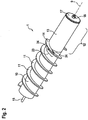
- Figs. 2 to 4 show in detail the structure of the press screw 1 according to the first embodiment.
- Fig. 2 shows the fully assembled state of the press screw 1.
- the press screw 1 is composed of a base core 10 with two screw spirals 11 and an attached wear element 12.
- Fig. 3 shows the press screw 1 without the wear element 12.
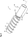
- Fig. 4 an unfinished state is shown in which the wear element 12 has not yet been fully plugged onto the base core 10.
- the Figs. 2 to 4 show that the base core 10 is divided into a first section 18 and a second section 19.
- the two helical screws 11 sit on the first section 18.
- the second section 19 has a smaller outer diameter than the first section 18.
- the wear element 12 is pushed onto the second section 19.
- the wear element 12 is composed of an additional core 13 and at least one spiral section 14 on the additional core 13. Both the base core 10 and the additional core 13 are tubular elements that are concentrically plugged onto one another along the axis 9.
- the torque from the transmission 7 is transmitted to the base core 10 via a holding element 15, also referred to as a tie rod or internal strut.
- the holding element 15 extends concentrically to the axis 9 through the base core 10 and the additional core 13.
- a disk 17 is placed on the additional core 13.
- a fitting surface 20 is provided on the second section 19. Furthermore, a first conical tube surface 21 on the base core 10 and a second conical tube surface 22 on the additional core 13 ensure an exact fit of the two components.
- the ends of the screw helix 11 and the screw helix section 14 are provided with a bevel 24.
- the additional core 13 has a plug portion 26. At this plug section 26 no worm helixes are provided. In this area, the solid plug forms inside the press screw separator 2.
- the screw spiral section 14 faces the plug area.
- Such a design of the overlap area 23 ensures that the torque can be reliably transmitted from the worm helix 11 to the worm helix section 14 via the overlap area.
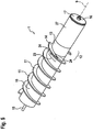
- Figures 5 to 9 show a second exemplary embodiment of the press screw 1.
- the wear element 12 is made much shorter than in the first exemplary embodiment.
- a clamping tube 27 is pushed onto the second section 19 of the base core 10 to form the plug area.
- FIG. 6 shows the base core 10 with the helical screw 11 without wear element 12 and without clamping tube 27.
- the wear element 12 is first attached in a shortened form. Thereupon takes place according to Fig. 8 attaching the clamping tube 27.
- the clamping tube 27 is fastened via the washer 17 and the nut 16.
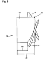
- Fig. 9 shows in detail the shortened wear element 12 according to the second embodiment.
- the design of the conical tube surfaces 21, 22 and the design of the screw spiral sections 14 correspond to the first Embodiment.
- corresponding conical tube surfaces can advantageously also be provided at the joint between the additional core 13 and the clamping tube 27.
- the wear element 12 has a first length 28.
- the clamping tube 27 extends over a second length 29.
- the second length 29 is advantageously significantly longer than the first length 28, so that the required plug area is available without helical screws. In the event of wear, only the relatively short wear element 12 has to be replaced.
- the clamping tube 27 can continue to be used.
- the first length 28 results from two areas: (i) The piece of the additional core 13 on which the two screw spiral sections 14 are arranged. These have opposite to the transport direction, to rest on the screw helix 11 from the Figure 7 protruding ends that serve to prevent rotation. And (ii) the piece of the additional core 13 with the third length 28a, on which there are no screw spiral sections. In practice, it has been shown that in the transport direction immediately behind the two wing ends on the diameter of the additional core 13, a high level of wear can be recorded.
- the third length 28a is preferably 10% to 50%, particularly preferably 15% to 30% of the outer diameter of the screw helices 11 or screw helix sections 14. In particular, the third length 28a is between 30 mm and 100 mm.
- press screw 1 To produce the press screw 1, it is also provided in particular that conventional press screws are turned off in the region of the second section 19. This makes it possible to attach the wear element 12 according to the invention.
Landscapes
- Engineering & Computer Science (AREA)
- Mechanical Engineering (AREA)
- Press Drives And Press Lines (AREA)
- Treatment Of Sludge (AREA)
- Filtration Of Liquid (AREA)
- Paper (AREA)
Priority Applications (2)
| Application Number | Priority Date | Filing Date | Title |
|---|---|---|---|
| SI201531615T SI3094479T1 (sl) | 2014-01-15 | 2015-01-12 | Stiskalni vijak stiskalnega vijačnega ločevalnika |
| PL15700220T PL3094479T3 (pl) | 2014-01-15 | 2015-01-12 | Ślimak tłoczący dla separatora ze ślimakiem tłoczącym |
Applications Claiming Priority (2)
| Application Number | Priority Date | Filing Date | Title |
|---|---|---|---|
| DE102014200577.9A DE102014200577B3 (de) | 2014-01-15 | 2014-01-15 | Pressschnecke, Pressschneckenseparator, Verschleißelement und Verfahren zum Herstellen einer Pressschnecke |
| PCT/EP2015/050395 WO2015107018A1 (de) | 2014-01-15 | 2015-01-12 | Pressschnecke für einen pressschneckenseparator |
Publications (2)
| Publication Number | Publication Date |
|---|---|
| EP3094479A1 EP3094479A1 (de) | 2016-11-23 |
| EP3094479B1 true EP3094479B1 (de) | 2021-04-14 |
Family
ID=52345243
Family Applications (1)
| Application Number | Title | Priority Date | Filing Date |
|---|---|---|---|
| EP15700220.5A Active EP3094479B1 (de) | 2014-01-15 | 2015-01-12 | Pressschnecke für einen pressschneckenseparator |
Country Status (7)
| Country | Link |
|---|---|
| EP (1) | EP3094479B1 (pl) |
| DE (1) | DE102014200577B3 (pl) |
| ES (1) | ES2880285T3 (pl) |
| HU (1) | HUE054807T2 (pl) |
| PL (1) | PL3094479T3 (pl) |
| SI (1) | SI3094479T1 (pl) |
| WO (1) | WO2015107018A1 (pl) |
Families Citing this family (1)
| Publication number | Priority date | Publication date | Assignee | Title |
|---|---|---|---|---|
| DE102021128199A1 (de) * | 2021-10-28 | 2023-05-04 | Vogelsang Gmbh & Co. Kg | Separatorvorrichtung zur Entwässerung feuchter Massen |
Citations (3)
| Publication number | Priority date | Publication date | Assignee | Title |
|---|---|---|---|---|
| GB310680A (en) * | 1928-05-23 | 1929-05-02 | Percy Vavasseur Appleby | Improvements in or relating to feed or pressure worms, applicable for use in oil-pressing apparatus or the like |
| DE554916C (de) * | 1930-09-25 | 1932-07-13 | Fried Krupp Grusonwerk Akt Ges | Schneckenpresse fuer feuchtes Gut mit hohler Schneckenwelle und Abfuehrung des OEls durch die Seiherwandung und die hohle Welle |
| DE2203331A1 (de) * | 1972-01-25 | 1973-08-02 | Miag Muehlenbau & Ind Gmbh | Presschnecke fuer die mechanische fluessigkeitsextraktion |
Family Cites Families (5)
| Publication number | Priority date | Publication date | Assignee | Title |
|---|---|---|---|---|
| GB966647A (en) * | 1961-07-05 | 1964-08-12 | Telegrafie & Telefonie | Device for changing the orientation or direction of movement of post cards, letters,forms and like flat articles |
| DE4444370A1 (de) * | 1994-12-14 | 1996-06-20 | Max Gutknecht | Vorrichtung zum thermischen, mechanischen, chemischen und/oder physikalischen Behandeln eines Produktes |
| DE29706744U1 (de) * | 1997-04-15 | 1998-05-20 | Hasenbein, Günter, Dipl.-Ing., 22946 Großensee | Schneckenelement für Schneckenpresse |
| DE102008021935B4 (de) * | 2008-05-02 | 2024-08-14 | Werkstoff + Funktion Grimmel Wassertechnik Gmbh | Schneckenpresse |
| DE202011004414U1 (de) * | 2011-03-22 | 2011-06-01 | Kun Sheng Machine Co., Ltd. | Entwässer- und Aufbereitungsmaschine |
-
2014
- 2014-01-15 DE DE102014200577.9A patent/DE102014200577B3/de active Active
-
2015
- 2015-01-12 EP EP15700220.5A patent/EP3094479B1/de active Active
- 2015-01-12 SI SI201531615T patent/SI3094479T1/sl unknown
- 2015-01-12 HU HUE15700220A patent/HUE054807T2/hu unknown
- 2015-01-12 WO PCT/EP2015/050395 patent/WO2015107018A1/de not_active Ceased
- 2015-01-12 ES ES15700220T patent/ES2880285T3/es active Active
- 2015-01-12 PL PL15700220T patent/PL3094479T3/pl unknown
Patent Citations (3)
| Publication number | Priority date | Publication date | Assignee | Title |
|---|---|---|---|---|
| GB310680A (en) * | 1928-05-23 | 1929-05-02 | Percy Vavasseur Appleby | Improvements in or relating to feed or pressure worms, applicable for use in oil-pressing apparatus or the like |
| DE554916C (de) * | 1930-09-25 | 1932-07-13 | Fried Krupp Grusonwerk Akt Ges | Schneckenpresse fuer feuchtes Gut mit hohler Schneckenwelle und Abfuehrung des OEls durch die Seiherwandung und die hohle Welle |
| DE2203331A1 (de) * | 1972-01-25 | 1973-08-02 | Miag Muehlenbau & Ind Gmbh | Presschnecke fuer die mechanische fluessigkeitsextraktion |
Also Published As
| Publication number | Publication date |
|---|---|
| SI3094479T1 (sl) | 2021-08-31 |
| EP3094479A1 (de) | 2016-11-23 |
| WO2015107018A1 (de) | 2015-07-23 |
| HUE054807T2 (hu) | 2021-09-28 |
| ES2880285T3 (es) | 2021-11-24 |
| PL3094479T3 (pl) | 2021-10-11 |
| DE102014200577B3 (de) | 2015-05-28 |
Similar Documents
| Publication | Publication Date | Title |
|---|---|---|
| DE102009000891B4 (de) | Verfahren und Gewindewerkzeug, jeweils zur Ausformung eines lnnengewindes an einem Grundkörper | |
| DE202018104413U1 (de) | Separator für Abwasserbehandlung mit beweglichem Siebkörper | |
| EP2754552B1 (de) | Pressschneckenseparator und Verfahren zum Betrieb des Pressschneckenseparators | |
| EP3094479B1 (de) | Pressschnecke für einen pressschneckenseparator | |
| EP3427937B1 (de) | Schnecke eines pressschneckenseparators | |
| DE202011105765U1 (de) | Siebanordnung für einen Pressschneckenseparator | |
| DE102004008477B4 (de) | Schraubverbindung | |
| EP2749335A1 (de) | Zweiteiliger Partikelfilter und Verfahren zu seiner Herstellung | |
| DE202012011864U1 (de) | Pressschneckenseparator | |
| DE602004006611T2 (de) | Stabsiebkorb zur Filtrierung von Fasersuspensionen und Verfahren zu dessen Herstellung | |
| EP2094391B1 (de) | Tragkorb einer siebzentrifuge | |
| AT14550U1 (de) | Schneckenpresse | |
| DE102014111661A1 (de) | Schwingungselement mit entkoppeltem Bauteil | |
| EP2474767B1 (de) | Verbindungselement für eine Leitungsanordnung | |
| EP2780158B1 (de) | Schneckenpresse | |
| EP0571750A1 (de) | Schneckenpresse | |
| DE102013000561B3 (de) | Pressschneckenseparator und Siebanordnung | |
| AT526355B1 (de) | Pressschneckenseparator mit modifizierter Pressschnecke | |
| EP3302952B1 (de) | Schneckenpresse | |
| WO2015121280A1 (de) | PRESSSCHNECKENSEPARATOR UND VERSCHLEIßRING | |
| DE102004033257B4 (de) | Elektrischer Motor | |
| AT15674U1 (de) | Schneckenpresse | |
| DE502012C (de) | Zentralschmiervorrichtung, insbesondere fuer Kraftfahrzeuge | |
| DE102017105615A1 (de) | Schneckenseparator mit einem Siebrohr | |
| DE102006043454B4 (de) | Band-Zugsicherungsklemme für einen Rohrverbindungsfitting |
Legal Events
| Date | Code | Title | Description |
|---|---|---|---|
| PUAI | Public reference made under article 153(3) epc to a published international application that has entered the european phase |
Free format text: ORIGINAL CODE: 0009012 |
|
| 17P | Request for examination filed |
Effective date: 20160504 |
|
| AK | Designated contracting states |
Kind code of ref document: A1 Designated state(s): AL AT BE BG CH CY CZ DE DK EE ES FI FR GB GR HR HU IE IS IT LI LT LU LV MC MK MT NL NO PL PT RO RS SE SI SK SM TR |
|
| AX | Request for extension of the european patent |
Extension state: BA ME |
|
| DAX | Request for extension of the european patent (deleted) | ||
| STAA | Information on the status of an ep patent application or granted ep patent |
Free format text: STATUS: EXAMINATION IS IN PROGRESS |
|
| 17Q | First examination report despatched |
Effective date: 20200218 |
|
| GRAP | Despatch of communication of intention to grant a patent |
Free format text: ORIGINAL CODE: EPIDOSNIGR1 |
|
| STAA | Information on the status of an ep patent application or granted ep patent |
Free format text: STATUS: GRANT OF PATENT IS INTENDED |
|
| GRAS | Grant fee paid |
Free format text: ORIGINAL CODE: EPIDOSNIGR3 |
|
| INTG | Intention to grant announced |
Effective date: 20210208 |
|
| GRAA | (expected) grant |
Free format text: ORIGINAL CODE: 0009210 |
|
| STAA | Information on the status of an ep patent application or granted ep patent |
Free format text: STATUS: THE PATENT HAS BEEN GRANTED |
|
| AK | Designated contracting states |
Kind code of ref document: B1 Designated state(s): AL AT BE BG CH CY CZ DE DK EE ES FI FR GB GR HR HU IE IS IT LI LT LU LV MC MK MT NL NO PL PT RO RS SE SI SK SM TR |
|
| REG | Reference to a national code |
Ref country code: GB Ref legal event code: FG4D Free format text: NOT ENGLISH |
|
| REG | Reference to a national code |
Ref country code: CH Ref legal event code: EP |
|
| REG | Reference to a national code |
Ref country code: DE Ref legal event code: R096 Ref document number: 502015014553 Country of ref document: DE |
|
| REG | Reference to a national code |
Ref country code: IE Ref legal event code: FG4D Free format text: LANGUAGE OF EP DOCUMENT: GERMAN |
|
| REG | Reference to a national code |
Ref country code: AT Ref legal event code: REF Ref document number: 1381971 Country of ref document: AT Kind code of ref document: T Effective date: 20210515 |
|
| REG | Reference to a national code |
Ref country code: RO Ref legal event code: EPE |
|
| REG | Reference to a national code |
Ref country code: NL Ref legal event code: FP |
|
| REG | Reference to a national code |
Ref country code: LT Ref legal event code: MG9D |
|
| REG | Reference to a national code |
Ref country code: SK Ref legal event code: T3 Ref document number: E 37659 Country of ref document: SK |
|
| REG | Reference to a national code |
Ref country code: HU Ref legal event code: AG4A Ref document number: E054807 Country of ref document: HU |
|
| PG25 | Lapsed in a contracting state [announced via postgrant information from national office to epo] |
Ref country code: BG Free format text: LAPSE BECAUSE OF FAILURE TO SUBMIT A TRANSLATION OF THE DESCRIPTION OR TO PAY THE FEE WITHIN THE PRESCRIBED TIME-LIMIT Effective date: 20210714 Ref country code: HR Free format text: LAPSE BECAUSE OF FAILURE TO SUBMIT A TRANSLATION OF THE DESCRIPTION OR TO PAY THE FEE WITHIN THE PRESCRIBED TIME-LIMIT Effective date: 20210414 Ref country code: LT Free format text: LAPSE BECAUSE OF FAILURE TO SUBMIT A TRANSLATION OF THE DESCRIPTION OR TO PAY THE FEE WITHIN THE PRESCRIBED TIME-LIMIT Effective date: 20210414 Ref country code: FI Free format text: LAPSE BECAUSE OF FAILURE TO SUBMIT A TRANSLATION OF THE DESCRIPTION OR TO PAY THE FEE WITHIN THE PRESCRIBED TIME-LIMIT Effective date: 20210414 |
|
| REG | Reference to a national code |
Ref country code: ES Ref legal event code: FG2A Ref document number: 2880285 Country of ref document: ES Kind code of ref document: T3 Effective date: 20211124 |
|
| PG25 | Lapsed in a contracting state [announced via postgrant information from national office to epo] |
Ref country code: GR Free format text: LAPSE BECAUSE OF FAILURE TO SUBMIT A TRANSLATION OF THE DESCRIPTION OR TO PAY THE FEE WITHIN THE PRESCRIBED TIME-LIMIT Effective date: 20210715 Ref country code: LV Free format text: LAPSE BECAUSE OF FAILURE TO SUBMIT A TRANSLATION OF THE DESCRIPTION OR TO PAY THE FEE WITHIN THE PRESCRIBED TIME-LIMIT Effective date: 20210414 Ref country code: IS Free format text: LAPSE BECAUSE OF FAILURE TO SUBMIT A TRANSLATION OF THE DESCRIPTION OR TO PAY THE FEE WITHIN THE PRESCRIBED TIME-LIMIT Effective date: 20210814 Ref country code: SE Free format text: LAPSE BECAUSE OF FAILURE TO SUBMIT A TRANSLATION OF THE DESCRIPTION OR TO PAY THE FEE WITHIN THE PRESCRIBED TIME-LIMIT Effective date: 20210414 Ref country code: RS Free format text: LAPSE BECAUSE OF FAILURE TO SUBMIT A TRANSLATION OF THE DESCRIPTION OR TO PAY THE FEE WITHIN THE PRESCRIBED TIME-LIMIT Effective date: 20210414 Ref country code: NO Free format text: LAPSE BECAUSE OF FAILURE TO SUBMIT A TRANSLATION OF THE DESCRIPTION OR TO PAY THE FEE WITHIN THE PRESCRIBED TIME-LIMIT Effective date: 20210714 Ref country code: PT Free format text: LAPSE BECAUSE OF FAILURE TO SUBMIT A TRANSLATION OF THE DESCRIPTION OR TO PAY THE FEE WITHIN THE PRESCRIBED TIME-LIMIT Effective date: 20210816 |
|
| REG | Reference to a national code |
Ref country code: DE Ref legal event code: R097 Ref document number: 502015014553 Country of ref document: DE |
|
| PG25 | Lapsed in a contracting state [announced via postgrant information from national office to epo] |
Ref country code: SM Free format text: LAPSE BECAUSE OF FAILURE TO SUBMIT A TRANSLATION OF THE DESCRIPTION OR TO PAY THE FEE WITHIN THE PRESCRIBED TIME-LIMIT Effective date: 20210414 Ref country code: EE Free format text: LAPSE BECAUSE OF FAILURE TO SUBMIT A TRANSLATION OF THE DESCRIPTION OR TO PAY THE FEE WITHIN THE PRESCRIBED TIME-LIMIT Effective date: 20210414 Ref country code: DK Free format text: LAPSE BECAUSE OF FAILURE TO SUBMIT A TRANSLATION OF THE DESCRIPTION OR TO PAY THE FEE WITHIN THE PRESCRIBED TIME-LIMIT Effective date: 20210414 |
|
| PLBE | No opposition filed within time limit |
Free format text: ORIGINAL CODE: 0009261 |
|
| STAA | Information on the status of an ep patent application or granted ep patent |
Free format text: STATUS: NO OPPOSITION FILED WITHIN TIME LIMIT |
|
| 26N | No opposition filed |
Effective date: 20220117 |
|
| PG25 | Lapsed in a contracting state [announced via postgrant information from national office to epo] |
Ref country code: IS Free format text: LAPSE BECAUSE OF FAILURE TO SUBMIT A TRANSLATION OF THE DESCRIPTION OR TO PAY THE FEE WITHIN THE PRESCRIBED TIME-LIMIT Effective date: 20210814 Ref country code: AL Free format text: LAPSE BECAUSE OF FAILURE TO SUBMIT A TRANSLATION OF THE DESCRIPTION OR TO PAY THE FEE WITHIN THE PRESCRIBED TIME-LIMIT Effective date: 20210414 |
|
| PG25 | Lapsed in a contracting state [announced via postgrant information from national office to epo] |
Ref country code: MC Free format text: LAPSE BECAUSE OF FAILURE TO SUBMIT A TRANSLATION OF THE DESCRIPTION OR TO PAY THE FEE WITHIN THE PRESCRIBED TIME-LIMIT Effective date: 20210414 |
|
| REG | Reference to a national code |
Ref country code: CH Ref legal event code: PL |
|
| GBPC | Gb: european patent ceased through non-payment of renewal fee |
Effective date: 20220112 |
|
| PG25 | Lapsed in a contracting state [announced via postgrant information from national office to epo] |
Ref country code: LU Free format text: LAPSE BECAUSE OF NON-PAYMENT OF DUE FEES Effective date: 20220112 Ref country code: GB Free format text: LAPSE BECAUSE OF NON-PAYMENT OF DUE FEES Effective date: 20220112 |
|
| PG25 | Lapsed in a contracting state [announced via postgrant information from national office to epo] |
Ref country code: LI Free format text: LAPSE BECAUSE OF NON-PAYMENT OF DUE FEES Effective date: 20220131 Ref country code: CH Free format text: LAPSE BECAUSE OF NON-PAYMENT OF DUE FEES Effective date: 20220131 |
|
| PG25 | Lapsed in a contracting state [announced via postgrant information from national office to epo] |
Ref country code: IE Free format text: LAPSE BECAUSE OF NON-PAYMENT OF DUE FEES Effective date: 20220112 |
|
| REG | Reference to a national code |
Ref country code: AT Ref legal event code: MM01 Ref document number: 1381971 Country of ref document: AT Kind code of ref document: T Effective date: 20220112 |
|
| PG25 | Lapsed in a contracting state [announced via postgrant information from national office to epo] |
Ref country code: AT Free format text: LAPSE BECAUSE OF NON-PAYMENT OF DUE FEES Effective date: 20220112 |
|
| PG25 | Lapsed in a contracting state [announced via postgrant information from national office to epo] |
Ref country code: MK Free format text: LAPSE BECAUSE OF FAILURE TO SUBMIT A TRANSLATION OF THE DESCRIPTION OR TO PAY THE FEE WITHIN THE PRESCRIBED TIME-LIMIT Effective date: 20210414 Ref country code: CY Free format text: LAPSE BECAUSE OF FAILURE TO SUBMIT A TRANSLATION OF THE DESCRIPTION OR TO PAY THE FEE WITHIN THE PRESCRIBED TIME-LIMIT Effective date: 20210414 |
|
| PG25 | Lapsed in a contracting state [announced via postgrant information from national office to epo] |
Ref country code: MT Free format text: LAPSE BECAUSE OF FAILURE TO SUBMIT A TRANSLATION OF THE DESCRIPTION OR TO PAY THE FEE WITHIN THE PRESCRIBED TIME-LIMIT Effective date: 20210414 |
|
| PGFP | Annual fee paid to national office [announced via postgrant information from national office to epo] |
Ref country code: DE Payment date: 20250131 Year of fee payment: 11 |
|
| PGFP | Annual fee paid to national office [announced via postgrant information from national office to epo] |
Ref country code: RO Payment date: 20250109 Year of fee payment: 11 |
|
| PGFP | Annual fee paid to national office [announced via postgrant information from national office to epo] |
Ref country code: ES Payment date: 20250214 Year of fee payment: 11 |
|
| PGFP | Annual fee paid to national office [announced via postgrant information from national office to epo] |
Ref country code: BE Payment date: 20250121 Year of fee payment: 11 Ref country code: SI Payment date: 20250108 Year of fee payment: 11 |
|
| PGFP | Annual fee paid to national office [announced via postgrant information from national office to epo] |
Ref country code: FR Payment date: 20250122 Year of fee payment: 11 Ref country code: PL Payment date: 20250107 Year of fee payment: 11 |
|
| PGFP | Annual fee paid to national office [announced via postgrant information from national office to epo] |
Ref country code: SK Payment date: 20250110 Year of fee payment: 11 Ref country code: IT Payment date: 20250131 Year of fee payment: 11 |
|
| PG25 | Lapsed in a contracting state [announced via postgrant information from national office to epo] |
Ref country code: TR Free format text: LAPSE BECAUSE OF FAILURE TO SUBMIT A TRANSLATION OF THE DESCRIPTION OR TO PAY THE FEE WITHIN THE PRESCRIBED TIME-LIMIT Effective date: 20210414 |
|
| PGFP | Annual fee paid to national office [announced via postgrant information from national office to epo] |
Ref country code: CZ Payment date: 20251230 Year of fee payment: 12 |
|
| PGFP | Annual fee paid to national office [announced via postgrant information from national office to epo] |
Ref country code: NL Payment date: 20260121 Year of fee payment: 12 |
|
| PGFP | Annual fee paid to national office [announced via postgrant information from national office to epo] |
Ref country code: HU Payment date: 20260113 Year of fee payment: 12 |