EP3093609A1 - Startsystem für einen lenkflugkörper sowie lenkflugkörper für ein derartiges startsystem - Google Patents
Startsystem für einen lenkflugkörper sowie lenkflugkörper für ein derartiges startsystem Download PDFInfo
- Publication number
- EP3093609A1 EP3093609A1 EP16169297.5A EP16169297A EP3093609A1 EP 3093609 A1 EP3093609 A1 EP 3093609A1 EP 16169297 A EP16169297 A EP 16169297A EP 3093609 A1 EP3093609 A1 EP 3093609A1
- Authority
- EP
- European Patent Office
- Prior art keywords
- guided missile
- missile
- firing pin
- launch
- cartridge
- Prior art date
- Legal status (The legal status is an assumption and is not a legal conclusion. Google has not performed a legal analysis and makes no representation as to the accuracy of the status listed.)
- Granted
Links
Images

Classifications
-
- F—MECHANICAL ENGINEERING; LIGHTING; HEATING; WEAPONS; BLASTING
- F42—AMMUNITION; BLASTING
- F42C—AMMUNITION FUZES; ARMING OR SAFETY MEANS THEREFOR
- F42C19/00—Details of fuzes
- F42C19/08—Primers; Detonators
- F42C19/0819—Primers or igniters for the initiation of rocket motors, i.e. pyrotechnical aspects thereof
-
- F—MECHANICAL ENGINEERING; LIGHTING; HEATING; WEAPONS; BLASTING
- F41—WEAPONS
- F41F—APPARATUS FOR LAUNCHING PROJECTILES OR MISSILES FROM BARRELS, e.g. CANNONS; LAUNCHERS FOR ROCKETS OR TORPEDOES; HARPOON GUNS
- F41F3/00—Rocket or torpedo launchers
- F41F3/04—Rocket or torpedo launchers for rockets
- F41F3/042—Rocket or torpedo launchers for rockets the launching apparatus being used also as a transport container for the rocket
-
- F—MECHANICAL ENGINEERING; LIGHTING; HEATING; WEAPONS; BLASTING
- F41—WEAPONS
- F41F—APPARATUS FOR LAUNCHING PROJECTILES OR MISSILES FROM BARRELS, e.g. CANNONS; LAUNCHERS FOR ROCKETS OR TORPEDOES; HARPOON GUNS
- F41F3/00—Rocket or torpedo launchers
- F41F3/04—Rocket or torpedo launchers for rockets
- F41F3/045—Rocket or torpedo launchers for rockets adapted to be carried and used by a person, e.g. bazookas
-
- F—MECHANICAL ENGINEERING; LIGHTING; HEATING; WEAPONS; BLASTING
- F41—WEAPONS
- F41F—APPARATUS FOR LAUNCHING PROJECTILES OR MISSILES FROM BARRELS, e.g. CANNONS; LAUNCHERS FOR ROCKETS OR TORPEDOES; HARPOON GUNS
- F41F3/00—Rocket or torpedo launchers
- F41F3/04—Rocket or torpedo launchers for rockets
- F41F3/052—Means for securing the rocket in the launching apparatus
Definitions
- the present invention relates to a guided missile launch system. Furthermore, the invention relates to a guided missile for use in such a missile launch system.
- the guided missile launch system is particularly shoulder-based and thus portable for a single user.
- the object is achieved by the features of the independent claim.
- a missile launch system comprising a launch tube and a handle.
- the launch tube has a steering missile space, which is designed to receive a missile.
- the starting pipe has a cartridge chamber, which is designed to receive a maneuvering cartridge.
- both the guided missile space and the cartridge space have a connection to an environment of the launch tube.
- the guided missile space and the cartridge space are completely separated from each other. Ignition of the maneuver cartridge thus does not lead to an ignition of the missile.
- the handle is anmontierbar, wherein the handle is also separable from the launch tube at any time.
- the handle has a striker system for igniting the maneuver cartridge.
- the guided missile launch system has increased safety in handling. If the starting pipe is separated from the handle, an accidental ignition of the maneuver cartridge is not possible because the associated firing pin system is present in the separate handle.
- the starting pipe has an opening in which a firing pin element is arranged.
- the firing pin protrudes into the missile space.
- the opening of the launch tube thus connects the steering missile space with an environment of the launch tube.
- the firing pin element advantageously the opening is completely closed.
- the engagement of the firing pin element in the steering missile space makes it possible to engage the firing pin element in an ignition opening of the guided missile. Since the firing pin element thus engages both in the opening of the launch tube and in the ignition opening of the missile, an axial centering of the opening of the launch tube and the ignition opening of the missile takes place.
- the missile thus has a predefined orientation within the launch tube.
- the firing pin member has a collar over which the firing pin member is fixed within the launch tube.
- a complete implementation of the firing pin element is thus prevented by the opening of the starting pipe. This prevents the risk of accidental ignition of the missile.
- the collar is designed as a tear-off. If a sufficient force is applied to the firing pin element, the collar fails, as a result of which the firing pin element can be completely transferred from the opening of the launch tube into the firing opening of the guided missile. Within the firing opening of the guided missile, the firing pin element can finally initiate an ignition of the guided missile.
- the handle has a gas channel.
- the gas passage of the maneuver cartridge space is connected to the firing pin member when the handle is mounted on the launch tube.
- a gas pressure is created within the gas passage which exerts a resultant force on the striker element.
- a displacement of the firing pin element takes place in the ignition opening of the guided missile, so that the firing pin element ignites the guided missile.
- the gas passage is disposed inside the grip, ignition of the maneuver cartridge in the case where the grip is not mounted on the launch tube does not result in displacement of the striker member because the gas passage is absent. In this case, only the gas pressure from the maneuver cartridge would be delivered to an environment of the missile launch system. It can be seen that thus the reliability and safety in handling the missile launch system are significantly increased.
- the guided missile launch system has an additional element.
- a gas channel is attached in the additional element.
- the additional element is particularly advantageous movably mounted on the handle and in particular swung out of the handle or swiveled into the handle.
- Operational safety is therefore increased in two stages. If the handle is separated from the starting pipe, it is not possible to ignite the maneuver cartridge due to the lack of firing pin system. Nevertheless, if the maneuver cartridge ignited inadvertently, so there is no connection to the missile space, so that the ignition of the maneuver cartridge has no effect on the missile itself. Only with a combination of handle and launch tube ignition of the maneuver cartridge is possible.
- the launch tube preferably has an additional locking element.
- the additional locking element of the missile is lockable in the launch tube of the missile launch system.
- a further manual locking is provided, whereby the missile is held securely and reliably within the missile space.
- a maneuver cartridge is permanently installed.
- the maneuver cartridge is not removable by a user. This ensures that the maneuver cartridge is always present, so that a lack of operational capability of the missile launch system is excluded due to a missing maneuver cartridge. Also, an unintentional ignition of the maneuver cartridge is difficult within the launch tube, so there is no risk that the maneuver cartridge is ignited accidentally.
- the invention further relates to a guided missile for use in a guided missile launch system as previously described.
- the guided missile has an ignition opening.
- a firing pin element of the guided missile launch system is insertable.
- the missile is fixable in a launch tube of the missile launch system.
- the firing pin element therefore advantageously has the task of keeping the guided missile within the launch tube of the guided missile launch system in a predefined orientation and simultaneously locking it. The lock can only be released when the firing pin element is fully inserted into the ignition opening, whereby the missile is ignited.
- the ignition opening leads to a thermal battery of the missile.
- the ignition opening leads to a primer of the thermal battery. In this way it is possible that with the firing pin element on the primer of the thermal battery is beatable. Once the firing pin element strikes the primer cap, the thermal battery is ignited, energizing the missile. This leads to a start of the missile from the guided missile launch system.
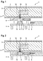
- FIG. 1 schematically shows a guided missile launch system 1 according to an embodiment of the invention.
- the guided missile launch system 1 comprises a launch tube 2 and a handle 7.
- the handle 7 is separated from the starting pipe 2.
- FIG. 2 shows the guided missile launch system 1 from FIG. 1 , wherein the handle 7 is mounted on the starting pipe 2.
- the guided missile launch system 1 is particularly suitable for launching shoulder-mounted missiles 4.
- the launch tube 2 serves as a logistic package for the guided missile and to launch the missile. 4
- the handle 7 is in particular connected only to launch the missile 4 with the launch tube 2 and is used to handle the missile launch system 1, the securing of the missile 4 and the initiation of the ignition process.
- the guided missile 4 is mounted in the launch tube 2 and locked and secured by two independent locking mechanisms.
- a first locking mechanism is present such that the guided missile 4 is manually locked to the launch tube.
- a second locking mechanism consists in a firing pin element 9, which is arranged both within an opening of the starting pipe 2 and within an ignition opening 10 of the guided missile 4.
- the ignition opening 10 serves as an interface of the missile for initiating and thus for firing the missile. 4
- the initiation of the guided missile 4 takes place by the targeted application of a arranged in a thermal battery 13 of the missile 4 Anzündhütchens 15 by the firing pin element 9.
- the firing pin member 9 must be accelerated to pitch on the primer 15. This is initiated by a maneuver cartridge 6.
- the maneuvering cartridge 6 is arranged within a cartridge chamber 5 of the starting pipe 2.
- the cartridge chamber 5 is separated from the guided missile space 3.
- the cartridge chamber 5 has an opening, so that the cartridge chamber 5 is opened to an environment of the starting pipe 2 out.
- the maneuvering cartridge 6 is advantageously arranged fixedly within the cartridge chamber 5, so that removal of the maneuvering cartridge 6 by a user of the guided missile launching system 1 is not possible.
- the handle 7 Only by inserting the handle 7 in the launch tube 2 of the maneuver cartridge chamber 5 is connected to the firing pin member 9.
- the handle 7 has a gas channel 12.
- the gas channel 12 connects the cartridge chamber 5 with the missile space 3 only when the handle is mounted on the launch tube 2. If the handle 7 is mounted on the starting pipe 2, then the maneuvering cartridge 6 can be ignited in order to generate an overpressure within the gas channel 12. This overpressure within the gas channel 12 finally leads to an acceleration of the firing pin element 9.
- a conventional striker system 8 is present.
- a striker system 8 may for example be installed in handguns.
- the firing pin element 8 is completely integrated within the grip piece 7, so that the firing pin system 8 can be separated from the launch tube 2 together with the grip piece 7. In this way, the product safety is substantially increased, since an unintentional ignition of the maneuver cartridge 6 is prevented. Only by mounting the handle 7 on the Starting pipe 2, the firing pin system 8 is aligned axially to the maneuver cartridge 6 to allow ignition of the maneuver cartridge 6. At the same time established by the insertion of the handle 7 of the gas channel 12 between the cartridge chamber 5 and firing pin member 9 so that an ignition of the maneuver cartridge 6 leads to an acceleration of the firing pin member 9.
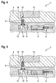
- FIG. 3 a detail view of the guided missile launch system 1 is shown.
- the guided missile launch system 1 is shown such that the grip 7 is mounted on the launch tube 2.
- the firing pin element 9 engages in the ignition opening 10 of the guided missile 4.
- This ignition opening 10 is aligned axially with an opening within the starting pipe 2, so that the firing pin element 9 is inserted in alignment both in the opening of the starting pipe 2 and in the ignition opening 10 of the guided missile 4.
- the firing pin element 9 In order to prevent the firing pin element 9 from being displaced unintentionally out of its position, the firing pin element 9 has a collar 11 which rests against the launch tube 2 outside the guided-body space 3. About a locking ring 14 of the collar 11 is fixed. Thus, a movement of the firing pin member 9 is prevented.
- the firing pin member 9 therefore serves as a Verrieglung for the missile 4, since the at least partially engaging the firing pin member 9 in the ignition opening 10 prevents displacement of the missile 4 within the missile space 3 of the launch tube 2. This locking can be achieved only by igniting the maneuver cartridge 6, since this ignition leads to a displacement of the firing pin member 9, whereby the firing pin member 9 is disposed completely within the ignition opening 10.
- the collar 11 is formed as a tear-off. If the gas pressure inside the gas channel 12 is increased by igniting the maneuver cartridge 6, this leads to a tearing off of the collar 11, as a result of which the firing pin element 9 becomes displaceable. Due to the pressure within the gas channel 12, therefore, an acceleration of the firing pin element 9 takes place in the ignition opening 10 of the guided missile 4 into it. This case is in FIG. 4 shown.
- FIG. 4 the firing pin system 8 was triggered, whereby the maneuver cartridge 6 was ignited. This is analogous to the firing of a handgun instead.
- the maneuver cartridge 6 By igniting the maneuver cartridge 6, an overpressure within the gas channel 12 is generated. This overpressure acts on the firing pin element 9. As soon as the overpressure reaches a predefined pressure, the collar 11 of the firing pin element 9 fails FIG. 5 shown.
Landscapes
- Engineering & Computer Science (AREA)
- General Engineering & Computer Science (AREA)
- Aiming, Guidance, Guns With A Light Source, Armor, Camouflage, And Targets (AREA)
Abstract
Description
- Die vorliegende Erfindung betrifft ein Lenkflugkörper-Startsystem. Weiterhin betrifft die Erfindung einen Lenkflugkörper zur Verwendung in einem derartigen Lenkflugkörper-Startsystem. Das Lenkflugkörper-Startsystem ist insbesondere schultergestützt und damit für einen einzelnen Benutzer portabel ausgestaltet.
- Aus dem Stand der Technik sind Startrohre für Lenkflugkörper bekannt, die ein Benutzer schultergestützt verwenden kann. Dabei besteht die Gefahr, dass eine unbeabsichtigte Zündung erfolgt oder eine Verriegelung des Lenkflugkörpers innerhalb des Startrohres unbeabsichtigt gelöst wird. In beiden Fällen kommt es zu einem ungewollten Austreten des Lenkflugkörpers aus dem Startrohr, was zumindest für den Benutzer eine hohe Gefahr darstellt. Außerdem besteht bei derartigen Startsystemen ein erhöhter Aufwand bezüglich Lagerung und Transport.
- Es ist daher Aufgabe der Erfindung, ein Lenkflugkörper-Startsystem bereitzustellen, das bei einfacher und kostengünstiger Herstellung und Montage eine sichere Handhabung des Lenkflugkörpers ermöglicht.
- Gelöst wird die Aufgabe durch die Merkmale des unabhängigen Anspruchs. Somit wird die Aufgabe gelöst durch ein Lenkflugkörper-Startsystem, umfassend ein Startrohr und ein Griffstück. Das Startrohr weist einen Lenkflugkörperraum auf, der zur Aufnahme eines Lenkflugkörpers ausgebildet ist. Weiterhin weist das Startrohr einen Patronenraum auf, der zur Aufnahme einer Manöverpatrone ausgebildet ist. Insbesondere ist vorgesehen, dass sowohl der Lenkflugkörperraum als auch der Patronenraum eine Verbindung zu einer Umgebung des Startrohrs aufweisen. Insbesondere ist vorgesehen, dass der Lenkflugkörperraum und der Patronenraum vollständig voneinander getrennt sind. Eine Zündung der Manöverpatrone führt somit nicht zu einer Zündung des Lenkflugkörpers. An das Startrohr ist das Griffstück anmontierbar, wobei das Griffstück ebenso jederzeit von dem Startrohr trennbar ist. Das Griffstück weist ein Schlagbolzensystem zum Zünden der Manöverpatrone auf. Somit ist ersichtlich, dass das Lenkflugkörper-Startsystem eine erhöhte Sicherheit in Bezug auf die Handhabung aufweist. Wird das Startrohr von dem Griffstück getrennt, so ist eine versehentliche Zündung der Manöverpatrone nicht möglich, da das zugehörige Schlagbolzensystem in dem getrennten Griffstück vorhanden ist.
- Die Unteransprüche haben bevorzugte Weiterbildungen der Erfindung zum Inhalt.
- Vorteilhafterweise weist das Startrohr eine Öffnung auf, in der ein Schlagbolzenelement angeordnet ist. Dabei ragt das Schlagbolzenelement in den Lenkflugkörperraum. Die Öffnung des Startrohrs verbindet somit den Lenkflugkörperraum mit einer Umgebung des Startrohrs. Durch das Einsetzen des Schlagbolzenelements ist vorteilhafterweise die Öffnung vollständig verschlossen. Durch das Eingreifen des Schlagbolzenelements in den Lenkflugkörperraum ist ermöglicht, dass mit dem Schlagbolzenelement in eine Zündungsöffnung des Lenkflugkörpers eingreifbar ist. Da das Schlagbolzenelement somit sowohl in die Öffnung des Startrohrs als auch in die Zündungsöffnung des Lenkflugkörpers eingreift, findet eine axiale Zentrierung der Öffnung des Startrohrs und der Zündungsöffnung des Lenkflugkörpers statt. Der Lenkflugkörper hat somit eine vordefinierte Ausrichtung innerhalb des Startrohrs.
- Besonders vorteilhaft weist das Schlagbolzenelement einen Kragen auf, über den das Schlagbolzenelement innerhalb des Startrohrs fixiert ist. Insbesondere ist somit ein vollständiges Durchführen des Schlagbolzenelements durch die Öffnung des Startrohrs verhindert. Dies verhindert die Gefahr einer unbeabsichtigten Zündung des Lenkflugkörpers.
- Weiterhin ist besonders vorteilhaft vorgesehen, dass der Kragen als Abreißelement ausgebildet ist. Wird eine ausreichende Kraft auf das Schlagbolzenelement aufgebracht, so versagt der Kragen, wodurch das Schlagbolzenelement von der Öffnung des Startrohrs vollständig in die Zündungsöffnung des Lenkflugkörpers überführbar ist. Innerhalb der Zündungsöffnung des Lenkflugkörpers kann das Schlagbolzenelement schließlich eine Zündung des Lenkflugkörpers initiieren.
- Mit dem Schlagbolzenelement ist vorteilhafterweise der Lenkflugkörper in dem Startrohr verriegelbar. Somit ist durch das Schlagbolzenelement eine Verriegelung gegeben. Diese Verriegelung ist nicht unabsichtlich lösbar, sondern kann lediglich durch ein vollständiges Verschieben des Schlagbolzenelements in die Zündungsöffnung des Lenkflugkörpers gelöst werden. Somit wird die Verriegelung durch das Schlagbolzenelement erst dann gelöst, wenn der Lenkflugkörper gezündet werden soll. Ein unbeabsichtigtes Lösen ist damit verhindert.
- Vorteilhafterweise weist das Griffstück einen Gaskanal auf. Durch den Gaskanal ist der Manöverpatronenraum mit dem Schlagbolzenelement verbunden, wenn das Griffstück an das Startrohr montiert ist. Sollte in dem Fall, dass das Griffstück an das Startrohr montiert ist, die Manöverpatrone gezündet werden, so wird innerhalb des Gaskanals ein Gasdruck aufgebaut, der eine resultierende Kraft auf das Schlagbolzenelement ausübt. In diesem Fall ist vorteilhafterweise vorgesehen, dass eine Verschiebung des Schlagbolzenelements in die Zündungsöffnung des Lenkflugkörpers erfolgt, sodass das Schlagbolzenelement den Lenkflugkörper zündet. Da der Gaskanal innerhalb des Griffstücks angeordnet ist, führt eine Zündung der Manöverpatrone in dem Fall, in dem das Griffstück nicht an dem Startrohr montiert ist, auch nicht zu einer Verschiebung des Schlagbolzenelements, da der Gaskanal nicht vorhanden ist. In diesem Fall würde lediglich der Gasdruck aus der Manöverpatrone an eine Umgebung des Lenkflugkörper-Startsystems abgegeben. Es ist ersichtlich, dass somit die Betriebssicherheit und die Sicherheit bei der Handhabung des Lenkflugkörper-Startsystems deutlich erhöht sind.
- Alternativ weist das Lenkflugkörper-Startsystem ein Zusatzelement auf. In dem Zusatzelement ist ein Gaskanal angebracht. Durch den Gaskanal ist der Manöverpatronenraum mit dem Schlagbolzenelement verbunden, wenn das Griffstück an das Startrohr montiert ist und das Zusatzelement in das Griffstück oder in das Startrohr eingesetzt ist. Das Zusatzelement ist besonders vorteilhaft an dem Griffstück beweglich befestigt und insbesondere aus dem Griffstück ausschwenkbar oder in das Griffstück einschwenkbar. Somit ist die Betriebssicherheit sowie die Sicherheit bei der Handhabung des Lenkflugkörper-Startsystems weiter erhöht, da bei Fehlen des Zusatzelements auch ein an das Startrohr montiertes Griffstück nicht zu einer Zündung der Manöverpatrone führen kann.
- Die Betriebssicherheit ist daher zweistufig erhöht. Sollte das Griffstück von dem Startrohr getrennt sein, so ist eine Zündung der Manöverpatrone aufgrund des fehlenden Schlagbolzensystems nicht möglich. Wird dennoch die Manöverpatrone aus Unachtsamkeit gezündet, so besteht keine Verbindung zu dem Lenkflugkörperraum, sodass die Zündung der Manöverpatrone keine Auswirkung auf den Lenkflugkörper selbst hat. Erst bei einer Verbindung von Griffstück und Startrohr ist eine Zündung der Manöverpatrone möglich.
- Das Startrohr weist bevorzugt ein zusätzliches Verriegelungselement auf. Mit dem zusätzlichen Verriegelungselement ist der Lenkflugkörper in dem Startrohr des Lenkflugkörper-Startsystems verriegelbar. Somit ist eine weitere manuelle Verriegelung vorhanden, wodurch der Lenkflugkörper sicher und zuverlässig innerhalb des Lenkflugkörperraums gehalten ist.
- In dem Patronenraum ist vorteilhafterweise eine Manöverpatrone fest verbaut. Auf diese Weise ist die Manöverpatrone nicht von einem Benutzer entnehmbar. Somit ist sichergestellt, dass die Manöverpatrone stets vorhanden ist, sodass eine mangelnde Einsatzfähigkeit des Lenkflugkörper-Startsystems aufgrund einer fehlenden Manöverpatrone ausgeschlossen ist. Auch ist innerhalb des Startrohrs eine unbeabsichtigte Zündung der Manöverpatrone erschwert, sodass nicht die Gefahr besteht, dass die Manöverpatrone unbeabsichtigt gezündet wird.
- Die Erfindung betrifft weiterhin einen Lenkflugkörper zur Verwendung in einem Lenkflugkörper-Startsystem wie zuvor beschrieben. Der Lenkflugkörper weist dabei eine Zündungsöffnung auf. In der Zündungsöffnung ist ein Schlagbolzenelement des Lenkflugkörper-Startsystems einführbar. Auf diese Weise ist der Lenkflugkörper in einem Startrohr des Lenkflugkörper-Startsystems fixierbar. Das Schlagbolzenelement hat daher vorteilhafterweise die Aufgabe, den Lenkflugkörper innerhalb des Startrohrs des Lenkflugkörper-Startsystems in einer vordefinierten Ausrichtung zu halten und gleichzeitig zu verriegeln. Die Verriegelung ist erst dann lösbar, wenn das Schlagbolzenelement vollständig in die Zündungsöffnung eingeführt wird, wodurch der Lenkflugkörper gezündet wird.
- In einer bevorzugten Ausführungsform führt die Zündungsöffnung zu einer Thermalbatterie des Lenkflugkörpers. Besonders vorteilhaft führt die Zündungsöffnung zu einem Anzündhütchen der Thermalbatterie. Auf diese Weise ist ermöglich, dass mit dem Schlagbolzenelement auf das Anzündhütchen der Thermalbatterie schlagbar ist. Sobald das Schlagbolzenelement auf das Anzündhütchen aufschlägt, wird die Thermalbatterie gezündet, wodurch der Lenkflugkörper mit Energie versorgt wird. Dies führt zu einem Starten des Lenkflugkörpers aus dem Lenkflugkörper-Startsystem.
- Die Erfindung wird nun anhand eines Ausführungsbeispiels unter Berücksichtigung der beigefügten Zeichnungen im Detail beschreiben. In den Zeichnungen ist:
- Fig. 1
- eine schematische Abbildung eines Lenkflugkörper-Startsystems gemäß einem Ausführungsbeispiel der Erfindung mit getrenntem Startrohr und Griffstück,
- Fig. 2
- eine schematische Abbildung des Lenkflugkörper-Startsystems gemäß dem Ausführungsbeispiel der Erfindung mit montiertem Griffstück und Startrohr,
- Fig. 3
- eine schematische Abbildung eines Details des Lenkflugkörper-Startsystems gemäß dem Ausführungsbeispiel der Erfindung,
- Fig. 4
- eine erste schematische Detailansicht des Lenkflugkörper-Startsystems gemäß dem Ausführungsbeispiel der Erfindung während eines Zündvorgangs des Lenkflugkörpers, und
- Fig. 5
- eine zweite schematische Detailansicht des Lenkflugkörper-Startsystems gemäß dem Ausführungsbeispiel der Erfindung während einer Zündung des Lenkflugkörpers.
-
Figur 1 zeigt schematisch ein Lenkflugkörper-Startsystem 1 gemäß einem Ausführungsbeispiel der Erfindung. Das Lenkflugkörper-Startsystem 1 umfasst ein Startrohr 2 und in ein Griffstück 7. InFigur 1 ist das Griffstück 7 von dem Startrohr 2 getrennt.Figur 2 zeigt das Lenkflugkörper-Startsystem 1 ausFigur 1 , wobei das Griffstück 7 an das Startrohr 2 anmontiert ist. - Das Lenkflugkörper-Startsystem 1 ist insbesondere für den Start von schultergestützten Lenkflugkörpern 4 geeignet. Dabei dient das Startrohr 2 als logistische Verpackung für den Lenkflugkörper sowie zum Abschuss des Lenkflugkörpers 4.
- Das Griffstück 7 ist insbesondere lediglich zum Abschuss des Lenkflugkörpers 4 mit dem Startrohr 2 verbunden und dient der Handhabung des Lenkflugkörper-Startsystems 1, dem Sichern des Lenkflugkörpers 4 und der Initiierung des Zündvorgangs. Der Lenkflugkörper 4 ist in dem Startrohr 2 gelagert und durch zwei unabhängige Verriegelungsmechanismen verriegelt und gesichert. Dabei ist ein erster Verriegelungsmechanismus derart vorhanden, dass der Lenkflugkörper 4 manuell mit dem Startrohr verriegelt ist. Dies ist aus dem Stand der Technik bekannt und daher in den Figuren nicht gezeigt. Ein zweiter Verriegelungsmechanismus besteht in einem Schlagbolzenelement 9, das sowohl innerhalb einer Öffnung des Startrohrs 2 als auch innerhalb einer Zündungsöffnung 10 des Lenkflugkörpers 4 angeordnet ist. Die Zündungsöffnung 10 dient dabei als Schnittstelle des Lenkflugkörpers zum Initiieren und damit zum Abschießen des Lenkflugkörpers 4.
- Die Initiierung des Lenkflugkörpers 4 geschieht durch die gezielte Beaufschlagung eines in einer Thermalbatterie 13 des Lenkflugkörpers 4 angeordneten Anzündhütchens 15 durch das Schlagbolzenelement 9. Dazu muss das Schlagbolzenelement 9 beschleunigt werden, um auf das Anzündhütchen 15 aufzuschlagen. Dies wird durch eine Manöverpatrone 6 initiiert.
- Die Manöverpatrone 6 ist innerhalb eines Patronenraums 5 des Startrohrs 2 angeordnet. Der Patronenraum 5 ist von dem Lenkflugkörperraum 3 getrennt. Dabei weist der Patronenraum 5 eine Öffnung auf, sodass der Patronenraum 5 zu einer Umgebung des Startrohrs 2 hin geöffnet ist. Die Manöverpatrone 6 ist vorteilhafterweise fest innerhalb des Patronenraums 5 angeordnet, sodass ein Entnehmen der Manöverpatrone 6 durch einen Benutzer des Lenkflugkörper-Startsystems 1 nicht möglich ist.
- Erst durch Einsetzen des Griffstücks 7 in das Startrohr 2 wird der Manöverpatronenraum 5 mit dem Schlagbolzenelement 9 verbunden. Dazu weist das Griffstück 7 einen Gaskanal 12 auf. Der Gaskanal 12 verbindet den Patronenraum 5 mit dem Lenkflugkörperraum 3 nur dann, wenn das Griffstück an das Startrohr 2 anmontiert ist. Ist das Griffstück 7 an das Startrohr 2 anmontiert, so kann die Manöverpatrone 6 gezündet werden, um einen Überdruck innerhalb des Gaskanals 12 zu erzeugen. Dieser Überdruck innerhalb des Gaskanals 12 führt schließlich zu einer Beschleunigung des Schlagbolzenelements 9.
- Zum Initiieren der Manöverpatrone 6 ist ein konventionelles Schlagbolzensystem 8 vorhanden. Ein solches Schlagbolzensystem 8 kann beispielsweise auch in Faustfeuerwaffen verbaut sein. Das Schlagbolzenelement 8 ist vollständig innerhalb des Griffstücks 7 integriert, sodass das Schlagbolzensystem 8 zusammen mit dem Griffstück 7 von dem Startrohr 2 getrennt werden kann. Auf diese Weise ist die Produktsicherheit wesentlich erhöht, da eine unbeabsichtigte Zündung der Manöverpatrone 6 verhindert ist. Erst durch die Montage des Griffstücks 7 an dem Startrohr 2 wird das Schlagbolzensystem 8 axial zur Manöverpatrone 6 ausgerichtet, um eine Zündung der Manöverpatrone 6 zu ermöglichen. Gleichzeitig wird durch das Einsetzen des Griffstücks 7 der Gaskanal 12 zwischen Manöverpatronenraum 5 und Schlagbolzenelement 9 etabliert, sodass eine Zündung der Manöverpatrone 6 zu einer Beschleunigung des Schlagbolzenelements 9 führt.
- In
Figur 3 ist eine Detailansicht des Lenkflugkörper-Startsystems 1 dargestellt. InFigur 3 ist das Lenkflugkörper-Startsystem 1 derart dargestellt, dass das Griffstück 7 an dem Startrohr 2 montiert ist. - Es ist ersichtlich, dass das Schlagbolzenelement 9 in die Zündungsöffnung 10 des Lenkflugkörpers 4 eingreift. Diese Zündungsöffnung 10 ist axial zu einer Öffnung innerhalb des Startrohrs 2 ausgerichtet, sodass das Schlagbolzenelement 9 fluchtend sowohl in die Öffnung des Startrohrs 2 als auch in die Zündungsöffnung 10 des Lenkflugkörpers 4 eingesetzt ist.
- Um zu verhindern, dass das Schlagbolzenelement 9 aus seiner Position unbeabsichtigt verschoben wird, weist das Schlagbolzenelement 9 einen Kragen 11 auf, der an dem Startrohr 2 außerhalb des Lenkflugkörperraumes 3 anliegt. Über einen Sicherungsring 14 ist der Kragen 11 fixiert. Somit ist ein Bewegen des Schlagbolzenelements 9 verhindert. Das Schlagbolzenelement 9 dient daher als Verrieglung für den Lenkflugkörper 4, da das zumindest teilweise Eingreifen des Schlagbolzenelements 9 in die Zündungsöffnung 10 ein Verschieben des Lenkflugkörpers 4 innerhalb des Lenkflugkörperraums 3 des Startrohrs 2 verhindert. Diese Verriegelung kann erst durch ein Zünden der Manöverpatrone 6 gelöst werden, da dieses Zünden zu einem Verschieben des Schlagbolzenelements 9 führt, wodurch das Schlagbolzenelement 9 vollständig innerhalb der Zündungsöffnung 10 angeordnet ist.
- Der Kragen 11 ist als Abreißelement ausgebildet. Wird durch ein Zünden der Manöverpatrone 6 der Gasdruck innerhalb des Gaskanals 12 erhöht, so führt dies zu einem Abreißen des Kragens 11, wodurch das Schlagbolzenelement 9 verschiebbar wird. Durch den Druck innerhalb des Gaskanals 12 findet daher eine Beschleunigung des Schlagbolzelements 9 in die Zündungsöffnung 10 des Lenkflugkörpers 4 hinein statt. Dieser Fall ist in
Figur 4 gezeigt. - In
Figur 4 wurde das Schlagbolzensystem 8 ausgelöst, wodurch die Manöverpatrone 6 gezündet wurde. Dies findet analog zum Abfeuern einer Faustfeuerwaffe statt. Durch das Zünden der Manöverpatrone 6 wird ein Überdruck innerhalb des Gaskanals 12 erzeugt. Dieser Überdruck wirkt auf das Schlagbolzenelement 9. Sobald der Überdruck einen vordefinierten Druck erreicht, versagt der Kragen 11 des Schlagbolzenelements 9. Dieser Fall ist inFigur 5 gezeigt. - In
Figur 5 hat der Kragen 11 des Schlagbolzenelements 9 versagt, sodass das Schlagbolzenelement 9 durch den Gasdruck innerhalb des Gaskanals 12 beschleunigt wird. Durch die Beschleunigung des Schlagbolzenelements 9 wird dieses vollständig in die Zündungsöffnung 10 des Lenkflugkörpers 4 eingeschoben. Somit ist einerseits die Verriegelung zwischen Startrohr 2 und Lenkflugkörper 4, die durch das Schlagbolzenelement 9 etabliert wurde, gelöst, andererseits schlägt das Schlagbolzenelement 9 auf das Anzündhütchen 15 der Thermalbatterie 13 des Lenkflugkörpers 4 auf. Auf diese Weise wird die Thermalbatterie 13 aktiviert, wodurch der Lenkflugkörper 4 mit elektrischer Energie versorgt wird. Dies führt zu einem Hochfahren der Elektronik des Lenkflugkörpers, wodurch die Funktionen des Lenkflugkörpers gestartet werden. Dies führt vorteilhafterweise zu einem Abschuss des Lenkflugkörpers aus dem Startrohr 2. - Die Erfindung hat weiterhin die folgenden Vorteile:
- A) Systeminitiierung unter Verwendung eines Gasgenerators in Form einer Manöverpatrone, welche sich aufgrund ihrer Bauform zum einen durch eine voll integrierte Anzündkette und zum anderen durch eine hohe Robustheit gegenüber Umweltwirkungen auszeichnet.
- B) Systemische Trennung von primären Initiator und Energieträger beziehungsweise Anzündkette, bei gleichzeitiger Unterbrechung des Gaskanals durch segmentalen Aufbau, wobei ein Gaskanalsegment im Griffstück verbleibt und den Gaskanal derart öffnet, dass in getrennter Konfiguration keine Verdämmung und somit kein Gasdruckanstieg im Gaskanalsystem ermöglicht ist. Dies trägt wesentlich zur Robustifizierung des Systems und einer Maximierung der Produktsicherheit bei. Im vorliegenden Fall ist der primäre Initiator vorteilhafterweise eine Schlagbolzenkinematik im Griffstück, während der Energieträger beziehungsweise die Anzündkette die Manöverpatronen darstellt.
- C) Integration eines Bolzenelements mit Doppelfunktion, welches formschlüssig im Gesamtsystem verbaut ist und den Lenkflugkörper axial wie auch radial im Abschussrohr verriegelt und nach Initiierung des Gesamtsystems seine Funktion und Form gemäß seiner zweiten Bestimmung als Schlagbolzenelement verändert, indem bei Erreichen eines am Boden des Schlagbolzenelements anstehenden Mindestgasdrucks ein geometrischer Absatz oder Ansatz, insbesondere ein Kragen, vom Schlagbolzenelement abreißt, sodass der Formschluss aufgehoben wird und der Bolzen zwecks Initiierung in Richtung einer internen Anzündkette des Lenkflugkörpers beschleunigt wird, sodass im Zuge der Beschleunigung auch die Verriegelung des Lenkflugkörpers im Gesamtsystem gelöst wird.
- Neben der vorstehenden schriftlichen Beschreibung der Erfindung wird zu deren ergänzender Offenbarung hiermit explizit auf die zeichnerische Darstellung der Erfindung in den
Fig. 1 bis 5 Bezug genommen. -
- 1 Lenkflugkörper-Startsystem
- 2 Startrohr
- 3 Lenkflugkörperraum
- 4 Lenkflugkörper
- 5 Patronenraum
- 6 Manöverpatrone
- 7 Griffstück
- 8 Schlagbolzensystem
- 9 Schlagbolzenelement
- 10 Zündungsöffnung
- 11 Kragen
- 12 Gaskanal
- 13 Thermalbatterie
- 14 Sicherungsring
Claims (11)
- Lenkflugkörper-Startsystem (1) umfassend ein Startrohr (2) mit einem Lenkflugkörperraum (3) zum Aufnehmen eines Lenkflugkörpers (4) und mit einem Patronenraum (5) zur Aufnahme einer Manöverpatrone (6), und einem an das Startrohr (2) anmontierbaren und von dem Startrohr (2) trennbaren Griffstück (7) mit einem Schlagbolzensystem (8) zum Zünden der Manöverpatrone (6).
- Lenkflugkörper-Startsystem (1) nach Anspruch 1, dadurch gekennzeichnet, dass das Startrohr (2) eine Öffnung aufweist, in der ein Schlagbolzenelement (9) angeordnet ist, wobei das Schlagbolzenelement (9) in den Lenkflugkörperraum (3) ragt, sodass mit dem Schlagbolzenelement (9) in eine Zündungsöffnung (10) des Lenkflugkörpers (4) eingreifbar ist.
- Lenkflugkörper-Startsystem (1) nach Anspruch 2, dadurch gekennzeichnet, dass das Schlagbolzenelement (9) einen Kragen (11) aufweist, über den das Schlagbolzenelement (9) im Startrohr (2) fixierbar ist.
- Lenkflugkörper-Startsystem (1) nach Anspruch 3, dadurch gekennzeichnet, dass der Kragen (11) als Abreißelement ausgebildet ist.
- Lenkflugkörper-Startsystem (1) nach einem der Ansprüche 2 bis 4, dadurch gekennzeichnet, dass mit dem Schlagbolzenelement (9) der Lenkflugköper (4) im Startrohr (2) verriegelbar ist.
- Lenkflugkörper-Startsystem (1) nach einem der Ansprüche 2 bis 5, dadurch gekennzeichnet, dass das Griffstück (7) einen Gaskanal (12) aufweist, der den Manöverpatronenraum (5) mit dem Schlagbolzenelement (9) verbindet, wenn das Griffstück (7) an das Startrohr (2) montiert ist.
- Lenkflugkörper-Startsystem (1) nach einem der Ansprüche 2 bis 5, gekennzeichnet durch ein Zusatzelement, wobei das Zusatzelement einen Gaskanal (12) aufweist, der den Manöverpatronenraum (5) mit dem Schlagbolzenelement (9) verbindet, wenn das Griffstück (7) an das Startrohr (2) montiert ist und das Zusatzelement in das Startrohr (2) oder das Griffstück (7) eingesetzt ist.
- Lenkflugkörper-Startsystem (1) nach einem der vorhergehenden Ansprüche, dadurch gekennzeichnet, dass das Startrohr 2 ein Verriegelungselement aufweist, mit dem der Lenkflugkörper (4) in dem Lenkflugkörperraum (3) verriegelbar ist.
- Lenkflugkörper-Startsystem (1) nach einem der vorhergehenden Ansprüche, dadurch gekennzeichnet, dass in dem Patronenraum (5) eine Manöverpatrone (6) fest verbaut ist, sodass die Manöverpatrone (6) durch einen Benutzer nicht entnehmbar ist.
- Lenkflugkörper (4) zur Verwendung in einem Lenkflugkörper-Startsystem (1) nach einem der vorhergehenden Ansprüche, dadurch gekennzeichnet, dass der Lenkflugkörper (4) eine Zündungsöffnung (10) aufweist, in die ein Schlagbolzenelement (9) des Lenkflugkörper-Startsystems (1) einführbar ist, um den Lenkflugkörper (4) in einem Startrohr (2) des Lenkflugkörper-Startsystems (1) zu fixieren.
- Lenkflugkörper (4) nach Anspruch 10, dadurch gekennzeichnet, dass die Zündungsöffnungen (10) zu einer Thermalbatterie (13) des Lenkflugkörpers (4) führt, sodass das Schlagbolzenelement (9) auf ein Anzündhütchen (15) der Thermalbatterie (13) schlagbar ist.
Priority Applications (1)
| Application Number | Priority Date | Filing Date | Title |
|---|---|---|---|
| PL16169297T PL3093609T3 (pl) | 2015-05-12 | 2016-05-12 | System startowy pocisku naprowadzanego oraz pocisk naprowadzany dla takiego systemu startowego |
Applications Claiming Priority (2)
| Application Number | Priority Date | Filing Date | Title |
|---|---|---|---|
| DE102015005954 | 2015-05-12 | ||
| DE102015009823.3A DE102015009823B4 (de) | 2015-05-12 | 2015-07-28 | Startsystem für einen Lenkflugkörper sowie Lenkflugkörper für ein derartiges Startsystem |
Publications (2)
| Publication Number | Publication Date |
|---|---|
| EP3093609A1 true EP3093609A1 (de) | 2016-11-16 |
| EP3093609B1 EP3093609B1 (de) | 2018-09-26 |
Family
ID=56119285
Family Applications (1)
| Application Number | Title | Priority Date | Filing Date |
|---|---|---|---|
| EP16169297.5A Active EP3093609B1 (de) | 2015-05-12 | 2016-05-12 | Startsystem für einen lenkflugkörper sowie lenkflugkörper für ein derartiges startsystem |
Country Status (2)
| Country | Link |
|---|---|
| EP (1) | EP3093609B1 (de) |
| PL (1) | PL3093609T3 (de) |
Citations (6)
| Publication number | Priority date | Publication date | Assignee | Title |
|---|---|---|---|---|
| US1311021A (en) * | 1918-05-25 | 1919-07-22 | Lawrence Y Spear | Fixed ammunition for non-recoil guns. |
| FR1206603A (fr) * | 1949-06-14 | 1960-02-10 | Tech De Rech S Ind & Mecanique | Matériel toutes missions pour lancement de projectiles auto-propulsés |
| DE1107561B (de) * | 1959-11-12 | 1961-05-25 | Diehl Fa | Vorrichtung zum Zuenden einer Geschosstreibladung |
| DE3130963A1 (de) * | 1981-08-05 | 1983-03-03 | Heckler & Koch Gmbh, 7238 Oberndorf | Abzugsvorrichtung fuer eine panzerfaust |
| DE8508837U1 (de) * | 1985-03-25 | 1985-07-04 | Nico-Pyrotechnik Hanns-Jürgen Diederichs GmbH & Co KG, 2077 Trittau | Panzerabwehrwaffe |
| EP0372431A1 (de) * | 1988-12-09 | 1990-06-13 | NICO-PYROTECHNIK Hanns-Jürgen Diederichs GmbH & Co. KG | Anzündvorrichtung, insbesondere für eine Treibladung einer rückstossfreien Panzerabwehrübungswaffe |
-
2016
- 2016-05-12 EP EP16169297.5A patent/EP3093609B1/de active Active
- 2016-05-12 PL PL16169297T patent/PL3093609T3/pl unknown
Patent Citations (6)
| Publication number | Priority date | Publication date | Assignee | Title |
|---|---|---|---|---|
| US1311021A (en) * | 1918-05-25 | 1919-07-22 | Lawrence Y Spear | Fixed ammunition for non-recoil guns. |
| FR1206603A (fr) * | 1949-06-14 | 1960-02-10 | Tech De Rech S Ind & Mecanique | Matériel toutes missions pour lancement de projectiles auto-propulsés |
| DE1107561B (de) * | 1959-11-12 | 1961-05-25 | Diehl Fa | Vorrichtung zum Zuenden einer Geschosstreibladung |
| DE3130963A1 (de) * | 1981-08-05 | 1983-03-03 | Heckler & Koch Gmbh, 7238 Oberndorf | Abzugsvorrichtung fuer eine panzerfaust |
| DE8508837U1 (de) * | 1985-03-25 | 1985-07-04 | Nico-Pyrotechnik Hanns-Jürgen Diederichs GmbH & Co KG, 2077 Trittau | Panzerabwehrwaffe |
| EP0372431A1 (de) * | 1988-12-09 | 1990-06-13 | NICO-PYROTECHNIK Hanns-Jürgen Diederichs GmbH & Co. KG | Anzündvorrichtung, insbesondere für eine Treibladung einer rückstossfreien Panzerabwehrübungswaffe |
Also Published As
| Publication number | Publication date |
|---|---|
| PL3093609T3 (pl) | 2019-03-29 |
| EP3093609B1 (de) | 2018-09-26 |
Similar Documents
| Publication | Publication Date | Title |
|---|---|---|
| DE69009427T2 (de) | Verriegelungsvorrichtung. | |
| DE10205043B4 (de) | Aus einem Rohr zu verschließender Flugkörper mit überkalibrigem Leitwerk | |
| EP3230682B1 (de) | Zündersystem für handgranaten | |
| DE2648267A1 (de) | Zuendvorrichtung fuer geschoss, rakete o.dgl. | |
| DE2119574A1 (de) | Sicherheitsperkussionszuendvorrichtung nach dem traegheitsprinzip fuer geschosse und raketengeschosse | |
| EP3093609B1 (de) | Startsystem für einen lenkflugkörper sowie lenkflugkörper für ein derartiges startsystem | |
| DE102015009823B4 (de) | Startsystem für einen Lenkflugkörper sowie Lenkflugkörper für ein derartiges Startsystem | |
| DE1578033A1 (de) | Raketenabschusseinrichtung | |
| DE2400947C3 (de) | Sicherungs- und Entsicherungsvorrichtung für GeschoDzünder | |
| DE102018008106B4 (de) | Geschoss mit einer Führungsbandanordnung | |
| DE2448495A1 (de) | Raketen-antriebsvorrichtung | |
| EP2739931B1 (de) | Manöverpatroneneinrichtung und hierfür geeignete selbstlade-feuerwaffe | |
| EP2339285B1 (de) | Granate und Granatabschussvorrichtung | |
| DE3140044A1 (de) | Abzugsgriff | |
| EP1397635B1 (de) | Zünder für eine handgranate | |
| DE102017001196B4 (de) | Zünder eines Flugkörpers und Verfahren zum Entsichern eines Zünders eines Flugkörpers | |
| EP0267407B1 (de) | Sicherungseinrichtung für einen Zünder eines Gefechtskopfes | |
| DE10001886A1 (de) | Aus einer Rohrwaffe verschießbares Geschoss | |
| DE2017923A1 (de) | Signaleinrichtung mit einer in einem Abfeuerungsrohr angeordneten Rakete | |
| EP3336482B1 (de) | Verfahren und vorrichtung zu sicherung und entsicherung eines wurfkörpers | |
| EP2144033B1 (de) | Zünder für ein Geschoss | |
| DE2854865C2 (de) | Sicherungsvorrichtung für Bombenzünder mit Windrad | |
| DE3620524A1 (de) | Anzuendeinrichtung fuer raketen | |
| DE1578033C (de) | Raketenabschußeinrichtung | |
| EP2010859B1 (de) | Aufklärungssonde |
Legal Events
| Date | Code | Title | Description |
|---|---|---|---|
| PUAI | Public reference made under article 153(3) epc to a published international application that has entered the european phase |
Free format text: ORIGINAL CODE: 0009012 |
|
| AK | Designated contracting states |
Kind code of ref document: A1 Designated state(s): AL AT BE BG CH CY CZ DE DK EE ES FI FR GB GR HR HU IE IS IT LI LT LU LV MC MK MT NL NO PL PT RO RS SE SI SK SM TR |
|
| AX | Request for extension of the european patent |
Extension state: BA ME |
|
| STAA | Information on the status of an ep patent application or granted ep patent |
Free format text: STATUS: REQUEST FOR EXAMINATION WAS MADE |
|
| 17P | Request for examination filed |
Effective date: 20170516 |
|
| RBV | Designated contracting states (corrected) |
Designated state(s): AL AT BE BG CH CY CZ DE DK EE ES FI FR GB GR HR HU IE IS IT LI LT LU LV MC MK MT NL NO PL PT RO RS SE SI SK SM TR |
|
| GRAP | Despatch of communication of intention to grant a patent |
Free format text: ORIGINAL CODE: EPIDOSNIGR1 |
|
| STAA | Information on the status of an ep patent application or granted ep patent |
Free format text: STATUS: GRANT OF PATENT IS INTENDED |
|
| RIC1 | Information provided on ipc code assigned before grant |
Ipc: F42C 19/08 20060101AFI20180411BHEP Ipc: F41F 3/045 20060101ALI20180411BHEP Ipc: F41F 3/042 20060101ALN20180411BHEP Ipc: F41F 3/052 20060101ALI20180411BHEP |
|
| RIC1 | Information provided on ipc code assigned before grant |
Ipc: F42C 19/08 20060101AFI20180417BHEP Ipc: F41F 3/045 20060101ALI20180417BHEP Ipc: F41F 3/042 20060101ALN20180417BHEP Ipc: F41F 3/052 20060101ALI20180417BHEP |
|
| INTG | Intention to grant announced |
Effective date: 20180502 |
|
| GRAS | Grant fee paid |
Free format text: ORIGINAL CODE: EPIDOSNIGR3 |
|
| GRAA | (expected) grant |
Free format text: ORIGINAL CODE: 0009210 |
|
| STAA | Information on the status of an ep patent application or granted ep patent |
Free format text: STATUS: THE PATENT HAS BEEN GRANTED |
|
| AK | Designated contracting states |
Kind code of ref document: B1 Designated state(s): AL AT BE BG CH CY CZ DE DK EE ES FI FR GB GR HR HU IE IS IT LI LT LU LV MC MK MT NL NO PL PT RO RS SE SI SK SM TR |
|
| REG | Reference to a national code |
Ref country code: GB Ref legal event code: FG4D Free format text: NOT ENGLISH |
|
| REG | Reference to a national code |
Ref country code: CH Ref legal event code: EP |
|
| REG | Reference to a national code |
Ref country code: AT Ref legal event code: REF Ref document number: 1046526 Country of ref document: AT Kind code of ref document: T Effective date: 20181015 |
|
| REG | Reference to a national code |
Ref country code: IE Ref legal event code: FG4D Free format text: LANGUAGE OF EP DOCUMENT: GERMAN |
|
| REG | Reference to a national code |
Ref country code: DE Ref legal event code: R096 Ref document number: 502016002059 Country of ref document: DE |
|
| REG | Reference to a national code |
Ref country code: NL Ref legal event code: MP Effective date: 20180926 |
|
| PG25 | Lapsed in a contracting state [announced via postgrant information from national office to epo] |
Ref country code: GR Free format text: LAPSE BECAUSE OF FAILURE TO SUBMIT A TRANSLATION OF THE DESCRIPTION OR TO PAY THE FEE WITHIN THE PRESCRIBED TIME-LIMIT Effective date: 20181227 Ref country code: FI Free format text: LAPSE BECAUSE OF FAILURE TO SUBMIT A TRANSLATION OF THE DESCRIPTION OR TO PAY THE FEE WITHIN THE PRESCRIBED TIME-LIMIT Effective date: 20180926 Ref country code: SE Free format text: LAPSE BECAUSE OF FAILURE TO SUBMIT A TRANSLATION OF THE DESCRIPTION OR TO PAY THE FEE WITHIN THE PRESCRIBED TIME-LIMIT Effective date: 20180926 Ref country code: LT Free format text: LAPSE BECAUSE OF FAILURE TO SUBMIT A TRANSLATION OF THE DESCRIPTION OR TO PAY THE FEE WITHIN THE PRESCRIBED TIME-LIMIT Effective date: 20180926 Ref country code: RS Free format text: LAPSE BECAUSE OF FAILURE TO SUBMIT A TRANSLATION OF THE DESCRIPTION OR TO PAY THE FEE WITHIN THE PRESCRIBED TIME-LIMIT Effective date: 20180926 Ref country code: NO Free format text: LAPSE BECAUSE OF FAILURE TO SUBMIT A TRANSLATION OF THE DESCRIPTION OR TO PAY THE FEE WITHIN THE PRESCRIBED TIME-LIMIT Effective date: 20181226 Ref country code: BG Free format text: LAPSE BECAUSE OF FAILURE TO SUBMIT A TRANSLATION OF THE DESCRIPTION OR TO PAY THE FEE WITHIN THE PRESCRIBED TIME-LIMIT Effective date: 20181226 |
|
| REG | Reference to a national code |
Ref country code: ES Ref legal event code: FG2A Ref document number: 2698251 Country of ref document: ES Kind code of ref document: T3 Effective date: 20190201 |
|
| REG | Reference to a national code |
Ref country code: LT Ref legal event code: MG4D |
|
| PG25 | Lapsed in a contracting state [announced via postgrant information from national office to epo] |
Ref country code: AL Free format text: LAPSE BECAUSE OF FAILURE TO SUBMIT A TRANSLATION OF THE DESCRIPTION OR TO PAY THE FEE WITHIN THE PRESCRIBED TIME-LIMIT Effective date: 20180926 Ref country code: LV Free format text: LAPSE BECAUSE OF FAILURE TO SUBMIT A TRANSLATION OF THE DESCRIPTION OR TO PAY THE FEE WITHIN THE PRESCRIBED TIME-LIMIT Effective date: 20180926 Ref country code: HR Free format text: LAPSE BECAUSE OF FAILURE TO SUBMIT A TRANSLATION OF THE DESCRIPTION OR TO PAY THE FEE WITHIN THE PRESCRIBED TIME-LIMIT Effective date: 20180926 |
|
| PG25 | Lapsed in a contracting state [announced via postgrant information from national office to epo] |
Ref country code: EE Free format text: LAPSE BECAUSE OF FAILURE TO SUBMIT A TRANSLATION OF THE DESCRIPTION OR TO PAY THE FEE WITHIN THE PRESCRIBED TIME-LIMIT Effective date: 20180926 Ref country code: IS Free format text: LAPSE BECAUSE OF FAILURE TO SUBMIT A TRANSLATION OF THE DESCRIPTION OR TO PAY THE FEE WITHIN THE PRESCRIBED TIME-LIMIT Effective date: 20190126 Ref country code: RO Free format text: LAPSE BECAUSE OF FAILURE TO SUBMIT A TRANSLATION OF THE DESCRIPTION OR TO PAY THE FEE WITHIN THE PRESCRIBED TIME-LIMIT Effective date: 20180926 Ref country code: NL Free format text: LAPSE BECAUSE OF FAILURE TO SUBMIT A TRANSLATION OF THE DESCRIPTION OR TO PAY THE FEE WITHIN THE PRESCRIBED TIME-LIMIT Effective date: 20180926 Ref country code: CZ Free format text: LAPSE BECAUSE OF FAILURE TO SUBMIT A TRANSLATION OF THE DESCRIPTION OR TO PAY THE FEE WITHIN THE PRESCRIBED TIME-LIMIT Effective date: 20180926 |
|
| PG25 | Lapsed in a contracting state [announced via postgrant information from national office to epo] |
Ref country code: PT Free format text: LAPSE BECAUSE OF FAILURE TO SUBMIT A TRANSLATION OF THE DESCRIPTION OR TO PAY THE FEE WITHIN THE PRESCRIBED TIME-LIMIT Effective date: 20190126 Ref country code: SM Free format text: LAPSE BECAUSE OF FAILURE TO SUBMIT A TRANSLATION OF THE DESCRIPTION OR TO PAY THE FEE WITHIN THE PRESCRIBED TIME-LIMIT Effective date: 20180926 Ref country code: SK Free format text: LAPSE BECAUSE OF FAILURE TO SUBMIT A TRANSLATION OF THE DESCRIPTION OR TO PAY THE FEE WITHIN THE PRESCRIBED TIME-LIMIT Effective date: 20180926 |
|
| REG | Reference to a national code |
Ref country code: DE Ref legal event code: R097 Ref document number: 502016002059 Country of ref document: DE |
|
| PG25 | Lapsed in a contracting state [announced via postgrant information from national office to epo] |
Ref country code: DK Free format text: LAPSE BECAUSE OF FAILURE TO SUBMIT A TRANSLATION OF THE DESCRIPTION OR TO PAY THE FEE WITHIN THE PRESCRIBED TIME-LIMIT Effective date: 20180926 |
|
| PLBE | No opposition filed within time limit |
Free format text: ORIGINAL CODE: 0009261 |
|
| STAA | Information on the status of an ep patent application or granted ep patent |
Free format text: STATUS: NO OPPOSITION FILED WITHIN TIME LIMIT |
|
| 26N | No opposition filed |
Effective date: 20190627 |
|
| PG25 | Lapsed in a contracting state [announced via postgrant information from national office to epo] |
Ref country code: SI Free format text: LAPSE BECAUSE OF FAILURE TO SUBMIT A TRANSLATION OF THE DESCRIPTION OR TO PAY THE FEE WITHIN THE PRESCRIBED TIME-LIMIT Effective date: 20180926 |
|
| REG | Reference to a national code |
Ref country code: CH Ref legal event code: PL |
|
| PG25 | Lapsed in a contracting state [announced via postgrant information from national office to epo] |
Ref country code: MC Free format text: LAPSE BECAUSE OF FAILURE TO SUBMIT A TRANSLATION OF THE DESCRIPTION OR TO PAY THE FEE WITHIN THE PRESCRIBED TIME-LIMIT Effective date: 20180926 Ref country code: LI Free format text: LAPSE BECAUSE OF NON-PAYMENT OF DUE FEES Effective date: 20190531 Ref country code: CH Free format text: LAPSE BECAUSE OF NON-PAYMENT OF DUE FEES Effective date: 20190531 |
|
| REG | Reference to a national code |
Ref country code: BE Ref legal event code: MM Effective date: 20190531 |
|
| PG25 | Lapsed in a contracting state [announced via postgrant information from national office to epo] |
Ref country code: LU Free format text: LAPSE BECAUSE OF NON-PAYMENT OF DUE FEES Effective date: 20190512 |
|
| PG25 | Lapsed in a contracting state [announced via postgrant information from national office to epo] |
Ref country code: TR Free format text: LAPSE BECAUSE OF FAILURE TO SUBMIT A TRANSLATION OF THE DESCRIPTION OR TO PAY THE FEE WITHIN THE PRESCRIBED TIME-LIMIT Effective date: 20180926 |
|
| PG25 | Lapsed in a contracting state [announced via postgrant information from national office to epo] |
Ref country code: IE Free format text: LAPSE BECAUSE OF NON-PAYMENT OF DUE FEES Effective date: 20190512 |
|
| PG25 | Lapsed in a contracting state [announced via postgrant information from national office to epo] |
Ref country code: BE Free format text: LAPSE BECAUSE OF NON-PAYMENT OF DUE FEES Effective date: 20190531 |
|
| PG25 | Lapsed in a contracting state [announced via postgrant information from national office to epo] |
Ref country code: CY Free format text: LAPSE BECAUSE OF FAILURE TO SUBMIT A TRANSLATION OF THE DESCRIPTION OR TO PAY THE FEE WITHIN THE PRESCRIBED TIME-LIMIT Effective date: 20180926 |
|
| PG25 | Lapsed in a contracting state [announced via postgrant information from national office to epo] |
Ref country code: MT Free format text: LAPSE BECAUSE OF FAILURE TO SUBMIT A TRANSLATION OF THE DESCRIPTION OR TO PAY THE FEE WITHIN THE PRESCRIBED TIME-LIMIT Effective date: 20180926 Ref country code: HU Free format text: LAPSE BECAUSE OF FAILURE TO SUBMIT A TRANSLATION OF THE DESCRIPTION OR TO PAY THE FEE WITHIN THE PRESCRIBED TIME-LIMIT; INVALID AB INITIO Effective date: 20160512 |
|
| PG25 | Lapsed in a contracting state [announced via postgrant information from national office to epo] |
Ref country code: MK Free format text: LAPSE BECAUSE OF FAILURE TO SUBMIT A TRANSLATION OF THE DESCRIPTION OR TO PAY THE FEE WITHIN THE PRESCRIBED TIME-LIMIT Effective date: 20180926 |
|
| REG | Reference to a national code |
Ref country code: AT Ref legal event code: MM01 Ref document number: 1046526 Country of ref document: AT Kind code of ref document: T Effective date: 20210512 |
|
| PG25 | Lapsed in a contracting state [announced via postgrant information from national office to epo] |
Ref country code: AT Free format text: LAPSE BECAUSE OF NON-PAYMENT OF DUE FEES Effective date: 20210512 |
|
| P01 | Opt-out of the competence of the unified patent court (upc) registered |
Effective date: 20230510 |
|
| PGFP | Annual fee paid to national office [announced via postgrant information from national office to epo] |
Ref country code: PL Payment date: 20250505 Year of fee payment: 10 Ref country code: DE Payment date: 20250528 Year of fee payment: 10 |
|
| PGFP | Annual fee paid to national office [announced via postgrant information from national office to epo] |
Ref country code: ES Payment date: 20250627 Year of fee payment: 10 Ref country code: GB Payment date: 20250527 Year of fee payment: 10 |
|
| PGFP | Annual fee paid to national office [announced via postgrant information from national office to epo] |
Ref country code: IT Payment date: 20250527 Year of fee payment: 10 |
|
| PGFP | Annual fee paid to national office [announced via postgrant information from national office to epo] |
Ref country code: FR Payment date: 20250528 Year of fee payment: 10 |