EP3092666B1 - Glueless light emitting device with phosphor converter - Google Patents
Glueless light emitting device with phosphor converter Download PDFInfo
- Publication number
- EP3092666B1 EP3092666B1 EP14837008.3A EP14837008A EP3092666B1 EP 3092666 B1 EP3092666 B1 EP 3092666B1 EP 14837008 A EP14837008 A EP 14837008A EP 3092666 B1 EP3092666 B1 EP 3092666B1
- Authority
- EP
- European Patent Office
- Prior art keywords
- light emitting
- wavelength conversion
- substrate
- transparent substrate
- film
- Prior art date
- Legal status (The legal status is an assumption and is not a legal conclusion. Google has not performed a legal analysis and makes no representation as to the accuracy of the status listed.)
- Active
Links
- OAICVXFJPJFONN-UHFFFAOYSA-N Phosphorus Chemical compound [P] OAICVXFJPJFONN-UHFFFAOYSA-N 0.000 title description 24
- 239000000758 substrate Substances 0.000 claims description 71
- 238000006243 chemical reaction Methods 0.000 claims description 50
- 239000000463 material Substances 0.000 claims description 42
- 238000000034 method Methods 0.000 claims description 31
- 238000003475 lamination Methods 0.000 claims description 13
- 239000011521 glass Substances 0.000 claims description 12
- 239000003292 glue Substances 0.000 claims description 9
- 239000000853 adhesive Substances 0.000 claims description 4
- 230000001070 adhesive effect Effects 0.000 claims description 4
- 239000010980 sapphire Substances 0.000 claims description 3
- 229910052594 sapphire Inorganic materials 0.000 claims description 3
- 229920005573 silicon-containing polymer Polymers 0.000 claims description 3
- 238000010030 laminating Methods 0.000 claims 4
- 239000002131 composite material Substances 0.000 description 13
- 230000003287 optical effect Effects 0.000 description 13
- 238000004519 manufacturing process Methods 0.000 description 8
- 229920000642 polymer Polymers 0.000 description 6
- 238000000465 moulding Methods 0.000 description 5
- GWEVSGVZZGPLCZ-UHFFFAOYSA-N Titan oxide Chemical compound O=[Ti]=O GWEVSGVZZGPLCZ-UHFFFAOYSA-N 0.000 description 4
- 230000001419 dependent effect Effects 0.000 description 3
- 238000010438 heat treatment Methods 0.000 description 3
- 239000000203 mixture Substances 0.000 description 3
- 239000004065 semiconductor Substances 0.000 description 3
- 239000004020 conductor Substances 0.000 description 2
- 238000000151 deposition Methods 0.000 description 2
- 238000010586 diagram Methods 0.000 description 2
- 239000000945 filler Substances 0.000 description 2
- 239000007788 liquid Substances 0.000 description 2
- 239000004033 plastic Substances 0.000 description 2
- 238000003860 storage Methods 0.000 description 2
- -1 and so on Substances 0.000 description 1
- 238000005422 blasting Methods 0.000 description 1
- 239000011248 coating agent Substances 0.000 description 1
- 238000000576 coating method Methods 0.000 description 1
- 230000002860 competitive effect Effects 0.000 description 1
- 238000005520 cutting process Methods 0.000 description 1
- 230000003247 decreasing effect Effects 0.000 description 1
- 230000000694 effects Effects 0.000 description 1
- 230000007613 environmental effect Effects 0.000 description 1
- 239000005340 laminated glass Substances 0.000 description 1
- 239000011325 microbead Substances 0.000 description 1
- 229920001296 polysiloxane Polymers 0.000 description 1
- 229910000679 solder Inorganic materials 0.000 description 1
- 238000009987 spinning Methods 0.000 description 1
- 238000005507 spraying Methods 0.000 description 1
- 239000012780 transparent material Substances 0.000 description 1
Images


Classifications
-
- H—ELECTRICITY
- H01—ELECTRIC ELEMENTS
- H01L—SEMICONDUCTOR DEVICES NOT COVERED BY CLASS H10
- H01L33/00—Semiconductor devices having potential barriers specially adapted for light emission; Processes or apparatus specially adapted for the manufacture or treatment thereof or of parts thereof; Details thereof
- H01L33/48—Semiconductor devices having potential barriers specially adapted for light emission; Processes or apparatus specially adapted for the manufacture or treatment thereof or of parts thereof; Details thereof characterised by the semiconductor body packages
- H01L33/50—Wavelength conversion elements
- H01L33/505—Wavelength conversion elements characterised by the shape, e.g. plate or foil
-
- H—ELECTRICITY
- H01—ELECTRIC ELEMENTS
- H01L—SEMICONDUCTOR DEVICES NOT COVERED BY CLASS H10
- H01L33/00—Semiconductor devices having potential barriers specially adapted for light emission; Processes or apparatus specially adapted for the manufacture or treatment thereof or of parts thereof; Details thereof
- H01L33/005—Processes
- H01L33/0095—Post-treatment of devices, e.g. annealing, recrystallisation or short-circuit elimination
-
- H—ELECTRICITY
- H01—ELECTRIC ELEMENTS
- H01L—SEMICONDUCTOR DEVICES NOT COVERED BY CLASS H10
- H01L33/00—Semiconductor devices having potential barriers specially adapted for light emission; Processes or apparatus specially adapted for the manufacture or treatment thereof or of parts thereof; Details thereof
- H01L33/44—Semiconductor devices having potential barriers specially adapted for light emission; Processes or apparatus specially adapted for the manufacture or treatment thereof or of parts thereof; Details thereof characterised by the coatings, e.g. passivation layer or anti-reflective coating
-
- H—ELECTRICITY
- H01—ELECTRIC ELEMENTS
- H01L—SEMICONDUCTOR DEVICES NOT COVERED BY CLASS H10
- H01L33/00—Semiconductor devices having potential barriers specially adapted for light emission; Processes or apparatus specially adapted for the manufacture or treatment thereof or of parts thereof; Details thereof
- H01L33/48—Semiconductor devices having potential barriers specially adapted for light emission; Processes or apparatus specially adapted for the manufacture or treatment thereof or of parts thereof; Details thereof characterised by the semiconductor body packages
- H01L33/50—Wavelength conversion elements
- H01L33/501—Wavelength conversion elements characterised by the materials, e.g. binder
-
- H—ELECTRICITY
- H01—ELECTRIC ELEMENTS
- H01L—SEMICONDUCTOR DEVICES NOT COVERED BY CLASS H10
- H01L33/00—Semiconductor devices having potential barriers specially adapted for light emission; Processes or apparatus specially adapted for the manufacture or treatment thereof or of parts thereof; Details thereof
- H01L33/48—Semiconductor devices having potential barriers specially adapted for light emission; Processes or apparatus specially adapted for the manufacture or treatment thereof or of parts thereof; Details thereof characterised by the semiconductor body packages
- H01L33/58—Optical field-shaping elements
- H01L33/60—Reflective elements
-
- H—ELECTRICITY
- H01—ELECTRIC ELEMENTS
- H01L—SEMICONDUCTOR DEVICES NOT COVERED BY CLASS H10
- H01L2924/00—Indexing scheme for arrangements or methods for connecting or disconnecting semiconductor or solid-state bodies as covered by H01L24/00
- H01L2924/10—Details of semiconductor or other solid state devices to be connected
- H01L2924/11—Device type
- H01L2924/12—Passive devices, e.g. 2 terminal devices
- H01L2924/1204—Optical Diode
- H01L2924/12041—LED
-
- H—ELECTRICITY
- H01—ELECTRIC ELEMENTS
- H01L—SEMICONDUCTOR DEVICES NOT COVERED BY CLASS H10
- H01L2933/00—Details relating to devices covered by the group H01L33/00 but not provided for in its subgroups
- H01L2933/0008—Processes
- H01L2933/0033—Processes relating to semiconductor body packages
- H01L2933/0041—Processes relating to semiconductor body packages relating to wavelength conversion elements
-
- H—ELECTRICITY
- H01—ELECTRIC ELEMENTS
- H01L—SEMICONDUCTOR DEVICES NOT COVERED BY CLASS H10
- H01L2933/00—Details relating to devices covered by the group H01L33/00 but not provided for in its subgroups
- H01L2933/0008—Processes
- H01L2933/0033—Processes relating to semiconductor body packages
- H01L2933/0058—Processes relating to semiconductor body packages relating to optical field-shaping elements
Definitions
- This invention relates to the field of producing a light emitting devices that include a phosphor converter and the method does not use glue to adhere the elements together.
- a light emitting element emits light at a particular wavelength; a wavelength conversion element, typically a phosphor material, converts some or all of the emitted light into one or more other wavelengths so that the composite light output is of the desired color and color temperature; and an optical element directs the composite light output to produce the desired light output pattern.
- a wavelength conversion element typically a phosphor material
- an optical element directs the composite light output to produce the desired light output pattern.
- the term phosphor is used herein as a synonym for a wavelength conversion material, although any material that emits light at a different wavelength than the wavelength of the light emitted by the light emitting element may be included in this definition.
- the optical element includes the wavelength conversion material, and is molded over the light emitting element in a shape that provides the desired light output pattern.
- US 2011/049545 A1 considers a light-emitting chip to which a phosphor plate is glued, and this assembly is then covered by a spherical lens.
- US 2013/0033169 A1 and US 2012/0025218 A1 consider an approach in which a light-emitting device is covered by a larger transparent plate arranged over a wavelength converting layer such that a slanting surface is formed outward from the light-emitting device to the covering plate. In such embodiments, however, it is difficult to maintain a consistent composite color output, as the particular concentration of phosphors within the optical element varies from batch to batch, and the particular wavelength of light emitting by the light emitting element varies from wafer to wafer.
- preformed wavelength conversion films are produced and the wavelength conversion characteristics of each film are determined via testing.
- the wavelength characteristics of the light emitting elements of each wafer are determined via testing.
- the film selected for application to the light emitting elements of a wafer is selected such that the characteristics of the film in combination with the characteristics of the light emitting elements of the particular wafer result in the desired composite color output.
- the light emitting elements are situated on a substrate with appropriate spacing between the elements; the film is overlaid upon the light emitting elements on the substrate, and then laminated to the light emitting elements and the substrate in the space between the light emitting elements using a combination of vacuum and heat to conform and adhere the film to the light emitting elements and the substrate.
- Optical elements are formed over the light emitting elements with laminated phosphor film.
- preformed and pre-characterized wavelength conversion films provide for a consistent composite color output among light emitting devices produced by the matching of the characteristics of each film with the characteristics of each set of light emitting elements, but is a more costly process than the molding of a phosphor embedded material over the light emitting elements.
- preformed wavelength conversion plates are created, typically by embedding one or more phosphors in glass. These plates may be tested and characterized, as in the above preformed film embodiments, and matched to particular sets of light emitting elements to provide the desired composite color output.
- the wavelength conversion plate is sliced/diced to form platelets that are substantially the same size as the light emitting surface of the light emitting elements, then glued to each of the light emitting elements.
- Optical elements are formed over the light emitting elements with attached phosphor platelets.
- pre-characterized wavelength conversion platelets provides consistent color light output, as in the use of pre-characterized wavelength conversion films, but may provide a lower product cost because the relatively costly wavelength conversion material is only applied over the light emitting surface, and not over the spaces between the light emitting elements.
- the introduction of glue between the platelet and the light emitting element increases the manufacturing complexity and the glue material introduces optical losses. Additionally, glue materials generally have poor thermal conductance properties, and serve to inhibit the dissipation of the heat generated by the light emitting device to the surrounding environment.
- a multi-stage lamination process is used to laminate a wavelength conversion film to a transparent substrate, without us of an adhesive, and subsequently to a light emitting element, without use of another adhesive. Throughout the process, no glue is used, and the optical losses associated with glue material are not introduced.
- FIGs. 1A-1C illustrate an example production of light emitting elements 110 on a substrate 130.
- the light emitting elements 110 may be any of a variety of conventional light emitting elements and may include, for example, an active light emitting layer sandwiched between an N-type and P-type semiconductor layers.
- Contact pads 120 enable external power connections to the light emitting element 110.
- the light emitting element 110 have both contacts on one side in "flip-chip" configuration, and other suitable configuration of contact such as one contact on each side is included within the scope of the invention.
- the light emitting elements 110 may be placed upon the substrate 130 using conventional pick-and-place processes, with appropriate space 160 between the light emitting elements, as illustrated in FIGs. 1A-1B .
- the substrate 130 may be a surface upon which the light emitting elements 110 are temporarily adhered; but in many embodiments, the substrate 130 forms a permanent support for the light emitting elements 110 and includes conductors (not shown) to which the contact pads 120 are coupled, typically via solder. The conductors may extend through the substrate 130 to allow external contact to the light emitting elements 110 from the lower surface of the substrate.
- a filler material 140 may be applied beneath the light emitting elements 110. This filler material 140 may be reflective to redirect light toward the upper surface of the light emitting element 110, the intended light emitting surface.
- structure 150 the light emitting structure upon the substrate 130 is referred to hereinafter as structure 150.
- structure 150 the light emitting structure upon the substrate 130 is referred to hereinafter as structure 150.
- the light emitting structure 150 may include different elements than the one detailed above.
- a wavelength conversion material may be added to the light emitting structures 150 using any of a variety of techniques.
- An optical element with embedded phosphor may be molded over the structures 150; a preformed phosphor-embedded film may be laminated to the substrate 130, covering each structure 150 and the space 160 between these structures; or, a phosphor-embedded platelet may be glued to the light emitting surface of the structures 150.
- a preformed and pre-characterized phosphor embedded film is laminated to a transparent plate, and this plate is sliced/diced into platelets that are the same size as the light emitting surface of the light emitting structure 150.
- the phosphor embedded film is a polymer that is in a semi-cured (class B) state and the lamination process is such that the polymer is not fully cured after it is laminated to the glass plate.
- the phosphor embedded film on the platelet is laminated to the light emitting surface of the light emitting structure 150, and in this process, the polymer is fully cured.
- FIGs. 2A-2D illustrate an example lamination of a wavelength conversion film upon a transparent substrate, and the slicing/dicing of the transparent substrate to provide diced platelets with laminated wavelength conversion elements.
- a preformed wavelength conversion film 220 on a supporting release layer 210 is placed upon a transparent substrate 230.
- the wavelength conversion film 220 may be produced using the processes described in US 7,344,952 B2 :
- the wavelength conversion film 220 may be tested to determine its wavelength conversion characteristics.
- light emitting elements having different light output characteristics such as different particular wavelengths of emitted light
- the tested light emitting elements may be grouped in one of four bins 1-4 as follows: 1) 440-445 nm; 2) 445-450 nm; 3) 450-455 nm; and 4) 455-460 nm.
- the appropriate bin is identified for matching with the wavelength conversion film to achieve a desired composite color output.
- the desired composite color output may be, for example, white light at a desired color temperature.
- the light emitting elements 110 of the light emitting structures 150 are each obtained from the identified bin for pairing with the particular wavelength conversion film 220.
- multiple wavelength conversion films having different characteristics may be provided, and the particular wavelength conversion film 220 may be selected to correspond to the characteristics of the particular light emitting elements 110 of the light emitting structures 150 to produce the desired composite color output.
- the transparent substrate 230 may be any transparent material, including glass, sapphire, plastic, and so on, glass and sapphire generally being preferred over plastic for better thermal dissipation.
- glass and sapphire generally being preferred over plastic for better thermal dissipation.
- the terms "glass” and “plate” are used hereinafter as a synonym for a substrate that is transparent to the light emitted by the light emitting element 110 and any light emitted by wavelength conversion film 220.
- the film 220 is laminated to the substrate 230 by applying heat, pressure, and vacuum.
- the applied heat is controlled to limit the curing of the wavelength conversion film 220, and may be in the range of 70-100°C for an example polymer having a curing temperature of 140-160°C.
- the visco-elastic behavior of the polymer (G'- storage modulus and TanDelta - ratio between loss and storage modulus) defines the heat that needs to be applied to the film.
- the supporting release sheet 210 may be removed, as illustrated in FIG. 2B , after the lamination of the wavelength conversion film 220 to the transparent substrate 230.
- the release sheet 210 may remain on the wavelength conversion film 220 until after the slicing/dicing process (below), but this would require removing the release material from each of the diced platelets.
- the transparent substrate 230 with laminated wavelength conversion film 220 may be placed on a slicing surface 240, and sliced/diced, as illustrated in FIG. 2C , to produce individual 'platelets' 250 comprising the corresponding pieces of wavelength conversion film 220 laminated to transparent substrate ('plate') 230.
- Each of these platelets 250 may be shaped to be substantially the same size as the light emitting surface of the light emitting structures 150.
- the substrate may be about 50-200 microns thick, and the wavelength conversion film may be between 50 and 150 microns thick.
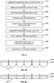
- FIGs. 3A-3D illustrate an example lamination of diced platelets 250 with wavelength conversion laminates to light emitting structures 150 on a substrate, and the molding of reflective material around each laminate structure on the substrate.
- the individual platelets 250 with laminate wavelength conversion material 220 are placed upon the light emitting structures 150, using, for example, a conventional pick-and-place machine with heating stage, common in the art of semiconductor manufacture.
- the temperature of the heating stage is around 120-150°C thus allowing the wavelength conversion material to adhere to light emitting structure 150.
- the final cure can take 1-4 hours depending on the type of polymer in lamination film.
- a material 310 may be applied to reflect the converted light, protect the light emitting element 110 and wavelength conversion material 220 from environmental effects, and/or to provide structural support to the resultant device.
- the encasing material 310 is finished to expose the light emitting surface 235 of the transparent substrate element 230.
- Microbead blasting or other planning techniques may be used to effect this surface finishing of the encasing material 310.
- the surface finishing may also roughen the surface of the substrate element 230, providing an increase in light output efficiency through that surface by reducing total internal reflections (TIR) at the surface.
- TIR total internal reflections
- the encasing material may be reflective of the light emitted by the light emitting element 110 and any light emitted by wavelength conversion film 220. This material is arranged to reflect light that would otherwise escape through the sides of the platelet 250 and structure 150 so that it may eventually escape via the light emitting surface 235 of the transparent substrate 230.
- a mixture of silicone and TiO 2 with a concentration of 20% TiO 2 or more provides for a highly reflective encasing material 310, although other materials may be used.
- the substrate 130 and the encasing material 310 may be sliced/diced, as illustrated by cutting lines 320 in FIG. 3D , to provide individual light emitting devices 350.
- the resultant light emitting devices 350 can be expected to exhibit consistent light output characteristics among devices 350 due to the use of a preformed and pre-characterized wavelength conversion film 220 that is match to the characteristics of the light emitting elements 110 on the substrate 130.
- the devices 350 can also be expected to exhibit high light output efficiency due to the absence of glue layers and due to the presence of reflective materials 310 and 140.
- the devices 350 can also be expected to exhibit good thermal dissipation due, again, to the absence of glue layers and due to the use of a transparent substrate 230 with high thermal conductivity, such as glass.
- FIG. 4 illustrates an example flow diagram for a multi-stage lamination of a wavelength conversion film to a transparent substrate and to a light emitting element, and subsequent molding of reflective material around each laminate structure.
- a transparent substrate of glass and a wavelength conversion film comprising phosphor, such as phosphor embedded in a silicone polymer.
- the phosphor film is laminated onto the glass substrate.
- the lamination may be effected by heating the glass to 70-100°C, which will leave the phosphor film in a semi-cured state.
- That sheet may be removed, at 420. Note, however, that the supporting sheet may also be removed before the heat is applied to laminate the phosphor film to the glass.
- the phosphor laminated glass is sliced/diced to provide individual phosphor-glass platelets that are sized to cover the light emitting surface area of the light emitting elements that are provided on a substrate, at 440.
- the light emitting elements that are provided on the substrate may be selected to have light emitting characteristics that are matched to the characteristics of the phosphor film to provide a desired composite color output; or, the particular phosphor film may be selected to match the characteristics of the light emitting elements to provide the desired composite color output.
- the glass-phosphor platelets are placed upon each light emitting element on the substrate, with the phosphor in direct contact with the light emitting surface of the light emitting element.
- the glass-phosphor platelets are laminated to the light emitting elements by applying heat at 120-150°C.
- the substrate with the light emitting elements may be preheated to this temperature before the glass-phosphor platelets are placed upon the light emitting elements at 450.
- a reflective mold material is applied to surround each of the laminated light emitting and wavelength converting structures on the substrate, and allowed and/or further processed to harden the mold material.
- the particular hardening process will be dependent upon the particular mold material used.
- the material is finished to expose the surface of the glass-phosphor platelet.
- the substrate with light emitting and wavelength converting structures surrounded by the mold material is sliced/diced to form individual light emitting devices.
- the substrate generally includes contacts that extend through the substrate, allowing external contact to the contact pads of the light emitting element.
- the substrate may be removed to expose the contact pads. This removal may occur prior to the slicing/dicing of the encased light emitting and wavelength converting structures, thereby allowing the substrate to be reused.
- the transparent substrate has been illustrated as a rectilinear structure with flat upper and lower surfaces.
- the transparent substrate may be shaped to provide a desired light output pattern through its light emitting surface.
- FIGs. 5A-5B illustrate example alternative shaped transparent substrates.
- the wavelength converting film 220 is laminated to a substantially flat surface of the transparent substrate 530, opposite the surfaces 510, 520 of the substrate 530 that will eventually form the light emitting surface of the finished light emitting device (not shown).
- the light emitting surface 510 of the transparent substrate 530 includes hemispherical domes that serve to allow the light that to exit the surface 510 within a broad range of angles.
- the light emitting surface 520 of the transparent substrate 530 includes shaped contours that serve to collimate the light that exits the surface 520.
- the light emitting surface of the transparent substrate 530 may be formed in any of a variety of shapes or patterns so as to provide a desired light output pattern from the device.
- the wavelength converting material is deposited in liquid/semi-liquid form upon the transparent substrate, rather than the release film, then spun or otherwise processed to form a coating of the desired thickness.
Landscapes
- Engineering & Computer Science (AREA)
- Microelectronics & Electronic Packaging (AREA)
- Manufacturing & Machinery (AREA)
- Computer Hardware Design (AREA)
- Power Engineering (AREA)
- Led Device Packages (AREA)
Applications Claiming Priority (2)
| Application Number | Priority Date | Filing Date | Title |
|---|---|---|---|
| US201461924283P | 2014-01-07 | 2014-01-07 | |
| PCT/IB2014/067412 WO2015104623A1 (en) | 2014-01-07 | 2014-12-30 | Glueless light emitting device with phosphor converter |
Publications (2)
| Publication Number | Publication Date |
|---|---|
| EP3092666A1 EP3092666A1 (en) | 2016-11-16 |
| EP3092666B1 true EP3092666B1 (en) | 2019-08-28 |
Family
ID=52472353
Family Applications (1)
| Application Number | Title | Priority Date | Filing Date |
|---|---|---|---|
| EP14837008.3A Active EP3092666B1 (en) | 2014-01-07 | 2014-12-30 | Glueless light emitting device with phosphor converter |
Country Status (7)
| Country | Link |
|---|---|
| US (1) | US11024781B2 (ko) |
| EP (1) | EP3092666B1 (ko) |
| JP (1) | JP6709159B2 (ko) |
| KR (1) | KR102323289B1 (ko) |
| CN (2) | CN105874617A (ko) |
| TW (1) | TWI724985B (ko) |
| WO (1) | WO2015104623A1 (ko) |
Families Citing this family (25)
| Publication number | Priority date | Publication date | Assignee | Title |
|---|---|---|---|---|
| JP6217705B2 (ja) * | 2015-07-28 | 2017-10-25 | 日亜化学工業株式会社 | 発光装置及びその製造方法 |
| DE102015113961A1 (de) * | 2015-08-24 | 2017-03-02 | Osram Opto Semiconductors Gmbh | Verfahren zum Herstellen eines Konverterelements, Verfahren zum Herstellen eines optoelektronischen Bauelements, Konverterelement und optoelektronisches Bauelement |
| TWI677114B (zh) * | 2015-10-05 | 2019-11-11 | 行家光電股份有限公司 | 具導角反射結構的發光裝置 |
| US10763404B2 (en) | 2015-10-05 | 2020-09-01 | Maven Optronics Co., Ltd. | Light emitting device with beveled reflector and manufacturing method of the same |
| EP3200248B1 (en) * | 2016-01-28 | 2020-09-30 | Maven Optronics Co., Ltd. | Light emitting device with asymmetrical radiation pattern and manufacturing method of the same |
| CN107039572B (zh) * | 2016-02-03 | 2019-05-10 | 行家光电股份有限公司 | 具非对称性光形的发光装置及其制造方法 |
| JP6304297B2 (ja) | 2016-04-06 | 2018-04-04 | 日亜化学工業株式会社 | 発光装置の製造方法 |
| CN109791968A (zh) | 2016-07-26 | 2019-05-21 | 克利公司 | 发光二极管、组件和相关方法 |
| TWI599078B (zh) * | 2016-08-05 | 2017-09-11 | 行家光電股份有限公司 | 具濕氣阻隔結構之晶片級封裝發光裝置 |
| JP6798279B2 (ja) * | 2016-11-28 | 2020-12-09 | 豊田合成株式会社 | 発光装置の製造方法 |
| JP2018155968A (ja) | 2017-03-17 | 2018-10-04 | 日亜化学工業株式会社 | 透光性部材の製造方法及び発光装置の製造方法 |
| JP6471764B2 (ja) * | 2017-03-31 | 2019-02-20 | 日亜化学工業株式会社 | 発光装置の製造方法 |
| KR101877237B1 (ko) * | 2017-05-23 | 2018-08-09 | 주식회사 세미콘라이트 | 반도체 발광소자 및 이의 제조 방법 |
| WO2019051780A1 (zh) * | 2017-09-15 | 2019-03-21 | 厦门市三安光电科技有限公司 | 一种白光led封装结构以及白光源系统 |
| JP6677232B2 (ja) * | 2017-09-29 | 2020-04-08 | 日亜化学工業株式会社 | 発光装置の製造方法 |
| US11335835B2 (en) * | 2017-12-20 | 2022-05-17 | Lumileds Llc | Converter fill for LED array |
| US11121298B2 (en) | 2018-05-25 | 2021-09-14 | Creeled, Inc. | Light-emitting diode packages with individually controllable light-emitting diode chips |
| DE102018119323A1 (de) * | 2018-08-08 | 2020-02-13 | Osram Opto Semiconductors Gmbh | Verfahren zum Herstellen von Konversionselementen, Konversionselemente, Verfahren zum Herstellen eines lichtemittierenden Halbleiterbauteils und lichtemittierendes Halbleiterbauteil |
| USD902448S1 (en) | 2018-08-31 | 2020-11-17 | Cree, Inc. | Light emitting diode package |
| US11233183B2 (en) * | 2018-08-31 | 2022-01-25 | Creeled, Inc. | Light-emitting diodes, light-emitting diode arrays and related devices |
| US11335833B2 (en) * | 2018-08-31 | 2022-05-17 | Creeled, Inc. | Light-emitting diodes, light-emitting diode arrays and related devices |
| DE102018127521A1 (de) * | 2018-11-05 | 2020-05-07 | Osram Opto Semiconductors Gmbh | Optoelektronisches Halbleiterbauelement und Verfahren zur Herstellung eines optoelektronischen Halbleiterbauelements |
| US10910433B2 (en) * | 2018-12-31 | 2021-02-02 | Lumileds Llc | Pixelated LED array with optical elements |
| US11101411B2 (en) * | 2019-06-26 | 2021-08-24 | Creeled, Inc. | Solid-state light emitting devices including light emitting diodes in package structures |
| DE102022122981A1 (de) * | 2022-09-09 | 2024-03-14 | Ams-Osram International Gmbh | Verfahren zum Herstellen eines optoelektronischen Bauelements und optoelektronisches Bauelement |
Citations (1)
| Publication number | Priority date | Publication date | Assignee | Title |
|---|---|---|---|---|
| JP2013001791A (ja) * | 2011-06-16 | 2013-01-07 | Toray Ind Inc | 蛍光体含有シート、それを用いたled発光装置およびその製造方法 |
Family Cites Families (34)
| Publication number | Priority date | Publication date | Assignee | Title |
|---|---|---|---|---|
| JP4109756B2 (ja) | 1998-07-07 | 2008-07-02 | スタンレー電気株式会社 | 発光ダイオード |
| US7361938B2 (en) * | 2004-06-03 | 2008-04-22 | Philips Lumileds Lighting Company Llc | Luminescent ceramic for a light emitting device |
| JP4857596B2 (ja) * | 2004-06-24 | 2012-01-18 | 豊田合成株式会社 | 発光素子の製造方法 |
| US7560294B2 (en) | 2004-06-07 | 2009-07-14 | Toyoda Gosei Co., Ltd. | Light emitting element and method of making same |
| US7553683B2 (en) * | 2004-06-09 | 2009-06-30 | Philips Lumiled Lighting Co., Llc | Method of forming pre-fabricated wavelength converting elements for semiconductor light emitting devices |
| US7256483B2 (en) | 2004-10-28 | 2007-08-14 | Philips Lumileds Lighting Company, Llc | Package-integrated thin film LED |
| US7858408B2 (en) * | 2004-11-15 | 2010-12-28 | Koninklijke Philips Electronics N.V. | LED with phosphor tile and overmolded phosphor in lens |
| US7344952B2 (en) * | 2005-10-28 | 2008-03-18 | Philips Lumileds Lighting Company, Llc | Laminating encapsulant film containing phosphor over LEDs |
| US8080828B2 (en) * | 2006-06-09 | 2011-12-20 | Philips Lumileds Lighting Company, Llc | Low profile side emitting LED with window layer and phosphor layer |
| US20080121911A1 (en) * | 2006-11-28 | 2008-05-29 | Cree, Inc. | Optical preforms for solid state light emitting dice, and methods and systems for fabricating and assembling same |
| US7858198B2 (en) * | 2007-04-10 | 2010-12-28 | Shin-Etsu Chemical Co., Ltd. | Phosphor-containing adhesive silicone composition, composition sheet formed of the composition, and method of producing light emitting device using the sheet |
| TWI404228B (zh) | 2007-07-12 | 2013-08-01 | Epistar Corp | 半導體發光裝置與其製造方法 |
| US9024340B2 (en) * | 2007-11-29 | 2015-05-05 | Nichia Corporation | Light emitting apparatus and method for producing the same |
| US10147843B2 (en) * | 2008-07-24 | 2018-12-04 | Lumileds Llc | Semiconductor light emitting device including a window layer and a light-directing structure |
| JP5518502B2 (ja) | 2009-01-27 | 2014-06-11 | シチズン電子株式会社 | 発光ダイオードの製造方法 |
| US7855394B2 (en) * | 2009-06-18 | 2010-12-21 | Bridgelux, Inc. | LED array package covered with a highly thermal conductive plate |
| US9048404B2 (en) * | 2009-07-06 | 2015-06-02 | Zhuo Sun | Thin flat solid state light source module |
| US8431423B2 (en) * | 2009-07-16 | 2013-04-30 | Koninklijke Philips Electronics N.V. | Reflective substrate for LEDS |
| US20110049545A1 (en) | 2009-09-02 | 2011-03-03 | Koninklijke Philips Electronics N.V. | Led package with phosphor plate and reflective substrate |
| JP2012033823A (ja) | 2010-08-02 | 2012-02-16 | Stanley Electric Co Ltd | 発光装置およびその製造方法 |
| WO2012026757A2 (ko) * | 2010-08-25 | 2012-03-01 | 삼성엘이디 주식회사 | 형광체 필름, 이의 제조방법, 형광층 도포 방법, 발광소자 패키지의 제조방법 및 발광소자 패키지 |
| DE102010042217A1 (de) | 2010-10-08 | 2012-04-12 | Osram Ag | Optoelektronisches Halbleiterbauelement und Verfahren zu seiner Herstellung |
| CN102185042A (zh) * | 2011-03-28 | 2011-09-14 | 北京大学深圳研究生院 | Led封装方法、封装器件、光调节方法及系统 |
| US8884330B2 (en) * | 2011-04-13 | 2014-11-11 | Osram Sylvania Inc. | LED wavelength-converting structure including a thin film structure |
| JP2013016588A (ja) * | 2011-07-01 | 2013-01-24 | Citizen Electronics Co Ltd | Led発光装置 |
| JP2013038187A (ja) | 2011-08-05 | 2013-02-21 | Stanley Electric Co Ltd | 発光装置およびその製造方法 |
| JP2013135084A (ja) * | 2011-12-26 | 2013-07-08 | Nitto Denko Corp | 発光ダイオード装置の製造方法 |
| JP6033557B2 (ja) | 2012-03-06 | 2016-11-30 | 日東電工株式会社 | 封止シート、および、それを用いた発光ダイオード装置の製造方法 |
| CN102800794A (zh) * | 2012-08-17 | 2012-11-28 | 南通脉锐光电科技有限公司 | 一种光学波长转换器件以及在白光发光器件的应用 |
| JP2014093403A (ja) * | 2012-11-02 | 2014-05-19 | Shin Etsu Chem Co Ltd | 熱硬化性シリコーン樹脂シート及びその製造方法、該熱硬化性シリコーン樹脂シートを使用する発光装置及びその製造方法 |
| JP2014096491A (ja) * | 2012-11-09 | 2014-05-22 | Nitto Denko Corp | 蛍光体層被覆半導体素子、その製造方法、半導体装置およびその製造方法 |
| JP6070498B2 (ja) * | 2012-12-21 | 2017-02-01 | 信越化学工業株式会社 | 蛍光体含有層と白色顔料含有層を有する熱硬化性シリコーン樹脂シート、それを使用する発光装置の製造方法及び封止発光半導体装置 |
| CN103165797B (zh) * | 2013-03-13 | 2016-08-03 | 上海大学 | 白光led薄膜封装用荧光粉预制薄膜封装方法 |
| CN103236485B (zh) * | 2013-04-16 | 2016-01-13 | 哈尔滨鎏霞光电技术有限公司 | 一种在蓝宝石透明导热板上制作发光体的方法 |
-
2014
- 2014-12-30 US US15/102,986 patent/US11024781B2/en active Active
- 2014-12-30 JP JP2016544575A patent/JP6709159B2/ja active Active
- 2014-12-30 EP EP14837008.3A patent/EP3092666B1/en active Active
- 2014-12-30 CN CN201480072576.7A patent/CN105874617A/zh active Pending
- 2014-12-30 WO PCT/IB2014/067412 patent/WO2015104623A1/en active Application Filing
- 2014-12-30 CN CN201910202058.7A patent/CN110010746A/zh active Pending
- 2014-12-30 KR KR1020167021557A patent/KR102323289B1/ko active IP Right Grant
-
2015
- 2015-01-07 TW TW104100427A patent/TWI724985B/zh active
Patent Citations (2)
| Publication number | Priority date | Publication date | Assignee | Title |
|---|---|---|---|---|
| JP2013001791A (ja) * | 2011-06-16 | 2013-01-07 | Toray Ind Inc | 蛍光体含有シート、それを用いたled発光装置およびその製造方法 |
| EP2610314A1 (en) * | 2011-06-16 | 2013-07-03 | Toray Industries, Inc. | Phosphor-containing sheet, led light emitting device using same, and method for manufacturing led light emitting device |
Also Published As
| Publication number | Publication date |
|---|---|
| CN105874617A (zh) | 2016-08-17 |
| WO2015104623A1 (en) | 2015-07-16 |
| TW201539801A (zh) | 2015-10-16 |
| US11024781B2 (en) | 2021-06-01 |
| EP3092666A1 (en) | 2016-11-16 |
| CN110010746A (zh) | 2019-07-12 |
| KR20160106152A (ko) | 2016-09-09 |
| KR102323289B1 (ko) | 2021-11-08 |
| JP6709159B2 (ja) | 2020-06-10 |
| JP2017501589A (ja) | 2017-01-12 |
| US20170301832A1 (en) | 2017-10-19 |
| TWI724985B (zh) | 2021-04-21 |
Similar Documents
| Publication | Publication Date | Title |
|---|---|---|
| EP3092666B1 (en) | Glueless light emitting device with phosphor converter | |
| JP5064278B2 (ja) | 光半導体素子封止用樹脂シートおよび光半導体装置 | |
| US20110031516A1 (en) | Led with silicone layer and laminated remote phosphor layer | |
| EP3511612B1 (en) | A coated optical semiconductor element | |
| KR101641384B1 (ko) | 광반도체의 캡슐화를 위한 시트 | |
| US20140220714A1 (en) | Method for manufacturing semiconductor light-emitting element | |
| JP5078644B2 (ja) | 光半導体素子封止用樹脂シートおよび光半導体装置 | |
| WO2010131090A1 (en) | Led device with light extracting rough structure and manufacturing methods thereof | |
| EP2689458B1 (en) | Patterned uv sensitive silicone-phosphor layer over leds, and method for fabricating the same | |
| JP2013501372A5 (ko) | ||
| WO2012023119A1 (en) | Lamination process for leds | |
| JP2018160678A (ja) | ラミネートフィルム、ラミネート構造及びその製造方法 | |
| TW201338213A (zh) | 發光二極體封裝結構之製造方法 | |
| WO2014203793A1 (ja) | 発光装置、その製造のための封止フィルム積層体、および発光装置の製造方法 | |
| WO2013075393A1 (en) | Led device with a light extracting rough structure and manufacturing methods thereof | |
| US20180033925A1 (en) | Method of producing a light-emitting device, and light-emitting device | |
| US20120032217A1 (en) | White led device and manufacturing method thereof | |
| EP3188261B1 (en) | Chip scale packaging light emitting device and manufacturing method of the same | |
| JP2019201089A (ja) | チップスケールパッケージング発光素子の斜角チップ反射器およびその製造方法 | |
| JP2018006490A (ja) | シート成形体の製造方法、及びそれを用いた発光装置の製造方法 | |
| WO2017052800A1 (en) | Surface emitter with light-emitting area equal to the led top surface and its fabrication | |
| US8994040B2 (en) | Method of producing an optoelectronic component and component | |
| WO2014207599A1 (en) | Transfer of optical thin films and barrier films from releasable substrates for led manufacture | |
| JP2019064136A (ja) | 透光性シートの製造方法 | |
| JP2014127525A (ja) | 封止用樹脂付き金型成型用離型フィルム、それを用いた光半導体素子の封止方法及び該封止された光半導体素子を備えた光半導体デバイス |
Legal Events
| Date | Code | Title | Description |
|---|---|---|---|
| PUAI | Public reference made under article 153(3) epc to a published international application that has entered the european phase |
Free format text: ORIGINAL CODE: 0009012 |
|
| 17P | Request for examination filed |
Effective date: 20160808 |
|
| AK | Designated contracting states |
Kind code of ref document: A1 Designated state(s): AL AT BE BG CH CY CZ DE DK EE ES FI FR GB GR HR HU IE IS IT LI LT LU LV MC MK MT NL NO PL PT RO RS SE SI SK SM TR |
|
| AX | Request for extension of the european patent |
Extension state: BA ME |
|
| STAA | Information on the status of an ep patent application or granted ep patent |
Free format text: STATUS: EXAMINATION IS IN PROGRESS |
|
| 17Q | First examination report despatched |
Effective date: 20170119 |
|
| DAX | Request for extension of the european patent (deleted) | ||
| RAP1 | Party data changed (applicant data changed or rights of an application transferred) |
Owner name: LUMILEDS HOLDING B.V. |
|
| RAP1 | Party data changed (applicant data changed or rights of an application transferred) |
Owner name: LUMILEDS HOLDING B.V. |
|
| GRAP | Despatch of communication of intention to grant a patent |
Free format text: ORIGINAL CODE: EPIDOSNIGR1 |
|
| STAA | Information on the status of an ep patent application or granted ep patent |
Free format text: STATUS: GRANT OF PATENT IS INTENDED |
|
| RIC1 | Information provided on ipc code assigned before grant |
Ipc: H01L 33/60 20100101ALI20190319BHEP Ipc: H01L 33/58 20100101ALN20190319BHEP Ipc: H01L 33/00 20100101ALN20190319BHEP Ipc: H01L 33/50 20100101AFI20190319BHEP |
|
| INTG | Intention to grant announced |
Effective date: 20190408 |
|
| GRAS | Grant fee paid |
Free format text: ORIGINAL CODE: EPIDOSNIGR3 |
|
| GRAA | (expected) grant |
Free format text: ORIGINAL CODE: 0009210 |
|
| STAA | Information on the status of an ep patent application or granted ep patent |
Free format text: STATUS: THE PATENT HAS BEEN GRANTED |
|
| AK | Designated contracting states |
Kind code of ref document: B1 Designated state(s): AL AT BE BG CH CY CZ DE DK EE ES FI FR GB GR HR HU IE IS IT LI LT LU LV MC MK MT NL NO PL PT RO RS SE SI SK SM TR |
|
| REG | Reference to a national code |
Ref country code: GB Ref legal event code: FG4D |
|
| REG | Reference to a national code |
Ref country code: CH Ref legal event code: EP |
|
| REG | Reference to a national code |
Ref country code: AT Ref legal event code: REF Ref document number: 1173486 Country of ref document: AT Kind code of ref document: T Effective date: 20190915 |
|
| REG | Reference to a national code |
Ref country code: IE Ref legal event code: FG4D |
|
| REG | Reference to a national code |
Ref country code: DE Ref legal event code: R096 Ref document number: 602014052697 Country of ref document: DE |
|
| REG | Reference to a national code |
Ref country code: NL Ref legal event code: MP Effective date: 20190828 |
|
| REG | Reference to a national code |
Ref country code: LT Ref legal event code: MG4D |
|
| PG25 | Lapsed in a contracting state [announced via postgrant information from national office to epo] |
Ref country code: NL Free format text: LAPSE BECAUSE OF FAILURE TO SUBMIT A TRANSLATION OF THE DESCRIPTION OR TO PAY THE FEE WITHIN THE PRESCRIBED TIME-LIMIT Effective date: 20190828 Ref country code: HR Free format text: LAPSE BECAUSE OF FAILURE TO SUBMIT A TRANSLATION OF THE DESCRIPTION OR TO PAY THE FEE WITHIN THE PRESCRIBED TIME-LIMIT Effective date: 20190828 Ref country code: BG Free format text: LAPSE BECAUSE OF FAILURE TO SUBMIT A TRANSLATION OF THE DESCRIPTION OR TO PAY THE FEE WITHIN THE PRESCRIBED TIME-LIMIT Effective date: 20191128 Ref country code: SE Free format text: LAPSE BECAUSE OF FAILURE TO SUBMIT A TRANSLATION OF THE DESCRIPTION OR TO PAY THE FEE WITHIN THE PRESCRIBED TIME-LIMIT Effective date: 20190828 Ref country code: LT Free format text: LAPSE BECAUSE OF FAILURE TO SUBMIT A TRANSLATION OF THE DESCRIPTION OR TO PAY THE FEE WITHIN THE PRESCRIBED TIME-LIMIT Effective date: 20190828 Ref country code: FI Free format text: LAPSE BECAUSE OF FAILURE TO SUBMIT A TRANSLATION OF THE DESCRIPTION OR TO PAY THE FEE WITHIN THE PRESCRIBED TIME-LIMIT Effective date: 20190828 Ref country code: NO Free format text: LAPSE BECAUSE OF FAILURE TO SUBMIT A TRANSLATION OF THE DESCRIPTION OR TO PAY THE FEE WITHIN THE PRESCRIBED TIME-LIMIT Effective date: 20191128 Ref country code: PT Free format text: LAPSE BECAUSE OF FAILURE TO SUBMIT A TRANSLATION OF THE DESCRIPTION OR TO PAY THE FEE WITHIN THE PRESCRIBED TIME-LIMIT Effective date: 20191230 |
|
| PG25 | Lapsed in a contracting state [announced via postgrant information from national office to epo] |
Ref country code: LV Free format text: LAPSE BECAUSE OF FAILURE TO SUBMIT A TRANSLATION OF THE DESCRIPTION OR TO PAY THE FEE WITHIN THE PRESCRIBED TIME-LIMIT Effective date: 20190828 Ref country code: RS Free format text: LAPSE BECAUSE OF FAILURE TO SUBMIT A TRANSLATION OF THE DESCRIPTION OR TO PAY THE FEE WITHIN THE PRESCRIBED TIME-LIMIT Effective date: 20190828 Ref country code: GR Free format text: LAPSE BECAUSE OF FAILURE TO SUBMIT A TRANSLATION OF THE DESCRIPTION OR TO PAY THE FEE WITHIN THE PRESCRIBED TIME-LIMIT Effective date: 20191129 Ref country code: IS Free format text: LAPSE BECAUSE OF FAILURE TO SUBMIT A TRANSLATION OF THE DESCRIPTION OR TO PAY THE FEE WITHIN THE PRESCRIBED TIME-LIMIT Effective date: 20191228 Ref country code: ES Free format text: LAPSE BECAUSE OF FAILURE TO SUBMIT A TRANSLATION OF THE DESCRIPTION OR TO PAY THE FEE WITHIN THE PRESCRIBED TIME-LIMIT Effective date: 20190828 Ref country code: AL Free format text: LAPSE BECAUSE OF FAILURE TO SUBMIT A TRANSLATION OF THE DESCRIPTION OR TO PAY THE FEE WITHIN THE PRESCRIBED TIME-LIMIT Effective date: 20190828 |
|
| REG | Reference to a national code |
Ref country code: AT Ref legal event code: MK05 Ref document number: 1173486 Country of ref document: AT Kind code of ref document: T Effective date: 20190828 |
|
| PG25 | Lapsed in a contracting state [announced via postgrant information from national office to epo] |
Ref country code: TR Free format text: LAPSE BECAUSE OF FAILURE TO SUBMIT A TRANSLATION OF THE DESCRIPTION OR TO PAY THE FEE WITHIN THE PRESCRIBED TIME-LIMIT Effective date: 20190828 |
|
| PG25 | Lapsed in a contracting state [announced via postgrant information from national office to epo] |
Ref country code: DK Free format text: LAPSE BECAUSE OF FAILURE TO SUBMIT A TRANSLATION OF THE DESCRIPTION OR TO PAY THE FEE WITHIN THE PRESCRIBED TIME-LIMIT Effective date: 20190828 Ref country code: EE Free format text: LAPSE BECAUSE OF FAILURE TO SUBMIT A TRANSLATION OF THE DESCRIPTION OR TO PAY THE FEE WITHIN THE PRESCRIBED TIME-LIMIT Effective date: 20190828 Ref country code: AT Free format text: LAPSE BECAUSE OF FAILURE TO SUBMIT A TRANSLATION OF THE DESCRIPTION OR TO PAY THE FEE WITHIN THE PRESCRIBED TIME-LIMIT Effective date: 20190828 Ref country code: IT Free format text: LAPSE BECAUSE OF FAILURE TO SUBMIT A TRANSLATION OF THE DESCRIPTION OR TO PAY THE FEE WITHIN THE PRESCRIBED TIME-LIMIT Effective date: 20190828 Ref country code: RO Free format text: LAPSE BECAUSE OF FAILURE TO SUBMIT A TRANSLATION OF THE DESCRIPTION OR TO PAY THE FEE WITHIN THE PRESCRIBED TIME-LIMIT Effective date: 20190828 Ref country code: PL Free format text: LAPSE BECAUSE OF FAILURE TO SUBMIT A TRANSLATION OF THE DESCRIPTION OR TO PAY THE FEE WITHIN THE PRESCRIBED TIME-LIMIT Effective date: 20190828 |
|
| PG25 | Lapsed in a contracting state [announced via postgrant information from national office to epo] |
Ref country code: IS Free format text: LAPSE BECAUSE OF FAILURE TO SUBMIT A TRANSLATION OF THE DESCRIPTION OR TO PAY THE FEE WITHIN THE PRESCRIBED TIME-LIMIT Effective date: 20200224 Ref country code: SM Free format text: LAPSE BECAUSE OF FAILURE TO SUBMIT A TRANSLATION OF THE DESCRIPTION OR TO PAY THE FEE WITHIN THE PRESCRIBED TIME-LIMIT Effective date: 20190828 Ref country code: SK Free format text: LAPSE BECAUSE OF FAILURE TO SUBMIT A TRANSLATION OF THE DESCRIPTION OR TO PAY THE FEE WITHIN THE PRESCRIBED TIME-LIMIT Effective date: 20190828 Ref country code: CZ Free format text: LAPSE BECAUSE OF FAILURE TO SUBMIT A TRANSLATION OF THE DESCRIPTION OR TO PAY THE FEE WITHIN THE PRESCRIBED TIME-LIMIT Effective date: 20190828 |
|
| REG | Reference to a national code |
Ref country code: DE Ref legal event code: R097 Ref document number: 602014052697 Country of ref document: DE |
|
| PLBE | No opposition filed within time limit |
Free format text: ORIGINAL CODE: 0009261 |
|
| STAA | Information on the status of an ep patent application or granted ep patent |
Free format text: STATUS: NO OPPOSITION FILED WITHIN TIME LIMIT |
|
| PG2D | Information on lapse in contracting state deleted |
Ref country code: IS |
|
| REG | Reference to a national code |
Ref country code: CH Ref legal event code: PL |
|
| 26N | No opposition filed |
Effective date: 20200603 |
|
| REG | Reference to a national code |
Ref country code: BE Ref legal event code: MM Effective date: 20191231 |
|
| PG25 | Lapsed in a contracting state [announced via postgrant information from national office to epo] |
Ref country code: SI Free format text: LAPSE BECAUSE OF FAILURE TO SUBMIT A TRANSLATION OF THE DESCRIPTION OR TO PAY THE FEE WITHIN THE PRESCRIBED TIME-LIMIT Effective date: 20190828 Ref country code: MC Free format text: LAPSE BECAUSE OF FAILURE TO SUBMIT A TRANSLATION OF THE DESCRIPTION OR TO PAY THE FEE WITHIN THE PRESCRIBED TIME-LIMIT Effective date: 20190828 |
|
| PG25 | Lapsed in a contracting state [announced via postgrant information from national office to epo] |
Ref country code: IE Free format text: LAPSE BECAUSE OF NON-PAYMENT OF DUE FEES Effective date: 20191230 Ref country code: LU Free format text: LAPSE BECAUSE OF NON-PAYMENT OF DUE FEES Effective date: 20191230 |
|
| PG25 | Lapsed in a contracting state [announced via postgrant information from national office to epo] |
Ref country code: LI Free format text: LAPSE BECAUSE OF NON-PAYMENT OF DUE FEES Effective date: 20191231 Ref country code: CH Free format text: LAPSE BECAUSE OF NON-PAYMENT OF DUE FEES Effective date: 20191231 Ref country code: BE Free format text: LAPSE BECAUSE OF NON-PAYMENT OF DUE FEES Effective date: 20191231 |
|
| PG25 | Lapsed in a contracting state [announced via postgrant information from national office to epo] |
Ref country code: CY Free format text: LAPSE BECAUSE OF FAILURE TO SUBMIT A TRANSLATION OF THE DESCRIPTION OR TO PAY THE FEE WITHIN THE PRESCRIBED TIME-LIMIT Effective date: 20190828 |
|
| PG25 | Lapsed in a contracting state [announced via postgrant information from national office to epo] |
Ref country code: HU Free format text: LAPSE BECAUSE OF FAILURE TO SUBMIT A TRANSLATION OF THE DESCRIPTION OR TO PAY THE FEE WITHIN THE PRESCRIBED TIME-LIMIT; INVALID AB INITIO Effective date: 20141230 Ref country code: MT Free format text: LAPSE BECAUSE OF FAILURE TO SUBMIT A TRANSLATION OF THE DESCRIPTION OR TO PAY THE FEE WITHIN THE PRESCRIBED TIME-LIMIT Effective date: 20190828 |
|
| PG25 | Lapsed in a contracting state [announced via postgrant information from national office to epo] |
Ref country code: MK Free format text: LAPSE BECAUSE OF FAILURE TO SUBMIT A TRANSLATION OF THE DESCRIPTION OR TO PAY THE FEE WITHIN THE PRESCRIBED TIME-LIMIT Effective date: 20190828 |
|
| P01 | Opt-out of the competence of the unified patent court (upc) registered |
Effective date: 20230530 |
|
| PGFP | Annual fee paid to national office [announced via postgrant information from national office to epo] |
Ref country code: GB Payment date: 20231219 Year of fee payment: 10 |
|
| PGFP | Annual fee paid to national office [announced via postgrant information from national office to epo] |
Ref country code: FR Payment date: 20231226 Year of fee payment: 10 |
|
| PGFP | Annual fee paid to national office [announced via postgrant information from national office to epo] |
Ref country code: DE Payment date: 20231227 Year of fee payment: 10 |