EP3090923B1 - Structure de seuil de porte latéral pour véhicule automobile - Google Patents
Structure de seuil de porte latéral pour véhicule automobile Download PDFInfo
- Publication number
- EP3090923B1 EP3090923B1 EP15166893.6A EP15166893A EP3090923B1 EP 3090923 B1 EP3090923 B1 EP 3090923B1 EP 15166893 A EP15166893 A EP 15166893A EP 3090923 B1 EP3090923 B1 EP 3090923B1
- Authority
- EP
- European Patent Office
- Prior art keywords
- connection
- sill structure
- reinforcement
- outer member
- vehicle
- Prior art date
- Legal status (The legal status is an assumption and is not a legal conclusion. Google has not performed a legal analysis and makes no representation as to the accuracy of the status listed.)
- Active
Links
- 230000002787 reinforcement Effects 0.000 claims description 77
- 239000000463 material Substances 0.000 claims description 20
- 238000007373 indentation Methods 0.000 claims description 8
- 239000004411 aluminium Substances 0.000 claims description 6
- 229910052782 aluminium Inorganic materials 0.000 claims description 6
- XAGFODPZIPBFFR-UHFFFAOYSA-N aluminium Chemical compound [Al] XAGFODPZIPBFFR-UHFFFAOYSA-N 0.000 claims description 6
- 230000009286 beneficial effect Effects 0.000 description 6
- 238000003466 welding Methods 0.000 description 6
- 230000003014 reinforcing effect Effects 0.000 description 4
- 229910000831 Steel Inorganic materials 0.000 description 3
- 239000010959 steel Substances 0.000 description 3
- 238000005336 cracking Methods 0.000 description 2
- 238000009863 impact test Methods 0.000 description 2
- 229920002430 Fibre-reinforced plastic Polymers 0.000 description 1
- 239000000853 adhesive Substances 0.000 description 1
- 230000001070 adhesive effect Effects 0.000 description 1
- 230000000295 complement effect Effects 0.000 description 1
- 230000001419 dependent effect Effects 0.000 description 1
- 230000002349 favourable effect Effects 0.000 description 1
- 239000011151 fibre-reinforced plastic Substances 0.000 description 1
- 238000004519 manufacturing process Methods 0.000 description 1
- 229910052751 metal Inorganic materials 0.000 description 1
- 239000002184 metal Substances 0.000 description 1
- 238000000034 method Methods 0.000 description 1
- 238000012986 modification Methods 0.000 description 1
- 230000004048 modification Effects 0.000 description 1
- 239000004033 plastic Substances 0.000 description 1
- 229920003023 plastic Polymers 0.000 description 1
- 238000011076 safety test Methods 0.000 description 1
- 238000003860 storage Methods 0.000 description 1
- 239000013585 weight reducing agent Substances 0.000 description 1
Images


Classifications
-
- B—PERFORMING OPERATIONS; TRANSPORTING
- B62—LAND VEHICLES FOR TRAVELLING OTHERWISE THAN ON RAILS
- B62D—MOTOR VEHICLES; TRAILERS
- B62D25/00—Superstructure or monocoque structure sub-units; Parts or details thereof not otherwise provided for
- B62D25/20—Floors or bottom sub-units
- B62D25/2009—Floors or bottom sub-units in connection with other superstructure subunits
- B62D25/2036—Floors or bottom sub-units in connection with other superstructure subunits the subunits being side panels, sills or pillars
-
- B—PERFORMING OPERATIONS; TRANSPORTING
- B62—LAND VEHICLES FOR TRAVELLING OTHERWISE THAN ON RAILS
- B62D—MOTOR VEHICLES; TRAILERS
- B62D21/00—Understructures, i.e. chassis frame on which a vehicle body may be mounted
- B62D21/15—Understructures, i.e. chassis frame on which a vehicle body may be mounted having impact absorbing means, e.g. a frame designed to permanently or temporarily change shape or dimension upon impact with another body
- B62D21/157—Understructures, i.e. chassis frame on which a vehicle body may be mounted having impact absorbing means, e.g. a frame designed to permanently or temporarily change shape or dimension upon impact with another body for side impacts
-
- B—PERFORMING OPERATIONS; TRANSPORTING
- B62—LAND VEHICLES FOR TRAVELLING OTHERWISE THAN ON RAILS
- B62D—MOTOR VEHICLES; TRAILERS
- B62D25/00—Superstructure or monocoque structure sub-units; Parts or details thereof not otherwise provided for
- B62D25/02—Side panels
- B62D25/025—Side sills thereof
-
- B—PERFORMING OPERATIONS; TRANSPORTING
- B62—LAND VEHICLES FOR TRAVELLING OTHERWISE THAN ON RAILS
- B62D—MOTOR VEHICLES; TRAILERS
- B62D29/00—Superstructures, understructures, or sub-units thereof, characterised by the material thereof
- B62D29/008—Superstructures, understructures, or sub-units thereof, characterised by the material thereof predominantly of light alloys, e.g. extruded
Definitions
- the present disclosure relates to a sill structure for a vehicle.
- the disclosure further relates to a vehicle comprising such a sill structure.
- US patent 5,443,297 discloses a structure of a side portion of a vehicle body having a side outer panel in which a side sill outer member and a pillar outer member are integrally formed.
- a first enclosed cross-sectional member is formed by a connecting of a side sill inner member and a side sill reinforcing member.
- a second enclosed cross-sectional member is formed by connecting the side sill outer member and the side sill reinforcing member.
- Document DE 10 2013 004 852 A1 relates to a rocker panel for a vehicle body having an elongated reinforcing component configured as a hollow profile made of metal, preferably of steel, and/or of plastic, preferably of fibre-reinforced plastic.
- the reinforcing component is constructed of a group of at least two, preferably three single profiles.
- the object of the present disclosure is to overcome or ameliorate at least one of the disadvantages of the prior art, or to provide a useful alternative.
- a sill structure for a vehicle.
- the the structure comprises an outer member, an inner member, which is located laterally inside the outer member as seen in a transverse direction of the vehicle, and a reinforcement member, which is located laterally between the outer member and the inner member as seen in the transverse direction of the vehicle.
- An upper end portion of the inner member is attached to the reinforcement member in a first connection.
- An upper end portion of the outer member is attached to the reinforcement member in a second connection, which is located vertically below and separate from the first connection.
- a lower end portion of the inner member is attached to the reinforcement member and to a lower end portion of the outer member in a third connection, which is located vertically below and separate from the first connection and the second connection.
- the reinforcement member extends in a straight way or substantially straight way between the second connection and the third connection.
- the sill structure forms part of a body of the vehicle.
- the sill structure extends in a longitudinal direction of the vehicle below a front door opening and a rear door opening.
- the longitudinal direction coincides with the normal driving direction of the vehicle.
- the transverse direction is perpendicular to the longitudinal direction.
- a vertical direction is perpendicular to both the transverse direction and the longitudinal direction.
- the sill structure may be manufactured and sold as a separate unit.
- the directions as used herein are related to when the sill structure is mounted in the vehicle. However, e.g. during manufacturing, storage and transport of the sill structure, it may assume another orientation.
- the first connection is vertically above the second connection, i.e. at a higher vertical level.
- the second connection is in turn located vertically above the third connection.
- the first, second and third connections are separate from each other.
- the outer member, the inner member and the reinforcement member extend in the longitudinal direction of the vehicle for a portion, for a main portion or for the full length of the sill structure.
- the first, second and third connections also extend in the longitudinal direction of the vehicle for a portion, for a main portion or for the full length of the sill structure.
- the reinforcement member extends in a straight way or substantially straight way between the second connection and the third connection.
- the reinforcement member preferably also extends in a straight way or substantially straight way between the first and the second connection. More preferably, the reinforcement member extends in a straight way or substantially straight way between the first connection and the third connection. Extending in a straight way or substantially straight way is interpreted as that the reinforcement member extends without any bend or curvature changing the extension direction of the reinforcement member by more than 20 degrees. Preferably there is no bend or curvature hanging the extension direction of the reinforcement member by more than 10 degrees.
- the reinforcement member may for example extend the shortest distance or substantially the shortest distance between the second connection and the third connection. This is most easily seen when viewing a transverse cross-sectional profile of the sill structure.
- the first, second and/or third connections may be spot-welded or laser welded.
- an adhesive may be used or any known fastening means, such as rivets.
- the first connection may form a wind-cord flange.
- the third connection may form a sill bottom flange.
- An advantage of using a separate second connection for the outer member is that most of the side impact load will be taken up by the second connection, thereby subjecting the first connection to less load than would be the case if the outer member and the inner member were attached in the same connection.
- the second connection comprising the outer member is located vertically below the first connection.
- an upper edge of the outer member may be located vertically below the first connection and separate from the first connection, such that the outer member is not present in the first connection. This is most easily seen when viewing a transverse cross-sectional profile of the sill structure.
- the reinforcement member may extend between the first connection and the third connection at a small angle ⁇ to the vertical direction.
- the angle ⁇ may be within +/- 15 degrees, preferably within +/- 10 degrees, more preferably within +/- 5 degrees from the vertical direction. This angle ⁇ is a result of that the second connection is located laterally outwards or laterally inwards of the third connection.
- the reinforcement member may extend substantially vertically or vertically, between the first connection and third connection, i.e. along the vertical direction, in case the second connection is located vertically above of the third connection without any lateral difference.
- a transverse cross-sectional profile of the inner member may comprise a side wall portion extending substantially vertically and spaced apart from the reinforcement member, e.g. within +/- 15 degrees, preferably within +/- 10 degrees, more preferably within +/- 5 degrees from the vertical direction.
- the inner member bulges inwardly, i.e. in a direction into a passenger compartment of the vehicle, from the reinforcement member and the first and third connections.
- a portion of the inner member and a portion of the reinforcement member may form an inner chamber located vertically between the first connection and third connection.
- a transverse cross-sectional profile of the outer member may comprise a side wall portion extending substantially vertically and spaced apart from the reinforcement member, e.g. within +/- 15 degrees, preferably within +/- 10 degrees, more preferably +/- 5 degrees from the vertical direction.
- the outer member bulges outwardly, i.e. in a direction facing away from the passenger compartment, from the reinforcement member and the second and third connections.
- a portion of the outer member and a portion of the reinforcement member may form an outer chamber located vertically between the second connection and third connection.
- the transverse cross-sectional profile of the outer member may comprise an indentation, which preferably forms a step in the transverse cross-sectional profile.
- the indentation improves the strength properties of the outer member.
- the indentation allows other components to be contained in a space formed between the outer member and an outer panel, which outer panel is further described below.
- the outer member may comprise or consist of a stronger material than the inner member.
- the outer member may have a tensile strength of at least 1300 MPa.
- the inner member and/or the reinforcement member may comprise or consist of a more ductile material than the outer member.
- the elongation at fracture for the inner member and/or the reinforcement member may be selected to be above 10%.
- the materials of the outer member and the inner member may be purposely selected, such that the material of the outer member is selected to be stronger than that of the inner member, while the material of the inner member is selected to be more ductile than that of the outer member.
- the reinforcement member may comprise a material, which is more ductile than that of the outer member.
- Different kinds of material may be utilized for the outer member and the inner member, e.g. two different kinds of steel. Since two different materials may be utilized, the material properties of the respective outer member and the inner member may be selected independently of each other.
- the pole might press the sill structure laterally inwards, into the vehicle passenger compartment.
- An outside portion of the sill structure will then be subjected to a pressure load, while an inside portion of the sill structure will be subjected to a tension load.
- the outer member is stronger and the inner member is more ductile.
- the sill structure will bend without cracking, or at least it will be substantially less likely to crack, due to the high ductility of the inner member.
- the sill structure will therefore improve the ability of the vehicle to survive the side impact without suffering passenger compartment intrusion.
- the sill structure may further comprise an outer panel member located laterally outside of the outer member as seen in the transverse direction of the vehicle, which outer panel member is attached to the reinforcement member at the first connection.
- a reinforcement body may be located in the inner chamber formed by the inner member and the reinforcement member.
- the reinforcement body extends in the longitudinal direction of the vehicle for a portion of the length of the sill structure, for a main portion or for the full length of the sill structure.
- the reinforcement body may be an extruded profile, preferably an extruded aluminium profile.
- Aluminium is a suitable material, since it is good at absorbing energy, which is beneficial in a collision scenario, yet is has a relatively low weight.
- the reinforcement body may extend vertically at least up to a lower end of the second connection. Thereby a transverse load path may be formed by a substantially transversely extending portion of the outer member and the reinforcement body.
- the reinforcement body may comprise at least one wall substantially extending in the transverse direction.
- the reinforcement body may comprise outer walls, e.g. one or two, extending in the transverse direction and/or at least one inner wall extending in the transverse direction.
- a vehicle comprising a sill structure as described herein.
- Figure 1 illustrates a side view of a vehicle 10 according to the invention.
- the vehicle 10 comprises a sill structure 12 according to the invention forming part of a body of the vehicle 10. Although only one lateral side can be seen in Figure 1 , there is usually a sill structure 12 at both lateral sides of the vehicle 10.
- the sill structure 12 extends in a longitudinal direction L of the vehicle 10 below a front door opening 14 and a rear door opening 16.
- the longitudinal direction L coincides with the normal driving direction of the vehicle 10.
- the transverse direction T is perpendicular to the longitudinal direction L.
- a vertical direction V is perpendicular to both the transverse direction T and the longitudinal direction L
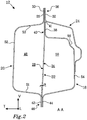
- FIG 2 illustrates a transverse cross-section of the sill structure 12 of Figure 1 .
- the sill structure 12 comprises an outer member 18, an inner member 20 and a reinforcement member 22.
- the outer member 18, the inner member 20 and the reinforcement member 22 extend in the longitudinal direction L of the vehicle 10 for a portion, for a main portion or for the full length of the sill structure 12.
- the inner member 20 is located laterally inside the outer member 18 as seen in the transverse direction T of the vehicle 10.
- the reinforcement member 22 is located laterally between the outer member 18 and the inner member 20 as seen in the transverse direction T.
- the sill structure 12 further comprises an outer panel member 24 located laterally outside of the outer member 18, which outer panel member 24 also extends in the longitudinal direction L of the vehicle 10.
- An upper end portion of the inner member 20 forming an upper flange 26 is attached to an inwards facing surface 28 of the reinforcement member 22 in a first connection 30, e.g. by spot welding or laser welding.
- An upper end portion of the outer panel member 24 forming an upper flange 32 is attached to an outwards facing surface 34 of the reinforcement member 22, e.g. by spot welding or laser welding.
- the upper flange 26 of the inner member 20 and the upper flange 32 of the outer panel member 24 form a wind-cord flange 36 together with the portion of the reinforcement member 22 to which they are attached.
- An upper end portion of the outer member 18 forming an upper flange 38 is attached to the outwards facing surface 34 of the reinforcement member 22 in a second connection 40, e.g. by spot welding or laser welding.
- the second connection 40 is located vertically below and separate from the first connection 30.
- an upper edge 41 of the outer member 18 is located vertically below and separate from the first connection 30, such that the outer member 18 is not present in the wind-cord flange 36.
- a lower end portion of the inner member 20 forming a lower flange 42 is attached to the reinforcement member 22 and to a lower end portion of the outer member 18 forming a lower flange 44 in a third connection 46, being located vertically below and separate from the first connection 30 and the second connection 40.
- the third connection 46 forms a sill bottom flange of the sill structure 12.
- a portion of the inner member 20 and a portion of the reinforcement member 22 form an inner chamber 48 located vertically between the first connection 30 and third connection 46.
- a portion of the outer member 18 and a portion of the reinforcement member 22 form an outer chamber 50 located vertically between the second connection 40 and third connection 46.
- the reinforcement member 22 extends in a straight way, or substantially straight way, between the first connection 30 and the third connection 46, in the illustrated embodiment at a small angle ⁇ to the vertical direction V.
- the angle ⁇ is within +/- 15 degrees, preferably within +/- 10 degrees, more preferably +/- 5 degrees from the vertical direction.
- This angle ⁇ is in the illustrated embodiment a result of that the second connection 38 is located laterally outwards of the third connection 46.
- the second connection 38 is located laterally inwards of the third connection 46.
- the reinforcement member 22 may also extend substantially vertically or vertically, in case the second connection 38 is located vertically above of the third connection 46 without any lateral difference.
- the reinforcement member 22 extends in a straight way or substantially straight way without any curvature or bends. In particular, there is no sharp bend changing the extension direction of the reinforcement member 22 by more than 20 degrees.
- the inner panel member 20 comprises a side wall portion 52 extending substantially vertically and spaced apart from the reinforcement member 22.
- the inner chamber 48 has a substantially trapezoidal transverse cross-sectional shape with the side wall portion 52 being the shorter of the two substantially parallel sides. If the other wall portions are close to transverse, as in the illustrated embodiment, the inner chamber 48 may even have a substantially rectangular transverse cross-sectional shape.
- the outer member 18 comprises a side wall portion 54 extending substantially vertically and spaced apart from the reinforcement member 22.
- the side wall portion 54 of the outer member 18 comprises an indentation 56 providing a step in the cross-sectional profile of the outer member 18 being beneficial for the strength properties of the outer member 18.
- the indentation 56 allows other components to be contained in a space formed between the outer member 18 and the outer panel 24.
- the outer chamber 50 has a substantially trapezoidal shape with the side wall portion 54 being the shorter of the two substantially parallel sides. Since the second connection 40 is located vertically below the first connection 30, the cross-sectional area of the outer chamber 50 is usually smaller than that of the inner chamber 48.
- the materials of the outer member 18 and the inner member 20 may be purposely selected, such that the material of the outer member 18 is selected to be stronger than that of the inner member 20, while the material of the inner member 20 is selected to be more ductile than that of the outer member 18.
- the reinforcement member 22 may comprise a material, which is more ductile than that of the outer member 18.
- Different kinds of material may be utilized for the outer member 18 and the inner member 20, e.g. two different kinds of steel. Since two different materials may be utilized, the material properties of the respective outer member 18 and the inner member 20 may be selected independently of each other.
- the pole might press the sill structure 12 laterally inwards, into the vehicle passenger compartment.
- An outside portion of the sill structure 12 will then be subjected to a pressure load, while an inside portion of the sill structure 12 will be subjected to a tension load.
- the outer member 18 is stronger and the inner member 20 is more ductile, as described above.
- the sill structure 12 as described herein will bend without cracking, or at least it will be substantially less likely to crack, due to the high ductility of the inner member 20.
- the sill structure 12 will therefore improve the ability of the vehicle 10 to survive the side impact without suffering passenger compartment intrusion.
- a reinforcement body 58 may be located in the inner chamber 48, as is illustrated in Figure 3 .
- the reinforcement body 58 extends in the longitudinal direction L of the vehicle 10 for a portion of the length of the sill structure 12, for a main portion or for the full length of the sill structure 12.
- the reinforcement body 58 is an extruded aluminium profile. Aluminium is a suitable material, since it is good at absorbing energy, which is beneficial in a collision scenario, yet is has a relatively low weight.
- the reinforcement body 58 comprises at least one wall extending substantially in the transverse direction T. In the illustrated embodiment, there are two outer walls 60, 62 extending transversely and two inner walls 64, 66 also extending transversely. The reinforcement body 58 extends vertically at least up to a lower end 67 of the second connection 40. In the illustrated embodiment it extends somewhat vertically above.
- a portion 68 of the outer member 18 being located adjacent to the second connection 40 extends substantially transversely with an angle ⁇ to a horizontal line, the angle ⁇ preferably being between 0 and 15 degrees.
- This portion 68 is substantially aligned with the upper outer wall 60 of the reinforcement body 58. If the vehicle 10 is subjected to a side impact scenario, this portion 68 may form a load path together with the transversely extending walls 60, 62, 64, 66 of the reinforcement body 58, in this embodiment in particular the upper outer wall 60, which load path is suitable for taking up forces being at least partly in the transverse direction T.
- the outer member 18 is attached to the reinforcement member 22 in its own separate connection, i.e. the second connection 40, it is possible to use a small angle ⁇ , hence providing a substantially transverse load path.
- a small angle ⁇ is beneficial also for other sill structures 12 according to the invention, also including sill structures not comprising the optional reinforcement body 58, such as the sill structure 12 illustrated in Figure 2 .
- the portion 68 will provide a load path for taking up forces being at least partly in the transverse direction T.
- a reinforcement body e.g. an extruded aluminium profile, may be provided in the outer chamber 50.
- An advantage of using a separate second connection 40 for the outer member 18 is that most of the side impact load will be taken up by the second connection 40, thereby subjecting the first connection 30 to less load, as would be the case if the outer member 18 and the inner member 20 were attached in the same connection. The first connection 30 may then be more ductile and the second connection 40 stronger.
Landscapes
- Engineering & Computer Science (AREA)
- Chemical & Material Sciences (AREA)
- Combustion & Propulsion (AREA)
- Transportation (AREA)
- Mechanical Engineering (AREA)
- Architecture (AREA)
- Structural Engineering (AREA)
- Body Structure For Vehicles (AREA)
Claims (14)
- Structure de seuil (12) pour un véhicule (10), ladite structure de seuil (12) comprenant:- un élément extérieur (18),- un élément intérieur (20) qui est situé latéralement à l'intérieur dudit élément extérieur (18), comme on peut le voir dans une direction transversale (T) dudit véhicule (10),- un élément de renforcement (22) qui est situé latéralement entre ledit élément extérieur (18) et ledit élément intérieur (20), comme on peut le voir dans ladite direction transversale (T) dudit véhicule (10),dans laquelle une partie d'extrémité supérieure (26) dudit élément intérieur (20) est attachée audit élément de renforcement (22) dans une première connexion (30),
une partie d'extrémité supérieure (32) dudit élément extérieur (18) est attachée audit élément de renforcement (22) dans une deuxième connexion (40),
une partie d'extrémité inférieure (42) dudit élément intérieur (20) est attachée audit élément de renforcement (22) et à une partie d'extrémité inférieure (44) dudit élément extérieur (18) dans une troisième connexion (46) qui est située verticalement en dessous et séparée de ladite première connexion (30) et de ladite deuxième connexion (40),
ledit élément de renforcement (22) s'étend en une ligne droite ou une ligne sensiblement droite entre ladite deuxième connexion (40) et ladite troisième connexion (46);
caractérisée en ce que ladite seconde connexion (40) est située verticalement en dessous et séparée de ladite première connexion (30). - Structure de seuil (12) selon la revendication 1, dans laquelle un bord supérieur (41) dudit élément extérieur (18) est situé verticalement en dessous de ladite première connexion (30).
- Structure de seuil (12) selon l'une quelconque des revendications précédentes, dans laquelle ledit élément de renforcement (22) s'étend entre ladite première connexion (40) et ladite troisième connexion (46) selon un angle α par rapport à une direction verticale qui est compris à l'intérieur de ± 15 degrés, de préférence à l'intérieur de ± 10 degrés, mieux encore à l'intérieur de ± 5 degrés.
- Structure de seuil (12) selon l'une quelconque des revendications précédentes, dans laquelle un profil de section transversale dudit élément intérieur (20) comprend une partie de paroi latérale (52) qui s'étend sensiblement verticalement et qui est espacée dudit élément de renforcement (22).
- Structure de seuil (12) selon l'une quelconque des revendications précédentes, dans laquelle un profil de section transversale dudit élément extérieur (18) comprend une partie de paroi latérale (54) qui s'étend sensiblement verticalement et qui est espacée dudit élément de renforcement (22).
- Structure de seuil (12) selon l'une quelconque des revendications précédentes, dans laquelle ledit profil de section transversale dudit élément extérieur (18) comprend une indentation (56), ladite indentation (56) formant de préférence un gradin dans ledit profil de section transversale.
- Structure de seuil (12) selon l'une quelconque des revendications précédentes, dans laquelle ledit élément extérieur (18) comprend ou est constitué d'un matériau plus résistant que ledit élément intérieur (20).
- Structure de seuil (12) selon l'une quelconque des revendications précédentes, dans laquelle ledit élément intérieur (20) et/ou ledit élément de renforcement (22) comprend(-nent) ou est (sont) constitué(s) d'un matériau plus ductile que ledit élément extérieur (18).
- Structure de seuil (12) selon l'une quelconque des revendications précédentes, dans laquelle ladite structure de seuil (12) comprend un élément de panneau extérieur (24) qui est situé latéralement à l'extérieur de dudit élément extérieur (18), comme on peut le voir dans ladite direction transversale (T) dudit véhicule (10), ledit élément de panneau extérieur (24) étant attaché audit élément de renforcement (22) à ladite première connexion (30).
- Structure de seuil (12) selon l'une quelconque des revendications précédentes, dans laquelle un corps de renforcement (58) est situé dans une chambre intérieure (48) formée par ledit élément intérieur (20) et ledit élément de renforcement (22).
- Structure de seuil (12) selon la revendication 10, dans laquelle ledit corps de renforcement (58) est un profilé extrudé, de préférence un profilé d'aluminium extrudé.
- Structure de seuil (12) selon la revendication 9 ou 10, dans laquelle ledit corps de renforcement (58) s'étend verticalement au moins jusqu'à une extrémité inférieure (67) de ladite deuxième connexion (40).
- Structure de seuil (12) selon l'une quelconque des revendications 10 à 12, dans laquelle ledit corps de renforcement (58) comprend au moins une paroi (60, 62, 64, 66) qui s'étend sensiblement dans ladite direction transversale (T).
- Véhicule (10) comprenant un structure de seuil (12) selon l'une quelconque des revendications précédentes.
Priority Applications (3)
| Application Number | Priority Date | Filing Date | Title |
|---|---|---|---|
| EP15166893.6A EP3090923B1 (fr) | 2015-05-08 | 2015-05-08 | Structure de seuil de porte latéral pour véhicule automobile |
| CN201610272896.8A CN106114648B (zh) | 2015-05-08 | 2016-04-28 | 门槛结构 |
| US15/143,736 US9896133B2 (en) | 2015-05-08 | 2016-05-02 | Sill structure |
Applications Claiming Priority (1)
| Application Number | Priority Date | Filing Date | Title |
|---|---|---|---|
| EP15166893.6A EP3090923B1 (fr) | 2015-05-08 | 2015-05-08 | Structure de seuil de porte latéral pour véhicule automobile |
Publications (2)
| Publication Number | Publication Date |
|---|---|
| EP3090923A1 EP3090923A1 (fr) | 2016-11-09 |
| EP3090923B1 true EP3090923B1 (fr) | 2018-03-21 |
Family
ID=53051740
Family Applications (1)
| Application Number | Title | Priority Date | Filing Date |
|---|---|---|---|
| EP15166893.6A Active EP3090923B1 (fr) | 2015-05-08 | 2015-05-08 | Structure de seuil de porte latéral pour véhicule automobile |
Country Status (3)
| Country | Link |
|---|---|
| US (1) | US9896133B2 (fr) |
| EP (1) | EP3090923B1 (fr) |
| CN (1) | CN106114648B (fr) |
Families Citing this family (21)
| Publication number | Priority date | Publication date | Assignee | Title |
|---|---|---|---|---|
| DE102013201558B4 (de) * | 2013-01-30 | 2024-05-23 | Bayerische Motoren Werke Aktiengesellschaft | Kraftfahrzeug |
| US9988094B1 (en) * | 2015-12-07 | 2018-06-05 | Apple Inc. | Internally stiffened body structure |
| DE102016118891A1 (de) * | 2016-10-05 | 2018-04-05 | Dr. Ing. H.C. F. Porsche Aktiengesellschaft | Karosseriebauteil |
| JP6555235B2 (ja) * | 2016-11-30 | 2019-08-07 | トヨタ自動車株式会社 | 車体下部構造 |
| KR102567277B1 (ko) * | 2016-12-07 | 2023-08-16 | 현대자동차주식회사 | 차량의 사이드실 구조 |
| CN106741215A (zh) * | 2016-12-30 | 2017-05-31 | 福建省汽车工业集团云度新能源汽车股份有限公司 | 一种汽车门槛 |
| US10160499B2 (en) * | 2017-04-21 | 2018-12-25 | Ford Global Technologies, Llc | Rocker assembly with a pultruded load distribution insert |
| US10328978B2 (en) | 2017-06-22 | 2019-06-25 | Ford Global Technologies, Llc | Vehicle sill reinforcement |
| JP6575015B2 (ja) * | 2017-07-07 | 2019-09-18 | 本田技研工業株式会社 | 車体構造 |
| US10308286B2 (en) * | 2017-09-11 | 2019-06-04 | Ford Global Technologies, Llc | Light weight rocker reinforcement |
| DE102017124391A1 (de) * | 2017-10-19 | 2019-04-25 | Dr. Ing. H.C. F. Porsche Aktiengesellschaft | Schwellerbauteil für den Schweller einer Fahrzeugkarosserie |
| JP6922687B2 (ja) * | 2017-11-21 | 2021-08-18 | トヨタ自動車株式会社 | 車両前部構造 |
| FR3077554B1 (fr) * | 2018-02-02 | 2021-02-19 | Psa Automobiles Sa | Structure de vehicule comprenant une piece de renfort de pied avant et un longeron |
| DE102018212906B3 (de) * | 2018-08-02 | 2020-01-02 | Volkswagen Aktiengesellschaft | Karosseriestruktur für ein Fahrzeug |
| DE102018127368A1 (de) * | 2018-11-02 | 2020-05-07 | Benteler Automobiltechnik Gmbh | Schweller und Fahrzeugrahmen einer Fahrzeugkarosserie und Verfahren zur Herstellung eines Schwellers |
| DE102018218851B3 (de) | 2018-11-06 | 2019-10-31 | Volkswagen Aktiengesellschaft | Karosseriestruktur für ein Fahrzeug |
| MX2022003910A (es) * | 2019-10-08 | 2022-06-16 | Autotech Eng Sl | Estructura lateral de vehiculos. |
| DE102019008169B3 (de) * | 2019-11-25 | 2020-12-10 | Daimler Ag | Karosserie eines Kraftwagens |
| EP4168293B1 (fr) * | 2020-06-23 | 2024-01-03 | Autotech Engineering, S.L. | Renfort de longeron et longeron pour un véhicule |
| US11661111B2 (en) * | 2020-09-01 | 2023-05-30 | Shape Corp. | Rocker assembly insert with opposed crush channels |
| CN115092266B (zh) * | 2022-08-09 | 2023-12-05 | 浙江吉利控股集团有限公司 | 一种汽车门槛加强结构、汽车门槛及汽车 |
Family Cites Families (10)
| Publication number | Priority date | Publication date | Assignee | Title |
|---|---|---|---|---|
| JPH06219334A (ja) | 1993-01-22 | 1994-08-09 | Toyota Motor Corp | 自動車の側部車体構造 |
| DE102006014962A1 (de) * | 2006-03-31 | 2007-10-04 | Dr.Ing.H.C. F. Porsche Ag | Schwellerverstärkungselement für eine Fahrzeugkarosserie |
| DE102010062748B4 (de) * | 2010-12-09 | 2019-08-01 | Bayerische Motoren Werke Aktiengesellschaft | Kraftfahrzeugkarosserie mit einem Bodenblech und einem Seitenschweller |
| JP5375886B2 (ja) * | 2011-07-26 | 2013-12-25 | トヨタ自動車株式会社 | 自動車の電池保護構造 |
| JP5821424B2 (ja) * | 2011-08-31 | 2015-11-24 | マツダ株式会社 | 車両の車体構造 |
| CN103661634A (zh) * | 2012-09-08 | 2014-03-26 | 枣庄同兴汽车零部件股份有限公司 | 汽车门槛梁结构 |
| US9592855B2 (en) * | 2012-11-30 | 2017-03-14 | Toyota Jidosha Kabushiki Kaisha | Vehicle-body lower structure with side collision sensor |
| DE102013004852A1 (de) * | 2013-03-21 | 2014-09-25 | Thyssenkrupp Steel Europe Ag | Schweller für eine Fahrzeugkarosserie |
| WO2015033714A1 (fr) * | 2013-09-03 | 2015-03-12 | 本田技研工業株式会社 | Structure de carrosserie de véhicule |
| CN203439128U (zh) * | 2013-09-05 | 2014-02-19 | 北汽福田汽车股份有限公司 | 车身结构和具有其的汽车 |
-
2015
- 2015-05-08 EP EP15166893.6A patent/EP3090923B1/fr active Active
-
2016
- 2016-04-28 CN CN201610272896.8A patent/CN106114648B/zh active Active
- 2016-05-02 US US15/143,736 patent/US9896133B2/en active Active
Non-Patent Citations (1)
| Title |
|---|
| None * |
Also Published As
| Publication number | Publication date |
|---|---|
| US20160325786A1 (en) | 2016-11-10 |
| EP3090923A1 (fr) | 2016-11-09 |
| CN106114648A (zh) | 2016-11-16 |
| US9896133B2 (en) | 2018-02-20 |
| CN106114648B (zh) | 2020-05-19 |
Similar Documents
| Publication | Publication Date | Title |
|---|---|---|
| EP3090923B1 (fr) | Structure de seuil de porte latéral pour véhicule automobile | |
| CN105073559B (zh) | 用于车体的梁 | |
| US10053152B2 (en) | Sill for a vehicle | |
| CN107792184B (zh) | 车辆的后部车体构造 | |
| JP6445687B2 (ja) | 自動車用のバンパー補強システム | |
| US20120119477A1 (en) | Combined structure of outer upper center pillar reinforcement and seat belt bracket | |
| EP3197755B1 (fr) | Structure de bas de caisse de véhicule et caisse de véhicule | |
| US8651562B2 (en) | B-pillar reinforcement of a motor vehicle | |
| US20120043785A1 (en) | Motor vehicle body having structure-reinforcing front frame attachment | |
| CN113825693B (zh) | 用于机动车辆的侧门槛部件 | |
| US9884652B2 (en) | Reinforcement structure | |
| US9663051B2 (en) | Crashbox for a bumper system of a motor vehicle | |
| EP3386847B1 (fr) | Structure de soubassement de carrosserie de véhicule comprenant un élément de renforcement entre une poutre longitudinale et une partie fixe de face inférieure | |
| US8857869B2 (en) | Bumper system for a vehicle | |
| CN109789899B (zh) | 车辆用结构体 | |
| CN107953846A (zh) | 保险杠强化部与纵梁的联结结构 | |
| US10427723B2 (en) | Motor vehicle | |
| JP2009029366A (ja) | 側面衝突性能を強化させた自動車用ドア | |
| JP6177751B2 (ja) | 車両用構造部材 | |
| EP3103705B1 (fr) | Composant d'ossature pour automobile et bas de pilier avant pourvu de celui-ci | |
| JP5645567B2 (ja) | 自動車の三角窓支持枠構造 | |
| JP4973074B2 (ja) | 車体のルーフサイド構造 | |
| EP1816035A1 (fr) | Système de poutre de pare-chocs pour une carrosserie de véhicule automobile | |
| CN114174089A (zh) | 汽车外装面板的加强构造 | |
| JP2018016159A (ja) | 車両用バンパーリインフォースメント |
Legal Events
| Date | Code | Title | Description |
|---|---|---|---|
| PUAI | Public reference made under article 153(3) epc to a published international application that has entered the european phase |
Free format text: ORIGINAL CODE: 0009012 |
|
| AK | Designated contracting states |
Kind code of ref document: A1 Designated state(s): AL AT BE BG CH CY CZ DE DK EE ES FI FR GB GR HR HU IE IS IT LI LT LU LV MC MK MT NL NO PL PT RO RS SE SI SK SM TR |
|
| AX | Request for extension of the european patent |
Extension state: BA ME |
|
| 17P | Request for examination filed |
Effective date: 20170509 |
|
| RBV | Designated contracting states (corrected) |
Designated state(s): AL AT BE BG CH CY CZ DE DK EE ES FI FR GB GR HR HU IE IS IT LI LT LU LV MC MK MT NL NO PL PT RO RS SE SI SK SM TR |
|
| RIC1 | Information provided on ipc code assigned before grant |
Ipc: B62D 25/02 20060101AFI20170914BHEP |
|
| GRAP | Despatch of communication of intention to grant a patent |
Free format text: ORIGINAL CODE: EPIDOSNIGR1 |
|
| INTG | Intention to grant announced |
Effective date: 20171027 |
|
| GRAS | Grant fee paid |
Free format text: ORIGINAL CODE: EPIDOSNIGR3 |
|
| GRAA | (expected) grant |
Free format text: ORIGINAL CODE: 0009210 |
|
| AK | Designated contracting states |
Kind code of ref document: B1 Designated state(s): AL AT BE BG CH CY CZ DE DK EE ES FI FR GB GR HR HU IE IS IT LI LT LU LV MC MK MT NL NO PL PT RO RS SE SI SK SM TR |
|
| REG | Reference to a national code |
Ref country code: GB Ref legal event code: FG4D |
|
| REG | Reference to a national code |
Ref country code: CH Ref legal event code: EP |
|
| REG | Reference to a national code |
Ref country code: AT Ref legal event code: REF Ref document number: 980768 Country of ref document: AT Kind code of ref document: T Effective date: 20180415 |
|
| REG | Reference to a national code |
Ref country code: IE Ref legal event code: FG4D |
|
| REG | Reference to a national code |
Ref country code: DE Ref legal event code: R096 Ref document number: 602015008976 Country of ref document: DE |
|
| REG | Reference to a national code |
Ref country code: SE Ref legal event code: TRGR |
|
| REG | Reference to a national code |
Ref country code: NL Ref legal event code: MP Effective date: 20180321 |
|
| PG25 | Lapsed in a contracting state [announced via postgrant information from national office to epo] |
Ref country code: FI Free format text: LAPSE BECAUSE OF FAILURE TO SUBMIT A TRANSLATION OF THE DESCRIPTION OR TO PAY THE FEE WITHIN THE PRESCRIBED TIME-LIMIT Effective date: 20180321 Ref country code: NO Free format text: LAPSE BECAUSE OF FAILURE TO SUBMIT A TRANSLATION OF THE DESCRIPTION OR TO PAY THE FEE WITHIN THE PRESCRIBED TIME-LIMIT Effective date: 20180621 Ref country code: CY Free format text: LAPSE BECAUSE OF FAILURE TO SUBMIT A TRANSLATION OF THE DESCRIPTION OR TO PAY THE FEE WITHIN THE PRESCRIBED TIME-LIMIT Effective date: 20180321 Ref country code: LT Free format text: LAPSE BECAUSE OF FAILURE TO SUBMIT A TRANSLATION OF THE DESCRIPTION OR TO PAY THE FEE WITHIN THE PRESCRIBED TIME-LIMIT Effective date: 20180321 Ref country code: HR Free format text: LAPSE BECAUSE OF FAILURE TO SUBMIT A TRANSLATION OF THE DESCRIPTION OR TO PAY THE FEE WITHIN THE PRESCRIBED TIME-LIMIT Effective date: 20180321 |
|
| REG | Reference to a national code |
Ref country code: LT Ref legal event code: MG4D |
|
| REG | Reference to a national code |
Ref country code: AT Ref legal event code: MK05 Ref document number: 980768 Country of ref document: AT Kind code of ref document: T Effective date: 20180321 |
|
| PG25 | Lapsed in a contracting state [announced via postgrant information from national office to epo] |
Ref country code: BG Free format text: LAPSE BECAUSE OF FAILURE TO SUBMIT A TRANSLATION OF THE DESCRIPTION OR TO PAY THE FEE WITHIN THE PRESCRIBED TIME-LIMIT Effective date: 20180621 Ref country code: GR Free format text: LAPSE BECAUSE OF FAILURE TO SUBMIT A TRANSLATION OF THE DESCRIPTION OR TO PAY THE FEE WITHIN THE PRESCRIBED TIME-LIMIT Effective date: 20180622 Ref country code: RS Free format text: LAPSE BECAUSE OF FAILURE TO SUBMIT A TRANSLATION OF THE DESCRIPTION OR TO PAY THE FEE WITHIN THE PRESCRIBED TIME-LIMIT Effective date: 20180321 Ref country code: LV Free format text: LAPSE BECAUSE OF FAILURE TO SUBMIT A TRANSLATION OF THE DESCRIPTION OR TO PAY THE FEE WITHIN THE PRESCRIBED TIME-LIMIT Effective date: 20180321 |
|
| PG25 | Lapsed in a contracting state [announced via postgrant information from national office to epo] |
Ref country code: PL Free format text: LAPSE BECAUSE OF FAILURE TO SUBMIT A TRANSLATION OF THE DESCRIPTION OR TO PAY THE FEE WITHIN THE PRESCRIBED TIME-LIMIT Effective date: 20180321 Ref country code: EE Free format text: LAPSE BECAUSE OF FAILURE TO SUBMIT A TRANSLATION OF THE DESCRIPTION OR TO PAY THE FEE WITHIN THE PRESCRIBED TIME-LIMIT Effective date: 20180321 Ref country code: ES Free format text: LAPSE BECAUSE OF FAILURE TO SUBMIT A TRANSLATION OF THE DESCRIPTION OR TO PAY THE FEE WITHIN THE PRESCRIBED TIME-LIMIT Effective date: 20180321 Ref country code: NL Free format text: LAPSE BECAUSE OF FAILURE TO SUBMIT A TRANSLATION OF THE DESCRIPTION OR TO PAY THE FEE WITHIN THE PRESCRIBED TIME-LIMIT Effective date: 20180321 Ref country code: RO Free format text: LAPSE BECAUSE OF FAILURE TO SUBMIT A TRANSLATION OF THE DESCRIPTION OR TO PAY THE FEE WITHIN THE PRESCRIBED TIME-LIMIT Effective date: 20180321 Ref country code: IT Free format text: LAPSE BECAUSE OF FAILURE TO SUBMIT A TRANSLATION OF THE DESCRIPTION OR TO PAY THE FEE WITHIN THE PRESCRIBED TIME-LIMIT Effective date: 20180321 Ref country code: AL Free format text: LAPSE BECAUSE OF FAILURE TO SUBMIT A TRANSLATION OF THE DESCRIPTION OR TO PAY THE FEE WITHIN THE PRESCRIBED TIME-LIMIT Effective date: 20180321 |
|
| PG25 | Lapsed in a contracting state [announced via postgrant information from national office to epo] |
Ref country code: SK Free format text: LAPSE BECAUSE OF FAILURE TO SUBMIT A TRANSLATION OF THE DESCRIPTION OR TO PAY THE FEE WITHIN THE PRESCRIBED TIME-LIMIT Effective date: 20180321 Ref country code: SM Free format text: LAPSE BECAUSE OF FAILURE TO SUBMIT A TRANSLATION OF THE DESCRIPTION OR TO PAY THE FEE WITHIN THE PRESCRIBED TIME-LIMIT Effective date: 20180321 Ref country code: AT Free format text: LAPSE BECAUSE OF FAILURE TO SUBMIT A TRANSLATION OF THE DESCRIPTION OR TO PAY THE FEE WITHIN THE PRESCRIBED TIME-LIMIT Effective date: 20180321 Ref country code: CZ Free format text: LAPSE BECAUSE OF FAILURE TO SUBMIT A TRANSLATION OF THE DESCRIPTION OR TO PAY THE FEE WITHIN THE PRESCRIBED TIME-LIMIT Effective date: 20180321 |
|
| REG | Reference to a national code |
Ref country code: CH Ref legal event code: PL |
|
| PG25 | Lapsed in a contracting state [announced via postgrant information from national office to epo] |
Ref country code: PT Free format text: LAPSE BECAUSE OF FAILURE TO SUBMIT A TRANSLATION OF THE DESCRIPTION OR TO PAY THE FEE WITHIN THE PRESCRIBED TIME-LIMIT Effective date: 20180723 |
|
| REG | Reference to a national code |
Ref country code: DE Ref legal event code: R097 Ref document number: 602015008976 Country of ref document: DE |
|
| PLBE | No opposition filed within time limit |
Free format text: ORIGINAL CODE: 0009261 |
|
| STAA | Information on the status of an ep patent application or granted ep patent |
Free format text: STATUS: NO OPPOSITION FILED WITHIN TIME LIMIT |
|
| REG | Reference to a national code |
Ref country code: BE Ref legal event code: MM Effective date: 20180531 |
|
| PG25 | Lapsed in a contracting state [announced via postgrant information from national office to epo] |
Ref country code: DK Free format text: LAPSE BECAUSE OF FAILURE TO SUBMIT A TRANSLATION OF THE DESCRIPTION OR TO PAY THE FEE WITHIN THE PRESCRIBED TIME-LIMIT Effective date: 20180321 Ref country code: MC Free format text: LAPSE BECAUSE OF FAILURE TO SUBMIT A TRANSLATION OF THE DESCRIPTION OR TO PAY THE FEE WITHIN THE PRESCRIBED TIME-LIMIT Effective date: 20180321 |
|
| REG | Reference to a national code |
Ref country code: IE Ref legal event code: MM4A |
|
| 26N | No opposition filed |
Effective date: 20190102 |
|
| PG25 | Lapsed in a contracting state [announced via postgrant information from national office to epo] |
Ref country code: LI Free format text: LAPSE BECAUSE OF NON-PAYMENT OF DUE FEES Effective date: 20180531 Ref country code: CH Free format text: LAPSE BECAUSE OF NON-PAYMENT OF DUE FEES Effective date: 20180531 |
|
| PG25 | Lapsed in a contracting state [announced via postgrant information from national office to epo] |
Ref country code: LU Free format text: LAPSE BECAUSE OF NON-PAYMENT OF DUE FEES Effective date: 20180508 |
|
| PG25 | Lapsed in a contracting state [announced via postgrant information from national office to epo] |
Ref country code: IE Free format text: LAPSE BECAUSE OF NON-PAYMENT OF DUE FEES Effective date: 20180508 Ref country code: FR Free format text: LAPSE BECAUSE OF NON-PAYMENT OF DUE FEES Effective date: 20180521 |
|
| PG25 | Lapsed in a contracting state [announced via postgrant information from national office to epo] |
Ref country code: SI Free format text: LAPSE BECAUSE OF FAILURE TO SUBMIT A TRANSLATION OF THE DESCRIPTION OR TO PAY THE FEE WITHIN THE PRESCRIBED TIME-LIMIT Effective date: 20180321 Ref country code: BE Free format text: LAPSE BECAUSE OF NON-PAYMENT OF DUE FEES Effective date: 20180531 |
|
| PGFP | Annual fee paid to national office [announced via postgrant information from national office to epo] |
Ref country code: SE Payment date: 20190515 Year of fee payment: 5 |
|
| PGFP | Annual fee paid to national office [announced via postgrant information from national office to epo] |
Ref country code: GB Payment date: 20190508 Year of fee payment: 5 |
|
| PG25 | Lapsed in a contracting state [announced via postgrant information from national office to epo] |
Ref country code: MT Free format text: LAPSE BECAUSE OF NON-PAYMENT OF DUE FEES Effective date: 20180508 |
|
| PG25 | Lapsed in a contracting state [announced via postgrant information from national office to epo] |
Ref country code: TR Free format text: LAPSE BECAUSE OF FAILURE TO SUBMIT A TRANSLATION OF THE DESCRIPTION OR TO PAY THE FEE WITHIN THE PRESCRIBED TIME-LIMIT Effective date: 20180321 |
|
| PG25 | Lapsed in a contracting state [announced via postgrant information from national office to epo] |
Ref country code: HU Free format text: LAPSE BECAUSE OF FAILURE TO SUBMIT A TRANSLATION OF THE DESCRIPTION OR TO PAY THE FEE WITHIN THE PRESCRIBED TIME-LIMIT; INVALID AB INITIO Effective date: 20150508 Ref country code: MK Free format text: LAPSE BECAUSE OF NON-PAYMENT OF DUE FEES Effective date: 20180321 |
|
| PG25 | Lapsed in a contracting state [announced via postgrant information from national office to epo] |
Ref country code: IS Free format text: LAPSE BECAUSE OF FAILURE TO SUBMIT A TRANSLATION OF THE DESCRIPTION OR TO PAY THE FEE WITHIN THE PRESCRIBED TIME-LIMIT Effective date: 20180721 |
|
| PG25 | Lapsed in a contracting state [announced via postgrant information from national office to epo] |
Ref country code: SE Free format text: LAPSE BECAUSE OF NON-PAYMENT OF DUE FEES Effective date: 20200509 |
|
| GBPC | Gb: european patent ceased through non-payment of renewal fee |
Effective date: 20200508 |
|
| PG25 | Lapsed in a contracting state [announced via postgrant information from national office to epo] |
Ref country code: GB Free format text: LAPSE BECAUSE OF NON-PAYMENT OF DUE FEES Effective date: 20200508 |
|
| PGFP | Annual fee paid to national office [announced via postgrant information from national office to epo] |
Ref country code: DE Payment date: 20221123 Year of fee payment: 9 |
|
| P01 | Opt-out of the competence of the unified patent court (upc) registered |
Effective date: 20231212 |