EP3090657B1 - Tribune avec plusieurs places assise et/ou places debout et avec une barriere anti-panique - Google Patents
Tribune avec plusieurs places assise et/ou places debout et avec une barriere anti-panique Download PDFInfo
- Publication number
- EP3090657B1 EP3090657B1 EP16167347.0A EP16167347A EP3090657B1 EP 3090657 B1 EP3090657 B1 EP 3090657B1 EP 16167347 A EP16167347 A EP 16167347A EP 3090657 B1 EP3090657 B1 EP 3090657B1
- Authority
- EP
- European Patent Office
- Prior art keywords
- stand
- bar
- standing
- seating
- row
- Prior art date
- Legal status (The legal status is an assumption and is not a legal conclusion. Google has not performed a legal analysis and makes no representation as to the accuracy of the status listed.)
- Active
Links
Images


Classifications
-
- E—FIXED CONSTRUCTIONS
- E04—BUILDING
- E04H—BUILDINGS OR LIKE STRUCTURES FOR PARTICULAR PURPOSES; SWIMMING OR SPLASH BATHS OR POOLS; MASTS; FENCING; TENTS OR CANOPIES, IN GENERAL
- E04H3/00—Buildings or groups of buildings for public or similar purposes; Institutions, e.g. infirmaries or prisons
- E04H3/10—Buildings or groups of buildings for public or similar purposes; Institutions, e.g. infirmaries or prisons for meetings, entertainments, or sports
- E04H3/12—Tribunes, grandstands or terraces for spectators
- E04H3/126—Foldable, retractable or tiltable tribunes
-
- A—HUMAN NECESSITIES
- A47—FURNITURE; DOMESTIC ARTICLES OR APPLIANCES; COFFEE MILLS; SPICE MILLS; SUCTION CLEANERS IN GENERAL
- A47C—CHAIRS; SOFAS; BEDS
- A47C1/00—Chairs adapted for special purposes
- A47C1/12—Theatre, auditorium or similar chairs
-
- E—FIXED CONSTRUCTIONS
- E04—BUILDING
- E04H—BUILDINGS OR LIKE STRUCTURES FOR PARTICULAR PURPOSES; SWIMMING OR SPLASH BATHS OR POOLS; MASTS; FENCING; TENTS OR CANOPIES, IN GENERAL
- E04H3/00—Buildings or groups of buildings for public or similar purposes; Institutions, e.g. infirmaries or prisons
- E04H3/10—Buildings or groups of buildings for public or similar purposes; Institutions, e.g. infirmaries or prisons for meetings, entertainments, or sports
- E04H3/12—Tribunes, grandstands or terraces for spectators
-
- E—FIXED CONSTRUCTIONS
- E04—BUILDING
- E04H—BUILDINGS OR LIKE STRUCTURES FOR PARTICULAR PURPOSES; SWIMMING OR SPLASH BATHS OR POOLS; MASTS; FENCING; TENTS OR CANOPIES, IN GENERAL
- E04H3/00—Buildings or groups of buildings for public or similar purposes; Institutions, e.g. infirmaries or prisons
- E04H3/10—Buildings or groups of buildings for public or similar purposes; Institutions, e.g. infirmaries or prisons for meetings, entertainments, or sports
- E04H3/22—Theatres; Concert halls; Studios for broadcasting, cinematography, television or similar purposes
- E04H3/24—Constructional features of stages
Definitions
- the invention relates to a grandstand according to the preamble of claim 1.
- Such a grandstand which has several graded rising seating and / or standing rows in a row, is known from the football stadium of VfB Stuttgart.
- the grandstand seats each have a plate-shaped seat part and a backrest, which is pivotable about a parallel to the sitting and / or standing row row arranged first pivot axis relative to the seat part.
- the consisting of the seat part and the backrest assembly is disposed on a base, which is fixed to the stand floor and spaced-apart pivot bearing, the pivot axes are aligned horizontally and transversely to the standing row row.
- the grandstand seats can be brought into a first position in which they can be used as a seat.
- the seat part are arranged approximately in a horizontal plane and the backrest approximately vertically.
- the grandstand seats are placed in a second position.
- the backrests are folded forward, so that they are then aligned approximately parallel to the seat parts and are located above this.
- the backrests with their back, on which a corrugated aluminum sheet is arranged, upwards.
- the base is folded down by means of the second pivot bearing in the extension direction of the seating and / or standing row either to the left or to the right to bring the aluminum sheet, which serves as a stand for the spectators in the second position, closer to the grandstand floor.
- breakwaters Between two adjacent to each other successively arranged rows of seats and / or standing so-called breakwater are provided in the event that the grandstand is used as a standing grandstand, spectators who are in standing behind the breakwater stand rows of standing, against the spectators of standing in front of the breakwater standing rows to limit.
- the breakwaters have for this purpose horizontal barriers that extend in the direction of the rows of seats and / or standing.
- the barrier are arranged on posts, which are pivotally connected at its lower end via first pivot bearings to horizontal, transversely arranged to the sitting and / or standing room rows pivot axes with the grandstand floor. At its upper end, the posts are connected via second pivot bearings, whose pivot axes are parallel to those of the first pivot bearings, connected to the barriers.
- the breakwaters are arranged in a position of use in which the posts are vertical.
- the pivot bearings are locked by means of a lock in the position of use.
- the barrier is then arranged at a height of at least 1.10 m above the floor of the stand and / or standing row row located behind the barrier.
- the lock is released to pivot the posts of the breakwater by 90 ° to the left or right by means of the pivot bearings.
- the posts are in the front of the spectator seats on the grandstand floor and the barriers on the post on.
- the breakwaters constrict the footwell in front of the grandstand seats and also create an obstacle that can stumble over the spectators.
- a grandstand which has a plurality of stepped rising and / or standing rows of seats in a row, in which grandstand seats are mounted between a first position in which they can be used as a seat, and a second position in which the spectator seats can be used as standing room, are adjustable.
- breakwater are arranged, which have horizontal barriers, which are connected via posts detachably connected to the grandstand floor. In this tribune, the Breakwater disassembled when the grandstand is converted from a standing grandstand to a seating grandstand.
- EP 0 635 229 A1 EP 2 712 983 A1 .
- the DE 553 431 C discloses a collapsible auditorium known, comprising rows of seats with seating boards and footboards. Behind the seat backrests are arranged, which have a horizontal bar.
- the adjusting device has a sliding guide, by means of which the at least one barrier is vertically displaceable between the use position and the rest position, and that the at least one barrier in the rest position is spaced from the grandstand floor, that between the barrier and the grandstand floor a Free space is formed.
- This allows a comfortable use of the spectator seats.
- the clearance also improves safety in the row of seats and / or standing rows behind the breakwater because spectators, when walking through the rows of seats and / or standing, can not trip over the barrier (s).
- the height of the barrier in the rest position is preferably chosen so that the barrier does not obstruct the view of the spectators, who are sitting in the rows of seats and / or standing rows behind the barrier.
- the sliding guide also allows easy and quick adjustment of the breakwater between the rest position and the use position.
- the sliding guide preferably has two guide parts which can be displaced relative to one another, of which one is connected directly or indirectly, for example via the seat of the grandstand, to the floor of the stand and the other to the barrier.
- the seat on a backrest wherein the barrier is located in the rest position adjacent to the upper edge of the backrest.
- This allows in the located behind the breakwater seating and / or standing row a large legroom for the audience, in which the entire space between the seat portion of the row located behind the breakwater tribune site and the back of the arranged in the row before tribune site for the Legs or feet can be used.
- the sliding guide is designed as a telescopic guide. This allows a simple and cost-effective production of the sliding guide and also has the advantage that the sliding guide can be designed visually appealing.
- the breakwater has at least one post having a lower, connected to the tribune floor and an upper, connected to the barrier post part, when the lower post part is tubular with an inner cavity and the upper post part in the inner cavity of the lower post part is mounted vertically displaceable.
- the post part has a smaller cross section than that under the post part, which allows a visually receding post.
- At least a first and a second spectator place are arranged side by side in a row of seats and / or standing room, wherein at the first spectator seat a first tribune seat and the second spectator seat a second grandstand seat are mounted, said behind the first auditorium a first barrier having a first breakwater and behind the second auditorium a second barrier exhibiting second breakwater are provided, wherein between the first and second grandstand seat a tubular lower post part is arranged in which two in the extension direction of the first seat and / or standing row row offset staggered upper post members are mounted vertically displaceable, and wherein the one upper post part with the first barrier and the other upper post part is connected to the second barrier.
- the lower post part is therefore used simultaneously to accommodate two separate barriers connected to the upper post parts. This allows a simple and compact construction of the posts.
- a plurality of tribune seats are arranged side by side in a first row of seats and / or standing row, which are offset in the extension direction of the seating and / or standing row in a grid to each other, wherein between the first sitting and / or standing row and behind a second row of seats and / or standing row a plurality of breakwaters in the direction of extension of the row of seats and / or standing row are arranged side by side, the breakwaters are offset from each other in the pitch of the grandstand seats.
- At least one first barrier having a first breakwater and a second barrier exhibiting second breakwater in the direction of extension of a arranged in front of the breakwaters seating and / or standing row row offset from each other such that a wave breaker row is formed, wherein the second barrier facing the end of the first barrier, a centering element is connected to the first barrier and on which facing the first barrier At the end of the second barrier, a centering counterpart element matching the centering element is connected to the second barrier, and wherein the centering element and the centering counter-element are configured such that they can be moved toward and away from one another by relatively displacing the barriers relative to one another and from one another, and the centering element and the centering counter-element join interlocking barriers positively engage with each other.
- the centering element is expediently designed as a centering pin, which preferably tapers towards its free end, and the centering counter-element is designed as a hole or depression matching the centering pin. This allows a cost-effective design of the centering and the Zentrierumbleelement having centering device.
- a plurality of breakwaters in the extension direction of a arranged in front of the breakwaters seating and / or standing row are offset from each other such that a series of breakwaters is formed, and wherein a first and / or last breakwater of the breakwater series with at least one Extension piece is connected, which continues the breakwater series in the extension direction of the seating and / or standing row and row in the extension direction of the seating and / or standing row is shorter than the individual breakwater of the breakwater series.
- the rows of seats and / or standing rows rise in a stepped manner, wherein an end wall is arranged between the floor of a first row of seats and / or standing room and the floor of a second row of seats and / or standing rows, and wherein the at least one post is attached to the end wall is.
- This allows easy installation of the posts and also has the advantage that the sliding guide can extend beyond the end wall.
- the adjusting device has a lock, by means of which the at least one barrier in the position of use and / or the rest position can be locked.
- the lock may, for example, a screw passing through the upper and lower post part and optionally a matching nut, which can be solved only with a special, unusual wrench.
- the breakwater has a left sliding guide connected to a left end portion of the barrier and a right sliding guide connected to a right end portion of the barrier, the lock cooperating with the left sliding guide between an open position and a closed position adjustable left latch and a cooperating with the right sliding guide, adjustable between an open and a closed position right latch, and wherein the latch has an adjustable actuator that is so in drive connection with the left and right latch, that in a first position of the Actuator both bars in the open position and in a second position of the actuating element both bars are arranged in the closed position.
- the latch may be biased with a spring or the like return means in its locking position.
- the height at which the seat part is arranged in the unfolded state on the grandstand floor characterized in a simple manner adjustable.
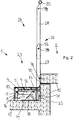
- An in Fig. 1 in the whole with 1 designated tribune has several stepped rising seating and / or standing room rows 2, in each of which a plurality of grandstand seats 3 in the extension direction of the sitting and / or standing room rows 2 are arranged side by side.
- the grandstand seats 3 are each between a first position in which they can be used as a seat ( Fig. 1 ), and a second position in which they can be used as standing space ( Fig. 2 ), adjustable.
- a seat part 5 is attached to a standing platform part 4.
- the seat surface 6 of the seat part 5 faces away from the standing platform part 4.
- the standing platform part 4 is connected on one side to the first socket of a first hinge 7 formed as a first hinge.
- a lug-shaped supporting element 8 to which a backrest 9 is fastened pivotably about an axis 10, is fastened to the standing platform part 4.
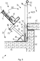
- the axle 10 is arranged such that the backrest 9 substantially without large displacements on the seat surface 6 of the seat part 5 can be placed, as this FIG. 5 can be removed.
- the second socket of the first hinge 7 is fixed to a box section 11, which is fastened to a post-shaped element 12 which is likewise designed as a box profile. At the end facing away from the box section 11, the post-shaped element 12 is attached to the first socket of a second hinge 13.
- the second socket of the second hinge 13 is fixed to a bottom part 14, which is mounted on a grandstand floor 15.
- a locking hook 16 is pivotally mounted, which is actuated by means of a rod 17.
- the locking hook 16 extends through a correspondingly formed opening in the floor platform part 4 and engages behind this. This avoids that the standing platform part 4 can be pivoted about the axis of the first hinge 7.
- a locking rod 18 is fixed, which performs a pivoting movement of the post-shaped member 12 about the axis of the second hinge 13 a corresponding pivoting movement.
- the locking rod 18 engages behind a movable locking element, which is arranged on the bottom part 14. As a result, the post-shaped element 12 is locked in its position.
- the locking hook 16 and the movable locking element are actuated, whereby the respective detents are canceled.
- the standing platform part 4 can be pivoted about the axis of the first hinge 7 and the post-shaped element 12 about the axis of the second hinge 13.
- the corresponding pivoting movements are in Fig. 5 represented by arrows 20, 21.
- the backrest 9 is pivoted about the axis 10 on the seat surface 6 of the seat part 5.
- FIG. 2 can be removed, the standing platform part 4 is supported on the one hand by means of the support elements 8 on the grandstand bottom 15 and on the other hand on a fortified to an end wall 22 of a stage of the tribune 1 support 23.
- FIGS. 1 and 2 Furthermore, one can see by comparing the FIGS. 1 and 2 in that, in the folded state of the grandstand seat 3, the seat part 5 is located virtually unchanged in the horizontal direction at the location where it is arranged in the unfolded state of the grandstand seat 3.
- the horizontal barriers 25 which extend in the direction of the seating and / or standing room rows 2.
- the barrier 25 is preferably designed as a circular cylindrical tube, but may also have a different cross-sectional shape.
- the barriers 25 are attached at both ends via posts 26 on the grandstand floor 15.
- the posts 26 are arranged in the vertical projection on the end walls 22 of the bleachers each between two tribune seats 3, which are arranged side by side in the sitting and / or standing room rows 2, which is located in front of the respective end wall 22.
- the posts 26 are designed telescopically and have a lower, connected to the grandstand bottom 15 tubular post part 27 and an upper, preferably configured as a flat steel post part 28 which is mounted vertically displaceable in an inner cavity of the lower post part 27.
- the barriers 25 can be moved vertically back and forth between a use position and a rest position.
- the barriers 25 are arranged at a height of at least 1.10 m above the level of located behind the barrier 25 stage of the grandstand floor 15.
- the barriers 25 are positioned in the position of use when the grandstand seats 3 are used as standing room or standing platforms.
- the barriers 25 are below their position of use, and at a distance of about 5 to 10 cm above the upper edge of the backrests 9 of the grandstand seats 3, which are located in front of the barrier 25 sitting and / or standing row 2 , It is between the barrier 25 and the grandstand bottom 15 of the located behind the barrier 25 sitting and / or standing row 2 a space 29 is formed ( Fig. 3 ).
- the barriers 25 are positioned in the rest position when the grandstand seats 3 are used as seats.
- a lower portion of the lower post parts 27 is each connected to a mounting flange 30 which is arranged on the end wall 22 of the stand floor 15 and is screwed by means of fastening elements 31, such as screws, bolts or the like with the end wall 22.
- the top posts are 28 is disposed with its lower end in the portion of the lower post parts 27, which is located in front of the end wall 22.
- the both sides of the grandstand seats 3 arranged lower post parts 27 of a breakwater 24 are connected to each other at its upper end by a horizontal cross-beam 32. How out Fig. 5 it can be seen, the barrier 25 is in the rest position on the cross-beam 32.
- Fig. 3 it can be seen that the arranged in the individual seating and / or standing room rows 2 tribune seats 3 are offset in a grid 33 to each other and that behind each tribune seat 3 each have a breakwater 24 is arranged centrally to the grandstand seat 3.
- the lower post parts 27 of these breakwater 24 are mounted at the same height, ie the barriers 25 are in their position of use at the same level. The same applies to the rest position of the seating and / or standing row 2 associated barriers 25.
- the width of the barriers 25 corresponds to the grid dimension 33 of the grandstand seats 3.
- an extension piece 34 can be attached laterally to the first or the last upper post part 28 of a breakwater row, which continues the breakwater row in the extension direction of the rows of seats and / or standing rows 2.
- the extension piece 34 has two in the extension direction of the sitting and / or standing room rows 2 arranged leg portions 35 and a C-shaped interconnecting crosspiece 36. The remote from the crosspiece 36 ends of the leg portions 35 are connected by a connecting flange 37, which is screwed to the first or last upper post part 28 of the breakwater series.
- the length 19, which has the extension piece 34 in the extension direction of the rows of seats and / or standing room 2 is smaller than the grid 33rd
- the posts 26 have for this purpose at the upper end of their lower post parts 27 and at an upper and a lower portion of the upper post parts 28 to the in Fig. 3 each with fürgangslochungen on 38 designated locations.
- locking screws not shown in the drawing are arranged, which pass through the through holes of the lower post part 27 and a through-hole of each of the two engaging in the inner cavity of the lower post part 27 upper post parts 28.
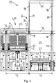
- Fig. 7 to 9 show a further embodiment in which the actual grandstand seats 3 the in Fig. 1 to 6 illustrated grandstand seats 3 correspond, so far as the local description for the Fig. 7 to 9 applies accordingly.
- a breakwater 24 is arranged in each case at the back of each tribune seat 3, which has a horizontal barrier 25 which extends in the direction of the seating and / or standing row 2 and is positioned approximately centrally to the grandstand seat 3 in the extension direction.
- the pitch of the barriers 25 is consistent with the grid dimension 33 of the grandstand seats 3.
- Each tribune seat 3, behind the spectator seats are arranged, which can be used as a standing room, so a separate breakwater is assigned.
- Each barrier 25 is connected in each case at its left end via a left sliding guide and at its right end via a right sliding guide with the end wall 22 of the stepped grandstand floor 15.
- the left sliding guide on the left and the right sliding guide on the right side of the grandstand seat 3 next to or behind the backrest 9 is arranged.
- the slide guides are each configured as telescoping posts 26L, 26R having a lower tubular post part 27L, 27R connected to the end wall 22 and an upper post part 28L, 28R vertically slidably supported in an inner cavity of the lower post part 27L, 27R associated therewith is.
- Right-hand barrier 25 is in the position of use, in which it is located at a height of at least 1.10 m above the level of the located behind the barrier 25 stage of the grandstand floor 15. In this position, the barriers 25 are positioned when the grandstand seats 3 are used as standing room or standing platforms.
- barriers 25 are in the rest position, which is located below the position of use at a small distance to the upper edge of the backrests 9 of the grandstand seats 3. In this position, the barriers 25 are positioned when the grandstand seats 3 are used as seats.
- a lower portion of the lower post parts 27L, 27R is respectively connected to a mounting flange 30L, 30R anchored to the end wall 22.
- the lower post parts 27 L, 27 R of a breakwater 24 arranged on both sides of the stand seats 3 are connected to each other at their upper end by a horizontal cross-beam 32.
- Fig. 8 points in the middle of Fig. 7 illustrated breakwater 24 at the end of its barrier 25, the in Fig. 7 Right mapped breakwater 24 faces, a centering 39 on.
- the centering element 39 is connected via a connecting piece 40 fixed to the right upper post portion 28 R of the center of Fig. 7 illustrated breakwater 24 connected.
- the Centering element 39 is designed as a centering pin which extends in the vertical direction and is secured at its lower end to the connecting piece 40. Towards its upper, free end, the centering element 39 tapers.
- the centering element 39 cooperates with a matching centering counter-element, which is designed as a center hole, in the bottom of the barrier 25 of the in Fig. 7 Shaft breaker 24 shown on the right is introduced such that the centering element 39 and the centering counter-element by relative displacement of in Fig. 7 Central and right shown barriers 25 are mutually movable toward and away from each other and that the centering element 39 and the centering counterpart positively engage with each other when these barriers 25 are aligned in a straight extension to each other.
- each breakwater 24 has a lock which has a cooperating with the left sliding guide, adjustable between an open and a closed position left latch 41L and cooperating with the right sliding guide, adjustable between an open and a closed position right latch 41R.
- the latches 41L, 41R engage in holes, not shown in the drawing, of the respectively associated upper post parts 28L, 28R and in bores of the lower post parts 27L, 27R.
- the lock also has on the cross-beam 32, an adjustable actuator 42 that over rods 43 L, 43 R of a linkage so with the left and right latch 41L, 41R is in drive connection, that in a first position of the actuating element 42, both bars in the open position and in a second position of the actuating element 42, both bars are arranged in the closed position.
- the actuator 42 is rotatably mounted on the cross-beam 32 and has a tool attachment 44 for a wrench, such as a square wrench.
- the rods 43L, 43 of the linkage are each hinged at one end thereof to a bearing point of the actuator 42 off the axis of rotation of the actuator 42 and at the other end to the latch 41L, 41R associated therewith.
Landscapes
- Engineering & Computer Science (AREA)
- Architecture (AREA)
- Civil Engineering (AREA)
- Structural Engineering (AREA)
- Health & Medical Sciences (AREA)
- Dentistry (AREA)
- General Health & Medical Sciences (AREA)
- Special Chairs (AREA)
- Chairs For Special Purposes, Such As Reclining Chairs (AREA)
Claims (13)
- Tribune (1) comprenant plusieurs rangées de places assises et/ou de places debout (2), dans laquelle, dans au moins une rangée de places assises et/ou de places debout (2) est prévue au moins une place de spectateur au niveau de laquelle est monté un siège de tribune (3) associé au plancher de la tribune (15), qui peut être déplacé entre une première position dans laquelle il peut être utilisé comme place assise et une deuxième position dans laquelle la place de spectateur peut être utilisée comme place debout, et comprenant au moins une barrière anti-panique (24) disposée entre la place de spectateur et une rangée supplémentaire de places assises et/ou de places debout (2) se trouvant derrière elle, laquelle barrière anti-panique présente au moins une barrière (25) s'étendant dans la direction des rangées de places assises et/ou de places debout (2), la barrière (25) pouvant être déplacée au moyen d'un dispositif de réglage entre une position d'utilisation et une position de repos dans laquelle la barrière (25) est disposée plus près du plancher de la tribune (15) que dans la position d'utilisation, caractérisée en ce que le dispositif de réglage présente au moins un guide coulissant au moyen duquel l'au moins une barrière (25) peut être déplacée verticalement entre la position d'utilisation et la position de repos, et en ce que l'au moins une barrière (25), dans la position de repos, est espacée du plancher de la tribune (15) de telle sorte qu'entre la barrière (25) et le plancher de la tribune (15) soit formé un espace libre (29).
- Tribune (1) selon la revendication 1, caractérisée en ce que la place assise (3) présente un dossier (9), et en ce que la barrière (25), dans la position de repos, est disposée à côté du bord supérieur du dossier (9).
- Tribune (1) selon la revendication 1 ou 2, caractérisée en ce que le guide coulissant est réalisé sous forme de guide télescopique.
- Tribune (1) selon la revendication 3, caractérisée en ce que la barrière anti-panique (24) présente au moins un poteau (26) qui présente une partie de poteau inférieure (27) connectée au plancher de tribune (15) et une partie de poteau supérieure (28) connectée à la barrière (25), en ce que la partie de poteau inférieure (27) est réalisée sous forme tubulaire avec une partie creuse intérieure et la partie de poteau supérieure (28) est supportée de manière déplaçable verticalement dans la partie creuse intérieure de la partie de poteau inférieure (27) .
- Tribune (1) selon la revendication 4, caractérisée en ce que, dans une rangée de places assises et/ou de places debout (2) sont disposées l'une à côté de l'autre au moins une première et une deuxième place de spectateur, en ce qu'au niveau de la première place de spectateur est monté un premier siège de tribune (3) et au niveau de la deuxième place de spectateur est monté un deuxième siège de tribune (3), en ce que derrière la première place de spectateur est prévue une première barrière anti-panique (24) présentant une première barrière (25) et derrière la deuxième place de spectateur est prévue une deuxième barrière anti-panique (24) présentant une deuxième barrière (25), en ce qu'entre le premier et le deuxième siège de tribune (3) est disposée une partie de poteau inférieure tubulaire (27) dans laquelle sont supportées de manière déplaçable verticalement deux parties de poteau supérieures (28) décalées l'une par rapport à l'autre dans la direction d'étendue de la première rangée de places assises et/ou de places debout (2), et en ce que l'une des parties de poteau supérieures (28) est connectée à la première barrière (25) et l'autre partie de poteau supérieure (28) est connectée à la deuxième barrière (25).
- Tribune (1) selon l'une quelconque des revendications 1 à 5, caractérisée en ce que dans une première rangée de places assises et/ou de places debout (2) est disposée une pluralité de sièges de tribune (3) les uns à côté des autres, qui sont décalés les uns par rapport aux autres dans la direction d'étendue de la rangée de places assises et/ou de places debout (2) suivant un quadrillage (33), en ce qu'entre la première rangée de places assises et/ou de places debout (2) et une deuxième rangée de places assises et/ou de places debout (2) se trouvant derrière elle sont disposées les unes à côté des autres une pluralité de barrières anti-panique (24) dans la direction d'étendue de la rangée de places assises et/ou de places debout (2), et en ce que les barrières anti-panique (24) sont décalées les unes par rapport aux autres dans le quadrillage (33) des sièges de tribune (3).
- Tribune (1) selon l'une quelconque des revendications 1 à 5, caractérisée en ce qu'au moins une première barrière anti-panique présentant une première barrière (25) et une deuxième barrière anti-panique (24) présentant une deuxième barrière (25) sont décalées l'une par rapport à l'autre dans la direction d'étendue d'une rangée de places assises et/ou de places debout (2) disposée devant les barrières anti-panique (24), de telle sorte qu'une rangée de barrières anti-panique soit formée, en ce qu'au niveau de l'extrémité de la première barrière (25) tournée vers la deuxième barrière (25), un élément de centrage (39) est connecté à la première barrière (25) et au niveau de l'extrémité de la deuxième barrière (25) tournée vers la première barrière (25), un élément de centrage conjugué adapté à l'élément de centrage (39) est connecté à la deuxième barrière (25) et en ce que l'élément de centrage (25) et l'élément de centrage conjugué sont réalisés de telle sorte qu'ils puissent être déplacés l'un vers l'autre et à l'écart l'un de l'autre par un déplacement relatif des barrières (25) les unes par rapport aux autres et en ce que l'élément de centrage (39) et l'élément de centrage conjugué s'engagent l'un dans l'autre par engagement par correspondance de formes lorsque les barrières (25) sont alignées les unes avec les autres.
- Tribune (1) selon la revendication 7, caractérisée en ce que l'élément de centrage (39) est réalisé sous forme de goupille de centrage se rétrécissant de préférence vers son extrémité libre et l'élément de centrage conjugué est réalisé sous forme de perçage ou de renfoncement ajusté à la goupille de centrage.
- Tribune (1) selon l'une quelconque des revendications 1 à 8, caractérisée en ce que plusieurs barrières anti-panique (24) sont décalées les unes par rapport aux autres dans la direction d'étendue d'une rangée de places assises et/ou de places debout (2) disposée devant les barrières anti-panique (24), de telle sorte qu'une rangée de barrières anti-panique soit formée, et en ce qu'une première et/ou une dernière barrière anti-panique (24) de la rangée de barrières anti-panique est connectée latéralement à au moins une pièce de prolongement (34) qui prolonge la rangée de barrières anti-panique dans la direction d'étendue et qui, dans la direction d'étendue de la rangée de places assises et/ou de places debout (2), est plus courte que les barrières anti-panique individuelles (24) de la rangée de barrières anti-panique.
- Tribune (1) selon l'une quelconque des revendications 1 à 9, caractérisée en ce que les rangées de places assises et/ou de places debout (2) montent de manière étagée, en ce qu'entre le plancher de la tribune (15) d'une première rangée de places assises et/ou de places debout (2) et le plancher de la tribune (15) d'une deuxième rangée de places assises et/ou de place debout (2) est disposée une paroi frontale (22) et en ce que l'au moins un poteau (26) est fixé à la paroi frontale.
- Tribune (1) selon l'une quelconque des revendications 1 à 10, caractérisée en ce que le dispositif de réglage présente un verrouillage au moyen duquel l'au moins une barrière (25) peut être verrouillée dans la position d'utilisation et/ou dans la position de repos.
- Tribune (1) selon l'une quelconque des revendications 1 à 11, caractérisée en ce que la barrière anti-panique (24) présente une glissière gauche connectée à une région d'extrémité gauche de la barrière (25) et une glissière droite connectée à une région d'extrémité droite de la barrière (25), en ce que le verrouillage présente un verrou gauche (41L) coopérant avec la glissière gauche, pouvant être réglé entre une position d'ouverture et une position de fermeture et un verrou droit (41R) coopérant avec la glissière droite, pouvant être réglé entre une position d'ouverture et une position de fermeture, et en ce que le verrouillage présente un élément d'actionnement réglable (42) qui est en liaison d'entraînement avec le verrou gauche et le verrou droit (41L, 41R) de telle sorte que dans une première position de l'élément d'actionnement (42), les deux verrous (41L, 41R) soient disposés dans la position d'ouverture et dans une deuxième position de l'élément d'actionnement (42), les deux verrous (41L, 41R) soient disposés dans la position de fermeture.
- Tribune (1) selon l'une quelconque des revendications 1 à 12, caractérisée en ce que l'au moins un siège de tribune (3) présente une partie de marchepied (4) sur laquelle est fixée une partie de siège (5) avec un dossier (9) disposé de manière à pouvoir pivoter sur celle-ci, en ce que la partie de marchepied (4) est disposée de manière à pouvoir pivoter au niveau d'au moins un élément en forme de poteau (12) et l'élément en forme de poteau (12) est connecté de manière pivotante au plancher de la tribune (15) au niveau de son extrémité opposée à la partie de marchepied (4).
Priority Applications (1)
| Application Number | Priority Date | Filing Date | Title |
|---|---|---|---|
| PL16167347T PL3090657T3 (pl) | 2015-05-04 | 2016-04-27 | Trybuna z wieloma rzędami miejsc siedzących i/lub stojących i z łamaczem fali |
Applications Claiming Priority (1)
| Application Number | Priority Date | Filing Date | Title |
|---|---|---|---|
| DE102015005552.6A DE102015005552A1 (de) | 2015-05-04 | 2015-05-04 | Tribüne mit mehreren Sitz- und/oder Stehplatzreihen |
Publications (2)
| Publication Number | Publication Date |
|---|---|
| EP3090657A1 EP3090657A1 (fr) | 2016-11-09 |
| EP3090657B1 true EP3090657B1 (fr) | 2018-06-13 |
Family
ID=55862587
Family Applications (1)
| Application Number | Title | Priority Date | Filing Date |
|---|---|---|---|
| EP16167347.0A Active EP3090657B1 (fr) | 2015-05-04 | 2016-04-27 | Tribune avec plusieurs places assise et/ou places debout et avec une barriere anti-panique |
Country Status (4)
| Country | Link |
|---|---|
| EP (1) | EP3090657B1 (fr) |
| DE (1) | DE102015005552A1 (fr) |
| ES (1) | ES2681870T3 (fr) |
| PL (1) | PL3090657T3 (fr) |
Families Citing this family (4)
| Publication number | Priority date | Publication date | Assignee | Title |
|---|---|---|---|---|
| US10925400B2 (en) | 2016-11-29 | 2021-02-23 | Michael CUNNAH | Flexible crowd seating |
| CN107445107A (zh) * | 2017-08-02 | 2017-12-08 | 芜湖昊葛金自动化科技有限公司 | 一种全自动舞台座椅升降系统 |
| CN109057418B (zh) * | 2018-10-09 | 2020-06-26 | 北京电影学院 | 一种集合式表演舞台 |
| AT524307A2 (de) * | 2020-09-02 | 2022-03-15 | Gerhard Steinbrecher | CD-versenkbare Wellenbrecher (geländer) |
Family Cites Families (8)
| Publication number | Priority date | Publication date | Assignee | Title |
|---|---|---|---|---|
| DE553431C (de) * | 1932-06-25 | Emil Gehrhardt | Zerlegbare Zuschauertribuene | |
| DE3619992A1 (de) * | 1986-06-13 | 1987-12-17 | Unibau Gebr Schulte Gmbh & Co | Gelaender |
| DE4324920A1 (de) * | 1993-07-24 | 1995-01-26 | Werner Hansal | Barrierenvorrichtung, insbesondere für Stadiontribünen und Veranstaltungshallen |
| DE20009186U1 (de) * | 2000-05-24 | 2001-07-05 | Abu Shaar, Isam, 35066 Frankenberg | Tribünenstuhl |
| DE20211382U1 (de) * | 2002-07-23 | 2002-09-26 | Domeny, Christian, 73730 Esslingen | Absperrvorrichtung |
| DE202010004302U1 (de) * | 2010-03-26 | 2010-07-01 | Astrid Maier Metall- und Tribünenbau GmbH | Sitz für Tribünen |
| EP2712983A1 (fr) * | 2012-09-29 | 2014-04-02 | INTER+-POL Freie Forschungs- u. Entwicklungsges. f. unfassb. Formate, exper. Proj.,ungesehene Filme dicke u. dünne Bücher, grenzenl. Räume, ....mbH | Tribune avec sièges surélevés |
| DE102012024117B3 (de) * | 2012-12-11 | 2014-01-16 | Astrid Maier Metall- und Tribünenbau GmbH | Stadionbauwerk mit einer Zuschauertribüne |
-
2015
- 2015-05-04 DE DE102015005552.6A patent/DE102015005552A1/de not_active Withdrawn
-
2016
- 2016-04-27 EP EP16167347.0A patent/EP3090657B1/fr active Active
- 2016-04-27 PL PL16167347T patent/PL3090657T3/pl unknown
- 2016-04-27 ES ES16167347.0T patent/ES2681870T3/es active Active
Non-Patent Citations (1)
| Title |
|---|
| None * |
Also Published As
| Publication number | Publication date |
|---|---|
| DE102015005552A1 (de) | 2016-11-10 |
| ES2681870T3 (es) | 2018-09-17 |
| EP3090657A1 (fr) | 2016-11-09 |
| PL3090657T3 (pl) | 2018-11-30 |
Similar Documents
| Publication | Publication Date | Title |
|---|---|---|
| EP3090657B1 (fr) | Tribune avec plusieurs places assise et/ou places debout et avec une barriere anti-panique | |
| EP1571275B1 (fr) | Dispositif pour le montage d'un garde-corps provisoire d'échafaudage | |
| EP4064937B1 (fr) | Meuble en kit | |
| DE102009007877B4 (de) | Klappsitz für eine Steh- und Sitzplatztribüne | |
| EP2468141B1 (fr) | Siège pour tribunes | |
| EP4064939A1 (fr) | Structure de raccordement de tuyau et kit de meuble | |
| DE202015003209U1 (de) | Tribüne mit mehreren Sitz- und/oder Stehplatzreihen | |
| DE202015103730U1 (de) | Untergestell für Bettrahmen und Bett mit Bettrahmen und Untergestell | |
| DE102004063580A1 (de) | Möbelstück mit bewegbarem Möbelsegment | |
| EP3799768B1 (fr) | Siège pliant convertible pour une tribune avec places debout et assise | |
| DE102015017177B4 (de) | Grabenverbau-Einheit | |
| DE602004000559T2 (de) | Geländer mit gekreuzten Stäben für Gerüste | |
| EP1344474A1 (fr) | Lit, notamment lit d'hôpital | |
| EP3323931B1 (fr) | Séchoir à linge permettant d'étendre et de faire sécher le linge | |
| EP2921082A1 (fr) | Meuble destiné à s'asseoir ou s'allonger doté d'un cadre et élément latéral y étant relié | |
| DE3146008C2 (de) | Einsperrgitter für Kurzstand-Rinderställe | |
| DE102016203585A1 (de) | Verstellbare tragkonstruktion, insbesondere für einen podologiestuhl | |
| EP3360443A1 (fr) | Repose-pied réglable en hauteur | |
| DE202010005963U1 (de) | Sitzmöbel, insbesondere Sitzsessel | |
| AT517788A1 (de) | Zusammenklappbare Sitzvorrichtung | |
| DE10044488B4 (de) | Stuhl mit höhenverstellbarem Sitz | |
| DE202022103337U1 (de) | Kraftstation mit einem klappbaren Bodenplattenabschnitt zum Durchführen von Kraftübungen durch einen Nutzer | |
| DE20109280U1 (de) | Steh-/Sitzplatz-Einrichtung | |
| WO2007118590A1 (fr) | Ossature support pour places assise et/ou debout | |
| DE102020126784A1 (de) | Trainingsgerät für das Krafttraining |
Legal Events
| Date | Code | Title | Description |
|---|---|---|---|
| PUAI | Public reference made under article 153(3) epc to a published international application that has entered the european phase |
Free format text: ORIGINAL CODE: 0009012 |
|
| AK | Designated contracting states |
Kind code of ref document: A1 Designated state(s): AL AT BE BG CH CY CZ DE DK EE ES FI FR GB GR HR HU IE IS IT LI LT LU LV MC MK MT NL NO PL PT RO RS SE SI SK SM TR |
|
| AX | Request for extension of the european patent |
Extension state: BA ME |
|
| STAA | Information on the status of an ep patent application or granted ep patent |
Free format text: STATUS: REQUEST FOR EXAMINATION WAS MADE |
|
| 17P | Request for examination filed |
Effective date: 20170509 |
|
| RBV | Designated contracting states (corrected) |
Designated state(s): AL AT BE BG CH CY CZ DE DK EE ES FI FR GB GR HR HU IE IS IT LI LT LU LV MC MK MT NL NO PL PT RO RS SE SI SK SM TR |
|
| REG | Reference to a national code |
Ref country code: DE Ref legal event code: R079 Ref document number: 502016001229 Country of ref document: DE Free format text: PREVIOUS MAIN CLASS: A47C0001160000 Ipc: A47C0001120000 |
|
| GRAP | Despatch of communication of intention to grant a patent |
Free format text: ORIGINAL CODE: EPIDOSNIGR1 |
|
| STAA | Information on the status of an ep patent application or granted ep patent |
Free format text: STATUS: GRANT OF PATENT IS INTENDED |
|
| RIC1 | Information provided on ipc code assigned before grant |
Ipc: E04H 3/24 20060101ALI20171213BHEP Ipc: E04H 3/12 20060101ALI20171213BHEP Ipc: A47C 1/12 20060101AFI20171213BHEP |
|
| INTG | Intention to grant announced |
Effective date: 20180108 |
|
| GRAS | Grant fee paid |
Free format text: ORIGINAL CODE: EPIDOSNIGR3 |
|
| GRAA | (expected) grant |
Free format text: ORIGINAL CODE: 0009210 |
|
| STAA | Information on the status of an ep patent application or granted ep patent |
Free format text: STATUS: THE PATENT HAS BEEN GRANTED |
|
| AK | Designated contracting states |
Kind code of ref document: B1 Designated state(s): AL AT BE BG CH CY CZ DE DK EE ES FI FR GB GR HR HU IE IS IT LI LT LU LV MC MK MT NL NO PL PT RO RS SE SI SK SM TR |
|
| REG | Reference to a national code |
Ref country code: GB Ref legal event code: FG4D Free format text: NOT ENGLISH |
|
| REG | Reference to a national code |
Ref country code: CH Ref legal event code: EP Ref country code: AT Ref legal event code: REF Ref document number: 1007577 Country of ref document: AT Kind code of ref document: T Effective date: 20180615 |
|
| REG | Reference to a national code |
Ref country code: IE Ref legal event code: FG4D Free format text: LANGUAGE OF EP DOCUMENT: GERMAN |
|
| REG | Reference to a national code |
Ref country code: DE Ref legal event code: R096 Ref document number: 502016001229 Country of ref document: DE |
|
| REG | Reference to a national code |
Ref country code: ES Ref legal event code: FG2A Ref document number: 2681870 Country of ref document: ES Kind code of ref document: T3 Effective date: 20180917 |
|
| REG | Reference to a national code |
Ref country code: NL Ref legal event code: MP Effective date: 20180613 |
|
| REG | Reference to a national code |
Ref country code: LT Ref legal event code: MG4D |
|
| PG25 | Lapsed in a contracting state [announced via postgrant information from national office to epo] |
Ref country code: SE Free format text: LAPSE BECAUSE OF FAILURE TO SUBMIT A TRANSLATION OF THE DESCRIPTION OR TO PAY THE FEE WITHIN THE PRESCRIBED TIME-LIMIT Effective date: 20180613 Ref country code: LT Free format text: LAPSE BECAUSE OF FAILURE TO SUBMIT A TRANSLATION OF THE DESCRIPTION OR TO PAY THE FEE WITHIN THE PRESCRIBED TIME-LIMIT Effective date: 20180613 Ref country code: FI Free format text: LAPSE BECAUSE OF FAILURE TO SUBMIT A TRANSLATION OF THE DESCRIPTION OR TO PAY THE FEE WITHIN THE PRESCRIBED TIME-LIMIT Effective date: 20180613 Ref country code: CY Free format text: LAPSE BECAUSE OF FAILURE TO SUBMIT A TRANSLATION OF THE DESCRIPTION OR TO PAY THE FEE WITHIN THE PRESCRIBED TIME-LIMIT Effective date: 20180613 Ref country code: NO Free format text: LAPSE BECAUSE OF FAILURE TO SUBMIT A TRANSLATION OF THE DESCRIPTION OR TO PAY THE FEE WITHIN THE PRESCRIBED TIME-LIMIT Effective date: 20180913 Ref country code: BG Free format text: LAPSE BECAUSE OF FAILURE TO SUBMIT A TRANSLATION OF THE DESCRIPTION OR TO PAY THE FEE WITHIN THE PRESCRIBED TIME-LIMIT Effective date: 20180913 |
|
| PG25 | Lapsed in a contracting state [announced via postgrant information from national office to epo] |
Ref country code: GR Free format text: LAPSE BECAUSE OF FAILURE TO SUBMIT A TRANSLATION OF THE DESCRIPTION OR TO PAY THE FEE WITHIN THE PRESCRIBED TIME-LIMIT Effective date: 20180914 Ref country code: RS Free format text: LAPSE BECAUSE OF FAILURE TO SUBMIT A TRANSLATION OF THE DESCRIPTION OR TO PAY THE FEE WITHIN THE PRESCRIBED TIME-LIMIT Effective date: 20180613 Ref country code: LV Free format text: LAPSE BECAUSE OF FAILURE TO SUBMIT A TRANSLATION OF THE DESCRIPTION OR TO PAY THE FEE WITHIN THE PRESCRIBED TIME-LIMIT Effective date: 20180613 Ref country code: HR Free format text: LAPSE BECAUSE OF FAILURE TO SUBMIT A TRANSLATION OF THE DESCRIPTION OR TO PAY THE FEE WITHIN THE PRESCRIBED TIME-LIMIT Effective date: 20180613 |
|
| PG25 | Lapsed in a contracting state [announced via postgrant information from national office to epo] |
Ref country code: NL Free format text: LAPSE BECAUSE OF FAILURE TO SUBMIT A TRANSLATION OF THE DESCRIPTION OR TO PAY THE FEE WITHIN THE PRESCRIBED TIME-LIMIT Effective date: 20180613 |
|
| PG25 | Lapsed in a contracting state [announced via postgrant information from national office to epo] |
Ref country code: CZ Free format text: LAPSE BECAUSE OF FAILURE TO SUBMIT A TRANSLATION OF THE DESCRIPTION OR TO PAY THE FEE WITHIN THE PRESCRIBED TIME-LIMIT Effective date: 20180613 Ref country code: SK Free format text: LAPSE BECAUSE OF FAILURE TO SUBMIT A TRANSLATION OF THE DESCRIPTION OR TO PAY THE FEE WITHIN THE PRESCRIBED TIME-LIMIT Effective date: 20180613 Ref country code: EE Free format text: LAPSE BECAUSE OF FAILURE TO SUBMIT A TRANSLATION OF THE DESCRIPTION OR TO PAY THE FEE WITHIN THE PRESCRIBED TIME-LIMIT Effective date: 20180613 Ref country code: IS Free format text: LAPSE BECAUSE OF FAILURE TO SUBMIT A TRANSLATION OF THE DESCRIPTION OR TO PAY THE FEE WITHIN THE PRESCRIBED TIME-LIMIT Effective date: 20181013 Ref country code: RO Free format text: LAPSE BECAUSE OF FAILURE TO SUBMIT A TRANSLATION OF THE DESCRIPTION OR TO PAY THE FEE WITHIN THE PRESCRIBED TIME-LIMIT Effective date: 20180613 |
|
| PG25 | Lapsed in a contracting state [announced via postgrant information from national office to epo] |
Ref country code: SM Free format text: LAPSE BECAUSE OF FAILURE TO SUBMIT A TRANSLATION OF THE DESCRIPTION OR TO PAY THE FEE WITHIN THE PRESCRIBED TIME-LIMIT Effective date: 20180613 |
|
| REG | Reference to a national code |
Ref country code: DE Ref legal event code: R097 Ref document number: 502016001229 Country of ref document: DE |
|
| PLBE | No opposition filed within time limit |
Free format text: ORIGINAL CODE: 0009261 |
|
| STAA | Information on the status of an ep patent application or granted ep patent |
Free format text: STATUS: NO OPPOSITION FILED WITHIN TIME LIMIT |
|
| 26N | No opposition filed |
Effective date: 20190314 |
|
| REG | Reference to a national code |
Ref country code: DE Ref legal event code: R082 Ref document number: 502016001229 Country of ref document: DE Representative=s name: HUWER & PARTNER PATENT- UND RECHTSANWAELTE PAR, DE Ref country code: DE Ref legal event code: R081 Ref document number: 502016001229 Country of ref document: DE Owner name: ASTRID MAIER METALL- UND TRIBUENENBAU GMBH, DE Free format text: FORMER OWNER: ASTRID MAIER METALL- UND TRIBUENENBAU GMBH, 76139 KARLSRUHE, DE |
|
| PG25 | Lapsed in a contracting state [announced via postgrant information from national office to epo] |
Ref country code: DK Free format text: LAPSE BECAUSE OF FAILURE TO SUBMIT A TRANSLATION OF THE DESCRIPTION OR TO PAY THE FEE WITHIN THE PRESCRIBED TIME-LIMIT Effective date: 20180613 Ref country code: SI Free format text: LAPSE BECAUSE OF FAILURE TO SUBMIT A TRANSLATION OF THE DESCRIPTION OR TO PAY THE FEE WITHIN THE PRESCRIBED TIME-LIMIT Effective date: 20180613 |
|
| PG25 | Lapsed in a contracting state [announced via postgrant information from national office to epo] |
Ref country code: AL Free format text: LAPSE BECAUSE OF FAILURE TO SUBMIT A TRANSLATION OF THE DESCRIPTION OR TO PAY THE FEE WITHIN THE PRESCRIBED TIME-LIMIT Effective date: 20180613 |
|
| REG | Reference to a national code |
Ref country code: CH Ref legal event code: PL |
|
| REG | Reference to a national code |
Ref country code: BE Ref legal event code: MM Effective date: 20190430 |
|
| PG25 | Lapsed in a contracting state [announced via postgrant information from national office to epo] |
Ref country code: LU Free format text: LAPSE BECAUSE OF NON-PAYMENT OF DUE FEES Effective date: 20190427 Ref country code: MC Free format text: LAPSE BECAUSE OF FAILURE TO SUBMIT A TRANSLATION OF THE DESCRIPTION OR TO PAY THE FEE WITHIN THE PRESCRIBED TIME-LIMIT Effective date: 20180613 |
|
| PG25 | Lapsed in a contracting state [announced via postgrant information from national office to epo] |
Ref country code: CH Free format text: LAPSE BECAUSE OF NON-PAYMENT OF DUE FEES Effective date: 20190430 Ref country code: LI Free format text: LAPSE BECAUSE OF NON-PAYMENT OF DUE FEES Effective date: 20190430 |
|
| PG25 | Lapsed in a contracting state [announced via postgrant information from national office to epo] |
Ref country code: BE Free format text: LAPSE BECAUSE OF NON-PAYMENT OF DUE FEES Effective date: 20190430 |
|
| PG25 | Lapsed in a contracting state [announced via postgrant information from national office to epo] |
Ref country code: TR Free format text: LAPSE BECAUSE OF FAILURE TO SUBMIT A TRANSLATION OF THE DESCRIPTION OR TO PAY THE FEE WITHIN THE PRESCRIBED TIME-LIMIT Effective date: 20180613 |
|
| PG25 | Lapsed in a contracting state [announced via postgrant information from national office to epo] |
Ref country code: IE Free format text: LAPSE BECAUSE OF NON-PAYMENT OF DUE FEES Effective date: 20190427 |
|
| PG25 | Lapsed in a contracting state [announced via postgrant information from national office to epo] |
Ref country code: PT Free format text: LAPSE BECAUSE OF FAILURE TO SUBMIT A TRANSLATION OF THE DESCRIPTION OR TO PAY THE FEE WITHIN THE PRESCRIBED TIME-LIMIT Effective date: 20181015 |
|
| PG25 | Lapsed in a contracting state [announced via postgrant information from national office to epo] |
Ref country code: MT Free format text: LAPSE BECAUSE OF FAILURE TO SUBMIT A TRANSLATION OF THE DESCRIPTION OR TO PAY THE FEE WITHIN THE PRESCRIBED TIME-LIMIT Effective date: 20180613 Ref country code: HU Free format text: LAPSE BECAUSE OF FAILURE TO SUBMIT A TRANSLATION OF THE DESCRIPTION OR TO PAY THE FEE WITHIN THE PRESCRIBED TIME-LIMIT; INVALID AB INITIO Effective date: 20160427 |
|
| REG | Reference to a national code |
Ref country code: AT Ref legal event code: MM01 Ref document number: 1007577 Country of ref document: AT Kind code of ref document: T Effective date: 20210427 |
|
| PG25 | Lapsed in a contracting state [announced via postgrant information from national office to epo] |
Ref country code: MK Free format text: LAPSE BECAUSE OF FAILURE TO SUBMIT A TRANSLATION OF THE DESCRIPTION OR TO PAY THE FEE WITHIN THE PRESCRIBED TIME-LIMIT Effective date: 20180613 |
|
| PG25 | Lapsed in a contracting state [announced via postgrant information from national office to epo] |
Ref country code: AT Free format text: LAPSE BECAUSE OF NON-PAYMENT OF DUE FEES Effective date: 20210427 |
|
| P01 | Opt-out of the competence of the unified patent court (upc) registered |
Effective date: 20230528 |
|
| PGFP | Annual fee paid to national office [announced via postgrant information from national office to epo] |
Ref country code: PL Payment date: 20250319 Year of fee payment: 10 |
|
| PGFP | Annual fee paid to national office [announced via postgrant information from national office to epo] |
Ref country code: DE Payment date: 20250430 Year of fee payment: 10 |
|
| PGFP | Annual fee paid to national office [announced via postgrant information from national office to epo] |
Ref country code: ES Payment date: 20250519 Year of fee payment: 10 Ref country code: GB Payment date: 20250423 Year of fee payment: 10 |
|
| PGFP | Annual fee paid to national office [announced via postgrant information from national office to epo] |
Ref country code: IT Payment date: 20250430 Year of fee payment: 10 |
|
| PGFP | Annual fee paid to national office [announced via postgrant information from national office to epo] |
Ref country code: FR Payment date: 20250422 Year of fee payment: 10 |