EP3089331A1 - Moteur et son procédé de fabrication - Google Patents
Moteur et son procédé de fabrication Download PDFInfo
- Publication number
- EP3089331A1 EP3089331A1 EP15785543.8A EP15785543A EP3089331A1 EP 3089331 A1 EP3089331 A1 EP 3089331A1 EP 15785543 A EP15785543 A EP 15785543A EP 3089331 A1 EP3089331 A1 EP 3089331A1
- Authority
- EP
- European Patent Office
- Prior art keywords
- coil bobbin
- coil
- wire
- bobbin unit
- phase
- Prior art date
- Legal status (The legal status is an assumption and is not a legal conclusion. Google has not performed a legal analysis and makes no representation as to the accuracy of the status listed.)
- Granted
Links
- 238000004519 manufacturing process Methods 0.000 title claims abstract description 14
- 238000004804 winding Methods 0.000 claims abstract description 98
- 230000007935 neutral effect Effects 0.000 claims abstract description 70
- 238000005520 cutting process Methods 0.000 claims abstract description 67
- 238000000034 method Methods 0.000 claims description 32
- 239000012212 insulator Substances 0.000 description 31
- WABPQHHGFIMREM-UHFFFAOYSA-N lead(0) Chemical compound [Pb] WABPQHHGFIMREM-UHFFFAOYSA-N 0.000 description 18
- 230000008878 coupling Effects 0.000 description 16
- 238000010168 coupling process Methods 0.000 description 16
- 238000005859 coupling reaction Methods 0.000 description 16
- 238000003780 insertion Methods 0.000 description 14
- 230000037431 insertion Effects 0.000 description 14
- 230000008569 process Effects 0.000 description 10
- 230000004888 barrier function Effects 0.000 description 9
- 239000000463 material Substances 0.000 description 7
- 230000005415 magnetization Effects 0.000 description 6
- 239000000758 substrate Substances 0.000 description 6
- 239000004020 conductor Substances 0.000 description 3
- 239000012777 electrically insulating material Substances 0.000 description 3
- 239000012811 non-conductive material Substances 0.000 description 3
- XEEYBQQBJWHFJM-UHFFFAOYSA-N Iron Chemical compound [Fe] XEEYBQQBJWHFJM-UHFFFAOYSA-N 0.000 description 2
- 238000005452 bending Methods 0.000 description 2
- 238000006243 chemical reaction Methods 0.000 description 2
- 239000010949 copper Substances 0.000 description 2
- 230000003993 interaction Effects 0.000 description 2
- 239000000696 magnetic material Substances 0.000 description 2
- RYGMFSIKBFXOCR-UHFFFAOYSA-N Copper Chemical compound [Cu] RYGMFSIKBFXOCR-UHFFFAOYSA-N 0.000 description 1
- 229910017767 Cu—Al Inorganic materials 0.000 description 1
- 229910000831 Steel Inorganic materials 0.000 description 1
- 229910000746 Structural steel Inorganic materials 0.000 description 1
- XAGFODPZIPBFFR-UHFFFAOYSA-N aluminium Chemical compound [Al] XAGFODPZIPBFFR-UHFFFAOYSA-N 0.000 description 1
- 229910052782 aluminium Inorganic materials 0.000 description 1
- 239000002131 composite material Substances 0.000 description 1
- 239000000470 constituent Substances 0.000 description 1
- 230000008094 contradictory effect Effects 0.000 description 1
- 229910052802 copper Inorganic materials 0.000 description 1
- 238000009826 distribution Methods 0.000 description 1
- 230000000694 effects Effects 0.000 description 1
- 230000005611 electricity Effects 0.000 description 1
- 230000004907 flux Effects 0.000 description 1
- 229910052742 iron Inorganic materials 0.000 description 1
- 239000007769 metal material Substances 0.000 description 1
- 230000000149 penetrating effect Effects 0.000 description 1
- 238000003825 pressing Methods 0.000 description 1
- 229920005989 resin Polymers 0.000 description 1
- 239000011347 resin Substances 0.000 description 1
- 229910052709 silver Inorganic materials 0.000 description 1
- 239000004332 silver Substances 0.000 description 1
- 238000005476 soldering Methods 0.000 description 1
- 238000000638 solvent extraction Methods 0.000 description 1
- 229910001220 stainless steel Inorganic materials 0.000 description 1
- 239000010935 stainless steel Substances 0.000 description 1
- 239000010959 steel Substances 0.000 description 1
- 229920003002 synthetic resin Polymers 0.000 description 1
- 239000000057 synthetic resin Substances 0.000 description 1
Images


Classifications
-
- H—ELECTRICITY
- H02—GENERATION; CONVERSION OR DISTRIBUTION OF ELECTRIC POWER
- H02K—DYNAMO-ELECTRIC MACHINES
- H02K3/00—Details of windings
- H02K3/04—Windings characterised by the conductor shape, form or construction, e.g. with bar conductors
- H02K3/28—Layout of windings or of connections between windings
-
- H—ELECTRICITY
- H02—GENERATION; CONVERSION OR DISTRIBUTION OF ELECTRIC POWER
- H02K—DYNAMO-ELECTRIC MACHINES
- H02K15/00—Methods or apparatus specially adapted for manufacturing, assembling, maintaining or repairing of dynamo-electric machines
- H02K15/0056—Manufacturing winding connections
- H02K15/0068—Connecting winding sections; Forming leads; Connecting leads to terminals
-
- H—ELECTRICITY
- H02—GENERATION; CONVERSION OR DISTRIBUTION OF ELECTRIC POWER
- H02K—DYNAMO-ELECTRIC MACHINES
- H02K15/00—Methods or apparatus specially adapted for manufacturing, assembling, maintaining or repairing of dynamo-electric machines
- H02K15/04—Methods or apparatus specially adapted for manufacturing, assembling, maintaining or repairing of dynamo-electric machines of windings, prior to mounting into machines
- H02K15/0435—Wound windings
-
- H—ELECTRICITY
- H02—GENERATION; CONVERSION OR DISTRIBUTION OF ELECTRIC POWER
- H02K—DYNAMO-ELECTRIC MACHINES
- H02K3/00—Details of windings
- H02K3/04—Windings characterised by the conductor shape, form or construction, e.g. with bar conductors
- H02K3/18—Windings for salient poles
-
- H—ELECTRICITY
- H02—GENERATION; CONVERSION OR DISTRIBUTION OF ELECTRIC POWER
- H02K—DYNAMO-ELECTRIC MACHINES
- H02K3/00—Details of windings
- H02K3/32—Windings characterised by the shape, form or construction of the insulation
- H02K3/38—Windings characterised by the shape, form or construction of the insulation around winding heads, equalising connectors, or connections thereto
-
- H—ELECTRICITY
- H02—GENERATION; CONVERSION OR DISTRIBUTION OF ELECTRIC POWER
- H02K—DYNAMO-ELECTRIC MACHINES
- H02K3/00—Details of windings
- H02K3/46—Fastening of windings on the stator or rotor structure
- H02K3/48—Fastening of windings on the stator or rotor structure in slots
-
- H—ELECTRICITY
- H02—GENERATION; CONVERSION OR DISTRIBUTION OF ELECTRIC POWER
- H02K—DYNAMO-ELECTRIC MACHINES
- H02K3/00—Details of windings
- H02K3/46—Fastening of windings on the stator or rotor structure
- H02K3/52—Fastening salient pole windings or connections thereto
- H02K3/521—Fastening salient pole windings or connections thereto applicable to stators only
- H02K3/522—Fastening salient pole windings or connections thereto applicable to stators only for generally annular cores with salient poles
-
- H—ELECTRICITY
- H02—GENERATION; CONVERSION OR DISTRIBUTION OF ELECTRIC POWER
- H02K—DYNAMO-ELECTRIC MACHINES
- H02K15/00—Methods or apparatus specially adapted for manufacturing, assembling, maintaining or repairing of dynamo-electric machines
- H02K15/08—Forming windings by laying conductors into or around core parts
- H02K15/095—Forming windings by laying conductors into or around core parts by laying conductors around salient poles
Definitions
- a motor that is a machine capable of converting electrical energy into a rotational force may include a stator and a rotor.
- the rotor is configured to electromagnetically interact with the stator and may be rotated by a force acting between a magnetic field and current flowing through a coil.
- a magnetic field formed for an electromagnetic interaction between the rotor and the stator may include a magnetic field formed by a permanent magnet and a magnetic field formed by current flowing through a coil.
- the magnetic field formed by the current flowing through the coil may be determined by current flowing in the coil and the number of windings.
- the coil is formed by winding a wire on a coil bobbin unit.
- the wires need to be wound individually on each of the teeth.
- a method of manufacturing a motor includes sequentially winding a wire on each of a plurality of coil bobbin unit groups of a stator, cutting the wire at a cutting point to form a parallel pattern, and connecting one end of the cut wire to a neutral point port and connecting the other end of the cut wire to a driving point port.
- the wire may be cut at a cutting point adjacent to a first coil bobbin unit of each coil bobbin unit group on which the wire is first wound and a last coil bobbin unit of the coil bobbin unit group on which the wire is last wound.
- a motor according to an embodiment of the present disclosure will be described with reference to FIG. 1 .
- the rotor 200 which is a device acquiring a rotational force of the motor 100 by using attraction and repulsion between a magnetic field formed by the permanent magnet 280 and a magnetic field formed in the teeth 332 of the stator 330, is disposed in the stator 330.
- a first rotor housing 290a and a second rotor housing 290b may be disposed on the lateral surface of the rotor 200, and a third rotor housing 290c may be disposed on the axial surface of the rotor 200.
- the rotor 200 may include a rotor core, the permanent magnet 280, and a balancer.
- the rotor core may include four permanent magnets 280 in consideration of iron loss due to high-speed drive, switching frequency of an inverter, and other reasons.
- the four permanent magnets 280 may be disposed at four first connection grooves of the rotor core such that one of the permanent magnet 280 has a polarity opposite to a pair of permanent magnets 280 adjacent to the permanent magnet 280.
- the shaft 800 may be inserted into the center of the rotor core.
- the number of the first connection protrusions may be determined to correspond to the number of the first connection grooves of the rotor core or may be determined to correspond to the number of the permanent magnets 280 ( FIGS. 2 and 3 ).
- four first connection protrusions may be formed in a protruding shape from the center of rotation toward the circumference to the outer circumferential surface of the rotor core.
- a fixing structure may be formed on the outer circumferential surface of the rotor 200 including the rotor core and the permanent magnet 280 coupled with each other.
- the fixing structure may fix the permanent magnet 280 ( FIGS. 2 and 3 ) coupled with the rotor core not to be displaced.
- the fixing structure may be formed of structural steel such as stainless steel (SUS), heat shrinkable tube, high-strength plastic, and the like.
- any other material capable of fixing the permanent magnet 280 ( FIGS. 2 and 3 ) coupled with the rotor core not to be displaced therefrom may be used to form the fixing structure.
- the rotor 200 generates a rotational force via interaction between a magnetic field formed by the permanent magnet 280 disposed in the rotor 200 and a magnetic field formed by driving power supplied to the coil 500 and transmits the generated rotational force to the shaft 800.
- the bus bar assembly 605 is a connection member 600 configured to connect a driving point P and a neutral point N of a wire led out from the coil 500 are respectively electrically connected to a driving point port PP and a neutral point port NP when coupled to the stator 330.
- the harness connector assembly 700 includes harness connector pins 720 coupled to a driving point P and a neutral point N of a wire led out from the coil 500, and the coupled harness connector pins 720 may be coupled to pin mounting portions 710.
- the driving point P of the wire led out from the coil 500 may be electrically connected to the driving point port PP and the neutral point N thereof may be electrically connected to the neutral point port NP.
- FIG. 5 is a diagrammatic representation of FIG. 5 .
- connection member 600 may include a bus bar assembly 605 and a harness connector assembly 700.
- connection member 600 is not limited to the bus bar assembly 605 or the harness connector assembly 700, and any other various types of connection members to connect the driving point P and the neutral point N of the coil 500 respectively to the driving point port PP and the neutral point port NP may be used as the connection member 600.
- the bus bar assembly 605 may include a bus bar terminal 640 connecting a wire forming the coil 500 with an external driving circuit, a bus bar group 610 electrically connecting three driving points P and three neutral points N respectively with three driving point ports PP and three neutral point ports NP, a bus bar housing 620 accommodating the bus bar group 610, and a bus bar housing cover 630 covering a top portion of the bus bar housing 620.
- the bus bar terminal 640 may include a lead wire 641 extending the coil 500 included in the stator 330 outward and a terminal-binding terminal 643 bound to the external driving circuit.
- One end of the lead wire 641 is coupled to the terminal-binding terminal 643, and the other end of the lead wire 641 is coupled to the bus bar housing cover 630.
- the terminal-binding terminal 643 is disposed at one end of the lead wire 641 and allows the coil 500 extending outward by the lead wire 641 to be electrically connected to the external driving circuit.
- the bus bar group 610 may include a first bus bar 611, a second bus bar 612, a third bus bar 613, and a fourth bus bar 614 having arc shapes of concentric circles.
- each of the first to fourth bus bars 611, 612, 613, and 614 may be formed of a conductive material.
- each of the first to fourth bus bars 611, 612, 613, and 614 may have a width in the central axial direction of the concentric circle greater than a width in a radial direction in order to efficiently form an arc shape.
- Each of the first to fourth bus bars 611, 612, 613, and 614 may include a bus bar extension unit 616 extending the coil bobbin unit 409, which is connected to a wire constituting the coil 500 of the stator 330, from each of the first to fourth bus bars 611, 612, 613, and 614 to the outer circumferential surface of the bus bar housing 620, and a terminal coupling unit 617 coupling each of the first to fourth bus bars 611, 612, 613, and 614 with the lead wire 641.
- the coil bobbin unit 409 extends from each of the first to fourth bus bars 611, 612, 613, and 614 in a radial direction by the bus bar extension unit 616 and is disposed at an outer side of the bus bar housing 620.
- the terminal coupling unit 617 is formed by bending one end of each of the first to fourth bus bars 611, 612, 613, and 614 in a radial and is coupled to the lead wire 641.
- the first bus bar 611 has an arc shape of a circle with a first radius and disposed at the outermost portion of the bus bar group 610.
- the second bus bar 612, the third bus bar 613, and the fourth bus bar 614 respectively have arc shapes of circles with a second radius, a third radius, and a fourth radius.
- the second bus bar 612, the third bus bar 613, and the fourth bus bar 614 may be disposed in the order of the second bus bar 612, the third bus bar 613, and the fourth bus bar 614 from the outside of the bus bar group 610, and the fourth bus bar 614 may be disposed at the innermost portion of the bus bar group 610.
- the second bus bar 612, the third bus bar 613, and the fourth bus bar 614 may respectively include a U-phase driving point U, a V-phase driving point V, and a W-phase driving point W and may include three driving point ports PP.
- each of the second bus bar 612, the third bus bar 613, and the fourth bus bar 614 may include 3 driving point ports PP.
- the bus bar housing 620 has a hollow cylindrical shape, includes a housing outer wall 621 and a housing inner wall 622, and accommodates the bus bar group 610 between the housing outer wall 621 and the housing inner wall.
- the bus bar housing 620 may be formed of a non-conductive material such as a resin to insulate each of the first to fourth bus bars 611, 612, 613, and 614 included in the bus bar group 610.
- An annular barrier wall 623 is disposed between the housing outer wall 621 and the housing inner wall 622 to isolate the first bus bar 611, the second bus bar 612, the third bus bar 613, and the fourth bus bar 614 from one another.
- the annular barrier wall 623 may include a first annular barrier wall 623a isolating the first bus bar 611 from the second bus bar 612, a second annular barrier wall 623b isolating the second bus bar 612 from the third bus bar 613, and a third annular barrier wall 623c isolating the third bus bar 613 from the fourth bus bar 614.
- annular barrier wall 623 may have a height greater than those of the first to fourth bus bars 611, 612, 613, and 614 such that the bus bar extension unit 616 extending from each of the first to fourth bus bars 611, 612, 613, and 614 in a radial direction does not contact each of the first to fourth bus bars 611, 612, 613, and 614.
- the first bus bar 611, the second bus bar 612, the third bus bar 613, and the fourth bus bar 614 are disposed in the form of being isolated from one another by the annular barrier wall 623.
- first bus bar 611, the second bus bar 612, the third bus bar 613, and the fourth bus bar 614 may be insulated from one another by the annular barrier wall 623.
- a stator hook bar 626 and a cover hook bar 627 are disposed at the housing outer wall 621 along the outer circumferential surface of the bus bar housing 620, and a first guide plate 628 protruding from the bus bar housing 620 in a radial direction is provided.
- stator hook bar 626 and the cover hook bar 627 are alternately disposed along the outer circumferential surface of the bus bar housing 620, and the first guide plate 628 is disposed between the stator hook bar 626 and the cover hook bar 627.
- stator hook 626a having a greater diameter than the stator hook bar 626 is disposed at a lower portion of the stator hook bar 626 and couples the bus bar assembly 605 with the stator 330.
- a cover guide bar is integrated with the stator hook bar 626 within the stator hook bar 626.
- the cover guide bar is disposed to correspond to a cover guide groove 636 formed at the bus bar housing cover 630 and guides the bus bar housing cover 630 such that the bus bar housing cover 630 is located at an appropriate position of the bus bar housing 620.
- the cover hook bar 626 is disposed on the surface of the housing outer wall 621 in the central axial direction of the bus bar housing 620.
- a cover hook 627a having a cover hook slope 627b is formed at an upper portion of the cover hook bar 627 and couples the bus bar housing cover 630 with the bus bar housing 620.
- the bus bar housing cover 630 may move toward a binding position along the cover hook slope 627b of the cover hook 627a. While the bus bar housing cover 630 moves toward the binding position along the cover hook slope 627b, the cover hook bar 627 is inclined in a radial direction of the bus bar housing 620.
- bus bar housing cover 630 is held by the cover hook 627a, the bus bar housing cover 630 is not accidentally separated from the bus bar housing 620.
- the first guide plate 628 protrudes from the housing outer wall 621 of the bus bar housing 620 in a radial direction, and a wire guide groove 628a that guides a wire constituting the coil 500 of the stator 330 is disposed at one portion of the first guide plate 628.
- the wire guide groove 628a bends a wire constituting the coil 500 of the stator 330 toward the coil bobbin unit 409 of the bus bar. In this regard, the wire guide groove 628a prevents the wire from protruding outward from the stator 330 by bending the wire toward the circumference of the stator 330.
- the bus bar housing cover 630 has a hollow annular shape.
- the bus bar housing cover 630 may be formed of a non-conductive material as in the bus bar housing 620.
- a terminal insertion groove 631 for coupling the bus bar terminal 640 with the bus bar assembly 605 is disposed on the inner circumferential surface of the bus bar housing cover 630 at a position corresponding to the terminal coupling unit 617 of the bus bar group 610.
- the lead wire 641 of the bus bar terminal 640 is inserted into the terminal insertion groove 631 and coupled to the terminal coupling unit 617 of the bus bar group 610.
- the cover guide groove 636 is disposed on the outer circumferential surface of the bus bar housing cover 630 at a position corresponding to the stator hook bar 626 of the bus bar housing 620, so that the bus bar housing cover 630 is mounted at an appropriate position of the bus bar housing 620.
- FIG. 5 is an exploded view illustrating the harness connector assembly 700.
- the harness connector assembly 700 is formed to correspond to a substrate connector attached to a PCB of a driving circuit and is connected to the driving circuit thereby transmitting driving power required to drive the motor 100 to the coil 500.
- the harness connector assembly 700 may include a harness connector pin 720 coupled to one end of a wire led out from the coil 500 and a harness connector 710 connected to the substrate connector by fixing the harness connector pin 720.
- the harness connector pin 720 may be coupled to the lead wire led out from the coil 500 to fix the lead wire to the harness connector 710.
- a first coupling protrusion is disposed at one side of the harness connector pin 720, and the first coupling protrusion may be fixed to a first coupling groove disposed at one side of the harness connector 710.
- the harness connector pin 720 may be coupled to the lead wire led out from the coil 500 by soldering or by pressing the harness connector pin 720 in which the lead wire is inserted.
- various other methods of electrically connecting the harness connector pin 720 with the lead wire while having mechanical stability may also be used to connect the lead wire with the harness connector pin 720.
- the harness connector pin 720 may be formed of an electrically conductive material to transmit driving power received from the driving circuit to the lead wire.
- the harness connector pin 720 may be formed of silver or lead.
- Various other electrically conductive materials may also be used to form the harness connector pin 720.
- the harness connector 710 is formed to correspond to the substrate connector attached to the PCB of the driving circuit, receives the driving power from the driving circuit, and transmits the driving power to each coil 500 through the harness connector pin 720 and the lead wire.
- the harness connector 710 has three second coupling grooves at the bottom surface for electrical connection with the substrate connector, and the substrate connector includes three second coupling protrusions corresponding to the second coupling grooves.
- the harness connector 710 and the substrate connector may be electrically connected with each other.
- the harness connector 710 may include a pin mounting portion 712.
- Three pin mounting portions 712 are formed on the top surface of the harness connector 710 respectively providing space into which the harness connector pin 720 coupled to the lead wire is inserted and fixed.
- the harness connector 710 may be formed of an electrically insulating material to prevent leakage of current flowing through the lead wire, the harness connector pin 720, and the second coupling protrusion.
- the harness connector 710 may be formed of a synthetic resin.
- various other electrically insulating materials may be used to form the harness connector 710.
- the harness connector assembly 700 includes the harness connector pin 720 and the harness connector 710.
- a U-phase wire group 507U may include a first coil wire 517, a fourth coil wire 547, and a seventh coil wire 577
- a V-phase wire group 507V may include a second coil wire 527 a fifth coil wire 557
- a W-phase wire group 507W may include a third coil wire 537, a sixth coil wire 567, and a ninth coil wire 597.
- the three wires of the U-phase wire group 507U are electrically and mechanically connected to a U-phase pin 723
- the three wires of the V-phase wire group 507V are electrically and mechanically connected to a V-phase pin 726
- the three wires of the W-phase wire group 507W are electrically and mechanically connected to a W-phase pin 729.
- Each harness connector pin 720 related to the U-phase, the V-phase, and the W-phase is coupled to the harness connector in a state of being inserted into the pin mounting portion 712. That is, the U-phase pin 723 is coupled to the harness connector 710 in a state of being inserted into a U-phase pin mounting portion 713, the V-phase pin 726 is coupled to the harness connector 710 in a state of being inserted into a V-phase pin mounting portion 716, and the W-phase pin 729 is coupled to the harness connector 710 in a state of being inserted into a W-phase pin mounting portion 719.
- stator according to an exemplary embodiment will be described with reference to FIG. 6 .
- FIG. 6 is an exploded view illustrating a stator according to an embodiment of the present disclosure.
- a stator 330 may include a stator core 331 and an insulator 400.
- the stator core 331 is formed of a magnetic material that may be magnetized by a magnetic field formed by the coil 500 and includes a hollow cylindrical main core 335, teeth 332 protruding inward from the inner circumferential surface of yokes, and fixing grooves 337 coupled to the motor housing 190 to fix the stator 330.
- stator core 331 will be described in more detail with reference to FIGS. 7 and 8 .
- the insulator 400 may include a first insulator 400a and a second insulator 400b and may include a non-conductive material to insulate between the teeth 332 and the coil 500.
- the first insulator 400a is coupled to the bus bar housing 620.
- the first insulator 400a has hook-holding units at one side to correspond to the stator hook bars 626.
- the hook-holding units are disposed at positions corresponding to the stator hook bars 626 along the outer circumferential surface of the first insulator 400a.
- the hook-holding units are disposed at positions corresponding to the slots 333 of the stator core 331. That is, the stator hook bar 626 of the bus bar housing 620, the hook-holding unit of the first insulator 400a, and the slot 333 of the stator core 331 may be disposed to correspond to one another.
- the hook insertion hole has a diameter similar to that of the stator hook bar 626 and smaller than that of the stator hook 626a disposed at one end of the stator hook bar 626.
- the hook-holding unit is partially cut near the hook insertion hole, and thus the stator hook 626a having a larger diameter may be inserted into the hook insertion hole having a smaller diameter through the cut portion of the hook-holding unit.
- stator hook 626a is inserted into the hook insertion hole, the stator hook 626a is not easily separated from the hook insertion hole.
- the coil bobbin units 409 may be disposed at the inner circumferential surface of the first insulator 400a at equal intervals to correspond to positions of teeth 332 of the stator core 331.
- the coil bobbin unit 409 prevents leakage of driving power caused when the wire of the coil 500 contacts with the stator core 331 and provides a place where the coil 500 is located.
- the coil bobbin unit 409 may include a first coil bobbin unit 410 on which a first coil 510 is formed, a second coil bobbin unit 420 on which a second coil 520 is formed, a third coil bobbin unit 430 on which a third coil 530 is formed, a fourth coil bobbin unit 440 on which a fourth coil 540 is formed, a fifth coil bobbin unit 450 on which a fifth coil 550 is formed, a sixth coil bobbin unit 460 on which a sixth coil 560 is formed, a seventh coil bobbin unit 470 on which a seventh coil 570 is formed, an eighth coil bobbin unit 480 on which an eighth coil 580 is formed, and a ninth coil bobbin unit 490 on which a ninth coil 590 is formed.
- first coil bobbin unit 410, the fourth coil bobbin unit 440, and the seventh coil bobbin unit 470 may constitute a first coil bobbin unit group 415
- the second coil bobbin unit 420, the fifth coil bobbin unit 450, and the eighth coil bobbin unit 480 may constitute a second coil bobbin unit group 425
- the third coil bobbin unit 430, the sixth coil bobbin unit 460, and the ninth coil bobbin unit 490 may constitute a third coil bobbin unit group 435.
- a U-phase coil 500U, a V-phase coil 500V, and a W-phase coil 500W to which each of 3-phase driving power is supplied may respectively be located on the first coil bobbin unit group 415, the second coil bobbin unit group 425, and the third coil bobbin unit group 435.
- the first insulator 400a may have a cavity terminal 405 at an outer circumferential surface.
- the cavity terminal 405 provides wiring space to organize the wire lead out from one coil bobbin unit 309 after being wound thereon to be wound around another coil bobbin unit 409.
- the number of the cavity terminals 405 may be adjusted to correspond to the number of the coil bobbin units 409 included in one coil bobbin unit group.
- one coil bobbin unit group includes three coil bobbin units 409 in a 3-phase 9-slot motor 100 as illustrated in FIG. 6 , three cavity terminals 405, i.e., a first cavity terminal 405a, a second cavity terminal 405b, and a third cavity terminal 405c, may be used.
- the first insulator 400a may include a plurality of wire hooks 406 at the outer circumferential surface.
- the wire hook 406 is configured to organize and fix the wire exposed to the outer circumferential surface of the first insulator 400a by using the cavity terminal 405 in order to wind the wire another coil bobbin unit 409. That is, the wire hook 406 may organize and fix the wire led to the inner circumferential surface of the first insulator 400a or led to the outer circumferential surface along a wire hook groove 407 between the cavity terminals 405.
- a wire guide unit 408 may be disposed at both sides of the coil bobbin unit 409 to prevent the wire wound on the coil bobbin unit 409 from being deviated outward.
- the wire guide unit 408 may include an outer wire guide unit 408b disposed at the outer circumferential surface of the first insulator 400a and an inner wire guide unit 408a disposed at the inner circumferential surface of the first insulator 400a.
- the wire guide unit 408 protrudes from the top surface of the coil bobbin unit 409 in the axial direction of the stator 330.
- the wire guide unit 408 bends the wire toward the circumference of the stator 330, thereby preventing the wire from protruding outward or inward from the stator 330.
- FIG. 7 is a cross-sectional view illustrating a stator and a coil.
- FIG. 8 illustrates an appearance of a stator and a coil.
- a stator 330 may include a stator core 331.
- the stator core 331 may serve as a supporting frame to maintain the shape of the stator 330 and may provide space where the coil 500 is located.
- the stator core 331 may include teeth 332, a main core 335, and fixing grooves 337.
- the teeth 332 are located in the stator core 331 divided by the main core 335 thereby partitioning the inner space of the stator core 331 into a plurality of slots 333.
- the teeth 332 may provide places where the coil 500 is located and may be magnetized to an N-pole or an S-pole by a magnetic field formed by power applied to the coil 500.
- each tooth 332 may have a Y-shape and a curved surface adjacent to the rotor 200 among outer surfaces of the tooth 332 for efficient generation of attraction and repulsion with the permanent magnet 280 included in the rotor 200.
- various other structures to provide space where the coil 500 is located and to efficiently generate attraction and repulsion with the permanent magnet 280 may also be used in the teeth 332.
- the main core 335 constitutes a framework of the stator core 331 maintaining the shape of the stator core 331, and a plurality of teeth 332 may be coupled to the main core 335.
- the main core 335 may provide a passage in which a magnetic field is formed such that one tooth 332 magnetized by power may lead to induced magnetization of a pair of teeth 332 adjacent to the tooth 332 to have a polarity opposite to that of the tooth 332 magnetized by power.
- the main core 335 may have a cylindrical shape.
- a plurality of teeth 332 may be disposed at inner portions of the main core 335, and a plurality of fixing grooves 337 may be disposed at outer portions of the main core 335.
- the main core 335 may have various other structures to maintain the shape of the stator core 335 and to locate the teeth 332 and the fixing grooves 337.
- the fixing grooves 337 may provide a fixing force such that the stator 330 is not separated from the motor housing 190 in spite of the rotational force generated by attraction and repulsion between a magnetic field formed by power applied to the coil 500 and a magnetic field formed by the permanent magnet 280.
- the fixing grooves 337 may be formed at an outer barrier wall of the main core 335 to be parallel to the shaft 800 thereby being correspondingly coupled to protrusions of the motor housing 190.
- the fixing groove 337 may have various other shapes to fix the stator 330 to the motor housing 190.
- the stator core 331 including the teeth 332, the main core 335, and the fixing grooves 337 may be magnetized by power applied to the coil 500 and may be formed of a metallic material or a magnetic material efficiently forming a magnetic field for efficient induced magnetization of adjacent teeth 332.
- the stator core 331 may be formed of various other materials magnetized by power applied to the coil 500 and efficiently forming a magnetic field for induced magnetization of adjacent teeth 332.
- the coil 500 is disposed on the coil bobbin unit 409 of the insulator 400 disposed on one tooth 332 of the stator core 331 and may form a magnetic field by power applied thereto. Thus, the coil 500 may magnetize the tooth 332 on which the coil 500 is located.
- the coil 500 may include a first coil 510, a second coil 520, a third coil 530, a fourth coil 540, a fifth coil 550, a sixth coil 560, a seventh coil 570, an eighth coil 580, and a ninth coil 590.
- the first coil 510 is illustrated at an upper portion of FIG. 7
- the second coil 520, the third coil 530, the fourth coil 540, the fifth coil 550, the sixth coil 560, the seventh coil 570, the eighth coil 580, and the ninth coil 590 may be sequentially disposed counter-clockwise.
- a second coil wire 527 that is one end of the wire wound on the second coil 520 and lead out therefrom, a fifth coil wire 557 that is one end of the wire wound on the fifth coil 550 and lead out therefrom, and an eighth coil wire 587 that is one end of the wire wound on the eighth coil 580 and lead out therefrom may be drawn out from the same position.
- the second coil wire 527, the fifth coil wire 557, and the eighth coil wire 587 drawn out from the same position may constitute a V-phase wire group 507V and may be connected to a V-phase driving point port VPP.
- V-phase driving power may be supplied to the V-phase wire group 507V through the V-phase driving point port VPP.
- each of the n U-phase coils 500U is connected to the U-phase driving point port UPP. Since one end of the V-phase coil 500V is a driving point V, one end of each of the n V-phase coils 500V is connected to the V-phase driving point port VPP. Since one end of the W-phase coil 500W is a driving point W, each of the n W-phase coil 500W is connected to the W-phase driving point port WPP. In addition, since the other end of each of the U-phase coil 500U, the V-phase coil 500V, and the W-phase coil 500W is a neutral points N, the other end of each of the 3n coils is connected to the neutral point port NP.
- the wire is wound on the first coil bobbin unit 410 in a direction opposite to that of the fourth coil bobbin unit 440 and the seventh coil bobbin unit 470 by the predetermined number of windings to prepare the first coil 510, and the winding is terminated while setting the end of the wire as a third neutral point N3.
- the predetermined number of windings is a value determined according to output of power of a product to which the motor 100 is applied, target output of power desired by a user or a manufacturer, energy efficiency, and the like. Besides, various other factors determining the predetermined number of windings may also be used.
- the wire connecting the seventh coil 570 and the first coil 510 is cut at a second cutting point C2 near the first coil 510, and an end of the cut wire of the seventh coil 570 side is set as a second U-phase driving point U2, and an end of the cut wire of the first coil 510 side is set as a third U-phase driving point U3.
- the end of the wire led out from the first coil 510 is set as a third neutral point N3.
- a wire from a fourth neutral point N4 is wound on the second coil bobbin unit 420 clockwise or counterclockwise by a predetermined number of windings to prepare the second coil 520, and then the wire is organized to pass by the eighth coil bobbin unit 480 and is wound on the fifth coil bobbin unit 450 in the same direction as in the second coil bobbin unit 420 by the predetermined number of windings to prepare the fifth coil 550.
- the wire led out from the fifth coil bobbin unit 450 is organized to pass by one portion of a first V-phase driving point V1 of the eighth coil bobbin unit 480 and then pass by another portion of the first V-phase driving point V1 of the eight coil bobbin unit 480.
- the predetermined number of windings is a value determined according to output of power of a product to which the motor 100 is applied, target output of power desired by a user or a manufacturer, energy efficiency, and the like. Besides, various other factors determining the predetermined number of windings may also be used.
- the wire connecting the second coil 520 and the fifth coil 550 is cut at a third cutting point C3 near the eighth coil 580, and an end of the cut wire of the fifth coil 550 side is set as a fifth neutral point N5, and an end of the cut wire of the second coil 520 side is set as a first V-phase driving point VI.
- the predetermined number of windings is a value determined according to output of power of a product to which the motor 100 is applied, target output of power desired by a user or a manufacturer, energy efficiency, and the like. Besides, various other factors determining the predetermined number of windings may also be used.
- the wire led out from a first coil bobbin unit 410 is wound on the second coil bobbin unit 420 clockwise or counterclockwise by a predetermined number of windings to prepare the second coil 520, and then the wire is organized to pass by the eighth coil bobbin unit 480 and is wound on the fifth coil bobbin unit 450 in the same direction as in the second coil bobbin unit 420 by the predetermined number of windings to prepare the fifth coil 550.
- the predetermined number of windings is a value determined according to output of power of a product to which the motor 100 is applied, target output of power desired by a user or a manufacturer, energy efficiency, and the like. Besides, various other factors determining the predetermined number of windings may also be used.
- the wire connecting the fourth coil 540 and the seventh coil 570 is cut at a first cutting point C1 near the first coil 510, and an end of the cut wire of the seventh coil 570 side is set as a second neutral point N2, and an end of the cut wire of the fourth coil 540 side is set as a first U-phase driving point U1.
- the wire connecting the first coil 510 and the second coil 520 is cut at a seven cutting point C7 near the second coil 520, and an end of the cut wire of the first coil 510 side is set as a third neutral point N3, and an end of the cut wire of the second coil 520 side is set as a fourth neutral point N4.
- the wire connecting the sixth coil 560 and the ninth coil 590 is cut at a sixth cutting point C6 near the ninth coil 590, and an end of the cut wire of the sixth coil 560 side is set as a second W-phase driving point W2, and an end of the cut wire of the ninth coil 590 side is set as a third W-phase driving point W3.
- the end of the wire led out from the ninth coil 590 is set as a ninth neutral point N9.
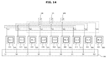
- FIG. 14 illustrates a concept of respectively connecting both ends of a wound wire respectively to a neutral point port and a driving point port.
- the 9 driving points P and 9 neutral points N should be connected to the driving point ports PP of each phase and the neutral point ports NP.
- first neutral point N1 that is the other end of the fourth coil 540
- second neutral point N2 that is the other end of the seventh coil 570
- third neutral point N3 that is the other end of the first coil 510
- fourth neutral point N4 that is the other end of the second coil 520
- fifth neutral point N5 that is the other end of the seventh coil 570
- sixth neutral point N6 that is the other end of the eighth coil 580
- seventh neutral point N7 that is the other end of the third coil 530
- eighth neutral point N8 that is the other end of the sixth coil 560
- a ninth neutral point N9 that is the other end of the ninth coil 590
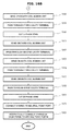
- FIG. 15 illustrates a concept of winding one wire on one coil bobbin unit group and cutting the wire.
- one wire is wound on the V-phase coil bobbin unit group in series to prepare n coils (S130), and the wire is cut at cutting points to convert the series pattern of the V-phase coil group into a parallel pattern (S140).
- n neutral points are connected to a neutral point port (S170).
- n U-phase driving points are connected to a U-phase driving point port
- n V-phase driving points are connected to a V-phase driving point port
- n W-phase driving points are connected to a W-phase driving point port.
- the wire drawn out from the second cavity terminal is wound on the seventh coil bobbin unit to prepare a seventh coil (S113), and the wire led out from the seventh coil bobbin unit is organized near a first coil bobbin unit by passing the wire through a third cavity terminal (S114).
- the prepared U-phase wire is cut at predetermined cutting points (S121).
- a wire is wound on a second coil bobbin unit to prepare a second coil (S131), and the wire led out from the second coil bobbin unit is organized near a fifth coil bobbin unit by passing the wire through the first cavity terminal (S132).
- the wire drawn out from the first cavity terminal is wound on the fifth coil bobbin unit to prepare a fifth coil (S133), and the wire led out from the fifth coil bobbin unit is organized near an eighth coil bobbin unit by passing the wire through a second cavity terminal (S134).
- a wire is wound on a third coil bobbin unit to prepare a third coil (S151), and the wire led out from the third coil bobbin unit is organized near a sixth coil bobbin unit by passing the wire through the second cavity terminal (S 152).
- the wire drawn out from the second cavity terminal is wound on the sixth coil bobbin unit to prepare a sixth coil (S153), and the wire led out from the sixth coil bobbin unit is organized near a ninth coil bobbin unit by passing the wire through the third cavity terminal (S154).
- the prepared W-phase wire is cut at predetermined cutting points (S161).
- one ends of the 9 coils are connected to form a neutral point, and the neutral point is connected to a neutral point port (S171), and the other ends of the 9 coils are connected to respectively form a driving point of each phase, and the driving points are connected to driving point ports (S181).
- a method of manufacturing a 3-phase n-slot motor 100 will be described. As illustrated in FIG. 17 , one wire is wound on coil bobbin units of the U-phase coil group in series to prepare n coils (S210), the wire led out from the U-phase coil group is wound on coil bobbin units of the V-phase coil group in series to prepare n coils (S220), and the wire led out from the V-phase coil group is wound on coil bobbin units of the W-phase coil group in series to prepare n coils (S230).
- the wire of each phase is cut at predetermined cutting points (S240).
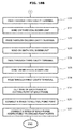
- FIG. 18 is a flowchart illustrating a process of winding one wire on three coil bobbin units of each of the three coil bobbin unit groups and cutting the wire.
- a wire is wound on a fourth coil bobbin unit to prepare a fourth coil (S211), and the wire led out from the fourth coil bobbin unit is organized near a seventh coil bobbin unit by passing the wire through a second cavity terminal (S212).
- the wire drawn out from the second cavity terminal is wound on the seventh coil bobbin unit to prepare a seventh coil (S213), and the wire led out from the seventh coil bobbin unit is organized near a first coil bobbin unit by passing the wire through a third cavity terminal (S214).
- the wire drawn out from the third cavity terminal is wound on the first coil bobbin unit to prepare a first coil (S215), and the wire led out from the first coil bobbin unit is organized near a second coil bobbin unit by passing the wire through a first cavity terminal (S216).
- a wire drawn out from the first cavity terminal is wound on the second coil bobbin unit to prepare a second coil (S221), and the wire led out from the second coil bobbin unit is organized near a fifth coil bobbin unit by passing the wire through the first cavity terminal (S222).
- the wire drawn out from the first cavity terminal is wound on the fifth coil bobbin unit to prepare a fifth coil (S223), and the wire led out from the fifth coil bobbin unit is organized near an eighth coil bobbin unit by passing the wire through a second cavity terminal (S224).
- the wire drawn out from the second cavity terminal is wound on the eighth coil bobbin unit to prepare an eighth coil (S225), and the wire led out from the eighth coil bobbin unit is organized near a third coil bobbin unit by passing the wire through a third cavity terminal (S226).
- a wire drawn out from the third cavity terminal is wound on the third coil bobbin unit to prepare a third coil (S231), and the wire led out from the third coil bobbin unit is organized near a sixth coil bobbin unit by passing the wire through the second cavity terminal (S 152).
- the wire drawn out from the second cavity terminal is wound on the sixth coil bobbin unit to prepare a sixth coil (S223), and the wire led out from the sixth coil bobbin unit is organized near a ninth coil bobbin unit by passing the wire through the third cavity terminal (S234).
- the wire drawn out from the third cavity terminal is wound on the ninth coil bobbin unit to prepare a ninth coil (S235), and the wire led out from the ninth coil bobbin unit is passed through the first cavity terminal (S236).
- one ends of the 9 coils are connected as a neutral point and connected to a neutral point port (S251), and the other ends of the 3 phase coils are connected as driving points and respectively connected to driving point ports (S261).
- wires may be efficiently organized and the working process may be simplified by converting the series pattern of the wires into a parallel pattern and locating driving points connected to the driving point port of each phase to be adjacent to each phase.
Landscapes
- Engineering & Computer Science (AREA)
- Power Engineering (AREA)
- Manufacturing & Machinery (AREA)
- Insulation, Fastening Of Motor, Generator Windings (AREA)
- Manufacture Of Motors, Generators (AREA)
- Windings For Motors And Generators (AREA)
Applications Claiming Priority (2)
| Application Number | Priority Date | Filing Date | Title |
|---|---|---|---|
| KR1020140050595A KR102233309B1 (ko) | 2014-04-28 | 2014-04-28 | 모터 및 모터의 제조방법 |
| PCT/KR2015/002929 WO2015167124A1 (fr) | 2014-04-28 | 2015-03-25 | Moteur et son procédé de fabrication |
Publications (3)
| Publication Number | Publication Date |
|---|---|
| EP3089331A1 true EP3089331A1 (fr) | 2016-11-02 |
| EP3089331A4 EP3089331A4 (fr) | 2017-08-09 |
| EP3089331B1 EP3089331B1 (fr) | 2019-12-25 |
Family
ID=54358814
Family Applications (1)
| Application Number | Title | Priority Date | Filing Date |
|---|---|---|---|
| EP15785543.8A Active EP3089331B1 (fr) | 2014-04-28 | 2015-03-25 | Moteur et son procédé de fabrication |
Country Status (5)
| Country | Link |
|---|---|
| US (1) | US10944304B2 (fr) |
| EP (1) | EP3089331B1 (fr) |
| KR (1) | KR102233309B1 (fr) |
| CN (1) | CN106256073B (fr) |
| WO (1) | WO2015167124A1 (fr) |
Cited By (1)
| Publication number | Priority date | Publication date | Assignee | Title |
|---|---|---|---|---|
| EP3879676A1 (fr) * | 2020-03-10 | 2021-09-15 | LG Electronics Inc. | Moteur de ventilateur et appareil ménager le comprenant |
Families Citing this family (8)
| Publication number | Priority date | Publication date | Assignee | Title |
|---|---|---|---|---|
| KR102233309B1 (ko) | 2014-04-28 | 2021-03-29 | 삼성전자주식회사 | 모터 및 모터의 제조방법 |
| JP7084237B2 (ja) * | 2018-07-11 | 2022-06-14 | マブチモーター株式会社 | ロータ及びモータ、並びに、ロータの結線方法 |
| CN109301950B (zh) * | 2018-11-12 | 2023-09-26 | 深圳贝格动力科技有限公司 | 一种定子绕组及盘式电机 |
| CN109742910B (zh) * | 2019-01-31 | 2023-10-20 | 重庆昆旺电子有限责任公司 | 电机软板组装设备 |
| JP2021019382A (ja) * | 2019-07-17 | 2021-02-15 | 株式会社デンソー | 回転電機 |
| KR102568303B1 (ko) * | 2020-11-02 | 2023-08-18 | 주식회사 삼현 | 소형 모터 모듈용 스테이터 구조체 |
| KR102584225B1 (ko) * | 2020-11-10 | 2023-10-05 | 주식회사 삼현 | 소형 모터 모듈용 스테이터 구조체 |
| JP2023023784A (ja) * | 2021-08-06 | 2023-02-16 | 日本電産株式会社 | 導線の引き回し構造、モータ、レゾルバ及び電子機器の製造方法 |
Family Cites Families (20)
| Publication number | Priority date | Publication date | Assignee | Title |
|---|---|---|---|---|
| US6404086B1 (en) * | 1996-09-13 | 2002-06-11 | Hitachi, Ltd. | Anisotropic magnet brushless motor having a rotor with elastic insulating support structure |
| TW380329B (en) * | 1997-04-16 | 2000-01-21 | Japan Servo | Permanent-magnet revolving electrodynamic machine with a concentrated winding stator |
| JP3623683B2 (ja) * | 1999-03-09 | 2005-02-23 | 山洋電気株式会社 | 回転電機用ステータの製造方法及び回転電機用ステータ |
| JP3613262B2 (ja) * | 2002-04-26 | 2005-01-26 | 三菱電機株式会社 | 回転電機およびその製造方法 |
| JP2005224052A (ja) | 2004-02-06 | 2005-08-18 | Fujitsu General Ltd | 電動機およびその製造方法 |
| JP4112535B2 (ja) * | 2004-07-30 | 2008-07-02 | 株式会社一宮電機 | ステータ及びブラシレスモータ |
| JP4704177B2 (ja) * | 2005-10-14 | 2011-06-15 | 株式会社小田原エンジニアリング | 3相9極のステータ及びそのステータコイル巻線方法 |
| JP2007215305A (ja) | 2006-02-08 | 2007-08-23 | Denso Corp | モータおよびその制御装置 |
| JP2007306636A (ja) | 2006-05-08 | 2007-11-22 | Kokusan Denki Co Ltd | インナーロータ型回転電機用固定子 |
| DE102007040809A1 (de) | 2007-08-29 | 2009-03-05 | Continental Automotive Gmbh | Drehstrommotor |
| US8901797B2 (en) * | 2008-01-29 | 2014-12-02 | Ford Global Technologies, Llc | Brushless motor system for a vehicle fuel pump |
| JP2010154619A (ja) | 2008-12-24 | 2010-07-08 | Aisin Aw Co Ltd | 電機子の製造方法及び電機子 |
| JP2010166643A (ja) | 2009-01-13 | 2010-07-29 | Mitsubishi Electric Corp | 密閉型圧縮機及び冷凍サイクル装置 |
| US9712028B2 (en) * | 2012-03-30 | 2017-07-18 | Amotech Co., Ltd. | Stator having three-line connection structure, BLDC motor using same, and driving method therefor |
| JP5930801B2 (ja) * | 2012-03-30 | 2016-06-08 | 日立オートモティブシステムズ株式会社 | 車載用モータ、及びそれを用いた電動パワーステアリング装置 |
| KR101383257B1 (ko) | 2012-03-30 | 2014-04-08 | 주식회사 아모텍 | 3결선 구조의 스테이터 및 이를 이용한 bldc 모터 |
| US10170954B2 (en) * | 2014-02-17 | 2019-01-01 | Hitachi Automotive Systems, Ltd. | Direct current motor |
| KR102233309B1 (ko) | 2014-04-28 | 2021-03-29 | 삼성전자주식회사 | 모터 및 모터의 제조방법 |
| JP6439622B2 (ja) * | 2015-07-31 | 2018-12-19 | 株式会社デンソー | 回転電機の固定子 |
| WO2017110419A1 (fr) * | 2015-12-25 | 2017-06-29 | 日立オートモティブシステムズエンジニアリング株式会社 | Machine électrique rotative |
-
2014
- 2014-04-28 KR KR1020140050595A patent/KR102233309B1/ko active IP Right Grant
-
2015
- 2015-03-25 US US15/112,521 patent/US10944304B2/en active Active
- 2015-03-25 CN CN201580022815.2A patent/CN106256073B/zh active Active
- 2015-03-25 WO PCT/KR2015/002929 patent/WO2015167124A1/fr active Application Filing
- 2015-03-25 EP EP15785543.8A patent/EP3089331B1/fr active Active
Cited By (2)
| Publication number | Priority date | Publication date | Assignee | Title |
|---|---|---|---|---|
| EP3879676A1 (fr) * | 2020-03-10 | 2021-09-15 | LG Electronics Inc. | Moteur de ventilateur et appareil ménager le comprenant |
| US11682954B2 (en) | 2020-03-10 | 2023-06-20 | Lg Electronics Inc. | Fan motor and home appliance including same |
Also Published As
| Publication number | Publication date |
|---|---|
| CN106256073A (zh) | 2016-12-21 |
| EP3089331A4 (fr) | 2017-08-09 |
| KR102233309B1 (ko) | 2021-03-29 |
| EP3089331B1 (fr) | 2019-12-25 |
| WO2015167124A1 (fr) | 2015-11-05 |
| KR20150124151A (ko) | 2015-11-05 |
| US10944304B2 (en) | 2021-03-09 |
| US20170126085A1 (en) | 2017-05-04 |
| CN106256073B (zh) | 2020-03-27 |
Similar Documents
| Publication | Publication Date | Title |
|---|---|---|
| EP3089331B1 (fr) | Moteur et son procédé de fabrication | |
| US11025129B2 (en) | Wire support for motor stator | |
| EP2973943B1 (fr) | Machine électrique à flux axial et ses procédés d'assemblage | |
| EP2273654A2 (fr) | Machine électrique tournante et son procédé de fabrication | |
| WO2012090295A1 (fr) | Stator et machine électrique rotative dotée dudit stator | |
| US20110156499A1 (en) | Linear synchronous motor | |
| JP2006115681A (ja) | 電気モータ | |
| CN102782987A (zh) | 具有径向安装的齿的定子 | |
| CN113574774B (zh) | 定子和电动机 | |
| CN105743258B (zh) | 定子组件、具有定子组件的马达和定子组件的制造方法 | |
| JP6248433B2 (ja) | モータ | |
| EP1372250B1 (fr) | Moteur électrique à commutation électronique | |
| EP3767799A1 (fr) | Moteur | |
| US20150115765A1 (en) | Motor and method of winding stator coil | |
| US6967554B2 (en) | Coil for a rotary electric machine | |
| US9484780B2 (en) | Segmented armature motor having a segmented coil frame having coil windings on the outer surface | |
| JP2000060074A (ja) | 整流子モータ | |
| KR20140132751A (ko) | 전기 모터 | |
| KR20110045568A (ko) | 축방향 자속형 모터 및 그 제조 방법 | |
| CN102308457B (zh) | 直流电机 | |
| KR20160087872A (ko) | 전기 모터 | |
| CN113574773A (zh) | 定子和电动机 | |
| JP2015133845A (ja) | モータ | |
| CN218040947U (zh) | 用于轴向磁通电机的定子以及轴向磁通电机 | |
| KR102469628B1 (ko) | 모터 |
Legal Events
| Date | Code | Title | Description |
|---|---|---|---|
| PUAI | Public reference made under article 153(3) epc to a published international application that has entered the european phase |
Free format text: ORIGINAL CODE: 0009012 |
|
| 17P | Request for examination filed |
Effective date: 20160729 |
|
| AK | Designated contracting states |
Kind code of ref document: A1 Designated state(s): AL AT BE BG CH CY CZ DE DK EE ES FI FR GB GR HR HU IE IS IT LI LT LU LV MC MK MT NL NO PL PT RO RS SE SI SK SM TR |
|
| AX | Request for extension of the european patent |
Extension state: BA ME |
|
| DAV | Request for validation of the european patent (deleted) | ||
| DAX | Request for extension of the european patent (deleted) | ||
| A4 | Supplementary search report drawn up and despatched |
Effective date: 20170711 |
|
| RIC1 | Information provided on ipc code assigned before grant |
Ipc: H02K 3/38 20060101ALI20170706BHEP Ipc: H02K 3/48 20060101AFI20170706BHEP |
|
| STAA | Information on the status of an ep patent application or granted ep patent |
Free format text: STATUS: EXAMINATION IS IN PROGRESS |
|
| 17Q | First examination report despatched |
Effective date: 20181120 |
|
| GRAP | Despatch of communication of intention to grant a patent |
Free format text: ORIGINAL CODE: EPIDOSNIGR1 |
|
| STAA | Information on the status of an ep patent application or granted ep patent |
Free format text: STATUS: GRANT OF PATENT IS INTENDED |
|
| INTG | Intention to grant announced |
Effective date: 20190801 |
|
| GRAS | Grant fee paid |
Free format text: ORIGINAL CODE: EPIDOSNIGR3 |
|
| GRAA | (expected) grant |
Free format text: ORIGINAL CODE: 0009210 |
|
| STAA | Information on the status of an ep patent application or granted ep patent |
Free format text: STATUS: THE PATENT HAS BEEN GRANTED |
|
| AK | Designated contracting states |
Kind code of ref document: B1 Designated state(s): AL AT BE BG CH CY CZ DE DK EE ES FI FR GB GR HR HU IE IS IT LI LT LU LV MC MK MT NL NO PL PT RO RS SE SI SK SM TR |
|
| RAP1 | Party data changed (applicant data changed or rights of an application transferred) |
Owner name: SAMSUNG ELECTRONICS CO., LTD. |
|
| REG | Reference to a national code |
Ref country code: GB Ref legal event code: FG4D |
|
| REG | Reference to a national code |
Ref country code: CH Ref legal event code: EP |
|
| REG | Reference to a national code |
Ref country code: AT Ref legal event code: REF Ref document number: 1218221 Country of ref document: AT Kind code of ref document: T Effective date: 20200115 |
|
| REG | Reference to a national code |
Ref country code: DE Ref legal event code: R096 Ref document number: 602015044347 Country of ref document: DE |
|
| REG | Reference to a national code |
Ref country code: IE Ref legal event code: FG4D |
|
| REG | Reference to a national code |
Ref country code: NL Ref legal event code: MP Effective date: 20191225 |
|
| PG25 | Lapsed in a contracting state [announced via postgrant information from national office to epo] |
Ref country code: LT Free format text: LAPSE BECAUSE OF FAILURE TO SUBMIT A TRANSLATION OF THE DESCRIPTION OR TO PAY THE FEE WITHIN THE PRESCRIBED TIME-LIMIT Effective date: 20191225 Ref country code: NO Free format text: LAPSE BECAUSE OF FAILURE TO SUBMIT A TRANSLATION OF THE DESCRIPTION OR TO PAY THE FEE WITHIN THE PRESCRIBED TIME-LIMIT Effective date: 20200325 Ref country code: GR Free format text: LAPSE BECAUSE OF FAILURE TO SUBMIT A TRANSLATION OF THE DESCRIPTION OR TO PAY THE FEE WITHIN THE PRESCRIBED TIME-LIMIT Effective date: 20200326 Ref country code: SE Free format text: LAPSE BECAUSE OF FAILURE TO SUBMIT A TRANSLATION OF THE DESCRIPTION OR TO PAY THE FEE WITHIN THE PRESCRIBED TIME-LIMIT Effective date: 20191225 Ref country code: LV Free format text: LAPSE BECAUSE OF FAILURE TO SUBMIT A TRANSLATION OF THE DESCRIPTION OR TO PAY THE FEE WITHIN THE PRESCRIBED TIME-LIMIT Effective date: 20191225 Ref country code: FI Free format text: LAPSE BECAUSE OF FAILURE TO SUBMIT A TRANSLATION OF THE DESCRIPTION OR TO PAY THE FEE WITHIN THE PRESCRIBED TIME-LIMIT Effective date: 20191225 Ref country code: BG Free format text: LAPSE BECAUSE OF FAILURE TO SUBMIT A TRANSLATION OF THE DESCRIPTION OR TO PAY THE FEE WITHIN THE PRESCRIBED TIME-LIMIT Effective date: 20200325 |
|
| REG | Reference to a national code |
Ref country code: LT Ref legal event code: MG4D |
|
| PG25 | Lapsed in a contracting state [announced via postgrant information from national office to epo] |
Ref country code: HR Free format text: LAPSE BECAUSE OF FAILURE TO SUBMIT A TRANSLATION OF THE DESCRIPTION OR TO PAY THE FEE WITHIN THE PRESCRIBED TIME-LIMIT Effective date: 20191225 Ref country code: RS Free format text: LAPSE BECAUSE OF FAILURE TO SUBMIT A TRANSLATION OF THE DESCRIPTION OR TO PAY THE FEE WITHIN THE PRESCRIBED TIME-LIMIT Effective date: 20191225 |
|
| PG25 | Lapsed in a contracting state [announced via postgrant information from national office to epo] |
Ref country code: AL Free format text: LAPSE BECAUSE OF FAILURE TO SUBMIT A TRANSLATION OF THE DESCRIPTION OR TO PAY THE FEE WITHIN THE PRESCRIBED TIME-LIMIT Effective date: 20191225 |
|
| PG25 | Lapsed in a contracting state [announced via postgrant information from national office to epo] |
Ref country code: CZ Free format text: LAPSE BECAUSE OF FAILURE TO SUBMIT A TRANSLATION OF THE DESCRIPTION OR TO PAY THE FEE WITHIN THE PRESCRIBED TIME-LIMIT Effective date: 20191225 Ref country code: PT Free format text: LAPSE BECAUSE OF FAILURE TO SUBMIT A TRANSLATION OF THE DESCRIPTION OR TO PAY THE FEE WITHIN THE PRESCRIBED TIME-LIMIT Effective date: 20200520 Ref country code: NL Free format text: LAPSE BECAUSE OF FAILURE TO SUBMIT A TRANSLATION OF THE DESCRIPTION OR TO PAY THE FEE WITHIN THE PRESCRIBED TIME-LIMIT Effective date: 20191225 Ref country code: RO Free format text: LAPSE BECAUSE OF FAILURE TO SUBMIT A TRANSLATION OF THE DESCRIPTION OR TO PAY THE FEE WITHIN THE PRESCRIBED TIME-LIMIT Effective date: 20191225 Ref country code: EE Free format text: LAPSE BECAUSE OF FAILURE TO SUBMIT A TRANSLATION OF THE DESCRIPTION OR TO PAY THE FEE WITHIN THE PRESCRIBED TIME-LIMIT Effective date: 20191225 |
|
| PG25 | Lapsed in a contracting state [announced via postgrant information from national office to epo] |
Ref country code: SM Free format text: LAPSE BECAUSE OF FAILURE TO SUBMIT A TRANSLATION OF THE DESCRIPTION OR TO PAY THE FEE WITHIN THE PRESCRIBED TIME-LIMIT Effective date: 20191225 Ref country code: SK Free format text: LAPSE BECAUSE OF FAILURE TO SUBMIT A TRANSLATION OF THE DESCRIPTION OR TO PAY THE FEE WITHIN THE PRESCRIBED TIME-LIMIT Effective date: 20191225 Ref country code: IS Free format text: LAPSE BECAUSE OF FAILURE TO SUBMIT A TRANSLATION OF THE DESCRIPTION OR TO PAY THE FEE WITHIN THE PRESCRIBED TIME-LIMIT Effective date: 20200425 |
|
| REG | Reference to a national code |
Ref country code: DE Ref legal event code: R097 Ref document number: 602015044347 Country of ref document: DE |
|
| PG25 | Lapsed in a contracting state [announced via postgrant information from national office to epo] |
Ref country code: DK Free format text: LAPSE BECAUSE OF FAILURE TO SUBMIT A TRANSLATION OF THE DESCRIPTION OR TO PAY THE FEE WITHIN THE PRESCRIBED TIME-LIMIT Effective date: 20191225 Ref country code: ES Free format text: LAPSE BECAUSE OF FAILURE TO SUBMIT A TRANSLATION OF THE DESCRIPTION OR TO PAY THE FEE WITHIN THE PRESCRIBED TIME-LIMIT Effective date: 20191225 Ref country code: MC Free format text: LAPSE BECAUSE OF FAILURE TO SUBMIT A TRANSLATION OF THE DESCRIPTION OR TO PAY THE FEE WITHIN THE PRESCRIBED TIME-LIMIT Effective date: 20191225 |
|
| PLBE | No opposition filed within time limit |
Free format text: ORIGINAL CODE: 0009261 |
|
| REG | Reference to a national code |
Ref country code: CH Ref legal event code: PL |
|
| STAA | Information on the status of an ep patent application or granted ep patent |
Free format text: STATUS: NO OPPOSITION FILED WITHIN TIME LIMIT |
|
| REG | Reference to a national code |
Ref country code: AT Ref legal event code: MK05 Ref document number: 1218221 Country of ref document: AT Kind code of ref document: T Effective date: 20191225 |
|
| PG25 | Lapsed in a contracting state [announced via postgrant information from national office to epo] |
Ref country code: SI Free format text: LAPSE BECAUSE OF FAILURE TO SUBMIT A TRANSLATION OF THE DESCRIPTION OR TO PAY THE FEE WITHIN THE PRESCRIBED TIME-LIMIT Effective date: 20191225 |
|
| 26N | No opposition filed |
Effective date: 20200928 |
|
| REG | Reference to a national code |
Ref country code: BE Ref legal event code: MM Effective date: 20200331 |
|
| PG25 | Lapsed in a contracting state [announced via postgrant information from national office to epo] |
Ref country code: LU Free format text: LAPSE BECAUSE OF NON-PAYMENT OF DUE FEES Effective date: 20200325 |
|
| PG25 | Lapsed in a contracting state [announced via postgrant information from national office to epo] |
Ref country code: CH Free format text: LAPSE BECAUSE OF NON-PAYMENT OF DUE FEES Effective date: 20200331 Ref country code: LI Free format text: LAPSE BECAUSE OF NON-PAYMENT OF DUE FEES Effective date: 20200331 Ref country code: FR Free format text: LAPSE BECAUSE OF NON-PAYMENT OF DUE FEES Effective date: 20200331 Ref country code: IE Free format text: LAPSE BECAUSE OF NON-PAYMENT OF DUE FEES Effective date: 20200325 Ref country code: AT Free format text: LAPSE BECAUSE OF FAILURE TO SUBMIT A TRANSLATION OF THE DESCRIPTION OR TO PAY THE FEE WITHIN THE PRESCRIBED TIME-LIMIT Effective date: 20191225 |
|
| PG25 | Lapsed in a contracting state [announced via postgrant information from national office to epo] |
Ref country code: PL Free format text: LAPSE BECAUSE OF FAILURE TO SUBMIT A TRANSLATION OF THE DESCRIPTION OR TO PAY THE FEE WITHIN THE PRESCRIBED TIME-LIMIT Effective date: 20191225 Ref country code: BE Free format text: LAPSE BECAUSE OF NON-PAYMENT OF DUE FEES Effective date: 20200331 |
|
| GBPC | Gb: european patent ceased through non-payment of renewal fee |
Effective date: 20200325 |
|
| PG25 | Lapsed in a contracting state [announced via postgrant information from national office to epo] |
Ref country code: GB Free format text: LAPSE BECAUSE OF NON-PAYMENT OF DUE FEES Effective date: 20200325 |
|
| PG25 | Lapsed in a contracting state [announced via postgrant information from national office to epo] |
Ref country code: TR Free format text: LAPSE BECAUSE OF FAILURE TO SUBMIT A TRANSLATION OF THE DESCRIPTION OR TO PAY THE FEE WITHIN THE PRESCRIBED TIME-LIMIT Effective date: 20191225 Ref country code: MT Free format text: LAPSE BECAUSE OF FAILURE TO SUBMIT A TRANSLATION OF THE DESCRIPTION OR TO PAY THE FEE WITHIN THE PRESCRIBED TIME-LIMIT Effective date: 20191225 Ref country code: CY Free format text: LAPSE BECAUSE OF FAILURE TO SUBMIT A TRANSLATION OF THE DESCRIPTION OR TO PAY THE FEE WITHIN THE PRESCRIBED TIME-LIMIT Effective date: 20191225 |
|
| PG25 | Lapsed in a contracting state [announced via postgrant information from national office to epo] |
Ref country code: MK Free format text: LAPSE BECAUSE OF FAILURE TO SUBMIT A TRANSLATION OF THE DESCRIPTION OR TO PAY THE FEE WITHIN THE PRESCRIBED TIME-LIMIT Effective date: 20191225 |
|
| PGFP | Annual fee paid to national office [announced via postgrant information from national office to epo] |
Ref country code: IT Payment date: 20230222 Year of fee payment: 9 |
|
| PGFP | Annual fee paid to national office [announced via postgrant information from national office to epo] |
Ref country code: DE Payment date: 20240220 Year of fee payment: 10 |