EP3087270B1 - Starter engine solenoid - Google Patents
Starter engine solenoid Download PDFInfo
- Publication number
- EP3087270B1 EP3087270B1 EP14835690.0A EP14835690A EP3087270B1 EP 3087270 B1 EP3087270 B1 EP 3087270B1 EP 14835690 A EP14835690 A EP 14835690A EP 3087270 B1 EP3087270 B1 EP 3087270B1
- Authority
- EP
- European Patent Office
- Prior art keywords
- diode
- structural body
- solenoid
- starter engine
- accommodation
- Prior art date
- Legal status (The legal status is an assumption and is not a legal conclusion. Google has not performed a legal analysis and makes no representation as to the accuracy of the status listed.)
- Active
Links
- 239000007858 starting material Substances 0.000 title claims description 39
- 230000004308 accommodation Effects 0.000 claims description 60
- 239000011810 insulating material Substances 0.000 claims description 6
- 230000000630 rising effect Effects 0.000 claims description 5
- 239000000463 material Substances 0.000 claims description 4
- 229920001971 elastomer Polymers 0.000 claims description 3
- 239000004033 plastic Substances 0.000 claims description 3
- 229920003023 plastic Polymers 0.000 claims description 3
- 229920000642 polymer Polymers 0.000 claims description 3
- 229920001296 polysiloxane Polymers 0.000 claims description 3
- 238000003825 pressing Methods 0.000 claims description 2
- 238000002788 crimping Methods 0.000 description 11
- 238000000034 method Methods 0.000 description 11
- 230000008569 process Effects 0.000 description 8
- 238000004519 manufacturing process Methods 0.000 description 6
- 238000002485 combustion reaction Methods 0.000 description 5
- 238000009434 installation Methods 0.000 description 5
- 238000003466 welding Methods 0.000 description 5
- 238000003780 insertion Methods 0.000 description 4
- 230000037431 insertion Effects 0.000 description 4
- 230000008901 benefit Effects 0.000 description 3
- 230000000295 complement effect Effects 0.000 description 2
- 230000000694 effects Effects 0.000 description 2
- 238000011900 installation process Methods 0.000 description 2
- 238000012986 modification Methods 0.000 description 2
- 230000004048 modification Effects 0.000 description 2
- 241001342895 Chorus Species 0.000 description 1
- 230000009471 action Effects 0.000 description 1
- 238000004891 communication Methods 0.000 description 1
- 238000010276 construction Methods 0.000 description 1
- 230000008878 coupling Effects 0.000 description 1
- 238000010168 coupling process Methods 0.000 description 1
- 238000005859 coupling reaction Methods 0.000 description 1
- HAORKNGNJCEJBX-UHFFFAOYSA-N cyprodinil Chemical compound N=1C(C)=CC(C2CC2)=NC=1NC1=CC=CC=C1 HAORKNGNJCEJBX-UHFFFAOYSA-N 0.000 description 1
- 238000003754 machining Methods 0.000 description 1
- 230000007246 mechanism Effects 0.000 description 1
- 230000001737 promoting effect Effects 0.000 description 1
- 239000011347 resin Substances 0.000 description 1
- 229920005989 resin Polymers 0.000 description 1
- 238000005476 soldering Methods 0.000 description 1
Images

Classifications
-
- H—ELECTRICITY
- H01—ELECTRIC ELEMENTS
- H01F—MAGNETS; INDUCTANCES; TRANSFORMERS; SELECTION OF MATERIALS FOR THEIR MAGNETIC PROPERTIES
- H01F7/00—Magnets
- H01F7/06—Electromagnets; Actuators including electromagnets
- H01F7/08—Electromagnets; Actuators including electromagnets with armatures
-
- F—MECHANICAL ENGINEERING; LIGHTING; HEATING; WEAPONS; BLASTING
- F02—COMBUSTION ENGINES; HOT-GAS OR COMBUSTION-PRODUCT ENGINE PLANTS
- F02N—STARTING OF COMBUSTION ENGINES; STARTING AIDS FOR SUCH ENGINES, NOT OTHERWISE PROVIDED FOR
- F02N15/00—Other power-operated starting apparatus; Component parts, details, or accessories, not provided for in, or of interest apart from groups F02N5/00 - F02N13/00
- F02N15/006—Assembling or mounting of starting devices
-
- F—MECHANICAL ENGINEERING; LIGHTING; HEATING; WEAPONS; BLASTING
- F02—COMBUSTION ENGINES; HOT-GAS OR COMBUSTION-PRODUCT ENGINE PLANTS
- F02N—STARTING OF COMBUSTION ENGINES; STARTING AIDS FOR SUCH ENGINES, NOT OTHERWISE PROVIDED FOR
- F02N11/00—Starting of engines by means of electric motors
- F02N11/08—Circuits or control means specially adapted for starting of engines
- F02N11/0859—Circuits or control means specially adapted for starting of engines specially adapted to the type of the starter motor or integrated into it
-
- F—MECHANICAL ENGINEERING; LIGHTING; HEATING; WEAPONS; BLASTING
- F02—COMBUSTION ENGINES; HOT-GAS OR COMBUSTION-PRODUCT ENGINE PLANTS
- F02N—STARTING OF COMBUSTION ENGINES; STARTING AIDS FOR SUCH ENGINES, NOT OTHERWISE PROVIDED FOR
- F02N15/00—Other power-operated starting apparatus; Component parts, details, or accessories, not provided for in, or of interest apart from groups F02N5/00 - F02N13/00
- F02N15/10—Safety devices not otherwise provided for
-
- F—MECHANICAL ENGINEERING; LIGHTING; HEATING; WEAPONS; BLASTING
- F02—COMBUSTION ENGINES; HOT-GAS OR COMBUSTION-PRODUCT ENGINE PLANTS
- F02N—STARTING OF COMBUSTION ENGINES; STARTING AIDS FOR SUCH ENGINES, NOT OTHERWISE PROVIDED FOR
- F02N11/00—Starting of engines by means of electric motors
-
- F—MECHANICAL ENGINEERING; LIGHTING; HEATING; WEAPONS; BLASTING
- F02—COMBUSTION ENGINES; HOT-GAS OR COMBUSTION-PRODUCT ENGINE PLANTS
- F02N—STARTING OF COMBUSTION ENGINES; STARTING AIDS FOR SUCH ENGINES, NOT OTHERWISE PROVIDED FOR
- F02N11/00—Starting of engines by means of electric motors
- F02N11/08—Circuits or control means specially adapted for starting of engines
- F02N11/0862—Circuits or control means specially adapted for starting of engines characterised by the electrical power supply means, e.g. battery
-
- F—MECHANICAL ENGINEERING; LIGHTING; HEATING; WEAPONS; BLASTING
- F02—COMBUSTION ENGINES; HOT-GAS OR COMBUSTION-PRODUCT ENGINE PLANTS
- F02N—STARTING OF COMBUSTION ENGINES; STARTING AIDS FOR SUCH ENGINES, NOT OTHERWISE PROVIDED FOR
- F02N11/00—Starting of engines by means of electric motors
- F02N11/10—Safety devices
-
- F—MECHANICAL ENGINEERING; LIGHTING; HEATING; WEAPONS; BLASTING
- F02—COMBUSTION ENGINES; HOT-GAS OR COMBUSTION-PRODUCT ENGINE PLANTS
- F02N—STARTING OF COMBUSTION ENGINES; STARTING AIDS FOR SUCH ENGINES, NOT OTHERWISE PROVIDED FOR
- F02N15/00—Other power-operated starting apparatus; Component parts, details, or accessories, not provided for in, or of interest apart from groups F02N5/00 - F02N13/00
- F02N15/02—Gearing between starting-engines and started engines; Engagement or disengagement thereof
- F02N15/04—Gearing between starting-engines and started engines; Engagement or disengagement thereof the gearing including disengaging toothed gears
- F02N15/06—Gearing between starting-engines and started engines; Engagement or disengagement thereof the gearing including disengaging toothed gears the toothed gears being moved by axial displacement
- F02N15/067—Gearing between starting-engines and started engines; Engagement or disengagement thereof the gearing including disengaging toothed gears the toothed gears being moved by axial displacement the starter comprising an electro-magnetically actuated lever
-
- F—MECHANICAL ENGINEERING; LIGHTING; HEATING; WEAPONS; BLASTING
- F02—COMBUSTION ENGINES; HOT-GAS OR COMBUSTION-PRODUCT ENGINE PLANTS
- F02N—STARTING OF COMBUSTION ENGINES; STARTING AIDS FOR SUCH ENGINES, NOT OTHERWISE PROVIDED FOR
- F02N11/00—Starting of engines by means of electric motors
- F02N11/08—Circuits or control means specially adapted for starting of engines
- F02N2011/0881—Components of the circuit not provided for by previous groups
Definitions
- the present invention relates to a diode accommodation core, particularly developed for use in solenoid of starter engines used in automotive vehicles. More preferably, the diode accommodation core, object of the present invention, comprises technical, constructive and functional aspects totally innovative and that are able to get a simple, practical, and highly e solution regarding the installation and accommodation of the diodes in the solenoids without thereby affect the structural configuration of the diodes or the structures of starter engines.
- starter engines also called starters
- starters are formed by a structure comprised basically of a cooperating solenoid with an actuating lever which in turn moves the sprocket or freewheel to connect to the crankshaft of the combustion engine.
- the actuation of these mechanisms occurs through the power supply from the moment the automotive vehicle's driver rotates the key, triggers the start button on the vehicle dashboard or the vehicle's ECU activates the actuation.
- the solenoid receives an electrical signal through the engine driving terminal thereof, which is also called “borne #50" in order to trigger the coils of said solenoid and, thus, generate a magnetic field that pulls the solenoid armature, dragging the driving lever of the starter engine.
- said actuating lever pushes the sprocket or freewheel to connect in the crankshaft gear and at the same time, the solenoid closes the electrical contact of the main circuit and starts to energize the coil and armature of the starter engine, producing a magnetic field and consequently the engine rotational motion with enough torque and speed so that the crankshaft can drive the combustion engine.
- Another solution available in the prior art comprises a combination of welding and locking by crimping the diode terminals with the solenoid structure. More specifically, this way of inserting and installing said diode consists of crimping one of the diode terminals with the male bracket of borne #50, and the other terminal is welded in the magnetic core of the solenoid. It is noted that, although functional until the present days, this solution still shows a bit complicated and can be improved and / or optimized, in particular as to the manufacturing process to ensure proper positioning of the respective electrical contacts.
- the diode accommodation core object of the present invention is yet intended to also eliminate the need for processes that lead to high manufacturing costs, for example crimping, machining, welding, or other similar manufacturing processes, which ultimately compromise the production lines and the solenoid assembly to starter engines.
- one of the main objectives of the present invention is to propose a diode accommodation core, especially for solenoids of starter engines, consisting of technical aspects developed to facilitate the manufacturing and assembly process of the solenoids, but mainly to ensure the positioning of the terminals by conducting electrical connection by pressure, without requiring adjustments in the geometric structure of the solenoids currently available on the market, or the obligatory use of welding and / or assembly additional processes.
- the present invention relates to a starter engine solenoid according to claim 1, which comprises a core for diode accommodation, as defined in claim 1, being comprised of a structural body having an opening where the body of the diode can be accommodated, and also has two contact sides which are opposite to each other, and each of them is provided with accommodation guide of the respective terminals of the diode, which has a surface portion in which at least one of said terminals is supported and at least partially exposed in relation to the surface of the corresponding contact side of the structural body, so as to promote the electrical contact with at least one adjacent component by pressure.
- the object of the present invention comprises a terminal supported and at least partially exposed to the surface of the corresponding contact side of the structural chorus, while the other terminal is crimped to the surface of the corresponding contact side of the structural body, or connected to the same by interference or other appropriate means; alternatively both terminals may remain supported and at least partially exposed regarding the surface of the corresponding contact side of the structural body.
- each of the accommodation guides extends from said opening and they are formed by an upward portion which is inclined toward the surface of the respective contact side, and by said surface portion.
- the diode accommodation core comprises accommodating tabs extending from said opening, and which are formed only by a surface portion arranged on the surface of the corresponding contact side of the structural body.
- said structural body of the diode accommodation core comprises a tablet shape.
- the opening provided in the structural body of the diode accommodation core according to the present invention has slots for the passage of the diode contact terminals, said slots being in communication with said accommodation guide arranged in each contact side of the structural body.
- said structural body of the diode accommodation core is manufactured in a flexible and insulating material. More preferably, it can be manufactured in a material selected from rubber, silicone, plastics and other insulating polymers. In particular, attention is drawn to the fact that at least the surface of the contact sides of the structural body must be covered with an insulating material.
- said structural body may comprise at least one locking portion whose purpose is to promote fitting into respective openings or slots already provided in the solenoid cover. More advantageously, with regard to fixing and adhesion, said locking portions are provided with ribs.
- the surface portions of the accommodating guides of the structural body comprise a channel profile to ensure proper positioning of the diode terminals.
- said structural body of the diode accommodation core according to the present invention comprises a shape corresponding to the screw head shape, more preferably, comprises an hexagonal shape.
- said opening may be positioned in the center of the structural body, or optionally in an asymmetric or decentralized manner.
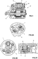
- the diode accommodation core object of the present invention is preferably applied to starter engines (M), which are made of a structure comprising essentially a solenoid (S) which cooperates with a driving lever (A) which, in turn, moves the sprocket or freewheel (R) for connection to the combustion engine.
- S solenoid
- A driving lever
- R freewheel
- said solenoid (S) comprises a cover (T) where the bornes of electrical contact are positioned, including borne #50 (B) that is fixed with the body of the cover (T) through screw (P).
- said cover (T) is fitted with the solenoid body (S) in order to press the magnetic core (N), forming between the screw head (P) and said magnetic core (N) a space (E) which is currently totally free of any material.
- Figure 2C shows more clearly that space (E) between the screw head (P) and the surface of the magnetic core (N), the diode accommodation core object of the present invention is preferably inserted and positioned in this space (E).
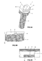
- the diode accommodation core comprises a structural body 1, preferably in tablet form, provided with opening 2 for accommodating the body 4 of the diode (D) and two contact sides 3a and 3b opposing each other, each provided with accommodation guide 5', 5" of the respective terminal 6', 6" of diode (D).
- each accommodation guide 5', 5" extends from said opening 2, and can be formed by an rising portion 7, which is inclined toward the surface of the respective contact side 3a or 3b, and a surface portion 8 in which said terminal 6', 6" is supported and at least partially exposed regarding the surface of the corresponding contact side 3a or 3b of the structural body 1.
- This configuration of the accommodation guides 5' 5" is preferred in the case of the diode (D) be horizontally accommodated in the opening 2, i.e. parallel to said contact sides 3a and 3b in order to promote electrical contact with at least one adjacent component by pressure, and therefore, without requiring the welding of components. Note that such a construction discloses a single part capable of promoting pressure connection, significantly in a more simple, practical and efficient manner than that achieved with the use of similar known ones.
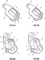
- FIGS 5A, 5B and 5C show in more detail the configuration and arrangement of said diode (D) properly embedded and accommodated in the diode accommodation core object of the present invention. More particularly, it can be seen that body 4 of the diode (D) is accommodated in opening 2 of structural body 1, and the respective contact terminals 6', 6" are folded and rested on respective accommodation guides 5', 5" of each contact side 3a and 3b of structural body 1. As can be seen, by this arrangement it is possile to ensure that said contact terminals 6', 6" remain separated and primarily isolated from one another, each contact terminal 6', 6" is positioned in one of said contact sides 3a, 3b of structural body 1.
- the contact terminal 6" is positioned on the accommodation guide 5" provided in said side 3b of the structural body 1, therewith, when the diode is allocated in the accommodation core, and side 3b positioned adjacent / on the head of screw (P), it is ensured that there will be contact between the head of screw (P) and diode (D) due to the terminal portion (6") be accommodated in the surface portion (8).
- terminal contact 6' is positioned on accommodation guide 5' provided in side 3a of structural body 1 so that, when the diode is allocated in the accomodation core, and side 3a positioned adjacent to magnetic core (N), it can ensure contact between magnetic core (N) and diode (D) due to terminal portion (6') be accommodated in surface portion (8) of contact side 3a.
- diode (D) With borne #50 and said electrical ground reference, in this case magnetic core (N), without the need for any soldering or crimping process.
- diode accomodation core more specifically structural body 1, that is comprised by opening 2 for receiving body 4 of diode (D), wherein said opening 2 has slots 9 for the passage of contact terminals 6', 6" of the diode (D), to enable folding and support of these terminals on accomodation guides 5', 5", particularly, positioning such terminals 6', 6' on rising portions 7 and, in sequence, on surface portions 8.
- said structural body 1 of the diode accommodation core is manufactured in a flexible and insulating material, and which is mainly susceptible to partial deshaping when subjected to pressure when coupling the cover (T) in the body of the solenoid (S).
- this material may be selected from rubber, silicone, plastics and other insulating polymers. More particularly, it should be clear that at least the surface of the contact sides 3a and 3b should be coated or consists of an insulating material.
- the structural body 1of the diode accommodating core according to the present invention may also comprise a locking portion 10 whose purpose is to penetrate and fit into openings or grooves provided in the cover (T) of the solenoid (S).
- this locking portion 10 can comprise different arrangements, since it should correspond to the formed and geometrical characteristics of cover (T).
- this locking portion 10 can comprise ribs 11 which enhance the flexibility, but improve the adhesion with the surface of the cover (T).
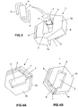
- Figures 7A, 7B, 8A, 8B , 9, 10A, 10B, 11A, 11B show in more detail the characteristics of the diode accommodation core, according to a possible embodiment of the present invention, in which case the structural body 1 comprises two locking portions 10, one smooth and the other with a series of ribs 11 to ensure the perfect fit and keep the same with the cover. It is noted that the geometrical arrangement of this embodiment is designed to meet the shape and configuration of cover (T) of solenoid (S), in which there is provision for a hole and space around the head of screw (P) of borne #50 (B).
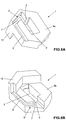
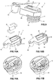
- Figures 12, 13A and 13B show another constructive embodiment of structural body 1 of the diode accommodation core according to the present invention. More particularly, in this case, it appears that there is only one locking portion 10, which is provided with a series of ribs 11 to promote proper adhesion of structural body 1 with cover (T). Further, it is noted that said cap (T) comprises a region whose geometry corresponds to locking portion 10, allowing the frame body 1 with the diode thereof (D) to be embedded in cover (T) without occupying or disrupting the operation of other components of solenoid (S).
- structural body 1 and the possible locking portions 10 thereof are designed to meet the needs and settings of each solenoid model, and more particularly to each model of cover (T) of solenoids (S).
- said surface portions 8 of accommodation guides 5', 5" may comprise a channel profile, in order to ensure the positioning of contact terminals 6', 6" of diode (D), thereby avoiding any risk of diode (D) to move and provide eventual contact failures.
- said structural body 1 comprises a hexagonal shape, since the vast majority of the solenoid models known in the current market has a borne #50 fixed by a standard screw of hexagonal head type - M6, and thus it is possible to accommodate said core in space (E) generated between screw (P) and magnetic core (C) of solenoid (S). Therefore, the shape of structural body 1 depends on the solution used in the cover of solenoid (S) which provides space (E) between the connection of borne #50 and magnetic core (N), not being necessarily hexagonal.
- the diode accommodation core is able to promote a series of advantages and technical, practical and functional benefits, eliminating process steps which are complex, expensive and difficult to perform.
- terminals 6', 6" of diode (D) are separated and insulated from each other without providing any risk of contact between them and hence it is eliminated eventual risk of failure in the operation of the diode and, as a result, one can reduce the problems and inconveniences generated by the electrical pulses generated by the energizing and de-energizing the solenoid coils.
- the diode accommodation core object of the present invention can achieve as practical results the proper support of diode (D), and at the same time, ensures that the terminals of said diode (D) are pressed against the contact of borne #50 and the electrical ground reference, more preferably, through contact with the head of screw (P) and magnetic core (N) of solenoid (S).
Landscapes
- Engineering & Computer Science (AREA)
- Chemical & Material Sciences (AREA)
- Combustion & Propulsion (AREA)
- Mechanical Engineering (AREA)
- General Engineering & Computer Science (AREA)
- Physics & Mathematics (AREA)
- Electromagnetism (AREA)
- Power Engineering (AREA)
- Electromagnets (AREA)
Applications Claiming Priority (3)
| Application Number | Priority Date | Filing Date | Title |
|---|---|---|---|
| BR102013033677A BR102013033677A2 (pt) | 2013-12-27 | 2013-12-27 | núcleo de acomodação de diodo |
| BR102014030289-1A BR102014030289B1 (pt) | 2013-12-27 | 2014-12-03 | Solenoide de motores de arranque |
| PCT/BR2014/000454 WO2015095944A1 (en) | 2013-12-27 | 2014-12-26 | Diode accomodation core |
Publications (2)
| Publication Number | Publication Date |
|---|---|
| EP3087270A1 EP3087270A1 (en) | 2016-11-02 |
| EP3087270B1 true EP3087270B1 (en) | 2021-08-11 |
Family
ID=52468856
Family Applications (1)
| Application Number | Title | Priority Date | Filing Date |
|---|---|---|---|
| EP14835690.0A Active EP3087270B1 (en) | 2013-12-27 | 2014-12-26 | Starter engine solenoid |
Country Status (4)
| Country | Link |
|---|---|
| US (1) | US9875836B2 (ja) |
| EP (1) | EP3087270B1 (ja) |
| JP (1) | JP6674379B2 (ja) |
| WO (1) | WO2015095944A1 (ja) |
Families Citing this family (1)
| Publication number | Priority date | Publication date | Assignee | Title |
|---|---|---|---|---|
| WO2017147666A1 (en) * | 2016-02-29 | 2017-09-08 | Robert Bosch Motores De Partida E Alternadores Ltda. | Housing assembly for voltage suppressor diode and manufacturing and assembling method thereof |
Family Cites Families (21)
| Publication number | Priority date | Publication date | Assignee | Title |
|---|---|---|---|---|
| JPS5263533A (en) * | 1975-11-20 | 1977-05-26 | Nissan Motor Co Ltd | Start-up device for diesel engine |
| US4169450A (en) * | 1976-12-22 | 1979-10-02 | Toyota Jidosha Kogyo Kabushiki Kaisha | Internal combustion engine for an automobile provided with an air-conditioner |
| US4432446A (en) * | 1980-06-28 | 1984-02-21 | Nippondenso Co., Ltd. | Electromagnetic coupling apparatus |
| EP0808420B1 (de) | 1995-02-03 | 1999-04-07 | Robert Bosch Gmbh | Startvorrichtung zum starten einer brennkraftmaschine |
| US5927240A (en) * | 1995-04-07 | 1999-07-27 | Maxon; Eric A. | Housing shared by vehicle component and disabling switch and decoder |
| JP3069044B2 (ja) * | 1996-05-07 | 2000-07-24 | サンデン株式会社 | 電磁連結装置 |
| US6941779B2 (en) * | 2002-07-30 | 2005-09-13 | Kabushiki Kaisha Honda Lock | Steerage locking system for vehicle |
| US6752110B2 (en) * | 2002-09-20 | 2004-06-22 | Briggs & Stratton Corporation | Electromechanical choke system for an internal combustion engine |
| US8820286B2 (en) * | 2003-08-28 | 2014-09-02 | Mainstream Engineering Corporation | Lightweight portable electric generator with integrated starter/alternator |
| JP2008166649A (ja) | 2007-01-05 | 2008-07-17 | Diamond Electric Mfg Co Ltd | 内燃機関用点火コイル |
| JP2008196373A (ja) | 2007-02-13 | 2008-08-28 | Mitsuba Corp | スタータ |
| JP4780233B2 (ja) * | 2009-05-11 | 2011-09-28 | 株式会社デンソー | エンジン始動装置 |
| JP2012094412A (ja) | 2010-10-28 | 2012-05-17 | Denso Corp | 電磁スイッチ |
| EP2538068B1 (en) * | 2011-06-22 | 2017-11-08 | Volvo Car Corporation | Method and arrangement for improving the performance of an electrical system of a vehicle |
| JP5862091B2 (ja) * | 2011-07-27 | 2016-02-16 | 株式会社デンソー | スタータ |
| US20130062891A1 (en) * | 2011-09-08 | 2013-03-14 | Enerpro, Inc. | Engine cranking motor soft-start system and method |
| US8733072B2 (en) * | 2011-11-04 | 2014-05-27 | Briggs & Stratton Corporation | Starter system for an engine |
| US9127658B2 (en) * | 2011-11-04 | 2015-09-08 | Briggs & Stratton Corporation | Internal combustion engine including starting system powered by lithium-ion battery |
| US9528487B2 (en) * | 2011-11-17 | 2016-12-27 | Ford Global Technologies, Llc | Starter motor control with pre-spin |
| DE112013005461T5 (de) * | 2012-11-14 | 2015-09-03 | Hitachi Koki Co., Ltd. | Motorbetriebenes Arbeitsgerät |
| US9429107B2 (en) * | 2013-02-22 | 2016-08-30 | Briggs & Stratton Corporation | Solenoid autochoke for an engine |
-
2014
- 2014-12-26 JP JP2016543175A patent/JP6674379B2/ja active Active
- 2014-12-26 US US15/108,049 patent/US9875836B2/en active Active
- 2014-12-26 WO PCT/BR2014/000454 patent/WO2015095944A1/en active Application Filing
- 2014-12-26 EP EP14835690.0A patent/EP3087270B1/en active Active
Also Published As
| Publication number | Publication date |
|---|---|
| EP3087270A1 (en) | 2016-11-02 |
| JP2017503955A (ja) | 2017-02-02 |
| WO2015095944A1 (en) | 2015-07-02 |
| US20160329142A1 (en) | 2016-11-10 |
| JP6674379B2 (ja) | 2020-04-01 |
| US9875836B2 (en) | 2018-01-23 |
Similar Documents
| Publication | Publication Date | Title |
|---|---|---|
| CN108886294B (zh) | 电机和用于制造电机的方法 | |
| JP4139451B2 (ja) | 自動車のスタータ用コンタクタ | |
| CN107112839B (zh) | 用于电机的定子和用于制造这样的定子的方法 | |
| JP5043201B2 (ja) | 電気機械用ブラシユニット、そのためのスプリングおよびシールの配置、および、それらの製造方法 | |
| CN105765829B (zh) | 用于电子整流式直流电动机的定子 | |
| TWI605648B (zh) | 汽車用具插頭殼體的控制裝置 | |
| CN101354002B (zh) | 用于起动内燃机的双轴型起动机 | |
| US7733201B2 (en) | Starter including electromagnetic switch with protective cover for protecting terminals | |
| CN107275036A (zh) | 电磁铁用导线的密封结构 | |
| EP3087270B1 (en) | Starter engine solenoid | |
| CN107546898B (zh) | 定子的连接装置、包含连接装置的电机和制造电机的方法 | |
| JP2007258105A (ja) | 電気接続構造 | |
| JP2009032591A (ja) | 電磁継電器 | |
| KR101281383B1 (ko) | 시동기 접촉기 | |
| JP6838711B2 (ja) | 2つの回路体へのワイヤハーネスの接続構造 | |
| JP5199615B2 (ja) | 電磁継電器 | |
| CN103794952A (zh) | 机动车辆领域中用于传送高压电流的连接装置 | |
| JP5080866B2 (ja) | 電磁継電器 | |
| WO2014024974A1 (ja) | 回転電機 | |
| WO2017147666A1 (en) | Housing assembly for voltage suppressor diode and manufacturing and assembling method thereof | |
| JP6176345B2 (ja) | 電磁クラッチの製造方法 | |
| KR101877046B1 (ko) | 스타트모터용 마그네트 스위치 | |
| JP5138984B2 (ja) | 電磁継電器 | |
| JP2010020959A (ja) | 電磁スイッチ | |
| JP5080873B2 (ja) | 電磁継電器 |
Legal Events
| Date | Code | Title | Description |
|---|---|---|---|
| PUAI | Public reference made under article 153(3) epc to a published international application that has entered the european phase |
Free format text: ORIGINAL CODE: 0009012 |
|
| STAA | Information on the status of an ep patent application or granted ep patent |
Free format text: STATUS: REQUEST FOR EXAMINATION WAS MADE |
|
| 17P | Request for examination filed |
Effective date: 20160713 |
|
| AK | Designated contracting states |
Kind code of ref document: A1 Designated state(s): AL AT BE BG CH CY CZ DE DK EE ES FI FR GB GR HR HU IE IS IT LI LT LU LV MC MK MT NL NO PL PT RO RS SE SI SK SM TR |
|
| AX | Request for extension of the european patent |
Extension state: BA ME |
|
| RAP1 | Party data changed (applicant data changed or rights of an application transferred) |
Owner name: ROBERT BOSCH MOTORES DE PARTIDA E ALTERNADORES LTD |
|
| DAX | Request for extension of the european patent (deleted) | ||
| RIC1 | Information provided on ipc code assigned before grant |
Ipc: F02N 15/06 20060101ALN20210114BHEP Ipc: F02N 15/00 20060101AFI20210114BHEP Ipc: F02N 15/10 20060101ALI20210114BHEP Ipc: F02N 11/10 20060101ALN20210114BHEP Ipc: F02N 11/08 20060101ALN20210114BHEP Ipc: F02N 15/02 20060101ALN20210114BHEP |
|
| RIC1 | Information provided on ipc code assigned before grant |
Ipc: F02N 11/10 20060101ALN20210122BHEP Ipc: F02N 15/00 20060101AFI20210122BHEP Ipc: F02N 15/10 20060101ALI20210122BHEP Ipc: F02N 15/06 20060101ALN20210122BHEP Ipc: F02N 15/02 20060101ALN20210122BHEP Ipc: F02N 11/08 20060101ALN20210122BHEP |
|
| GRAP | Despatch of communication of intention to grant a patent |
Free format text: ORIGINAL CODE: EPIDOSNIGR1 |
|
| STAA | Information on the status of an ep patent application or granted ep patent |
Free format text: STATUS: GRANT OF PATENT IS INTENDED |
|
| RIC1 | Information provided on ipc code assigned before grant |
Ipc: F02N 15/00 20060101AFI20210225BHEP Ipc: F02N 11/10 20060101ALN20210225BHEP Ipc: F02N 15/02 20060101ALN20210225BHEP Ipc: F02N 15/06 20060101ALN20210225BHEP Ipc: F02N 11/08 20060101ALN20210225BHEP Ipc: F02N 15/10 20060101ALI20210225BHEP |
|
| INTG | Intention to grant announced |
Effective date: 20210311 |
|
| GRAS | Grant fee paid |
Free format text: ORIGINAL CODE: EPIDOSNIGR3 |
|
| GRAA | (expected) grant |
Free format text: ORIGINAL CODE: 0009210 |
|
| STAA | Information on the status of an ep patent application or granted ep patent |
Free format text: STATUS: THE PATENT HAS BEEN GRANTED |
|
| AK | Designated contracting states |
Kind code of ref document: B1 Designated state(s): AL AT BE BG CH CY CZ DE DK EE ES FI FR GB GR HR HU IE IS IT LI LT LU LV MC MK MT NL NO PL PT RO RS SE SI SK SM TR |
|
| REG | Reference to a national code |
Ref country code: CH Ref legal event code: EP |
|
| REG | Reference to a national code |
Ref country code: DE Ref legal event code: R096 Ref document number: 602014079412 Country of ref document: DE |
|
| REG | Reference to a national code |
Ref country code: IE Ref legal event code: FG4D Ref country code: AT Ref legal event code: REF Ref document number: 1419628 Country of ref document: AT Kind code of ref document: T Effective date: 20210915 |
|
| REG | Reference to a national code |
Ref country code: LT Ref legal event code: MG9D |
|
| REG | Reference to a national code |
Ref country code: NL Ref legal event code: MP Effective date: 20210811 |
|
| REG | Reference to a national code |
Ref country code: AT Ref legal event code: MK05 Ref document number: 1419628 Country of ref document: AT Kind code of ref document: T Effective date: 20210811 |
|
| PG25 | Lapsed in a contracting state [announced via postgrant information from national office to epo] |
Ref country code: SE Free format text: LAPSE BECAUSE OF FAILURE TO SUBMIT A TRANSLATION OF THE DESCRIPTION OR TO PAY THE FEE WITHIN THE PRESCRIBED TIME-LIMIT Effective date: 20210811 Ref country code: RS Free format text: LAPSE BECAUSE OF FAILURE TO SUBMIT A TRANSLATION OF THE DESCRIPTION OR TO PAY THE FEE WITHIN THE PRESCRIBED TIME-LIMIT Effective date: 20210811 Ref country code: HR Free format text: LAPSE BECAUSE OF FAILURE TO SUBMIT A TRANSLATION OF THE DESCRIPTION OR TO PAY THE FEE WITHIN THE PRESCRIBED TIME-LIMIT Effective date: 20210811 Ref country code: LT Free format text: LAPSE BECAUSE OF FAILURE TO SUBMIT A TRANSLATION OF THE DESCRIPTION OR TO PAY THE FEE WITHIN THE PRESCRIBED TIME-LIMIT Effective date: 20210811 Ref country code: BG Free format text: LAPSE BECAUSE OF FAILURE TO SUBMIT A TRANSLATION OF THE DESCRIPTION OR TO PAY THE FEE WITHIN THE PRESCRIBED TIME-LIMIT Effective date: 20211111 Ref country code: AT Free format text: LAPSE BECAUSE OF FAILURE TO SUBMIT A TRANSLATION OF THE DESCRIPTION OR TO PAY THE FEE WITHIN THE PRESCRIBED TIME-LIMIT Effective date: 20210811 Ref country code: NO Free format text: LAPSE BECAUSE OF FAILURE TO SUBMIT A TRANSLATION OF THE DESCRIPTION OR TO PAY THE FEE WITHIN THE PRESCRIBED TIME-LIMIT Effective date: 20211111 Ref country code: PT Free format text: LAPSE BECAUSE OF FAILURE TO SUBMIT A TRANSLATION OF THE DESCRIPTION OR TO PAY THE FEE WITHIN THE PRESCRIBED TIME-LIMIT Effective date: 20211213 Ref country code: ES Free format text: LAPSE BECAUSE OF FAILURE TO SUBMIT A TRANSLATION OF THE DESCRIPTION OR TO PAY THE FEE WITHIN THE PRESCRIBED TIME-LIMIT Effective date: 20210811 Ref country code: FI Free format text: LAPSE BECAUSE OF FAILURE TO SUBMIT A TRANSLATION OF THE DESCRIPTION OR TO PAY THE FEE WITHIN THE PRESCRIBED TIME-LIMIT Effective date: 20210811 |
|
| PG25 | Lapsed in a contracting state [announced via postgrant information from national office to epo] |
Ref country code: PL Free format text: LAPSE BECAUSE OF FAILURE TO SUBMIT A TRANSLATION OF THE DESCRIPTION OR TO PAY THE FEE WITHIN THE PRESCRIBED TIME-LIMIT Effective date: 20210811 Ref country code: LV Free format text: LAPSE BECAUSE OF FAILURE TO SUBMIT A TRANSLATION OF THE DESCRIPTION OR TO PAY THE FEE WITHIN THE PRESCRIBED TIME-LIMIT Effective date: 20210811 |
|
| PG25 | Lapsed in a contracting state [announced via postgrant information from national office to epo] |
Ref country code: NL Free format text: LAPSE BECAUSE OF FAILURE TO SUBMIT A TRANSLATION OF THE DESCRIPTION OR TO PAY THE FEE WITHIN THE PRESCRIBED TIME-LIMIT Effective date: 20210811 |
|
| PG25 | Lapsed in a contracting state [announced via postgrant information from national office to epo] |
Ref country code: DK Free format text: LAPSE BECAUSE OF FAILURE TO SUBMIT A TRANSLATION OF THE DESCRIPTION OR TO PAY THE FEE WITHIN THE PRESCRIBED TIME-LIMIT Effective date: 20210811 |
|
| REG | Reference to a national code |
Ref country code: DE Ref legal event code: R097 Ref document number: 602014079412 Country of ref document: DE |
|
| PG25 | Lapsed in a contracting state [announced via postgrant information from national office to epo] |
Ref country code: SM Free format text: LAPSE BECAUSE OF FAILURE TO SUBMIT A TRANSLATION OF THE DESCRIPTION OR TO PAY THE FEE WITHIN THE PRESCRIBED TIME-LIMIT Effective date: 20210811 Ref country code: SK Free format text: LAPSE BECAUSE OF FAILURE TO SUBMIT A TRANSLATION OF THE DESCRIPTION OR TO PAY THE FEE WITHIN THE PRESCRIBED TIME-LIMIT Effective date: 20210811 Ref country code: RO Free format text: LAPSE BECAUSE OF FAILURE TO SUBMIT A TRANSLATION OF THE DESCRIPTION OR TO PAY THE FEE WITHIN THE PRESCRIBED TIME-LIMIT Effective date: 20210811 Ref country code: EE Free format text: LAPSE BECAUSE OF FAILURE TO SUBMIT A TRANSLATION OF THE DESCRIPTION OR TO PAY THE FEE WITHIN THE PRESCRIBED TIME-LIMIT Effective date: 20210811 Ref country code: CZ Free format text: LAPSE BECAUSE OF FAILURE TO SUBMIT A TRANSLATION OF THE DESCRIPTION OR TO PAY THE FEE WITHIN THE PRESCRIBED TIME-LIMIT Effective date: 20210811 Ref country code: AL Free format text: LAPSE BECAUSE OF FAILURE TO SUBMIT A TRANSLATION OF THE DESCRIPTION OR TO PAY THE FEE WITHIN THE PRESCRIBED TIME-LIMIT Effective date: 20210811 |
|
| PLBE | No opposition filed within time limit |
Free format text: ORIGINAL CODE: 0009261 |
|
| STAA | Information on the status of an ep patent application or granted ep patent |
Free format text: STATUS: NO OPPOSITION FILED WITHIN TIME LIMIT |
|
| 26N | No opposition filed |
Effective date: 20220512 |
|
| PG25 | Lapsed in a contracting state [announced via postgrant information from national office to epo] |
Ref country code: MC Free format text: LAPSE BECAUSE OF FAILURE TO SUBMIT A TRANSLATION OF THE DESCRIPTION OR TO PAY THE FEE WITHIN THE PRESCRIBED TIME-LIMIT Effective date: 20210811 |
|
| REG | Reference to a national code |
Ref country code: CH Ref legal event code: PL |
|
| PG25 | Lapsed in a contracting state [announced via postgrant information from national office to epo] |
Ref country code: SI Free format text: LAPSE BECAUSE OF FAILURE TO SUBMIT A TRANSLATION OF THE DESCRIPTION OR TO PAY THE FEE WITHIN THE PRESCRIBED TIME-LIMIT Effective date: 20210811 |
|
| REG | Reference to a national code |
Ref country code: BE Ref legal event code: MM Effective date: 20211231 |
|
| PG25 | Lapsed in a contracting state [announced via postgrant information from national office to epo] |
Ref country code: LU Free format text: LAPSE BECAUSE OF NON-PAYMENT OF DUE FEES Effective date: 20211226 Ref country code: IE Free format text: LAPSE BECAUSE OF NON-PAYMENT OF DUE FEES Effective date: 20211226 |
|
| PG25 | Lapsed in a contracting state [announced via postgrant information from national office to epo] |
Ref country code: BE Free format text: LAPSE BECAUSE OF NON-PAYMENT OF DUE FEES Effective date: 20211231 |
|
| PG25 | Lapsed in a contracting state [announced via postgrant information from national office to epo] |
Ref country code: LI Free format text: LAPSE BECAUSE OF NON-PAYMENT OF DUE FEES Effective date: 20211231 Ref country code: CH Free format text: LAPSE BECAUSE OF NON-PAYMENT OF DUE FEES Effective date: 20211231 |
|
| PG25 | Lapsed in a contracting state [announced via postgrant information from national office to epo] |
Ref country code: HU Free format text: LAPSE BECAUSE OF FAILURE TO SUBMIT A TRANSLATION OF THE DESCRIPTION OR TO PAY THE FEE WITHIN THE PRESCRIBED TIME-LIMIT; INVALID AB INITIO Effective date: 20141226 |
|
| PG25 | Lapsed in a contracting state [announced via postgrant information from national office to epo] |
Ref country code: CY Free format text: LAPSE BECAUSE OF FAILURE TO SUBMIT A TRANSLATION OF THE DESCRIPTION OR TO PAY THE FEE WITHIN THE PRESCRIBED TIME-LIMIT Effective date: 20210811 |
|
| PG25 | Lapsed in a contracting state [announced via postgrant information from national office to epo] |
Ref country code: GR Free format text: LAPSE BECAUSE OF FAILURE TO SUBMIT A TRANSLATION OF THE DESCRIPTION OR TO PAY THE FEE WITHIN THE PRESCRIBED TIME-LIMIT Effective date: 20210811 |
|
| PGFP | Annual fee paid to national office [announced via postgrant information from national office to epo] |
Ref country code: GB Payment date: 20231220 Year of fee payment: 10 |
|
| PGFP | Annual fee paid to national office [announced via postgrant information from national office to epo] |
Ref country code: IT Payment date: 20230926 Year of fee payment: 10 Ref country code: FR Payment date: 20231221 Year of fee payment: 10 Ref country code: DE Payment date: 20231214 Year of fee payment: 10 |
|
| PG25 | Lapsed in a contracting state [announced via postgrant information from national office to epo] |
Ref country code: MK Free format text: LAPSE BECAUSE OF FAILURE TO SUBMIT A TRANSLATION OF THE DESCRIPTION OR TO PAY THE FEE WITHIN THE PRESCRIBED TIME-LIMIT Effective date: 20210811 |