EP3085593A1 - Fahrzeug - Google Patents
Fahrzeug Download PDFInfo
- Publication number
- EP3085593A1 EP3085593A1 EP14872352.1A EP14872352A EP3085593A1 EP 3085593 A1 EP3085593 A1 EP 3085593A1 EP 14872352 A EP14872352 A EP 14872352A EP 3085593 A1 EP3085593 A1 EP 3085593A1
- Authority
- EP
- European Patent Office
- Prior art keywords
- electric power
- electric motor
- electric
- allowable
- vehicle
- Prior art date
- Legal status (The legal status is an assumption and is not a legal conclusion. Google has not performed a legal analysis and makes no representation as to the accuracy of the status listed.)
- Withdrawn
Links
- 238000002485 combustion reaction Methods 0.000 claims abstract description 33
- 230000007423 decrease Effects 0.000 claims description 39
- 230000004044 response Effects 0.000 claims description 3
- 230000005540 biological transmission Effects 0.000 description 35
- 238000010586 diagram Methods 0.000 description 11
- 230000007246 mechanism Effects 0.000 description 7
- 238000000034 method Methods 0.000 description 4
- 230000008569 process Effects 0.000 description 4
- 230000008859 change Effects 0.000 description 3
- 239000003638 chemical reducing agent Substances 0.000 description 3
- 238000007599 discharging Methods 0.000 description 3
- 238000005516 engineering process Methods 0.000 description 3
- 230000004048 modification Effects 0.000 description 3
- 238000012986 modification Methods 0.000 description 3
- PXHVJJICTQNCMI-UHFFFAOYSA-N nickel Substances [Ni] PXHVJJICTQNCMI-UHFFFAOYSA-N 0.000 description 3
- HBBGRARXTFLTSG-UHFFFAOYSA-N Lithium ion Chemical compound [Li+] HBBGRARXTFLTSG-UHFFFAOYSA-N 0.000 description 2
- 230000002159 abnormal effect Effects 0.000 description 2
- 230000001133 acceleration Effects 0.000 description 2
- 229910001416 lithium ion Inorganic materials 0.000 description 2
- 229910052759 nickel Inorganic materials 0.000 description 2
- 238000010248 power generation Methods 0.000 description 2
- 230000001172 regenerating effect Effects 0.000 description 2
- 230000008929 regeneration Effects 0.000 description 2
- 238000011069 regeneration method Methods 0.000 description 2
- 239000004606 Fillers/Extenders Substances 0.000 description 1
- UFHFLCQGNIYNRP-UHFFFAOYSA-N Hydrogen Chemical compound [H][H] UFHFLCQGNIYNRP-UHFFFAOYSA-N 0.000 description 1
- 239000003990 capacitor Substances 0.000 description 1
- 230000000694 effects Effects 0.000 description 1
- 238000004146 energy storage Methods 0.000 description 1
- 229910052739 hydrogen Inorganic materials 0.000 description 1
- 239000001257 hydrogen Substances 0.000 description 1
- 229910052987 metal hydride Inorganic materials 0.000 description 1
- -1 nickel metal hydride Chemical class 0.000 description 1
- 238000002360 preparation method Methods 0.000 description 1
- 230000001681 protective effect Effects 0.000 description 1
- 230000009467 reduction Effects 0.000 description 1
- 230000001360 synchronised effect Effects 0.000 description 1
Images


Classifications
-
- B—PERFORMING OPERATIONS; TRANSPORTING
- B60—VEHICLES IN GENERAL
- B60L—PROPULSION OF ELECTRICALLY-PROPELLED VEHICLES; SUPPLYING ELECTRIC POWER FOR AUXILIARY EQUIPMENT OF ELECTRICALLY-PROPELLED VEHICLES; ELECTRODYNAMIC BRAKE SYSTEMS FOR VEHICLES IN GENERAL; MAGNETIC SUSPENSION OR LEVITATION FOR VEHICLES; MONITORING OPERATING VARIABLES OF ELECTRICALLY-PROPELLED VEHICLES; ELECTRIC SAFETY DEVICES FOR ELECTRICALLY-PROPELLED VEHICLES
- B60L58/00—Methods or circuit arrangements for monitoring or controlling batteries or fuel cells, specially adapted for electric vehicles
- B60L58/10—Methods or circuit arrangements for monitoring or controlling batteries or fuel cells, specially adapted for electric vehicles for monitoring or controlling batteries
- B60L58/12—Methods or circuit arrangements for monitoring or controlling batteries or fuel cells, specially adapted for electric vehicles for monitoring or controlling batteries responding to state of charge [SoC]
- B60L58/15—Preventing overcharging
-
- B—PERFORMING OPERATIONS; TRANSPORTING
- B60—VEHICLES IN GENERAL
- B60K—ARRANGEMENT OR MOUNTING OF PROPULSION UNITS OR OF TRANSMISSIONS IN VEHICLES; ARRANGEMENT OR MOUNTING OF PLURAL DIVERSE PRIME-MOVERS IN VEHICLES; AUXILIARY DRIVES FOR VEHICLES; INSTRUMENTATION OR DASHBOARDS FOR VEHICLES; ARRANGEMENTS IN CONNECTION WITH COOLING, AIR INTAKE, GAS EXHAUST OR FUEL SUPPLY OF PROPULSION UNITS IN VEHICLES
- B60K17/00—Arrangement or mounting of transmissions in vehicles
- B60K17/34—Arrangement or mounting of transmissions in vehicles for driving both front and rear wheels, e.g. four wheel drive vehicles
- B60K17/356—Arrangement or mounting of transmissions in vehicles for driving both front and rear wheels, e.g. four wheel drive vehicles having fluid or electric motor, for driving one or more wheels
-
- B—PERFORMING OPERATIONS; TRANSPORTING
- B60—VEHICLES IN GENERAL
- B60K—ARRANGEMENT OR MOUNTING OF PROPULSION UNITS OR OF TRANSMISSIONS IN VEHICLES; ARRANGEMENT OR MOUNTING OF PLURAL DIVERSE PRIME-MOVERS IN VEHICLES; AUXILIARY DRIVES FOR VEHICLES; INSTRUMENTATION OR DASHBOARDS FOR VEHICLES; ARRANGEMENTS IN CONNECTION WITH COOLING, AIR INTAKE, GAS EXHAUST OR FUEL SUPPLY OF PROPULSION UNITS IN VEHICLES
- B60K6/00—Arrangement or mounting of plural diverse prime-movers for mutual or common propulsion, e.g. hybrid propulsion systems comprising electric motors and internal combustion engines ; Control systems therefor, i.e. systems controlling two or more prime movers, or controlling one of these prime movers and any of the transmission, drive or drive units Informative references: mechanical gearings with secondary electric drive F16H3/72; arrangements for handling mechanical energy structurally associated with the dynamo-electric machine H02K7/00; machines comprising structurally interrelated motor and generator parts H02K51/00; dynamo-electric machines not otherwise provided for in H02K see H02K99/00
- B60K6/20—Arrangement or mounting of plural diverse prime-movers for mutual or common propulsion, e.g. hybrid propulsion systems comprising electric motors and internal combustion engines ; Control systems therefor, i.e. systems controlling two or more prime movers, or controlling one of these prime movers and any of the transmission, drive or drive units Informative references: mechanical gearings with secondary electric drive F16H3/72; arrangements for handling mechanical energy structurally associated with the dynamo-electric machine H02K7/00; machines comprising structurally interrelated motor and generator parts H02K51/00; dynamo-electric machines not otherwise provided for in H02K see H02K99/00 the prime-movers consisting of electric motors and internal combustion engines, e.g. HEVs
- B60K6/22—Arrangement or mounting of plural diverse prime-movers for mutual or common propulsion, e.g. hybrid propulsion systems comprising electric motors and internal combustion engines ; Control systems therefor, i.e. systems controlling two or more prime movers, or controlling one of these prime movers and any of the transmission, drive or drive units Informative references: mechanical gearings with secondary electric drive F16H3/72; arrangements for handling mechanical energy structurally associated with the dynamo-electric machine H02K7/00; machines comprising structurally interrelated motor and generator parts H02K51/00; dynamo-electric machines not otherwise provided for in H02K see H02K99/00 the prime-movers consisting of electric motors and internal combustion engines, e.g. HEVs characterised by apparatus, components or means specially adapted for HEVs
- B60K6/36—Arrangement or mounting of plural diverse prime-movers for mutual or common propulsion, e.g. hybrid propulsion systems comprising electric motors and internal combustion engines ; Control systems therefor, i.e. systems controlling two or more prime movers, or controlling one of these prime movers and any of the transmission, drive or drive units Informative references: mechanical gearings with secondary electric drive F16H3/72; arrangements for handling mechanical energy structurally associated with the dynamo-electric machine H02K7/00; machines comprising structurally interrelated motor and generator parts H02K51/00; dynamo-electric machines not otherwise provided for in H02K see H02K99/00 the prime-movers consisting of electric motors and internal combustion engines, e.g. HEVs characterised by apparatus, components or means specially adapted for HEVs characterised by the transmission gearings
- B60K6/365—Arrangement or mounting of plural diverse prime-movers for mutual or common propulsion, e.g. hybrid propulsion systems comprising electric motors and internal combustion engines ; Control systems therefor, i.e. systems controlling two or more prime movers, or controlling one of these prime movers and any of the transmission, drive or drive units Informative references: mechanical gearings with secondary electric drive F16H3/72; arrangements for handling mechanical energy structurally associated with the dynamo-electric machine H02K7/00; machines comprising structurally interrelated motor and generator parts H02K51/00; dynamo-electric machines not otherwise provided for in H02K see H02K99/00 the prime-movers consisting of electric motors and internal combustion engines, e.g. HEVs characterised by apparatus, components or means specially adapted for HEVs characterised by the transmission gearings with the gears having orbital motion
-
- B—PERFORMING OPERATIONS; TRANSPORTING
- B60—VEHICLES IN GENERAL
- B60K—ARRANGEMENT OR MOUNTING OF PROPULSION UNITS OR OF TRANSMISSIONS IN VEHICLES; ARRANGEMENT OR MOUNTING OF PLURAL DIVERSE PRIME-MOVERS IN VEHICLES; AUXILIARY DRIVES FOR VEHICLES; INSTRUMENTATION OR DASHBOARDS FOR VEHICLES; ARRANGEMENTS IN CONNECTION WITH COOLING, AIR INTAKE, GAS EXHAUST OR FUEL SUPPLY OF PROPULSION UNITS IN VEHICLES
- B60K6/00—Arrangement or mounting of plural diverse prime-movers for mutual or common propulsion, e.g. hybrid propulsion systems comprising electric motors and internal combustion engines ; Control systems therefor, i.e. systems controlling two or more prime movers, or controlling one of these prime movers and any of the transmission, drive or drive units Informative references: mechanical gearings with secondary electric drive F16H3/72; arrangements for handling mechanical energy structurally associated with the dynamo-electric machine H02K7/00; machines comprising structurally interrelated motor and generator parts H02K51/00; dynamo-electric machines not otherwise provided for in H02K see H02K99/00
- B60K6/20—Arrangement or mounting of plural diverse prime-movers for mutual or common propulsion, e.g. hybrid propulsion systems comprising electric motors and internal combustion engines ; Control systems therefor, i.e. systems controlling two or more prime movers, or controlling one of these prime movers and any of the transmission, drive or drive units Informative references: mechanical gearings with secondary electric drive F16H3/72; arrangements for handling mechanical energy structurally associated with the dynamo-electric machine H02K7/00; machines comprising structurally interrelated motor and generator parts H02K51/00; dynamo-electric machines not otherwise provided for in H02K see H02K99/00 the prime-movers consisting of electric motors and internal combustion engines, e.g. HEVs
- B60K6/22—Arrangement or mounting of plural diverse prime-movers for mutual or common propulsion, e.g. hybrid propulsion systems comprising electric motors and internal combustion engines ; Control systems therefor, i.e. systems controlling two or more prime movers, or controlling one of these prime movers and any of the transmission, drive or drive units Informative references: mechanical gearings with secondary electric drive F16H3/72; arrangements for handling mechanical energy structurally associated with the dynamo-electric machine H02K7/00; machines comprising structurally interrelated motor and generator parts H02K51/00; dynamo-electric machines not otherwise provided for in H02K see H02K99/00 the prime-movers consisting of electric motors and internal combustion engines, e.g. HEVs characterised by apparatus, components or means specially adapted for HEVs
- B60K6/38—Arrangement or mounting of plural diverse prime-movers for mutual or common propulsion, e.g. hybrid propulsion systems comprising electric motors and internal combustion engines ; Control systems therefor, i.e. systems controlling two or more prime movers, or controlling one of these prime movers and any of the transmission, drive or drive units Informative references: mechanical gearings with secondary electric drive F16H3/72; arrangements for handling mechanical energy structurally associated with the dynamo-electric machine H02K7/00; machines comprising structurally interrelated motor and generator parts H02K51/00; dynamo-electric machines not otherwise provided for in H02K see H02K99/00 the prime-movers consisting of electric motors and internal combustion engines, e.g. HEVs characterised by apparatus, components or means specially adapted for HEVs characterised by the driveline clutches
- B60K6/387—Actuated clutches, i.e. clutches engaged or disengaged by electric, hydraulic or mechanical actuating means
-
- B—PERFORMING OPERATIONS; TRANSPORTING
- B60—VEHICLES IN GENERAL
- B60K—ARRANGEMENT OR MOUNTING OF PROPULSION UNITS OR OF TRANSMISSIONS IN VEHICLES; ARRANGEMENT OR MOUNTING OF PLURAL DIVERSE PRIME-MOVERS IN VEHICLES; AUXILIARY DRIVES FOR VEHICLES; INSTRUMENTATION OR DASHBOARDS FOR VEHICLES; ARRANGEMENTS IN CONNECTION WITH COOLING, AIR INTAKE, GAS EXHAUST OR FUEL SUPPLY OF PROPULSION UNITS IN VEHICLES
- B60K6/00—Arrangement or mounting of plural diverse prime-movers for mutual or common propulsion, e.g. hybrid propulsion systems comprising electric motors and internal combustion engines ; Control systems therefor, i.e. systems controlling two or more prime movers, or controlling one of these prime movers and any of the transmission, drive or drive units Informative references: mechanical gearings with secondary electric drive F16H3/72; arrangements for handling mechanical energy structurally associated with the dynamo-electric machine H02K7/00; machines comprising structurally interrelated motor and generator parts H02K51/00; dynamo-electric machines not otherwise provided for in H02K see H02K99/00
- B60K6/20—Arrangement or mounting of plural diverse prime-movers for mutual or common propulsion, e.g. hybrid propulsion systems comprising electric motors and internal combustion engines ; Control systems therefor, i.e. systems controlling two or more prime movers, or controlling one of these prime movers and any of the transmission, drive or drive units Informative references: mechanical gearings with secondary electric drive F16H3/72; arrangements for handling mechanical energy structurally associated with the dynamo-electric machine H02K7/00; machines comprising structurally interrelated motor and generator parts H02K51/00; dynamo-electric machines not otherwise provided for in H02K see H02K99/00 the prime-movers consisting of electric motors and internal combustion engines, e.g. HEVs
- B60K6/42—Arrangement or mounting of plural diverse prime-movers for mutual or common propulsion, e.g. hybrid propulsion systems comprising electric motors and internal combustion engines ; Control systems therefor, i.e. systems controlling two or more prime movers, or controlling one of these prime movers and any of the transmission, drive or drive units Informative references: mechanical gearings with secondary electric drive F16H3/72; arrangements for handling mechanical energy structurally associated with the dynamo-electric machine H02K7/00; machines comprising structurally interrelated motor and generator parts H02K51/00; dynamo-electric machines not otherwise provided for in H02K see H02K99/00 the prime-movers consisting of electric motors and internal combustion engines, e.g. HEVs characterised by the architecture of the hybrid electric vehicle
- B60K6/44—Series-parallel type
- B60K6/442—Series-parallel switching type
-
- B—PERFORMING OPERATIONS; TRANSPORTING
- B60—VEHICLES IN GENERAL
- B60K—ARRANGEMENT OR MOUNTING OF PROPULSION UNITS OR OF TRANSMISSIONS IN VEHICLES; ARRANGEMENT OR MOUNTING OF PLURAL DIVERSE PRIME-MOVERS IN VEHICLES; AUXILIARY DRIVES FOR VEHICLES; INSTRUMENTATION OR DASHBOARDS FOR VEHICLES; ARRANGEMENTS IN CONNECTION WITH COOLING, AIR INTAKE, GAS EXHAUST OR FUEL SUPPLY OF PROPULSION UNITS IN VEHICLES
- B60K6/00—Arrangement or mounting of plural diverse prime-movers for mutual or common propulsion, e.g. hybrid propulsion systems comprising electric motors and internal combustion engines ; Control systems therefor, i.e. systems controlling two or more prime movers, or controlling one of these prime movers and any of the transmission, drive or drive units Informative references: mechanical gearings with secondary electric drive F16H3/72; arrangements for handling mechanical energy structurally associated with the dynamo-electric machine H02K7/00; machines comprising structurally interrelated motor and generator parts H02K51/00; dynamo-electric machines not otherwise provided for in H02K see H02K99/00
- B60K6/20—Arrangement or mounting of plural diverse prime-movers for mutual or common propulsion, e.g. hybrid propulsion systems comprising electric motors and internal combustion engines ; Control systems therefor, i.e. systems controlling two or more prime movers, or controlling one of these prime movers and any of the transmission, drive or drive units Informative references: mechanical gearings with secondary electric drive F16H3/72; arrangements for handling mechanical energy structurally associated with the dynamo-electric machine H02K7/00; machines comprising structurally interrelated motor and generator parts H02K51/00; dynamo-electric machines not otherwise provided for in H02K see H02K99/00 the prime-movers consisting of electric motors and internal combustion engines, e.g. HEVs
- B60K6/42—Arrangement or mounting of plural diverse prime-movers for mutual or common propulsion, e.g. hybrid propulsion systems comprising electric motors and internal combustion engines ; Control systems therefor, i.e. systems controlling two or more prime movers, or controlling one of these prime movers and any of the transmission, drive or drive units Informative references: mechanical gearings with secondary electric drive F16H3/72; arrangements for handling mechanical energy structurally associated with the dynamo-electric machine H02K7/00; machines comprising structurally interrelated motor and generator parts H02K51/00; dynamo-electric machines not otherwise provided for in H02K see H02K99/00 the prime-movers consisting of electric motors and internal combustion engines, e.g. HEVs characterised by the architecture of the hybrid electric vehicle
- B60K6/44—Series-parallel type
- B60K6/448—Electrical distribution type
-
- B—PERFORMING OPERATIONS; TRANSPORTING
- B60—VEHICLES IN GENERAL
- B60K—ARRANGEMENT OR MOUNTING OF PROPULSION UNITS OR OF TRANSMISSIONS IN VEHICLES; ARRANGEMENT OR MOUNTING OF PLURAL DIVERSE PRIME-MOVERS IN VEHICLES; AUXILIARY DRIVES FOR VEHICLES; INSTRUMENTATION OR DASHBOARDS FOR VEHICLES; ARRANGEMENTS IN CONNECTION WITH COOLING, AIR INTAKE, GAS EXHAUST OR FUEL SUPPLY OF PROPULSION UNITS IN VEHICLES
- B60K6/00—Arrangement or mounting of plural diverse prime-movers for mutual or common propulsion, e.g. hybrid propulsion systems comprising electric motors and internal combustion engines ; Control systems therefor, i.e. systems controlling two or more prime movers, or controlling one of these prime movers and any of the transmission, drive or drive units Informative references: mechanical gearings with secondary electric drive F16H3/72; arrangements for handling mechanical energy structurally associated with the dynamo-electric machine H02K7/00; machines comprising structurally interrelated motor and generator parts H02K51/00; dynamo-electric machines not otherwise provided for in H02K see H02K99/00
- B60K6/20—Arrangement or mounting of plural diverse prime-movers for mutual or common propulsion, e.g. hybrid propulsion systems comprising electric motors and internal combustion engines ; Control systems therefor, i.e. systems controlling two or more prime movers, or controlling one of these prime movers and any of the transmission, drive or drive units Informative references: mechanical gearings with secondary electric drive F16H3/72; arrangements for handling mechanical energy structurally associated with the dynamo-electric machine H02K7/00; machines comprising structurally interrelated motor and generator parts H02K51/00; dynamo-electric machines not otherwise provided for in H02K see H02K99/00 the prime-movers consisting of electric motors and internal combustion engines, e.g. HEVs
- B60K6/50—Architecture of the driveline characterised by arrangement or kind of transmission units
- B60K6/52—Driving a plurality of drive axles, e.g. four-wheel drive
-
- B—PERFORMING OPERATIONS; TRANSPORTING
- B60—VEHICLES IN GENERAL
- B60K—ARRANGEMENT OR MOUNTING OF PROPULSION UNITS OR OF TRANSMISSIONS IN VEHICLES; ARRANGEMENT OR MOUNTING OF PLURAL DIVERSE PRIME-MOVERS IN VEHICLES; AUXILIARY DRIVES FOR VEHICLES; INSTRUMENTATION OR DASHBOARDS FOR VEHICLES; ARRANGEMENTS IN CONNECTION WITH COOLING, AIR INTAKE, GAS EXHAUST OR FUEL SUPPLY OF PROPULSION UNITS IN VEHICLES
- B60K6/00—Arrangement or mounting of plural diverse prime-movers for mutual or common propulsion, e.g. hybrid propulsion systems comprising electric motors and internal combustion engines ; Control systems therefor, i.e. systems controlling two or more prime movers, or controlling one of these prime movers and any of the transmission, drive or drive units Informative references: mechanical gearings with secondary electric drive F16H3/72; arrangements for handling mechanical energy structurally associated with the dynamo-electric machine H02K7/00; machines comprising structurally interrelated motor and generator parts H02K51/00; dynamo-electric machines not otherwise provided for in H02K see H02K99/00
- B60K6/20—Arrangement or mounting of plural diverse prime-movers for mutual or common propulsion, e.g. hybrid propulsion systems comprising electric motors and internal combustion engines ; Control systems therefor, i.e. systems controlling two or more prime movers, or controlling one of these prime movers and any of the transmission, drive or drive units Informative references: mechanical gearings with secondary electric drive F16H3/72; arrangements for handling mechanical energy structurally associated with the dynamo-electric machine H02K7/00; machines comprising structurally interrelated motor and generator parts H02K51/00; dynamo-electric machines not otherwise provided for in H02K see H02K99/00 the prime-movers consisting of electric motors and internal combustion engines, e.g. HEVs
- B60K6/50—Architecture of the driveline characterised by arrangement or kind of transmission units
- B60K6/54—Transmission for changing ratio
- B60K6/547—Transmission for changing ratio the transmission being a stepped gearing
-
- B—PERFORMING OPERATIONS; TRANSPORTING
- B60—VEHICLES IN GENERAL
- B60K—ARRANGEMENT OR MOUNTING OF PROPULSION UNITS OR OF TRANSMISSIONS IN VEHICLES; ARRANGEMENT OR MOUNTING OF PLURAL DIVERSE PRIME-MOVERS IN VEHICLES; AUXILIARY DRIVES FOR VEHICLES; INSTRUMENTATION OR DASHBOARDS FOR VEHICLES; ARRANGEMENTS IN CONNECTION WITH COOLING, AIR INTAKE, GAS EXHAUST OR FUEL SUPPLY OF PROPULSION UNITS IN VEHICLES
- B60K7/00—Disposition of motor in, or adjacent to, traction wheel
- B60K7/0007—Disposition of motor in, or adjacent to, traction wheel the motor being electric
-
- B—PERFORMING OPERATIONS; TRANSPORTING
- B60—VEHICLES IN GENERAL
- B60L—PROPULSION OF ELECTRICALLY-PROPELLED VEHICLES; SUPPLYING ELECTRIC POWER FOR AUXILIARY EQUIPMENT OF ELECTRICALLY-PROPELLED VEHICLES; ELECTRODYNAMIC BRAKE SYSTEMS FOR VEHICLES IN GENERAL; MAGNETIC SUSPENSION OR LEVITATION FOR VEHICLES; MONITORING OPERATING VARIABLES OF ELECTRICALLY-PROPELLED VEHICLES; ELECTRIC SAFETY DEVICES FOR ELECTRICALLY-PROPELLED VEHICLES
- B60L15/00—Methods, circuits, or devices for controlling the traction-motor speed of electrically-propelled vehicles
- B60L15/20—Methods, circuits, or devices for controlling the traction-motor speed of electrically-propelled vehicles for control of the vehicle or its driving motor to achieve a desired performance, e.g. speed, torque, programmed variation of speed
-
- B—PERFORMING OPERATIONS; TRANSPORTING
- B60—VEHICLES IN GENERAL
- B60L—PROPULSION OF ELECTRICALLY-PROPELLED VEHICLES; SUPPLYING ELECTRIC POWER FOR AUXILIARY EQUIPMENT OF ELECTRICALLY-PROPELLED VEHICLES; ELECTRODYNAMIC BRAKE SYSTEMS FOR VEHICLES IN GENERAL; MAGNETIC SUSPENSION OR LEVITATION FOR VEHICLES; MONITORING OPERATING VARIABLES OF ELECTRICALLY-PROPELLED VEHICLES; ELECTRIC SAFETY DEVICES FOR ELECTRICALLY-PROPELLED VEHICLES
- B60L50/00—Electric propulsion with power supplied within the vehicle
- B60L50/10—Electric propulsion with power supplied within the vehicle using propulsion power supplied by engine-driven generators, e.g. generators driven by combustion engines
- B60L50/15—Electric propulsion with power supplied within the vehicle using propulsion power supplied by engine-driven generators, e.g. generators driven by combustion engines with additional electric power supply
-
- B—PERFORMING OPERATIONS; TRANSPORTING
- B60—VEHICLES IN GENERAL
- B60L—PROPULSION OF ELECTRICALLY-PROPELLED VEHICLES; SUPPLYING ELECTRIC POWER FOR AUXILIARY EQUIPMENT OF ELECTRICALLY-PROPELLED VEHICLES; ELECTRODYNAMIC BRAKE SYSTEMS FOR VEHICLES IN GENERAL; MAGNETIC SUSPENSION OR LEVITATION FOR VEHICLES; MONITORING OPERATING VARIABLES OF ELECTRICALLY-PROPELLED VEHICLES; ELECTRIC SAFETY DEVICES FOR ELECTRICALLY-PROPELLED VEHICLES
- B60L50/00—Electric propulsion with power supplied within the vehicle
- B60L50/10—Electric propulsion with power supplied within the vehicle using propulsion power supplied by engine-driven generators, e.g. generators driven by combustion engines
- B60L50/16—Electric propulsion with power supplied within the vehicle using propulsion power supplied by engine-driven generators, e.g. generators driven by combustion engines with provision for separate direct mechanical propulsion
-
- B—PERFORMING OPERATIONS; TRANSPORTING
- B60—VEHICLES IN GENERAL
- B60L—PROPULSION OF ELECTRICALLY-PROPELLED VEHICLES; SUPPLYING ELECTRIC POWER FOR AUXILIARY EQUIPMENT OF ELECTRICALLY-PROPELLED VEHICLES; ELECTRODYNAMIC BRAKE SYSTEMS FOR VEHICLES IN GENERAL; MAGNETIC SUSPENSION OR LEVITATION FOR VEHICLES; MONITORING OPERATING VARIABLES OF ELECTRICALLY-PROPELLED VEHICLES; ELECTRIC SAFETY DEVICES FOR ELECTRICALLY-PROPELLED VEHICLES
- B60L58/00—Methods or circuit arrangements for monitoring or controlling batteries or fuel cells, specially adapted for electric vehicles
- B60L58/10—Methods or circuit arrangements for monitoring or controlling batteries or fuel cells, specially adapted for electric vehicles for monitoring or controlling batteries
- B60L58/12—Methods or circuit arrangements for monitoring or controlling batteries or fuel cells, specially adapted for electric vehicles for monitoring or controlling batteries responding to state of charge [SoC]
- B60L58/13—Maintaining the SoC within a determined range
-
- B—PERFORMING OPERATIONS; TRANSPORTING
- B60—VEHICLES IN GENERAL
- B60W—CONJOINT CONTROL OF VEHICLE SUB-UNITS OF DIFFERENT TYPE OR DIFFERENT FUNCTION; CONTROL SYSTEMS SPECIALLY ADAPTED FOR HYBRID VEHICLES; ROAD VEHICLE DRIVE CONTROL SYSTEMS FOR PURPOSES NOT RELATED TO THE CONTROL OF A PARTICULAR SUB-UNIT
- B60W10/00—Conjoint control of vehicle sub-units of different type or different function
- B60W10/04—Conjoint control of vehicle sub-units of different type or different function including control of propulsion units
- B60W10/08—Conjoint control of vehicle sub-units of different type or different function including control of propulsion units including control of electric propulsion units, e.g. motors or generators
-
- B—PERFORMING OPERATIONS; TRANSPORTING
- B60—VEHICLES IN GENERAL
- B60W—CONJOINT CONTROL OF VEHICLE SUB-UNITS OF DIFFERENT TYPE OR DIFFERENT FUNCTION; CONTROL SYSTEMS SPECIALLY ADAPTED FOR HYBRID VEHICLES; ROAD VEHICLE DRIVE CONTROL SYSTEMS FOR PURPOSES NOT RELATED TO THE CONTROL OF A PARTICULAR SUB-UNIT
- B60W10/00—Conjoint control of vehicle sub-units of different type or different function
- B60W10/24—Conjoint control of vehicle sub-units of different type or different function including control of energy storage means
- B60W10/26—Conjoint control of vehicle sub-units of different type or different function including control of energy storage means for electrical energy, e.g. batteries or capacitors
-
- B—PERFORMING OPERATIONS; TRANSPORTING
- B60—VEHICLES IN GENERAL
- B60W—CONJOINT CONTROL OF VEHICLE SUB-UNITS OF DIFFERENT TYPE OR DIFFERENT FUNCTION; CONTROL SYSTEMS SPECIALLY ADAPTED FOR HYBRID VEHICLES; ROAD VEHICLE DRIVE CONTROL SYSTEMS FOR PURPOSES NOT RELATED TO THE CONTROL OF A PARTICULAR SUB-UNIT
- B60W20/00—Control systems specially adapted for hybrid vehicles
- B60W20/10—Controlling the power contribution of each of the prime movers to meet required power demand
- B60W20/11—Controlling the power contribution of each of the prime movers to meet required power demand using model predictive control [MPC] strategies, i.e. control methods based on models predicting performance
-
- B—PERFORMING OPERATIONS; TRANSPORTING
- B60—VEHICLES IN GENERAL
- B60W—CONJOINT CONTROL OF VEHICLE SUB-UNITS OF DIFFERENT TYPE OR DIFFERENT FUNCTION; CONTROL SYSTEMS SPECIALLY ADAPTED FOR HYBRID VEHICLES; ROAD VEHICLE DRIVE CONTROL SYSTEMS FOR PURPOSES NOT RELATED TO THE CONTROL OF A PARTICULAR SUB-UNIT
- B60W30/00—Purposes of road vehicle drive control systems not related to the control of a particular sub-unit, e.g. of systems using conjoint control of vehicle sub-units
- B60W30/02—Control of vehicle driving stability
-
- B—PERFORMING OPERATIONS; TRANSPORTING
- B60—VEHICLES IN GENERAL
- B60K—ARRANGEMENT OR MOUNTING OF PROPULSION UNITS OR OF TRANSMISSIONS IN VEHICLES; ARRANGEMENT OR MOUNTING OF PLURAL DIVERSE PRIME-MOVERS IN VEHICLES; AUXILIARY DRIVES FOR VEHICLES; INSTRUMENTATION OR DASHBOARDS FOR VEHICLES; ARRANGEMENTS IN CONNECTION WITH COOLING, AIR INTAKE, GAS EXHAUST OR FUEL SUPPLY OF PROPULSION UNITS IN VEHICLES
- B60K5/00—Arrangement or mounting of internal-combustion or jet-propulsion units
- B60K2005/006—Arrangement or mounting of internal-combustion or jet-propulsion units the internal combustion or jet propulsion unit is arranged behind the rear axle
-
- B—PERFORMING OPERATIONS; TRANSPORTING
- B60—VEHICLES IN GENERAL
- B60K—ARRANGEMENT OR MOUNTING OF PROPULSION UNITS OR OF TRANSMISSIONS IN VEHICLES; ARRANGEMENT OR MOUNTING OF PLURAL DIVERSE PRIME-MOVERS IN VEHICLES; AUXILIARY DRIVES FOR VEHICLES; INSTRUMENTATION OR DASHBOARDS FOR VEHICLES; ARRANGEMENTS IN CONNECTION WITH COOLING, AIR INTAKE, GAS EXHAUST OR FUEL SUPPLY OF PROPULSION UNITS IN VEHICLES
- B60K7/00—Disposition of motor in, or adjacent to, traction wheel
- B60K2007/0038—Disposition of motor in, or adjacent to, traction wheel the motor moving together with the wheel axle
-
- B—PERFORMING OPERATIONS; TRANSPORTING
- B60—VEHICLES IN GENERAL
- B60K—ARRANGEMENT OR MOUNTING OF PROPULSION UNITS OR OF TRANSMISSIONS IN VEHICLES; ARRANGEMENT OR MOUNTING OF PLURAL DIVERSE PRIME-MOVERS IN VEHICLES; AUXILIARY DRIVES FOR VEHICLES; INSTRUMENTATION OR DASHBOARDS FOR VEHICLES; ARRANGEMENTS IN CONNECTION WITH COOLING, AIR INTAKE, GAS EXHAUST OR FUEL SUPPLY OF PROPULSION UNITS IN VEHICLES
- B60K7/00—Disposition of motor in, or adjacent to, traction wheel
- B60K2007/0092—Disposition of motor in, or adjacent to, traction wheel the motor axle being coaxial to the wheel axle
-
- B—PERFORMING OPERATIONS; TRANSPORTING
- B60—VEHICLES IN GENERAL
- B60L—PROPULSION OF ELECTRICALLY-PROPELLED VEHICLES; SUPPLYING ELECTRIC POWER FOR AUXILIARY EQUIPMENT OF ELECTRICALLY-PROPELLED VEHICLES; ELECTRODYNAMIC BRAKE SYSTEMS FOR VEHICLES IN GENERAL; MAGNETIC SUSPENSION OR LEVITATION FOR VEHICLES; MONITORING OPERATING VARIABLES OF ELECTRICALLY-PROPELLED VEHICLES; ELECTRIC SAFETY DEVICES FOR ELECTRICALLY-PROPELLED VEHICLES
- B60L2220/00—Electrical machine types; Structures or applications thereof
- B60L2220/40—Electrical machine applications
- B60L2220/42—Electrical machine applications with use of more than one motor
-
- B—PERFORMING OPERATIONS; TRANSPORTING
- B60—VEHICLES IN GENERAL
- B60L—PROPULSION OF ELECTRICALLY-PROPELLED VEHICLES; SUPPLYING ELECTRIC POWER FOR AUXILIARY EQUIPMENT OF ELECTRICALLY-PROPELLED VEHICLES; ELECTRODYNAMIC BRAKE SYSTEMS FOR VEHICLES IN GENERAL; MAGNETIC SUSPENSION OR LEVITATION FOR VEHICLES; MONITORING OPERATING VARIABLES OF ELECTRICALLY-PROPELLED VEHICLES; ELECTRIC SAFETY DEVICES FOR ELECTRICALLY-PROPELLED VEHICLES
- B60L2240/00—Control parameters of input or output; Target parameters
- B60L2240/40—Drive Train control parameters
- B60L2240/42—Drive Train control parameters related to electric machines
- B60L2240/423—Torque
-
- B—PERFORMING OPERATIONS; TRANSPORTING
- B60—VEHICLES IN GENERAL
- B60L—PROPULSION OF ELECTRICALLY-PROPELLED VEHICLES; SUPPLYING ELECTRIC POWER FOR AUXILIARY EQUIPMENT OF ELECTRICALLY-PROPELLED VEHICLES; ELECTRODYNAMIC BRAKE SYSTEMS FOR VEHICLES IN GENERAL; MAGNETIC SUSPENSION OR LEVITATION FOR VEHICLES; MONITORING OPERATING VARIABLES OF ELECTRICALLY-PROPELLED VEHICLES; ELECTRIC SAFETY DEVICES FOR ELECTRICALLY-PROPELLED VEHICLES
- B60L2240/00—Control parameters of input or output; Target parameters
- B60L2240/40—Drive Train control parameters
- B60L2240/54—Drive Train control parameters related to batteries
- B60L2240/545—Temperature
-
- B—PERFORMING OPERATIONS; TRANSPORTING
- B60—VEHICLES IN GENERAL
- B60L—PROPULSION OF ELECTRICALLY-PROPELLED VEHICLES; SUPPLYING ELECTRIC POWER FOR AUXILIARY EQUIPMENT OF ELECTRICALLY-PROPELLED VEHICLES; ELECTRODYNAMIC BRAKE SYSTEMS FOR VEHICLES IN GENERAL; MAGNETIC SUSPENSION OR LEVITATION FOR VEHICLES; MONITORING OPERATING VARIABLES OF ELECTRICALLY-PROPELLED VEHICLES; ELECTRIC SAFETY DEVICES FOR ELECTRICALLY-PROPELLED VEHICLES
- B60L2260/00—Operating Modes
- B60L2260/20—Drive modes; Transition between modes
- B60L2260/28—Four wheel or all wheel drive
-
- B—PERFORMING OPERATIONS; TRANSPORTING
- B60—VEHICLES IN GENERAL
- B60W—CONJOINT CONTROL OF VEHICLE SUB-UNITS OF DIFFERENT TYPE OR DIFFERENT FUNCTION; CONTROL SYSTEMS SPECIALLY ADAPTED FOR HYBRID VEHICLES; ROAD VEHICLE DRIVE CONTROL SYSTEMS FOR PURPOSES NOT RELATED TO THE CONTROL OF A PARTICULAR SUB-UNIT
- B60W2510/00—Input parameters relating to a particular sub-units
- B60W2510/24—Energy storage means
- B60W2510/242—Energy storage means for electrical energy
- B60W2510/246—Temperature
-
- B—PERFORMING OPERATIONS; TRANSPORTING
- B60—VEHICLES IN GENERAL
- B60W—CONJOINT CONTROL OF VEHICLE SUB-UNITS OF DIFFERENT TYPE OR DIFFERENT FUNCTION; CONTROL SYSTEMS SPECIALLY ADAPTED FOR HYBRID VEHICLES; ROAD VEHICLE DRIVE CONTROL SYSTEMS FOR PURPOSES NOT RELATED TO THE CONTROL OF A PARTICULAR SUB-UNIT
- B60W2510/00—Input parameters relating to a particular sub-units
- B60W2510/30—Auxiliary equipments
- B60W2510/305—Power absorbed by auxiliaries
-
- B—PERFORMING OPERATIONS; TRANSPORTING
- B60—VEHICLES IN GENERAL
- B60W—CONJOINT CONTROL OF VEHICLE SUB-UNITS OF DIFFERENT TYPE OR DIFFERENT FUNCTION; CONTROL SYSTEMS SPECIALLY ADAPTED FOR HYBRID VEHICLES; ROAD VEHICLE DRIVE CONTROL SYSTEMS FOR PURPOSES NOT RELATED TO THE CONTROL OF A PARTICULAR SUB-UNIT
- B60W2710/00—Output or target parameters relating to a particular sub-units
- B60W2710/08—Electric propulsion units
- B60W2710/083—Torque
-
- B—PERFORMING OPERATIONS; TRANSPORTING
- B60—VEHICLES IN GENERAL
- B60W—CONJOINT CONTROL OF VEHICLE SUB-UNITS OF DIFFERENT TYPE OR DIFFERENT FUNCTION; CONTROL SYSTEMS SPECIALLY ADAPTED FOR HYBRID VEHICLES; ROAD VEHICLE DRIVE CONTROL SYSTEMS FOR PURPOSES NOT RELATED TO THE CONTROL OF A PARTICULAR SUB-UNIT
- B60W2710/00—Output or target parameters relating to a particular sub-units
- B60W2710/24—Energy storage means
- B60W2710/242—Energy storage means for electrical energy
- B60W2710/244—Charge state
-
- B—PERFORMING OPERATIONS; TRANSPORTING
- B60—VEHICLES IN GENERAL
- B60W—CONJOINT CONTROL OF VEHICLE SUB-UNITS OF DIFFERENT TYPE OR DIFFERENT FUNCTION; CONTROL SYSTEMS SPECIALLY ADAPTED FOR HYBRID VEHICLES; ROAD VEHICLE DRIVE CONTROL SYSTEMS FOR PURPOSES NOT RELATED TO THE CONTROL OF A PARTICULAR SUB-UNIT
- B60W2720/00—Output or target parameters relating to overall vehicle dynamics
- B60W2720/40—Torque distribution
- B60W2720/406—Torque distribution between left and right wheel
-
- Y—GENERAL TAGGING OF NEW TECHNOLOGICAL DEVELOPMENTS; GENERAL TAGGING OF CROSS-SECTIONAL TECHNOLOGIES SPANNING OVER SEVERAL SECTIONS OF THE IPC; TECHNICAL SUBJECTS COVERED BY FORMER USPC CROSS-REFERENCE ART COLLECTIONS [XRACs] AND DIGESTS
- Y02—TECHNOLOGIES OR APPLICATIONS FOR MITIGATION OR ADAPTATION AGAINST CLIMATE CHANGE
- Y02T—CLIMATE CHANGE MITIGATION TECHNOLOGIES RELATED TO TRANSPORTATION
- Y02T10/00—Road transport of goods or passengers
- Y02T10/60—Other road transportation technologies with climate change mitigation effect
- Y02T10/62—Hybrid vehicles
-
- Y—GENERAL TAGGING OF NEW TECHNOLOGICAL DEVELOPMENTS; GENERAL TAGGING OF CROSS-SECTIONAL TECHNOLOGIES SPANNING OVER SEVERAL SECTIONS OF THE IPC; TECHNICAL SUBJECTS COVERED BY FORMER USPC CROSS-REFERENCE ART COLLECTIONS [XRACs] AND DIGESTS
- Y02—TECHNOLOGIES OR APPLICATIONS FOR MITIGATION OR ADAPTATION AGAINST CLIMATE CHANGE
- Y02T—CLIMATE CHANGE MITIGATION TECHNOLOGIES RELATED TO TRANSPORTATION
- Y02T10/00—Road transport of goods or passengers
- Y02T10/60—Other road transportation technologies with climate change mitigation effect
- Y02T10/64—Electric machine technologies in electromobility
-
- Y—GENERAL TAGGING OF NEW TECHNOLOGICAL DEVELOPMENTS; GENERAL TAGGING OF CROSS-SECTIONAL TECHNOLOGIES SPANNING OVER SEVERAL SECTIONS OF THE IPC; TECHNICAL SUBJECTS COVERED BY FORMER USPC CROSS-REFERENCE ART COLLECTIONS [XRACs] AND DIGESTS
- Y02—TECHNOLOGIES OR APPLICATIONS FOR MITIGATION OR ADAPTATION AGAINST CLIMATE CHANGE
- Y02T—CLIMATE CHANGE MITIGATION TECHNOLOGIES RELATED TO TRANSPORTATION
- Y02T10/00—Road transport of goods or passengers
- Y02T10/60—Other road transportation technologies with climate change mitigation effect
- Y02T10/70—Energy storage systems for electromobility, e.g. batteries
-
- Y—GENERAL TAGGING OF NEW TECHNOLOGICAL DEVELOPMENTS; GENERAL TAGGING OF CROSS-SECTIONAL TECHNOLOGIES SPANNING OVER SEVERAL SECTIONS OF THE IPC; TECHNICAL SUBJECTS COVERED BY FORMER USPC CROSS-REFERENCE ART COLLECTIONS [XRACs] AND DIGESTS
- Y02—TECHNOLOGIES OR APPLICATIONS FOR MITIGATION OR ADAPTATION AGAINST CLIMATE CHANGE
- Y02T—CLIMATE CHANGE MITIGATION TECHNOLOGIES RELATED TO TRANSPORTATION
- Y02T10/00—Road transport of goods or passengers
- Y02T10/60—Other road transportation technologies with climate change mitigation effect
- Y02T10/7072—Electromobility specific charging systems or methods for batteries, ultracapacitors, supercapacitors or double-layer capacitors
-
- Y—GENERAL TAGGING OF NEW TECHNOLOGICAL DEVELOPMENTS; GENERAL TAGGING OF CROSS-SECTIONAL TECHNOLOGIES SPANNING OVER SEVERAL SECTIONS OF THE IPC; TECHNICAL SUBJECTS COVERED BY FORMER USPC CROSS-REFERENCE ART COLLECTIONS [XRACs] AND DIGESTS
- Y02—TECHNOLOGIES OR APPLICATIONS FOR MITIGATION OR ADAPTATION AGAINST CLIMATE CHANGE
- Y02T—CLIMATE CHANGE MITIGATION TECHNOLOGIES RELATED TO TRANSPORTATION
- Y02T10/00—Road transport of goods or passengers
- Y02T10/60—Other road transportation technologies with climate change mitigation effect
- Y02T10/72—Electric energy management in electromobility
-
- Y—GENERAL TAGGING OF NEW TECHNOLOGICAL DEVELOPMENTS; GENERAL TAGGING OF CROSS-SECTIONAL TECHNOLOGIES SPANNING OVER SEVERAL SECTIONS OF THE IPC; TECHNICAL SUBJECTS COVERED BY FORMER USPC CROSS-REFERENCE ART COLLECTIONS [XRACs] AND DIGESTS
- Y10—TECHNICAL SUBJECTS COVERED BY FORMER USPC
- Y10S—TECHNICAL SUBJECTS COVERED BY FORMER USPC CROSS-REFERENCE ART COLLECTIONS [XRACs] AND DIGESTS
- Y10S903/00—Hybrid electric vehicles, HEVS
- Y10S903/902—Prime movers comprising electrical and internal combustion motors
- Y10S903/903—Prime movers comprising electrical and internal combustion motors having energy storing means, e.g. battery, capacitor
- Y10S903/904—Component specially adapted for hev
- Y10S903/906—Motor or generator
Definitions
- the present invention relates to a vehicle in which at least one of the front wheel pair (left front wheel and right front wheel) and the rear wheel pair (left rear wheel and right rear wheel) thereof is driven by left and right electric motors.
- JP1993-111111A Japanese Laid-Open Patent Publication No. 05-111111 (hereinafter referred to as JP1993-111111A ) an electric automobile is disclosed in which driving motors are driven from a battery through a drive circuit (see FIG. 1 ). In this case, drive forces that are generated by the drive motors are controlled by the drive circuit being controlled from a controller.
- JP1993-111111A if the temperature of the battery decreases lower than a normal temperature (30 °C according to JP1993-111111A ), it is considered that the residual capacity (charge amount) of the battery may be lowered, and therefore to protect the battery from excessive discharge, a configuration is disclosed in which, responsive to a decrease in the temperature of the battery, the drive forces generated by the motors are controlled by a controller through the drive circuit (see FIGS. 2 and 3 ).
- JP2007-245896A an all wheel drive (four wheel drive) vehicle is disclosed in which, for example, the front wheels are driven by motive power from an engine, whereas the rear wheels are driven by motive power from an electric motor (see FIG. 1 ). Electric power, which is generated by a dedicated generator driven by rotary output torque from the engine, is supplied to the electric motor that drives the rear wheels.
- JP2007-245896A in the event that excessive slippage occurs in the front wheels that are driven by the engine, in order to suppress such excessive slippage, the acceleration is suppressed by reducing the rotary output torque of the engine, and a sharp decrease in a falling speed of a motor torque command value is prevented. As a result, an abnormal increase in the voltage of the dedicated generator can be prevented from occurring (see, paragraphs [0004], [0011], and [0033]).
- JP2013-215017A a vehicle is disclosed in which one of the front wheel pair (left front wheel and right front wheel) and the rear wheel pair (left rear wheel and right rear wheel) is driven (see, FIG. 1 and paragraph [0127]).
- JP2013-215017A a vehicle drive apparatus is disclosed in which, during a time that the rear wheels (left rear wheel and right rear wheel) are being driven, when an excessive slip occurs in one of the rear wheels, the drive torque of the rear wheel in which the excessive slip occurs is reduced, together with partially reducing the drive torque of the other rear wheel so that a yaw moment will not be generated. Further, so that the driving force of the vehicle does not decrease, a reduced drive torque is distributed to the front wheels (left front wheel and right front wheel) (See, paragraphs [0082] to [0085] and FIGS. 20(a), 20(b), 20(c)).
- JP2013-215017A it is disclosed that, since the vehicle drive apparatus is capable of transmitting a sufficient torque to the road surface in response to a driver request, even on a split ⁇ road, the running performance of the vehicle can be maintained (see, Abstract).
- JP2011-079379A a hybrid vehicle drive apparatus is disclosed, which is equipped with a transmission that is switched by a double clutch located between an internal combustion engine and an electric motor, and in which the internal combustion engine is connected in series to the electric motor ( FIGS. 1 and 14).
- the technology to protect the battery accompanying a decrease in temperature as disclosed in JP1993-111111A
- the technology to suppress an abnormal rise in the voltage of a dedicated generator, as disclosed in JP2007-245896A cannot be applied as is with respect to the vehicle disclosed in JP2013-215017A , in which one of the front wheel pair (left front wheel and right front wheel) and the rear wheel pair (left front wheel and left rear wheel) is driven by left and right motors.
- a single electric motor is used for driving the wheels.
- the present invention has been devised in consideration of the technologies and problems noted above, and has the object of providing a vehicle in which, during implementation of a traction control process or the like, an electrical storage device can reliably be protected with a simple structure, in a vehicle for which an output electric power of the electrical storage device is defined as an input electric power, and in which a generated electric power of a generator, which is connected mechanically to an internal combustion engine, is input to a left electric motor that is connected mechanically to a left vehicle wheel, to a right electric motor that is connected mechanically to a right vehicle wheel, and to the electrical storage device.
- a vehicle according to the present invention is a vehicle in which at least one of a front wheel pair and a rear wheel pair thereof is driven.
- the vehicle comprises a left electric motor connected mechanically to a left vehicle wheel, a right electric motor connected mechanically to a right vehicle wheel, a generator connected mechanically to an internal combustion engine, an electrical storage device connected electrically to the left electric motor, the right electric motor, and the generator, and a motor controller configured to control motive power generated by the left electric motor and the right electric motor.
- the motor controller On the basis of an allowable input/output electric power of the electrical storage device, a generated electric power of the generator, and a left and right total electric power consumed or generated by the left electric motor and the right electric motor together, the motor controller is configured to determine an allowable electric power variation range, which is an allowable variation range for the left and right total electric power, and then based on a value obtained by dividing into equal parts the allowable electric power variation range, the motor controller is configured to separately and independently control the motive power of the left electric motor and the right electric motor.
- two electric motors made up of the left electric motor and the right electric motor are handled at once in an integrated manner, whereby on the basis of the left and right total electric power, a total allowable electric power variation range of the two electric motors is determined. Further, since the motive powers of the respective electric motors are controlled separately and independently based on the value, which serves as a constraint, obtained by dividing the allowable electric power variation range into equal parts, the allowable input/output electric power of the electrical storage device can reliably be protected, and an increase in complexity of the controls for the respective electric motors can be prevented.
- a configuration may be provided in which the allowable input/output electric power is an allowable input electric power, and the allowable electric power variation range is an allowable electric power decrease range, the vehicle further comprising a charge amount controller configured to control a charge amount of the electrical storage device, wherein the charge amount controller is configured to lower a target value of the charge amount in response to a decrease in the allowable input electric power.
- a larger allowable electric power decrease range i.e., a larger torque down amount of the left electric motor and the right electric motor, can be secured.
- the motor controller may be configured to determine the allowable electric power decrease range TD in accordance with the inequality TD ⁇ -X + Y + Z + L, where X represents the generated electric power of the generator, Y represents the left and right total electric power, Z represents the allowable input electric power, and L represents the consumed electric power of an auxiliary electrical device configured to consume electric power of the electrical storage device.
- the control is simplified because the allowable electric power decrease range [kW] may be controlled to fit a constraint condition in which the allowable electric power decrease range is equal to or less than -(the generated electric power of the generator) [kW] + the left and right total electric power [kW] of the left and right motors + the allowable input electric power [kW] to the electrical storage device + the consumed electric power [kW] of the auxiliary electrical device.
- the charge amount controller preferably lowers the target value of the charge amount of the electrical storage device.
- the amount of decrease in the allowable input electric power which pertains to the constraint on the torque down amount of the electrical storage device, can be reduced.
- the motor controller is configured to lower a limit value of the left and right total electric power, whereby the electric storage device can be reliably protected, and thus there is never an insufficiency in the torque down amount, which serves as a traction control amount, for example, at a time of slippage.
- the vehicle according to the present invention comprises an electric motor connected mechanically to a wheel, a generator connected mechanically to an internal combustion engine, an electrical storage device connected electrically to the electric motor and the generator, a motive power controller configured to control motive power generated by the electric motor, and a motive power adjusting device configured to adjust the motive power generated by the electric motor, within a range in which a sign thereof is not reversed, at a time that an excessive slip, which is equal to or greater than a predetermined slip amount, occurs in the wheel.
- the motive power controller is configured to control the motive power that is generated by the electric motor
- the motive power adjusting device is configured to adjust, within a range in which a sign thereof is not reversed, but otherwise without limitation, the motive power generated by the electric motor.
- the torque itself which is the motive power generated by the motor
- the traction control amount is never insufficient.
- it is possible to protect the electrical storage device by reducing the generated electric power amount of the generator in a coordinated manner with the decrease (torque down) of the torque, which is the motive power generated by the motor, according to the present invention it is unnecessary for such a complex cooperative control to be utilized.
- two electric motors made up of the left electric motor and the right electric motor are handled at once in an integrated manner, whereby on the basis of the left and right total electric power, a total allowable electric power variation range of the two electric motors is determined. Further, since the motive powers of the respective electric motors are controlled based on the value, which serves as a constraint, obtained by dividing the allowable electric power variation range into equal parts, the allowable input/output electric power of the electrical storage device can reliably be protected, and an increase in complexity of the controls for the respective electric motors can be prevented.
- an effect is realized in which, when excessive slippage is generated, so that damage to the electrical storage device due to excessive discharge or excessive charging thereof does not occur, regardless of the degree to which the electric motor is subjected to torque down, the torque itself, which is the motive power generated by the motor, is constricted, whereby the electrical storage device can reliably be protected, and the traction control amount is never insufficient.
- the electrical storage device even though it is possible to protect the electrical storage device by reducing the generated electric power amount of the generator in a coordinated manner with the decrease (torque down) of the torque, which is the motive power generated by the motor, according to the present invention, such a complex cooperative control can be rendered unnecessary.
- FIG. 1 is a block diagram showing a schematic configuration of a vehicle 10 according to an embodiment of the present invention.
- the vehicle 10 is a hybrid vehicle having a drive apparatus 16 (second drive apparatus, hereinafter referred to as a front wheel drive apparatus) in which an electric motor (M) 14 is connected in series with an internal combustion engine 12 through a transmission (T/M) 18.
- a drive apparatus 16 second drive apparatus, hereinafter referred to as a front wheel drive apparatus
- M electric motor
- T/M transmission
- Motive power from the internal combustion engine 12 and the electric motor 14 is transmitted to the front wheels Wf through the transmission 18, whereas motive power of another drive apparatus 20 (first drive apparatus, hereinafter referred to as a rear wheel drive apparatus), which is disposed on a rearward portion of the vehicle separately from the front wheel drive apparatus 16, is transmitted to the rear wheels Wr (RWr, LWr).
- first drive apparatus hereinafter referred to as a rear wheel drive apparatus
- the electric motor 14 of the front wheel drive apparatus 16 and first and second electric motors (M) 22A, 22B (left and right electric motors) of the rear wheel drive apparatus 20 are each connected electrically and respectively to a battery (BAT) 24 through inverters (INV) 15, 23A, 23B, which function as DC-AC converters in which switching elements are connected in the form of a three-phase full-bridge, to thereby enable both supply of electric power from the battery 24 and energy regeneration to the battery 24.
- the battery 24 is an electrical storage (energy storage) device, which apart from secondary batteries such as a nickel metal hydride (nickel hydrogen) battery and a lithium ion battery, can be replaced by a capacitor.
- the battery 24 is a lithium ion secondary battery.
- a battery temperature detector 25 which detects the battery temperature Tb, is provided in the battery 24.
- the respective structural elements of the vehicle 10 are controlled by an ECU (electronic control unit) 26 that serves as a control device.
- the ECU 26 includes a microcomputer, and on the basis of information from various sensors (various detectors), a CPU thereof operates as various functional means (various functional units) by executing one or more programs to implement various operations.
- the ECU 26 may be used in the form of a single unit or as a plurality of units. To avoid complexity and for the sake of convenience, in the present embodiment, a single ECU 26 will be described.
- the vehicle 10 is capable of being driven in a rear wheel drive mode, in which only the rear wheels Wr are driven by the rear wheel drive apparatus 20, in a front wheel drive mode, in which only the front wheels Wf are driven by the front wheel drive apparatus 16, and in an all wheel drive mode (AWD, four-wheel drive mode (4WD)), in which driving of the rear wheels Wr by the rear wheel drive apparatus 20 and driving of the front wheels Wf by the front wheel drive apparatus 16 are both used in combination.
- AWD four-wheel drive mode
- the rear wheels Wr are driven by the first and/or second electric motors 22A, 22B, and in the front wheel drive mode, the front wheels Wf are driven by the internal combustion engine 12 and/or the electric motor 14.
- the rear wheel drive apparatus 20 includes axles 28A, 28B.
- the axels 28A, 28B are left and right axles on respective sides of the rear wheels Wr of the vehicle 10, which are arranged coaxially in a vehicle widthwise direction. Since structural details of the rear wheel drive apparatus 20 including the first and second electric motors 22A, 22B are disclosed, for example, in JP2013-215017A , in order to avoid complexity and to facilitate understanding, the rear wheel drive apparatus 20 will be described only to the extent necessary to enable understanding of the present invention.
- the first and second electric motors 22A, 22B for driving the axles, and speed reducing gears 30A, 30B for decelerating the drive rotation of the first and second electric motors 22A, 22B are disposed coaxially with the axles 28A, 28B.
- the speed reducing gears 30A, 30B there are incorporated a hydraulic brake that is driven by an electric oil pump 40, and a one-way clutch for transmitting motive power (forward driving forces) of the first and second electric motors 22A, 22B in a forward direction to the axles 28A, 28B.
- the first electric motor 22A functions as a left electric motor for driving the left rear wheel LWr
- the second electric motor 22B functions as a right electric motor for driving the right rear wheel RWr.
- wheel speed sensors 32A, 32B which detect the speed of rotation of the left rear wheel LWr and the right rear wheel RWr
- slip acquisition devices 34 that are capable of obtaining information concerning generation of an acceleration slip or a deceleration slip (hereinafter also referred to simply as a "slip” or an “excessive slip”), which is equal to or greater than a predetermined amount, in the left rear wheel LWr and the right rear wheel RWr.
- resolvers 36A, 36B that serve as rotational speed detectors for detecting the rotational speeds, etc., of the first and second electric motors 22A, 22B.
- FIG. 2 is a schematic diagram of the front wheel drive apparatus 16. Since structural details of the front wheel drive apparatus 16 are disclosed, for example, in FIGS. 1 and 14 of JP2011-079379A , in order to avoid complexity and to facilitate understanding, the front wheel drive apparatus 16 will be described only to the extent necessary to enable understanding of the present invention.
- the front wheel drive apparatus 16 is equipped with the internal combustion engine 12 that serves as a drive source, the electric motor 14 that functions as a drive source, an auxiliary drive source, or a generator, the transmission 18 for transmitting motive power from the drive source or the auxiliary drive source to the front wheels Wf, and a planetary gear mechanism 52 that serves as a differential speed reducer and constitutes part of the transmission 18.
- the electric motor 14 is a three-phase brushless synchronous motor including a stator 56 with coils wound around a stator core thereof, and a rotor 58 in which permanent magnets, which are arranged in facing relation to the stator 56, are incorporated.
- the planetary gear mechanism 52 includes a ring gear 52a, a planetary gear 52c, a planetary carrier 52d, and a sun gear 52b connected to the rotor 58.
- the transmission 18 is a so-called double clutch transmission, which is equipped with a first clutch 61 (first engaging/disengaging unit) and a second clutch 62 (second engaging/disengaging unit) disposed on a crank shaft 54 of the internal combustion engine 12, a multiple speed-changing gear group including the planetary gear mechanism 52, and a first shift actuator (first speed-changing unit, first speed-changing shifter/synchronizer) 41 and a second shift actuator (second speed-changing unit, second speed-changing shifter/synchronizer) 42 for switching (gear switching) between gears of the aforementioned speed-changing gear group.
- first shift actuator first speed-changing unit, first speed-changing shifter/synchronizer
- second shift actuator second speed-changing unit, second speed-changing shifter/synchronizer
- the transmission 18 comprises a first main shaft (also referred to as a first first main shaft) 101 disposed coaxially with the crank shaft 54 of the internal combustion engine 12 and to which motive power from the internal combustion engine 12 is directly transmitted through the first clutch 61, and a hollow connecting shaft 103 (also referred to as a second first main shaft 103) to which motive power from the internal combustion engine 12 is transmitted through the first main shaft 101, the sun gear 52b, the planetary gear 52c, and the planetary carrier 52d.
- a first main shaft also referred to as a first first main shaft
- a hollow connecting shaft 103 also referred to as a second first main shaft 103
- the transmission 18 comprises a second main shaft (also referred to as a first second main shaft) 102 to which motive power from the internal combustion engine 12 is transmitted through the second clutch 62, an idle gear train 84 (made up from an idle drive gear 81, a first idle driven gear 82, and a second idle driven gear 83) connected to the second main shaft 102, and a second main shaft (also referred to as a second second main shaft, or an intermediate shaft) 105 provided as a rotating shaft of the second idle driven gear 83.
- a second main shaft also referred to as a first second main shaft
- an idle gear train 84 made up from an idle drive gear 81, a first idle driven gear 82, and a second idle driven gear 83
- a second main shaft also referred to as a second second main shaft, or an intermediate shaft
- the transmission 18 further comprises a counter shaft (also referred to as an output shaft) 104, which is disposed in parallel with the first main shafts 101, 103 and the second main shafts 102, 105, and drives the front wheels Wf through a differential gear mechanism 95 via an axle 50A (50B).
- a counter shaft also referred to as an output shaft
- 50A 50B
- first and second first main shafts 101, 103 first input shafts
- first and second stage gear group first gear group
- first gear group odd-numbered stage gear group
- second gear group even-numbered stage gear group
- the fifth speed drive gear 75, the seventh speed drive gear 77, and the third speed drive gear 73 which are not fixed to the first main shafts 101, 103 (although in FIG. 2 , for purposes of convenience, the gears are shown as being fixed thereto) are selectively connected to or released from the first main shafts 101, 103.
- the fourth speed drive gear 74, the sixth speed drive gear 76, and the second speed drive gear 72 which are not fixed to the second main shaft 105 (although in FIG. 2 , for purposes of convenience, the gears are shown as being fixed thereto), are selectively connected to or released from the second main shaft 105.
- a first shared driven gear 91 provided on the counter shaft 104 engages with the third speed drive gear 73 and makes up a third speed gear pair 73p together with the third speed drive gear 73, and further engages with the second speed drive gear 72 and makes up a second speed gear pair 72p together with the second speed drive gear 72.
- a second shared driven gear 92 provided on the counter shaft 104 engages with the fifth speed drive gear 75 and makes up a fifth speed gear pair 75p together with the fifth speed drive gear 75, and further engages with the fourth speed drive gear 74 and makes up a fourth speed gear pair 74p together with the fourth speed drive gear 74.
- a third shared driven gear 93 provided on the counter shaft 104 engages with the seventh speed drive gear 77 and makes up a seventh speed gear pair 77p together with the seventh speed drive gear 77, and further engages with the sixth speed drive gear 76 and makes up a sixth speed gear pair 76p together with the sixth speed drive gear 76.
- the internal combustion engine 12 is connected to the first main shaft 101, which is an odd-numbered transmission shaft of the transmission 18, and through the first main shaft 101, is connected to the rotor 58 of the electric motor 14, and thus becomes capable of driving the electric motor 14 as a generator.
- the internal combustion engine 12 carries out transmission of torque with respect to the front wheels Wf through the counter shaft 104, using any one of the third, fifth, or seventh speed gears (third speed drive gear 73, fifth speed drive gear 75, seventh speed drive gear 77).
- the internal combustion engine 12 is connected to the first and second second main shafts 102, 105, which are even-numbered transmission shafts of the transmission 18, and the internal combustion engine 12 carries out transmission of torque with respect to the front wheels Wf through the counter shaft 104, using any one of the second, fourth, or sixth speed gears (second speed drive gear 72, fourth speed drive gear 74, sixth speed drive gear 76).
- the ECU 26 has released the first and second clutches 61, 62, and the electric motor 14 is operated as a motor
- the rotational drive force of the rotor 58 is connected through the planetary gear mechanism 52 to the first first main shaft 101, which is an odd-numbered transmission shaft of the transmission 18, and the electric motor 14 is made capable of carrying out torque transmission with respect to the front wheels Wf through the counter shaft 104, using any one of the third, fifth, or seventh gears (third speed drive gear 73, fifth speed drive gear 75, seventh speed drive gear 77).
- both the first and second clutches 61, 62 are released, and the mechanical connection with the internal combustion engine 12 is blocked to improve efficiency.
- a final gear 94 provided on the counter shaft 104 is utilized in common with the odd-numbered third speed, fifth speed, and seventh speed drive gears 73, 75, 77, and the even-numbered second speed, fourth speed, and sixth speed drive gears 72, 74, 76.
- shifting of the odd-numbered gear stages is controlled by the first shift actuator 41, including shifting control of the first speed for operating the planetary gear mechanism 52.
- the rotor 58 of the electric motor 14 is directly connected to the first speed sun gear 52b, whereby an assist with respect to the motive power of the internal combustion engine 12 is carried out from the odd-numbered side. Stated otherwise, when the even-numbered gears are used (when the second clutch 62 is clamped), since the first clutch 61 of the odd-numbered side is released, an assist (motive power transmission) is made possible in which a first speed drive gear (the planetary gear mechanism 52 and the third speed drive gear 73), the fifth speed drive gear 75, and the seventh speed drive gear 77 are used.
- the first and second clutches 61, 62 are disengaged, and although the internal combustion engine 12 is completely decoupled, motive power transmission from the electric motor 14 is only carried out from the odd-numbered gears, and therefore, the regenerative electric power generation and electric motor driving are performed only at odd-numbered speeds. Moreover, upon starting, as a rule, it is only possible for an odd-numbered speed to be used (typically, starting is effected using the first speed drive gear).
- the ECU 26 controls the front wheel drive apparatus 16 and the rear wheel drive apparatus 20 to suit them to each of respective vehicle conditions.
- the rear wheel drive apparatus 20 also functions as a motor controller including a motor traction control system (M-TCS) that carries out a motor traction control for controlling slippage of the rear wheels Wr on the basis of the wheel rotational speed of the rear wheels Wr or the motor rotational speed of the first and second electric motors 22A, 22B.
- M-TCS motor traction control system
- the torques generated by the first and second electric motors 22A, 22B are controlled, and the rotating states of the left and right rear wheels LWr, RWr are controlled.
- the vehicle 10 in which at least one of the front wheel pair (front wheels Wf) and the rear wheel pair (rear wheels Wr) (in the present embodiment, both the front wheels Wf and the rear wheels Wr) is driven, the vehicle 10 is equipped with the first and second electric motors 22A, 22B, which are connected mechanically to the rear wheels Wr, a generator (motor 14), which is connected mechanically to the internal combustion engine 12, the battery 24, which is connected electrically to the generator (motor 14) and the first and second electric motors 22A, 22B, an ECU (hereinafter referred to as a "motive power control ECU” as needed) 26 that functions as a motive power control device for controlling the motive power generated by the first and second electric motors 22A, 22B, and an ECU (hereinafter referred to as a "motive power adjusting ECU” as necessary) 26 that functions as a motive power adjusting device, which adjusts, within a range in which a sign thereof is not reversed, or stated otherwise, within a
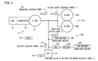
- FIG. 3 which illustrates the electric power distribution of the vehicle 10
- protective operations carried out by the ECU 26 with respect to the battery 24 will be described, in a state in which the rear wheels Wr of the vehicle 10 are driven by the first and second electric motors 22A, 22B, and with the motor traction control system, which forms an essential part of the present invention, being in a state of operation.
- the electric motor 14 (described by Fr-MOT (front wheel drive motor) in FIG. 3 , since it is a motor on the side of the front wheels Wf) is connected with respect to the internal combustion engine 12 (described by ENG) of the vehicle 10 through the aforementioned double clutch type transmission 18.
- the battery electric power Pbat [kW] of the battery 24 is defined so as to be operated at an outflowing electric power of - ⁇ [kW].
- the outflowing electric power is a discharging electric power
- the inflowing electric power is a charging electric power.
- a convention is adopted in which the battery electric power Pbat [kW] is negative on the discharging side, and is positive on the charging side. Accordingly, the outflowing electric power - ⁇ indicates a discharging electric power.
- the battery 24 includes a limit on the inflowing and outflowing electric power corresponding to the state of charge SOC [%] thereof.
- SOC state of charge
- the absolute value of the maximum value of the battery outflowing electric power -Pdmax which is a possible discharge electric power value
- the absolute value of the battery inflowing electric power Pcmax [kW] which is a possible charging electric power value
- a value in excess of the rated limit value a discharge electric power greater than -Pdmax, a charging electric power greater than Pcmax
- the ECU 26 calculates beforehand a constraint condition of the torque down amount TD [kW] for commanding the first and second electric motors 22A, 22B.
- Y ⁇ Y ⁇ TD
- Y ⁇ Y ⁇ TD
- the allowable electric power variation range (width) ⁇ [kW] from the battery operating point 210, as shown in FIG. 4 is represented by the following equation (2).
- ⁇ Z ⁇ ⁇ ⁇
- the outflowing electric power - ⁇ [kW] of the battery 24 in equation (2) can be understood from the value of the following equation (5), in which the left and right total electric power Y of the first and second electric motors 22A, 22B, and the auxiliary device load electric power L (consumed electric power of the auxiliary electrical devices) are subtracted from the generated electric power X.
- ⁇ ⁇ X ⁇ Y + L
- the limit on the maximum value of the battery outflowing electric power -Pdmax of the allowable output electric power which is a rated limit value in the negative direction, i.e., a current outflowing direction (an upward direction in FIG. 4 ) of the battery 24, can be considered in a similar manner.
- FIG. 5 is a block diagram showing a schematic configuration of a vehicle 10A according to a modified example of the present invention.
- a front wheel drive apparatus 16a of the vehicle 10A comprises the first and second electric motors 22A and 22B, which drive the left and right front wheels Wf (LWf, LWr) that are disposed on the front side of the vehicle 10A.
- a rear wheel drive apparatus 20a of the vehicle 10A comprises the electric motor 14, which is connected in series through the transmission 18 with the internal combustion engine 12 for driving the rear wheels Wr that are disposed on the rear side of the vehicle 10A.
- the above-described "motor traction control" can be applied in the same manner with respect to the first and second electric motors 22A, 22B of the vehicle 10A.
- a previously stored characteristic for example, the maximum battery outflowing electric power value -Pdmax [kW] and the maximum battery inflowing electric power value Pcmax [kW] shown in FIG. 6
- the target value of the charge amount SOC [%] is preferably reduced from the charge amount SOC1 to a target residual capacity value defined by a charge amount SOC2 of a smaller value, such that the allowable input electric power Z' at a time of low temperature returns to the allowable input electric power Z.
- the amount of decrease in the allowable input electric power Z which pertains to the constraint on the torque down amount TD of the battery 24, can be reduced.
- a left and right total limiting electric power Ylmt which is a limiting value (maximum value) of the left and right total electric power (Rr-MOT output electric power) Y consumed by the first and second electric motors 22A, 22B, becomes lower corresponding to a decrease in the battery temperature Tbat.
- the left and right total electric power (Rr-MOT output electric power) Y a value is adopted that lies within a range in which the left and right total limiting electric power Ylmt of the characteristic curve 212 of FIG. 7 is not exceeded.
- the torque down amount TD after the occurrence of slippage is in proportion to the torque amount at the time that slippage is generated, i.e., to the left and right total electric power (Rr-MOT output electric power) Y, or stated otherwise, considering that the slip amount increases as the left and right total electric power (Rr-MOT output electric power) Y becomes larger, a large torque down amount TD is required at the time of slippage.
- the torque down amount TD after the occurrence of slippage can be made smaller.
- the battery temperature Tbat is indicated on the horizontal axis
- an allowable input/output electric power of the battery 24, which has a positive correlation to the battery temperature Tbat may be indicated thereby.
- the left and right total limiting electric power Ylmt which is a limiting value (maximum value) of the left and right total electric power (Rr-MOT output electric power) Y consumed by the first and second electric motors 22A, 22B, may be controlled to become lower beforehand.
- a left and right total limiting electric power determining process i.e., the process of step S3 in the flowchart of FIG. 8
- the characteristic curve 212 of FIG. 7 is used, even though it is possible to protect the battery 24 by reducing the generated electric power amount of the electric motor 14, which functions as a generator, in a coordinated manner with the decrease (torque down) of the torque, which is the motive power generated by the first and second electric motors 22A, 22B, it is unnecessary for a complex cooperative control to be utilized.
- step S1 the ECU 26, by way of an output or the like from a non-illustrated ON/OFF switch, detects whether or not a traction mode for carrying out the traction control has been set. If it is judged that such a traction mode (under traction control) has been set (step S1: YES), then the torque down amount control process of steps S2 through S6 is implemented by the ECU 26.
- step S2 the battery temperature Tbat is detected.
- step S3 the left and right total limiting electric power Ylmt, which is a control value (maximum value) of the left and right total electric power Y [kW] corresponding to the battery temperature Tbat, is determined with reference to the characteristic curve 212 of FIG. 7 .
- step S4 as was described with reference to FIG. 6 , the target SOC is calculated corresponding to the battery temperature Tbat.
- step S5 in the inequality (10), based on the left and right total electric power Y, the constraint condition of the torque down amount TD, which is the allowable electric power variation range ⁇ of the total of the first and second electric motors 22A, 22B, is calculated beforehand.
- the present invention is not limited to the aforementioned embodiments including the vehicles 10, 10A (all wheel drive vehicles), which are capable of operating the electric motor 14 as a generator by the internal combustion engine 12 through the transmission 18, and simultaneously driving the front wheels Wf (or the rear wheels Wr) by the internal combustion engine 12 through the transmission 18, while the rear wheels Wr (or the front wheels Wf) are driven by the first and second electric motors 22A, 22B.
- the vehicles 10, 10A all wheel drive vehicles
- the features of the invention may be applied to a so-called (pure) series hybrid vehicle or to a range extender vehicle or the like, in which the rear wheels Wr (or the front wheels Wf) are driven by the first and second electric motors 22A, 22B, together with causing the generator to generate electric power by the internal combustion engine 12 (without driving the front wheels Wf and the rear wheels Wr by the internal combustion engine 12 through the transmission 18), and enabling rear wheel driving (or front wheel driving), or all wheel driving modes.
- a so-called (pure) series hybrid vehicle or to a range extender vehicle or the like in which the rear wheels Wr (or the front wheels Wf) are driven by the first and second electric motors 22A, 22B, together with causing the generator to generate electric power by the internal combustion engine 12 (without driving the front wheels Wf and the rear wheels Wr by the internal combustion engine 12 through the transmission 18), and enabling rear wheel driving (or front wheel driving), or all wheel driving modes.
Landscapes
- Engineering & Computer Science (AREA)
- Transportation (AREA)
- Mechanical Engineering (AREA)
- Chemical & Material Sciences (AREA)
- Combustion & Propulsion (AREA)
- Power Engineering (AREA)
- Automation & Control Theory (AREA)
- Life Sciences & Earth Sciences (AREA)
- Sustainable Development (AREA)
- Sustainable Energy (AREA)
- Electric Propulsion And Braking For Vehicles (AREA)
- Hybrid Electric Vehicles (AREA)
- Auxiliary Drives, Propulsion Controls, And Safety Devices (AREA)
Applications Claiming Priority (2)
| Application Number | Priority Date | Filing Date | Title |
|---|---|---|---|
| JP2013260105 | 2013-12-17 | ||
| PCT/JP2014/083232 WO2015093464A1 (ja) | 2013-12-17 | 2014-12-16 | 車両 |
Publications (2)
| Publication Number | Publication Date |
|---|---|
| EP3085593A1 true EP3085593A1 (de) | 2016-10-26 |
| EP3085593A4 EP3085593A4 (de) | 2017-12-06 |
Family
ID=53402810
Family Applications (1)
| Application Number | Title | Priority Date | Filing Date |
|---|---|---|---|
| EP14872352.1A Withdrawn EP3085593A4 (de) | 2013-12-17 | 2014-12-16 | Fahrzeug |
Country Status (8)
| Country | Link |
|---|---|
| US (1) | US9376006B2 (de) |
| EP (1) | EP3085593A4 (de) |
| JP (1) | JP5789069B1 (de) |
| KR (1) | KR20160099688A (de) |
| CN (2) | CN105829184B (de) |
| CA (1) | CA2933944A1 (de) |
| MY (1) | MY178568A (de) |
| WO (1) | WO2015093464A1 (de) |
Families Citing this family (19)
| Publication number | Priority date | Publication date | Assignee | Title |
|---|---|---|---|---|
| SE537127C2 (sv) * | 2013-05-24 | 2015-02-03 | BAE Systems Hägglunds Aktiebolag | Förfarande och system för styrning av drivlinan hos ett fordon |
| KR20150077732A (ko) * | 2013-12-30 | 2015-07-08 | 현대다이모스(주) | 차량의 하이브리드 변속기 및 그 제어방법 |
| JP6467320B2 (ja) * | 2015-09-09 | 2019-02-13 | 日立オートモティブシステムズ株式会社 | 蓄電池制御装置 |
| JP6118932B1 (ja) * | 2016-03-30 | 2017-04-19 | 本田技研工業株式会社 | 駆動装置 |
| US10816046B2 (en) * | 2016-08-15 | 2020-10-27 | Cnh Industrial America Llc | Clutch control for shared power dissipation |
| JP6617723B2 (ja) * | 2017-01-26 | 2019-12-11 | トヨタ自動車株式会社 | 制動装置 |
| JP6841078B2 (ja) * | 2017-02-21 | 2021-03-10 | トヨタ自動車株式会社 | 駆動力制御装置 |
| CN108528269B (zh) | 2017-02-21 | 2021-05-14 | 丰田自动车株式会社 | 驱动力控制装置 |
| US10099682B1 (en) | 2017-03-27 | 2018-10-16 | Ford Global Technologies, Llc | Controlling motor torque to reserve battery energy in a hybrid vehicle |
| JP6760513B2 (ja) * | 2017-10-24 | 2020-09-23 | 日産自動車株式会社 | 四輪駆動車の動力伝達装置 |
| JP7081959B2 (ja) * | 2018-03-30 | 2022-06-07 | 本田技研工業株式会社 | 車両電源システム |
| US11820254B2 (en) * | 2018-05-03 | 2023-11-21 | Ford Global Technologies, Llc | Hybrid electric vehicle with torque split regenerative braking |
| JP2020019328A (ja) * | 2018-07-31 | 2020-02-06 | マツダ株式会社 | 車両駆動装置 |
| US11499626B2 (en) * | 2019-12-09 | 2022-11-15 | Ford Global Technologies, Llc | System and method for changing to a low gear range of a four wheel drive vehicle |
| CN111422205B (zh) * | 2020-03-11 | 2022-04-08 | 宁波吉利汽车研究开发有限公司 | 一种混合动力装置的故障控制方法、系统及汽车 |
| GB2594285B (en) * | 2020-04-21 | 2022-09-14 | Jaguar Land Rover Ltd | Controlling electrical power consumption caused by wheel slip |
| US11493127B2 (en) * | 2020-08-31 | 2022-11-08 | Ford Global Technologies, Llc | System and method for reducing gear lash related torque disturbances |
| CN115476677A (zh) * | 2021-05-31 | 2022-12-16 | 比亚迪股份有限公司 | 驱动失效保护方法、整车控制器及汽车 |
| JPWO2023053205A1 (de) * | 2021-09-28 | 2023-04-06 |
Family Cites Families (27)
| Publication number | Priority date | Publication date | Assignee | Title |
|---|---|---|---|---|
| JPH05111111A (ja) | 1991-10-11 | 1993-04-30 | Honda Motor Co Ltd | 電気自動車及びその制御方法 |
| US5524079A (en) * | 1992-09-01 | 1996-06-04 | Matsushita Electric Industrial Co., Ltd. | Rear wheel steering angle controlling apparatus of four-wheel steering vehicle |
| JP3528452B2 (ja) * | 1996-08-14 | 2004-05-17 | トヨタ自動車株式会社 | 制動力制御装置 |
| DE19738690C2 (de) * | 1997-09-04 | 2002-05-29 | Bosch Gmbh Robert | Verfahren und Vorrichtung zur Steuerung der Bremsanlage eines Fahrzeugs |
| JP3983917B2 (ja) * | 1999-02-23 | 2007-09-26 | 本田技研工業株式会社 | 車両用電動式駆動装置 |
| US6629026B1 (en) * | 2002-04-12 | 2003-09-30 | Ford Motor Company | Hybrid electric vehicle with motor torque fill in |
| US6907337B2 (en) * | 2003-09-11 | 2005-06-14 | Ford Global Technologies, Llc | Vehicle torque resolution |
| JP4625632B2 (ja) * | 2003-12-25 | 2011-02-02 | 日立オートモティブシステムズ株式会社 | 車両駆動装置 |
| US7147078B2 (en) * | 2004-07-01 | 2006-12-12 | Ford Global Technologies, Llc | Charging a fluid accumulator while operating a hybrid vehicle powertrain including an engine and a pump/motor |
| US7689331B2 (en) * | 2004-12-01 | 2010-03-30 | Ise Corporation | Method of controlling engine stop-start operation for heavy-duty hybrid-electric and hybrid-hydraulic vehicles |
| JP4188348B2 (ja) * | 2005-08-10 | 2008-11-26 | 株式会社日立製作所 | 電動車両の走行制御装置および電動走行制御システム |
| JP2007245896A (ja) | 2006-03-15 | 2007-09-27 | Nissan Motor Co Ltd | 電動モータ式4輪駆動車両の異常電圧発生防止装置 |
| JP4481261B2 (ja) * | 2006-03-17 | 2010-06-16 | 本田技研工業株式会社 | ハイブリッド四輪駆動車両の制御装置 |
| JP4600381B2 (ja) * | 2006-10-19 | 2010-12-15 | トヨタ自動車株式会社 | 車両の車輪トルク推定装置及び制振制御装置 |
| JP5055992B2 (ja) * | 2006-12-11 | 2012-10-24 | 日産自動車株式会社 | ハイブリッド車両の駆動力制御装置 |
| JP4490458B2 (ja) * | 2007-06-15 | 2010-06-23 | 日立オートモティブシステムズ株式会社 | 回転電機の制御装置及び車両の駆動装置 |
| JP4412400B2 (ja) * | 2007-12-14 | 2010-02-10 | トヨタ自動車株式会社 | 車両用挙動制御装置 |
| RU2510337C2 (ru) | 2009-10-05 | 2014-03-27 | Хонда Мотор Ко., Лтд. | Транспортная приводная система |
| JP5414444B2 (ja) | 2009-10-05 | 2014-02-12 | 本田技研工業株式会社 | 車両用駆動装置 |
| JP5562277B2 (ja) * | 2011-03-07 | 2014-07-30 | Ntn株式会社 | 電気自動車 |
| JPWO2013005783A1 (ja) * | 2011-07-04 | 2015-02-23 | 本田技研工業株式会社 | 車両用駆動装置 |
| JP5908290B2 (ja) * | 2012-01-25 | 2016-04-26 | Ntn株式会社 | 電動車両の制御装置 |
| JP5652414B2 (ja) * | 2012-02-27 | 2015-01-14 | アイシン・エィ・ダブリュ株式会社 | 車両用駆動装置 |
| EP2829427A1 (de) * | 2012-03-21 | 2015-01-28 | Toyota Jidosha Kabushiki Kaisha | Antriebssteuerungsvorrichtung für ein hybridfahrzeug |
| JP5977982B2 (ja) | 2012-03-30 | 2016-08-24 | 本田技研工業株式会社 | 車両用駆動装置 |
| CN102975702B (zh) * | 2012-12-12 | 2018-02-16 | 奇瑞汽车股份有限公司 | 一种串联式再生制动控制方法 |
| CN105121239B (zh) * | 2013-04-10 | 2018-10-19 | 丰田自动车株式会社 | 混合动力车辆的控制装置 |
-
2014
- 2014-12-16 CN CN201480068416.5A patent/CN105829184B/zh active Active
- 2014-12-16 MY MYPI2016702244A patent/MY178568A/en unknown
- 2014-12-16 WO PCT/JP2014/083232 patent/WO2015093464A1/ja active Application Filing
- 2014-12-16 JP JP2015525672A patent/JP5789069B1/ja not_active Expired - Fee Related
- 2014-12-16 US US14/779,405 patent/US9376006B2/en active Active
- 2014-12-16 KR KR1020167019300A patent/KR20160099688A/ko active IP Right Grant
- 2014-12-16 CN CN201811514641.3A patent/CN110053471B/zh active Active
- 2014-12-16 CA CA2933944A patent/CA2933944A1/en not_active Abandoned
- 2014-12-16 EP EP14872352.1A patent/EP3085593A4/de not_active Withdrawn
Also Published As
| Publication number | Publication date |
|---|---|
| US9376006B2 (en) | 2016-06-28 |
| MY178568A (en) | 2020-10-16 |
| CA2933944A1 (en) | 2015-06-25 |
| JPWO2015093464A1 (ja) | 2017-03-16 |
| CN110053471B (zh) | 2022-08-02 |
| CN105829184A (zh) | 2016-08-03 |
| US20160039405A1 (en) | 2016-02-11 |
| KR20160099688A (ko) | 2016-08-22 |
| JP5789069B1 (ja) | 2015-10-07 |
| CN110053471A (zh) | 2019-07-26 |
| WO2015093464A1 (ja) | 2015-06-25 |
| CN105829184B (zh) | 2019-01-04 |
| EP3085593A4 (de) | 2017-12-06 |
Similar Documents
| Publication | Publication Date | Title |
|---|---|---|
| US9376006B2 (en) | Vehicle | |
| EP3088239B1 (de) | Fahrzeug | |
| CN109624962B (zh) | 混合动力车辆 | |
| EP1971512B1 (de) | Steuervorrichtung und steuerverfahren für ein fahrzeug | |
| US9457798B2 (en) | Hybrid vehicle and method for controlling same | |
| US8571737B2 (en) | Hybrid vehicle and control method thereof | |
| EP2559577B1 (de) | Hybridautomobil | |
| US8540604B1 (en) | Transmission control during regenerative braking | |
| CN104773174B (zh) | 用于控制混合动力总成系统中的蠕变扭矩的方法和装置 | |
| CA2895934C (en) | Hybrid vehicle and control method therefor | |
| US9254739B2 (en) | Vehicle | |
| JP6056627B2 (ja) | ハイブリッド車両の走行制御装置 | |
| JP2002345105A (ja) | 電気自動車 | |
| JP6334182B2 (ja) | 車両 | |
| JP6356419B2 (ja) | 車両 | |
| CN117284072A (zh) | 混合动力变速器直流电源(断连)连接件 | |
| JP2018020656A (ja) | ハイブリッド車両及びその制御方法 | |
| JP2007237821A (ja) | 動力出力装置およびこれを搭載する車両ならびに動力出力装置の制御方法 |
Legal Events
| Date | Code | Title | Description |
|---|---|---|---|
| PUAI | Public reference made under article 153(3) epc to a published international application that has entered the european phase |
Free format text: ORIGINAL CODE: 0009012 |
|
| 17P | Request for examination filed |
Effective date: 20160715 |
|
| AK | Designated contracting states |
Kind code of ref document: A1 Designated state(s): AL AT BE BG CH CY CZ DE DK EE ES FI FR GB GR HR HU IE IS IT LI LT LU LV MC MK MT NL NO PL PT RO RS SE SI SK SM TR |
|
| AX | Request for extension of the european patent |
Extension state: BA ME |
|
| DAX | Request for extension of the european patent (deleted) | ||
| RIC1 | Information provided on ipc code assigned before grant |
Ipc: B60W 30/02 20120101ALI20170724BHEP Ipc: B60L 11/14 20060101ALI20170724BHEP Ipc: B60W 20/15 20160101ALI20170724BHEP Ipc: B60W 20/00 20160101ALI20170724BHEP Ipc: B60L 11/12 20060101ALI20170724BHEP Ipc: B60L 11/18 20060101ALI20170724BHEP Ipc: B60K 6/442 20071001ALI20170724BHEP Ipc: B60K 6/547 20071001ALI20170724BHEP Ipc: B60W 20/11 20160101ALI20170724BHEP Ipc: B60K 6/52 20071001ALI20170724BHEP Ipc: B60W 10/08 20060101AFI20170724BHEP |
|
| A4 | Supplementary search report drawn up and despatched |
Effective date: 20171108 |
|
| RIC1 | Information provided on ipc code assigned before grant |
Ipc: B60K 6/52 20071001ALI20171102BHEP Ipc: B60W 20/15 20160101ALI20171102BHEP Ipc: B60K 6/547 20071001ALI20171102BHEP Ipc: B60W 30/02 20120101ALI20171102BHEP Ipc: B60L 11/18 20060101ALI20171102BHEP Ipc: B60L 11/14 20060101ALI20171102BHEP Ipc: B60W 20/00 20160101ALI20171102BHEP Ipc: B60W 10/08 20060101AFI20171102BHEP Ipc: B60K 6/442 20071001ALI20171102BHEP Ipc: B60L 11/12 20060101ALI20171102BHEP Ipc: B60W 20/11 20160101ALI20171102BHEP |
|
| STAA | Information on the status of an ep patent application or granted ep patent |
Free format text: STATUS: THE APPLICATION HAS BEEN WITHDRAWN |
|
| 18W | Application withdrawn |
Effective date: 20190412 |