EP3085481B1 - Bohr-fas-kombi-werkzeug - Google Patents
Bohr-fas-kombi-werkzeug Download PDFInfo
- Publication number
- EP3085481B1 EP3085481B1 EP16000490.9A EP16000490A EP3085481B1 EP 3085481 B1 EP3085481 B1 EP 3085481B1 EP 16000490 A EP16000490 A EP 16000490A EP 3085481 B1 EP3085481 B1 EP 3085481B1
- Authority
- EP
- European Patent Office
- Prior art keywords
- drill
- shank
- combined
- drill bit
- adapter sleeve
- Prior art date
- Legal status (The legal status is an assumption and is not a legal conclusion. Google has not performed a legal analysis and makes no representation as to the accuracy of the status listed.)
- Active
Links
- 238000005520 cutting process Methods 0.000 claims description 34
- 239000007787 solid Substances 0.000 claims description 21
- 239000000463 material Substances 0.000 claims description 17
- 230000006978 adaptation Effects 0.000 claims description 13
- 230000006835 compression Effects 0.000 claims description 8
- 238000007906 compression Methods 0.000 claims description 8
- 239000007769 metal material Substances 0.000 claims description 7
- 238000006073 displacement reaction Methods 0.000 claims description 2
- 239000000835 fiber Substances 0.000 description 13
- 229910052751 metal Inorganic materials 0.000 description 13
- 239000002184 metal Substances 0.000 description 13
- 229910000831 Steel Inorganic materials 0.000 description 9
- 239000010959 steel Substances 0.000 description 9
- 229910001315 Tool steel Inorganic materials 0.000 description 8
- 238000005553 drilling Methods 0.000 description 6
- 238000003754 machining Methods 0.000 description 6
- 230000005540 biological transmission Effects 0.000 description 3
- 229910000997 High-speed steel Inorganic materials 0.000 description 2
- XEEYBQQBJWHFJM-UHFFFAOYSA-N Iron Chemical compound [Fe] XEEYBQQBJWHFJM-UHFFFAOYSA-N 0.000 description 2
- 229910010037 TiAlN Inorganic materials 0.000 description 2
- ATJFFYVFTNAWJD-UHFFFAOYSA-N Tin Chemical compound [Sn] ATJFFYVFTNAWJD-UHFFFAOYSA-N 0.000 description 2
- NRTOMJZYCJJWKI-UHFFFAOYSA-N Titanium nitride Chemical compound [Ti]#N NRTOMJZYCJJWKI-UHFFFAOYSA-N 0.000 description 2
- 238000005452 bending Methods 0.000 description 2
- 238000003780 insertion Methods 0.000 description 2
- 230000037431 insertion Effects 0.000 description 2
- 238000004519 manufacturing process Methods 0.000 description 2
- 150000002739 metals Chemical class 0.000 description 2
- 238000000034 method Methods 0.000 description 2
- 229910000679 solder Inorganic materials 0.000 description 2
- 229910001018 Cast iron Inorganic materials 0.000 description 1
- 229910001065 Chromium-vanadium steel Inorganic materials 0.000 description 1
- 241000985128 Cladium mariscus Species 0.000 description 1
- 229910000760 Hardened steel Inorganic materials 0.000 description 1
- 229910000617 Mangalloy Inorganic materials 0.000 description 1
- RTAQQCXQSZGOHL-UHFFFAOYSA-N Titanium Chemical compound [Ti] RTAQQCXQSZGOHL-UHFFFAOYSA-N 0.000 description 1
- -1 Titanium aluminum nitrides Chemical class 0.000 description 1
- 241001106476 Violaceae Species 0.000 description 1
- 239000000853 adhesive Substances 0.000 description 1
- 230000001070 adhesive effect Effects 0.000 description 1
- RHZUVFJBSILHOK-UHFFFAOYSA-N anthracen-1-ylmethanolate Chemical compound C1=CC=C2C=C3C(C[O-])=CC=CC3=CC2=C1 RHZUVFJBSILHOK-UHFFFAOYSA-N 0.000 description 1
- 239000003830 anthracite Substances 0.000 description 1
- 230000004323 axial length Effects 0.000 description 1
- 239000002826 coolant Substances 0.000 description 1
- 238000005260 corrosion Methods 0.000 description 1
- 230000007797 corrosion Effects 0.000 description 1
- 230000008878 coupling Effects 0.000 description 1
- 238000010168 coupling process Methods 0.000 description 1
- 238000005859 coupling reaction Methods 0.000 description 1
- 229910003460 diamond Inorganic materials 0.000 description 1
- 239000010432 diamond Substances 0.000 description 1
- 239000003733 fiber-reinforced composite Substances 0.000 description 1
- 238000009434 installation Methods 0.000 description 1
- 229910052742 iron Inorganic materials 0.000 description 1
- 239000002245 particle Substances 0.000 description 1
- 239000004033 plastic Substances 0.000 description 1
- 230000002028 premature Effects 0.000 description 1
- 230000002265 prevention Effects 0.000 description 1
- 239000011150 reinforced concrete Substances 0.000 description 1
- 239000007779 soft material Substances 0.000 description 1
- 125000006850 spacer group Chemical group 0.000 description 1
- 239000010936 titanium Substances 0.000 description 1
- 229910052719 titanium Inorganic materials 0.000 description 1
Images


Classifications
-
- B—PERFORMING OPERATIONS; TRANSPORTING
- B23—MACHINE TOOLS; METAL-WORKING NOT OTHERWISE PROVIDED FOR
- B23B—TURNING; BORING
- B23B51/00—Tools for drilling machines
- B23B51/08—Drills combined with tool parts or tools for performing additional working
-
- B—PERFORMING OPERATIONS; TRANSPORTING
- B23—MACHINE TOOLS; METAL-WORKING NOT OTHERWISE PROVIDED FOR
- B23B—TURNING; BORING
- B23B51/00—Tools for drilling machines
- B23B51/02—Twist drills
-
- B—PERFORMING OPERATIONS; TRANSPORTING
- B23—MACHINE TOOLS; METAL-WORKING NOT OTHERWISE PROVIDED FOR
- B23B—TURNING; BORING
- B23B51/00—Tools for drilling machines
- B23B51/10—Bits for countersinking
- B23B51/102—Back spot-facing or chamfering
-
- B—PERFORMING OPERATIONS; TRANSPORTING
- B23—MACHINE TOOLS; METAL-WORKING NOT OTHERWISE PROVIDED FOR
- B23B—TURNING; BORING
- B23B51/00—Tools for drilling machines
- B23B51/10—Bits for countersinking
- B23B51/105—Deburring or countersinking of radial holes
-
- B—PERFORMING OPERATIONS; TRANSPORTING
- B23—MACHINE TOOLS; METAL-WORKING NOT OTHERWISE PROVIDED FOR
- B23B—TURNING; BORING
- B23B51/00—Tools for drilling machines
- B23B51/10—Bits for countersinking
- B23B51/108—Bits for countersinking having a centering drill
-
- B—PERFORMING OPERATIONS; TRANSPORTING
- B23—MACHINE TOOLS; METAL-WORKING NOT OTHERWISE PROVIDED FOR
- B23C—MILLING
- B23C3/00—Milling particular work; Special milling operations; Machines therefor
- B23C3/12—Trimming or finishing edges, e.g. deburring welded corners
-
- B—PERFORMING OPERATIONS; TRANSPORTING
- B23—MACHINE TOOLS; METAL-WORKING NOT OTHERWISE PROVIDED FOR
- B23B—TURNING; BORING
- B23B2220/00—Details of turning, boring or drilling processes
- B23B2220/04—Chamferring
-
- B—PERFORMING OPERATIONS; TRANSPORTING
- B23—MACHINE TOOLS; METAL-WORKING NOT OTHERWISE PROVIDED FOR
- B23B—TURNING; BORING
- B23B2220/00—Details of turning, boring or drilling processes
- B23B2220/08—Deburring
-
- B—PERFORMING OPERATIONS; TRANSPORTING
- B23—MACHINE TOOLS; METAL-WORKING NOT OTHERWISE PROVIDED FOR
- B23B—TURNING; BORING
- B23B2222/00—Materials of tools or workpieces composed of metals, alloys or metal matrices
- B23B2222/28—Details of hard metal, i.e. cemented carbide
-
- B—PERFORMING OPERATIONS; TRANSPORTING
- B23—MACHINE TOOLS; METAL-WORKING NOT OTHERWISE PROVIDED FOR
- B23B—TURNING; BORING
- B23B2251/00—Details of tools for drilling machines
- B23B2251/02—Connections between shanks and removable cutting heads
-
- B—PERFORMING OPERATIONS; TRANSPORTING
- B23—MACHINE TOOLS; METAL-WORKING NOT OTHERWISE PROVIDED FOR
- B23B—TURNING; BORING
- B23B2251/00—Details of tools for drilling machines
- B23B2251/24—Overall form of drilling tools
-
- B—PERFORMING OPERATIONS; TRANSPORTING
- B23—MACHINE TOOLS; METAL-WORKING NOT OTHERWISE PROVIDED FOR
- B23B—TURNING; BORING
- B23B2251/00—Details of tools for drilling machines
- B23B2251/50—Drilling tools comprising cutting inserts
-
- B—PERFORMING OPERATIONS; TRANSPORTING
- B23—MACHINE TOOLS; METAL-WORKING NOT OTHERWISE PROVIDED FOR
- B23B—TURNING; BORING
- B23B51/00—Tools for drilling machines
- B23B51/011—Micro drills
-
- Y—GENERAL TAGGING OF NEW TECHNOLOGICAL DEVELOPMENTS; GENERAL TAGGING OF CROSS-SECTIONAL TECHNOLOGIES SPANNING OVER SEVERAL SECTIONS OF THE IPC; TECHNICAL SUBJECTS COVERED BY FORMER USPC CROSS-REFERENCE ART COLLECTIONS [XRACs] AND DIGESTS
- Y10—TECHNICAL SUBJECTS COVERED BY FORMER USPC
- Y10T—TECHNICAL SUBJECTS COVERED BY FORMER US CLASSIFICATION
- Y10T408/00—Cutting by use of rotating axially moving tool
- Y10T408/83—Tool-support with means to move Tool relative to tool-support
- Y10T408/85—Tool-support with means to move Tool relative to tool-support to move radially
- Y10T408/858—Moving means including wedge, screw or cam
- Y10T408/8583—Moving means including wedge, screw or cam with resiliently urged Tool
Definitions
- the invention relates to a Bohr-Fas combined tool according to the preamble of claim 1.
- a tool is from the CN 202 317 174 U known.
- Bohr-Fas combination tool which is characterized in that in a cylindrical steel body, a drill bit is screwed.
- the drill bit consists of a conventional twist drill, which forms a cutting tip in a conventional manner and carries at its rear part a threaded projection which is screwed into an associated receiving bore at the front of the steel body.
- Bohr-Fas combined tool is therefore intended for attachment of blind and / or through holes in a workpiece in which after insertion into the bore a chamfer on at least one
- Bohr-Fas combination tool consists of a drill bit which is rotatably mounted in a body, wherein in the axial direction behind the drill bit a fiber knife is arranged, which is mounted spring-loaded in a knife window transversely to the longitudinal axis of the combination tool.
- the publication DE 1 477 224 A1 shows only a carbide drill, which are connected via a solder joint or a weld with the softer tool shank. This should be avoided in the invention.
- Bohr-Fas tool after the WO 20057037473 A1 is that in the drill shank, with the relatively large diameter, a large-area mechanics for the pivot drive of the deburring blade is arranged. This prohibits further miniaturization, because the use of a coil spring, which is wrapped around a pivot pin and is accommodated with its opposite end in a retaining bolt, which is also made adjustable, leads to a large-area mechanics.
- the CN 203 817 469 U discloses a combined tool for drilling and chamfering front and back.
- a drill tip is screwed onto the drill body in the manner of a quick coupling.
- These two parts are therefore not uniformly formed continuously, but connected to each other via a Gewindeschraubeur. Miniaturization of such an arrangement is therefore not possible because the screw thread of the drill bit in the drill body can not transmit high torques.
- the invention is therefore based on the object, a Bohr-Fas combination tool of the type mentioned in such a way that even in the deburring of small diameters, in particular less than 5 mm, a stable leadership of the drill and the transverse thereto working Fasmessers is possible and that the entire tool is more resilient and wear-resistant.
- the invention is characterized by the technical teaching of claim 1.
- Bohr-Fas combined tool is used in the design of a metal drill as a solid carbide drill.
- a body made of any tubular material such as a metal, plastic or other material, a trained solid carbide drill drill body used, the front end of the drill bit forms and carries in its directly adjacent to the drill bit area a transverse knife window for the there used deburring or chamfer ,
- the drill body consists of an integral and thus einstoff Korean spasigen solid carbide drill whose front end is formed as a drill bit and the rear end is now made of the same material as the drill bit and that in this Solid carbide drills now a knife window is used, in which the deburring or Fasmesser is arranged transversely displaceable.
- the drill shank consists of a hard metal and in this hard metal material immediately after the drill bit the knife window for the use of a deburring blade is arranged and further that the pivot drive of the deburring blade via a spring-loaded, axial pin takes place, the axial direction is arranged in the center of the drill shaft. It is dispensed with expansive torsion springs and instead used a aligned in the axial direction cylindrical compression spring. Only by such a small-sized drive the combined Bohr-Fas tool can be reduced in diameter of 5 millimeters.
- the drill bit forms, together with a drill shank attached to it in the form of a material, a drill body consisting of hard metal and / or hard coated, which has a central, continuous internal bore.
- This feature shows the present document WO 2005/037473 A1 not, because there is the drill shank made of a soft tool steel, at the front tip of the existing carbide cutting blades are soldered or screwed.
- the invention provides a continuous drill shank in a solid carbide drill such that the drill shank, and preferably also the drill bit, are formed integrally throughout and are made of the same hardened and / or hard-coated metal material.
- the present invention therefore has the advantage that the drill stem, because it consists of a hard metal, can be further miniaturized, because on the one hand in the drill shank the particularly space-saving pivot drive for the cutting blade is arranged and on the other hand, the drill shank even with miniaturization below 5 mm diameter can transmit so high torques that even the arrangement of a blade window in this drill shank with a transversely displaceable therein Fasmesser leads to no breakage of the drill shank even with transmission of high torques.
- the entire drill or drill body consisting of a drill bit and a drill shank attached to it in one piece, consists of a solid carbide material.
- the drill bit can be sharpened again after wear and not the fiber knife must be replaced because a multiple sharpening of the drill bit is possible.
- the entire solid carbide drill, consisting of drill bit and drill shank, according to the invention is designed as a drill body, which is designed as an insert part and which is inserted in a front forward frontally open receiving bore in a sleeve-shaped body and fixed there.
- the attachment of the solid carbide drill can be done in various ways.
- the solid carbide drill can be screwed, pressed, shrunk or clamped by means of transverse screws or the like clamping devices in the receiving bore of a body.
- the fiber knife connects directly to the drill spiral of the drill bit and only a relatively small axial gap of an adaptation length is necessary, the z. B. in the range of 0.01 to 2 mm.
- the rear main body is no longer designed as a sleeve which receives in the manner of a shrink or adhesive joint consisting of hard metal shank of the solid carbide drill, but an adapter sleeve is pressed directly into the drill shank and drive means in the adapter sleeve, namely a Compression spring are arranged with a suitable adjusting screw.
- the adapter sleeve has the same or a reduced diameter as the drill shaft.
- the diameter of the adapter sleeve for example in the range between 0.05 and 0.2 millimeters is smaller than the diameter of the drill shank.
- Such a dimensioning prevents any existing concentricity error in the connection of the two parts, affects the total circulation of the tool clamped when the clamping surfaces of the chuck extend beyond the length of the drill shank out and extend into the region of the adapter sleeve.
- the adapter sleeve is not clamped in the chuck, but only the drill shank.
- the outer diameter of the adapter sleeve relative to the chuck is free and does not affect the quality of the clamping.
- an adapter sleeve has the advantage that the existing hard metal drill stem can be clamped directly in the same or reduced diameter adapter sleeve in the chuck of a rotary drive, which in conventional Bohr-Fas combination tools is not possible, because with these only the base made of soft steel could be clamped in the chuck.
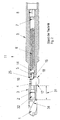
- FIGS. 1 and 2 show a conventional Bohr-Fas combination tool according to the prior art, wherein in a base body 3, a central longitudinal bore is arranged, in which a compression spring 6 is inserted.
- the compression spring 6 is pressed by means of a spacer pin 7 and a rearwardly arranged clamping screw 8 forward and presses against a cylindrical projection 14, which is preferably material integral with a control pin 5.
- the control pin 5 thus engages with its front tip 15 in an associated control groove 16 of a Fasmessers 4, which is thus arranged spring-loaded in the transverse direction in a knife window 25 transversely displaceable.
- the fiber knife 4 is formed in the forward and backward direction cutting. It therefore has a forwardly directed cutting edge 17 and a rearwardly directed cutting edge 18.
- the drilling helix 34 of the drill bit 1 thus ends before the receiving bore, in which the threaded projection 32 is screwed. But this has the disadvantage that an unfavorable, to be avoided adaptation length 31 is formed, which is formed between the rear end of the drill coil 34 and the front end of the blade window 25.
- this adaptation length 31 should be eliminated or at least decisively minimized.
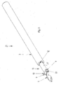
- the drill bit 1 is integrally connected to a drill shank 35 in the execution of a solid carbide drill, so that a continuous drill body 13 is formed at its front end a knife window 25 is arranged, in which the fiber knife 4 is slidably mounted.
- a central longitudinal bore is arranged, in which the control pin 5 engages, and the control pin 5 is closed at the rear by a neck or the head part 37 and connected thereto.
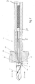
- FIG. 4 the approach 14 in a shortened body 3 and is there spring-loaded by the known compression spring 6.
- an existing solid carbide drill which has a front drill bit 1 and a drill shank 35, wherein in the region of the drill shank 35, the transverse knife window 25 is disposed, and it thus eliminates the adaptation length 31, because the chamfer now according to the invention in the drill shank 35 is arranged itself.
- a non-inventive use of the entire drill body 13 in a sleeve-shaped body 3 according to FIG. 4 takes place in a receiving bore 12, and the attachment in the receiving bore 12 can be made in any desired manner. It can there screwed the drill shank 35 of the drill body 13, snapped, shrunk, pressed or the like are set, in particular, a highly resilient positive connection is preferred.
- the chamfer can only be formed on one side cutting, namely with a rear cutting edge 18.
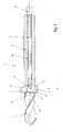
- Die FIGS. 3 to 7 show by way of example such a one-sided cutting chamfer 4.
- the illustrated Fasmesser 4 allows easy installation, which is particularly advantageous for small diameters, which are deburring.
- FIG. 6 It is shown that the fiber knife according to FIG. 5 has a tapered Ein Industriesprofilteil 9 and the entire fiber knife in the direction of arrow 24 in the knife window 25 downward according to FIG. 6 is inserted and the lead-in bevel 10 is supported on the spring-loaded in the knife window 25 into projecting tip 15 of the control pin 5 and slides along this slope along, until the tip 15 passes into the region of the cam 16 of the Fasmessers 4 and it locks in place.
- the Ein Swissprofilteil 9 is formed by two opposing transverse grooves 22, 23 cross-section weakened in the transverse direction and forms a breaker bar 20 so that at a bend of the Ein Industriesprofilteils 9 around the breaker bar 20 around the break web 20 breaks and thus the knife its final working position according to FIG. 7 receives.
- FIG. 5 also shows that adjoins the cutting edge 18 in a conventional manner a chip breaker 19.
- FIG. 7 shows a working position of a Bohr-Fas combi tool 21st
- Bohr-Fas combi tool 21 is withdrawn in the direction of arrow 27, so that the rear end of the Fasmessers 4 rests with its cutting edge 18 to the front edge of the hole and there attaches an inclined chamfer 30.
- an insertion bevel 33 is arranged, which ensures that when the drill with its drill bit 1 enters the workpiece bore 29, the fiber knife 4 is pushed back into the inner profile of the knife window 25 and no cutting action in the area of the workpiece bore 29 exerts.
- the invention also provides that a plurality of (more than one) Fasmesser 4 are arranged in a knife window 25 or - in another variant - that at the axial distance from the one knife window 25, a second and possibly a third knife window is arranged in the in each case a fiber knife is arranged. All Fasmesser can either be mounted transversely displaceable in the respective associated knife window of the common control pin 5 and controllable. In another embodiment, each chamfer may be assigned its own, spring-biased control bolt 5 in the axial direction.
- control pin 5 is spring-loaded and axially displaceable in the longitudinal bore 36 of the drill body 13 is arranged.
- FIG. 8 shows that an adapter sleeve 38, whose outer diameter 41 corresponds to the outer diameter 41 of the drill shank 35, in the region of Connection 39 is rotatably connected to the rear end face of the drill shank 35.
- the drive means for the displacement drive of the control pin 5 are arranged in the adapter sleeve 38.
- the control pin 5 is extended rearwardly by a head portion 37 of increased diameter, the head portion 37 engages in a central bore of the adapter sleeve 38.
- the head portion 37 At the head portion 37, one end of the compression spring 6 is supported, the other end is supported on the clamping screw 8, which is screwed into a threaded bore on the back of the adapter sleeve 38.
- the outer diameter 41 of the drill shank 35 is identical to the outer diameter 41 of the adapter sleeve 38, it is now possible to clamp the drill shank 35, which consists of a solid hard material, directly into the chuck 40 of a drive machine. It thus eliminates the base body 3 and the drive torque can be transmitted from the chuck 40 directly to the drill shank 35.
Landscapes
- Engineering & Computer Science (AREA)
- Mechanical Engineering (AREA)
- Drilling Tools (AREA)
- Earth Drilling (AREA)
Priority Applications (1)
| Application Number | Priority Date | Filing Date | Title |
|---|---|---|---|
| PL16000490T PL3085481T3 (pl) | 2015-04-24 | 2016-03-01 | Składane narzędzie do wiercenia i fazowania |
Applications Claiming Priority (1)
| Application Number | Priority Date | Filing Date | Title |
|---|---|---|---|
| DE102015005250.0A DE102015005250A1 (de) | 2015-04-24 | 2015-04-24 | Bohr-Fas-Kombi-Werkzeug |
Publications (2)
| Publication Number | Publication Date |
|---|---|
| EP3085481A1 EP3085481A1 (de) | 2016-10-26 |
| EP3085481B1 true EP3085481B1 (de) | 2019-10-09 |
Family
ID=55450952
Family Applications (1)
| Application Number | Title | Priority Date | Filing Date |
|---|---|---|---|
| EP16000490.9A Active EP3085481B1 (de) | 2015-04-24 | 2016-03-01 | Bohr-fas-kombi-werkzeug |
Country Status (8)
| Country | Link |
|---|---|
| US (1) | US10105765B2 (ko) |
| EP (1) | EP3085481B1 (ko) |
| JP (1) | JP6240917B2 (ko) |
| KR (1) | KR101882428B1 (ko) |
| CN (1) | CN106064248B (ko) |
| DE (1) | DE102015005250A1 (ko) |
| ES (1) | ES2765850T3 (ko) |
| PL (1) | PL3085481T3 (ko) |
Cited By (1)
| Publication number | Priority date | Publication date | Assignee | Title |
|---|---|---|---|---|
| DE102021101738B3 (de) | 2021-01-27 | 2022-04-28 | Audi Aktiengesellschaft | Verfahren zur Herstellung einer Werkstück-Durchgangsbohrung sowie Entgratungswerkzeug |
Families Citing this family (23)
| Publication number | Priority date | Publication date | Assignee | Title |
|---|---|---|---|---|
| DE102016105354B4 (de) * | 2016-03-22 | 2018-03-22 | Hartmetall-Werkzeugfabrik Paul Horn Gmbh | Spanabhebendes Werkzeug |
| DE102016110193A1 (de) * | 2016-06-02 | 2017-12-07 | Gühring KG | Drehwerkzeug mit austauschbaren Schneideinsätzen |
| US20190009348A1 (en) * | 2017-07-07 | 2019-01-10 | Cogsdill Tool Products, Inc. | Deburring tool |
| CN107570765B (zh) * | 2017-10-20 | 2023-09-08 | 江苏扬碟钻石工具有限公司 | 一种高效整体硬合金刀具 |
| CN109926627A (zh) * | 2017-12-15 | 2019-06-25 | 深圳市基石通用科技有限公司 | 一种切削刀具 |
| JP7111327B2 (ja) * | 2017-12-19 | 2022-08-02 | 有限会社齋藤設備工業所 | 回転工具 |
| CN108015326A (zh) * | 2017-12-30 | 2018-05-11 | 扬州海昌新材股份有限公司 | 一种可调式成形复合工装 |
| CN109822136B (zh) * | 2019-03-27 | 2024-03-29 | 盐城京奇刀具有限公司 | 一种长度可调节的一次成型双面倒角刀杆 |
| US11110525B2 (en) | 2019-05-24 | 2021-09-07 | The Boeing Company | Active-pressure hole finishing tool |
| US11213897B2 (en) | 2019-05-28 | 2022-01-04 | The Boeing Company | Method of assembling members of an assembly |
| CN110238431A (zh) * | 2019-06-05 | 2019-09-17 | 常州腾龙汽车零部件股份有限公司 | 一种高精度汽车冷凝器固定法兰储液罐多功能成型刀 |
| CN110549125B (zh) * | 2019-09-16 | 2021-06-18 | 苏州欧蒂华电子有限公司 | 一种管材自动化钻孔装置 |
| AT522998B1 (de) | 2019-09-27 | 2021-11-15 | Mate Gmbh | Vorrichtung zum kombinierten Fasen und Bohren von Werkstücken |
| CN110744109A (zh) * | 2019-10-30 | 2020-02-04 | 中国铁建重工集团股份有限公司 | 一种麻花钻装置及其加工方法 |
| KR102130468B1 (ko) * | 2020-01-17 | 2020-07-06 | 이호상 | 전후면 면취가공이 가능한 면취가공기 |
| KR102320734B1 (ko) | 2020-02-03 | 2021-11-01 | 박영후 | 공구길이 프리세터 |
| CN111940842B (zh) * | 2020-07-03 | 2022-10-25 | 中国第一汽车股份有限公司 | 一种可调节螺旋式浮动倒角刀及倒角方法 |
| CN111822790A (zh) * | 2020-07-17 | 2020-10-27 | 大连理工大学 | 一种深长管相贯处去毛刺专用装置及其刀具 |
| CN112893940A (zh) * | 2021-03-03 | 2021-06-04 | 铣立(上海)切削技术有限公司 | 一种快换钻尖正反倒角复合刀具 |
| CN113084219A (zh) * | 2021-04-02 | 2021-07-09 | 吉林圆方机械集团有限公司 | 一种钻孔及双面倒角装置 |
| CN113681058A (zh) * | 2021-08-26 | 2021-11-23 | 范月洋 | 一种用于钻头结构中的自动倒角机构 |
| US20230173589A1 (en) * | 2021-12-03 | 2023-06-08 | Howmet Aerospace Inc. | Blind fastener |
| EP4349512A1 (de) | 2022-10-05 | 2024-04-10 | HEULE Werkzeug AG | Zerspanungswerkzeug mit weiteren schaftseitigen neben-zerspanungswerkzeugen |
Family Cites Families (22)
| Publication number | Priority date | Publication date | Assignee | Title |
|---|---|---|---|---|
| US2373474A (en) * | 1942-10-14 | 1945-04-10 | Heyer Don | Chamfering tool |
| US3346894A (en) * | 1965-08-23 | 1967-10-17 | Jerome H Lemelson | Apparatus for controlling rotary and longitudinal movements of a combined tool carrying spindle |
| JPS5773015U (ko) * | 1980-10-16 | 1982-05-06 | ||
| JPS5773015A (en) | 1980-10-23 | 1982-05-07 | Sumitomo Chem Co Ltd | Water-dispersed curable composition |
| US5366372A (en) | 1993-11-29 | 1994-11-22 | Minnesota Mining And Manufacturing Company | Method and apparatus for debonding ceramic orthodontic brackets |
| JP3348751B2 (ja) * | 1994-11-17 | 2002-11-20 | 日本ビーテーエー株式会社 | 孔の面取加工用工具 |
| US5803679A (en) * | 1996-07-09 | 1998-09-08 | Heule; Ulf H. | Deburring tool for deburring the edges of boreholes |
| JP2002028809A (ja) * | 2000-07-13 | 2002-01-29 | Mitsubishi Materials Corp | 切削工具 |
| EP1622499A2 (en) * | 2003-04-17 | 2006-02-08 | Secant Medical, LLC | Tool with deployable cutting blade |
| KR100588294B1 (ko) * | 2003-11-06 | 2006-06-12 | (주)예스툴 | 상하 챔퍼링 기능을 가진 인서트 드릴 |
| WO2005037473A1 (en) * | 2003-10-15 | 2005-04-28 | Yestool Co., Ltd. | Insert drill with chamfering function |
| DE10357380A1 (de) * | 2003-12-05 | 2005-06-30 | Hilti Ag | Einsteckende für ein drehendes und/oder schlagendes Werkzeug |
| DE102004054989A1 (de) * | 2004-11-13 | 2006-05-18 | Heule, Ulf | Entgratwerkzeug zum Entgraten kleiner Bohrungsdruchmesser |
| IL166007A (en) * | 2004-12-27 | 2009-02-11 | Iscar Ltd | Scraping tool and cutting tool for it |
| CN1931550B (zh) * | 2006-10-11 | 2010-12-22 | 赖其淡 | 具有钻扩孔功能的钻头 |
| DE102008025642A1 (de) * | 2008-05-28 | 2009-12-03 | Heule, Ulf | Entgratwerkzeug zum Entgraten von Bohrungen |
| DE102009005275A1 (de) * | 2009-01-20 | 2010-07-22 | Heule, Ulf | Schneidmesser für spanabhebende Schneidwerkzeuge mit Bruchkerbe |
| JP5819669B2 (ja) * | 2011-08-04 | 2015-11-24 | スミス アンド ネフュー インコーポレーテッド | 切削工具 |
| CN202317174U (zh) * | 2011-11-04 | 2012-07-11 | 郑州市钻石精密制造有限公司 | 汽车发动机缸孔加工用的组合刀具 |
| WO2015025492A1 (ja) * | 2013-08-23 | 2015-02-26 | 株式会社ミヤナガ | 拡径孔部付き孔の穿孔装置 |
| CN203817469U (zh) * | 2014-05-07 | 2014-09-10 | 天合富奥汽车安全系统(长春)有限公司 | 钻孔及正反面倒角复合刀具 |
| DE202014103289U1 (de) * | 2014-07-16 | 2014-07-23 | Botek Präzisionsbohrtechnik Gmbh | Einlippenbohrer |
-
2015
- 2015-04-24 DE DE102015005250.0A patent/DE102015005250A1/de not_active Ceased
-
2016
- 2016-03-01 PL PL16000490T patent/PL3085481T3/pl unknown
- 2016-03-01 EP EP16000490.9A patent/EP3085481B1/de active Active
- 2016-03-01 ES ES16000490T patent/ES2765850T3/es active Active
- 2016-04-06 KR KR1020160042180A patent/KR101882428B1/ko active IP Right Grant
- 2016-04-19 JP JP2016083412A patent/JP6240917B2/ja active Active
- 2016-04-22 US US15/135,725 patent/US10105765B2/en active Active
- 2016-04-25 CN CN201610262649.XA patent/CN106064248B/zh active Active
Non-Patent Citations (1)
| Title |
|---|
| None * |
Cited By (1)
| Publication number | Priority date | Publication date | Assignee | Title |
|---|---|---|---|---|
| DE102021101738B3 (de) | 2021-01-27 | 2022-04-28 | Audi Aktiengesellschaft | Verfahren zur Herstellung einer Werkstück-Durchgangsbohrung sowie Entgratungswerkzeug |
Also Published As
| Publication number | Publication date |
|---|---|
| CN106064248A (zh) | 2016-11-02 |
| KR20160126865A (ko) | 2016-11-02 |
| PL3085481T3 (pl) | 2020-04-30 |
| EP3085481A1 (de) | 2016-10-26 |
| JP6240917B2 (ja) | 2017-12-06 |
| DE102015005250A1 (de) | 2016-10-27 |
| JP2016203367A (ja) | 2016-12-08 |
| US10105765B2 (en) | 2018-10-23 |
| CN106064248B (zh) | 2018-12-28 |
| US20160311037A1 (en) | 2016-10-27 |
| KR101882428B1 (ko) | 2018-07-26 |
| ES2765850T3 (es) | 2020-06-11 |
Similar Documents
| Publication | Publication Date | Title |
|---|---|---|
| EP3085481B1 (de) | Bohr-fas-kombi-werkzeug | |
| EP0859679B1 (de) | Bohrwerkzeug mit auswechselbarer spitze | |
| DE102005014422B4 (de) | Bohrgewindefräser | |
| DE69734937T2 (de) | Zweiteiliges drehendes Metallschneidwerkzeug und Methode zum Verbinden der Teile | |
| DE102010026271B4 (de) | Bohrwerkzeug | |
| EP1827742B1 (de) | Bohrer für ein bohr-/faswerkzeug und bohr-/faswerkzeug | |
| EP2318166B1 (de) | Werkzeug für spanende bearbeitung eines werkstücks | |
| DE102011106416B4 (de) | Bohr-Reib-Werkzeug | |
| EP2635394B1 (de) | Einlippenbohrer | |
| DE2145795A1 (de) | Schneidwerkzeug | |
| EP0283698B1 (de) | Innengekühltes Bohrwerkzeug aus Werkzeugspirale und Spannschaft | |
| CH678834A5 (ko) | ||
| EP1896207B1 (de) | Werkzeugsystem mit Schnittstelle | |
| EP3645201B1 (de) | Schneidwerkzeug und schneidkopf | |
| DE3108438C2 (de) | Bohrwerkzeug | |
| EP2266732B1 (de) | Spannsystem | |
| EP2076345A1 (de) | Modulares bohrwerkzeug und verfahren zu seiner herstellung | |
| DE102014207502B4 (de) | Rotationswerkzeug sowie Werkzeugkopf | |
| DE10205635B4 (de) | Werkzeugverbindung | |
| EP1654084B1 (de) | Bohrwerkzeug | |
| EP1362659B1 (de) | Werkzeug, Vorrichtung und Verfahren zum Entgraten von Bohrungen | |
| DE10321670A1 (de) | Werkzeug, Vorrichtung und Verfahren zum Entgraten von Bohrungen | |
| DE202010015045U1 (de) | Einlippenbohrer | |
| DE19735024A1 (de) | Bohrer für zusätzliche Rückseitenbearbeitung | |
| DE102009033508B4 (de) | Einlippenbohrer |
Legal Events
| Date | Code | Title | Description |
|---|---|---|---|
| PUAI | Public reference made under article 153(3) epc to a published international application that has entered the european phase |
Free format text: ORIGINAL CODE: 0009012 |
|
| AK | Designated contracting states |
Kind code of ref document: A1 Designated state(s): AL AT BE BG CH CY CZ DE DK EE ES FI FR GB GR HR HU IE IS IT LI LT LU LV MC MK MT NL NO PL PT RO RS SE SI SK SM TR |
|
| AX | Request for extension of the european patent |
Extension state: BA ME |
|
| STAA | Information on the status of an ep patent application or granted ep patent |
Free format text: STATUS: REQUEST FOR EXAMINATION WAS MADE |
|
| 17P | Request for examination filed |
Effective date: 20161209 |
|
| RBV | Designated contracting states (corrected) |
Designated state(s): AL AT BE BG CH CY CZ DE DK EE ES FI FR GB GR HR HU IE IS IT LI LT LU LV MC MK MT NL NO PL PT RO RS SE SI SK SM TR |
|
| STAA | Information on the status of an ep patent application or granted ep patent |
Free format text: STATUS: EXAMINATION IS IN PROGRESS |
|
| 17Q | First examination report despatched |
Effective date: 20180806 |
|
| GRAP | Despatch of communication of intention to grant a patent |
Free format text: ORIGINAL CODE: EPIDOSNIGR1 |
|
| STAA | Information on the status of an ep patent application or granted ep patent |
Free format text: STATUS: GRANT OF PATENT IS INTENDED |
|
| INTG | Intention to grant announced |
Effective date: 20190523 |
|
| GRAS | Grant fee paid |
Free format text: ORIGINAL CODE: EPIDOSNIGR3 |
|
| GRAA | (expected) grant |
Free format text: ORIGINAL CODE: 0009210 |
|
| STAA | Information on the status of an ep patent application or granted ep patent |
Free format text: STATUS: THE PATENT HAS BEEN GRANTED |
|
| AK | Designated contracting states |
Kind code of ref document: B1 Designated state(s): AL AT BE BG CH CY CZ DE DK EE ES FI FR GB GR HR HU IE IS IT LI LT LU LV MC MK MT NL NO PL PT RO RS SE SI SK SM TR |
|
| REG | Reference to a national code |
Ref country code: GB Ref legal event code: FG4D Free format text: NOT ENGLISH |
|
| REG | Reference to a national code |
Ref country code: CH Ref legal event code: EP |
|
| REG | Reference to a national code |
Ref country code: DE Ref legal event code: R096 Ref document number: 502016006951 Country of ref document: DE |
|
| REG | Reference to a national code |
Ref country code: IE Ref legal event code: FG4D Free format text: LANGUAGE OF EP DOCUMENT: GERMAN |
|
| REG | Reference to a national code |
Ref country code: AT Ref legal event code: REF Ref document number: 1188200 Country of ref document: AT Kind code of ref document: T Effective date: 20191115 |
|
| REG | Reference to a national code |
Ref country code: SE Ref legal event code: TRGR |
|
| REG | Reference to a national code |
Ref country code: NL Ref legal event code: MP Effective date: 20191009 |
|
| REG | Reference to a national code |
Ref country code: LT Ref legal event code: MG4D |
|
| PG25 | Lapsed in a contracting state [announced via postgrant information from national office to epo] |
Ref country code: NL Free format text: LAPSE BECAUSE OF FAILURE TO SUBMIT A TRANSLATION OF THE DESCRIPTION OR TO PAY THE FEE WITHIN THE PRESCRIBED TIME-LIMIT Effective date: 20191009 Ref country code: PT Free format text: LAPSE BECAUSE OF FAILURE TO SUBMIT A TRANSLATION OF THE DESCRIPTION OR TO PAY THE FEE WITHIN THE PRESCRIBED TIME-LIMIT Effective date: 20200210 Ref country code: LV Free format text: LAPSE BECAUSE OF FAILURE TO SUBMIT A TRANSLATION OF THE DESCRIPTION OR TO PAY THE FEE WITHIN THE PRESCRIBED TIME-LIMIT Effective date: 20191009 Ref country code: LT Free format text: LAPSE BECAUSE OF FAILURE TO SUBMIT A TRANSLATION OF THE DESCRIPTION OR TO PAY THE FEE WITHIN THE PRESCRIBED TIME-LIMIT Effective date: 20191009 Ref country code: NO Free format text: LAPSE BECAUSE OF FAILURE TO SUBMIT A TRANSLATION OF THE DESCRIPTION OR TO PAY THE FEE WITHIN THE PRESCRIBED TIME-LIMIT Effective date: 20200109 Ref country code: FI Free format text: LAPSE BECAUSE OF FAILURE TO SUBMIT A TRANSLATION OF THE DESCRIPTION OR TO PAY THE FEE WITHIN THE PRESCRIBED TIME-LIMIT Effective date: 20191009 Ref country code: BG Free format text: LAPSE BECAUSE OF FAILURE TO SUBMIT A TRANSLATION OF THE DESCRIPTION OR TO PAY THE FEE WITHIN THE PRESCRIBED TIME-LIMIT Effective date: 20200109 Ref country code: GR Free format text: LAPSE BECAUSE OF FAILURE TO SUBMIT A TRANSLATION OF THE DESCRIPTION OR TO PAY THE FEE WITHIN THE PRESCRIBED TIME-LIMIT Effective date: 20200110 |
|
| PG25 | Lapsed in a contracting state [announced via postgrant information from national office to epo] |
Ref country code: HR Free format text: LAPSE BECAUSE OF FAILURE TO SUBMIT A TRANSLATION OF THE DESCRIPTION OR TO PAY THE FEE WITHIN THE PRESCRIBED TIME-LIMIT Effective date: 20191009 Ref country code: RS Free format text: LAPSE BECAUSE OF FAILURE TO SUBMIT A TRANSLATION OF THE DESCRIPTION OR TO PAY THE FEE WITHIN THE PRESCRIBED TIME-LIMIT Effective date: 20191009 Ref country code: IS Free format text: LAPSE BECAUSE OF FAILURE TO SUBMIT A TRANSLATION OF THE DESCRIPTION OR TO PAY THE FEE WITHIN THE PRESCRIBED TIME-LIMIT Effective date: 20200224 |
|
| REG | Reference to a national code |
Ref country code: ES Ref legal event code: FG2A Ref document number: 2765850 Country of ref document: ES Kind code of ref document: T3 Effective date: 20200611 |
|
| PG25 | Lapsed in a contracting state [announced via postgrant information from national office to epo] |
Ref country code: AL Free format text: LAPSE BECAUSE OF FAILURE TO SUBMIT A TRANSLATION OF THE DESCRIPTION OR TO PAY THE FEE WITHIN THE PRESCRIBED TIME-LIMIT Effective date: 20191009 |
|
| REG | Reference to a national code |
Ref country code: DE Ref legal event code: R097 Ref document number: 502016006951 Country of ref document: DE |
|
| PG2D | Information on lapse in contracting state deleted |
Ref country code: IS |
|
| PG25 | Lapsed in a contracting state [announced via postgrant information from national office to epo] |
Ref country code: RO Free format text: LAPSE BECAUSE OF FAILURE TO SUBMIT A TRANSLATION OF THE DESCRIPTION OR TO PAY THE FEE WITHIN THE PRESCRIBED TIME-LIMIT Effective date: 20191009 Ref country code: DK Free format text: LAPSE BECAUSE OF FAILURE TO SUBMIT A TRANSLATION OF THE DESCRIPTION OR TO PAY THE FEE WITHIN THE PRESCRIBED TIME-LIMIT Effective date: 20191009 Ref country code: EE Free format text: LAPSE BECAUSE OF FAILURE TO SUBMIT A TRANSLATION OF THE DESCRIPTION OR TO PAY THE FEE WITHIN THE PRESCRIBED TIME-LIMIT Effective date: 20191009 Ref country code: IS Free format text: LAPSE BECAUSE OF FAILURE TO SUBMIT A TRANSLATION OF THE DESCRIPTION OR TO PAY THE FEE WITHIN THE PRESCRIBED TIME-LIMIT Effective date: 20200209 |
|
| PLBE | No opposition filed within time limit |
Free format text: ORIGINAL CODE: 0009261 |
|
| STAA | Information on the status of an ep patent application or granted ep patent |
Free format text: STATUS: NO OPPOSITION FILED WITHIN TIME LIMIT |
|
| PG25 | Lapsed in a contracting state [announced via postgrant information from national office to epo] |
Ref country code: SK Free format text: LAPSE BECAUSE OF FAILURE TO SUBMIT A TRANSLATION OF THE DESCRIPTION OR TO PAY THE FEE WITHIN THE PRESCRIBED TIME-LIMIT Effective date: 20191009 Ref country code: SM Free format text: LAPSE BECAUSE OF FAILURE TO SUBMIT A TRANSLATION OF THE DESCRIPTION OR TO PAY THE FEE WITHIN THE PRESCRIBED TIME-LIMIT Effective date: 20191009 |
|
| 26N | No opposition filed |
Effective date: 20200710 |
|
| PG25 | Lapsed in a contracting state [announced via postgrant information from national office to epo] |
Ref country code: MC Free format text: LAPSE BECAUSE OF FAILURE TO SUBMIT A TRANSLATION OF THE DESCRIPTION OR TO PAY THE FEE WITHIN THE PRESCRIBED TIME-LIMIT Effective date: 20191009 |
|
| REG | Reference to a national code |
Ref country code: CH Ref legal event code: PL |
|
| PG25 | Lapsed in a contracting state [announced via postgrant information from national office to epo] |
Ref country code: SI Free format text: LAPSE BECAUSE OF FAILURE TO SUBMIT A TRANSLATION OF THE DESCRIPTION OR TO PAY THE FEE WITHIN THE PRESCRIBED TIME-LIMIT Effective date: 20191009 |
|
| REG | Reference to a national code |
Ref country code: BE Ref legal event code: MM Effective date: 20200331 |
|
| PG25 | Lapsed in a contracting state [announced via postgrant information from national office to epo] |
Ref country code: LU Free format text: LAPSE BECAUSE OF NON-PAYMENT OF DUE FEES Effective date: 20200301 |
|
| PG25 | Lapsed in a contracting state [announced via postgrant information from national office to epo] |
Ref country code: IE Free format text: LAPSE BECAUSE OF NON-PAYMENT OF DUE FEES Effective date: 20200301 Ref country code: CH Free format text: LAPSE BECAUSE OF NON-PAYMENT OF DUE FEES Effective date: 20200331 Ref country code: LI Free format text: LAPSE BECAUSE OF NON-PAYMENT OF DUE FEES Effective date: 20200331 |
|
| PG25 | Lapsed in a contracting state [announced via postgrant information from national office to epo] |
Ref country code: BE Free format text: LAPSE BECAUSE OF NON-PAYMENT OF DUE FEES Effective date: 20200331 |
|
| REG | Reference to a national code |
Ref country code: AT Ref legal event code: MM01 Ref document number: 1188200 Country of ref document: AT Kind code of ref document: T Effective date: 20210301 |
|
| PG25 | Lapsed in a contracting state [announced via postgrant information from national office to epo] |
Ref country code: TR Free format text: LAPSE BECAUSE OF FAILURE TO SUBMIT A TRANSLATION OF THE DESCRIPTION OR TO PAY THE FEE WITHIN THE PRESCRIBED TIME-LIMIT Effective date: 20191009 Ref country code: MT Free format text: LAPSE BECAUSE OF FAILURE TO SUBMIT A TRANSLATION OF THE DESCRIPTION OR TO PAY THE FEE WITHIN THE PRESCRIBED TIME-LIMIT Effective date: 20191009 Ref country code: CY Free format text: LAPSE BECAUSE OF FAILURE TO SUBMIT A TRANSLATION OF THE DESCRIPTION OR TO PAY THE FEE WITHIN THE PRESCRIBED TIME-LIMIT Effective date: 20191009 |
|
| PG25 | Lapsed in a contracting state [announced via postgrant information from national office to epo] |
Ref country code: MK Free format text: LAPSE BECAUSE OF FAILURE TO SUBMIT A TRANSLATION OF THE DESCRIPTION OR TO PAY THE FEE WITHIN THE PRESCRIBED TIME-LIMIT Effective date: 20191009 |
|
| PG25 | Lapsed in a contracting state [announced via postgrant information from national office to epo] |
Ref country code: AT Free format text: LAPSE BECAUSE OF NON-PAYMENT OF DUE FEES Effective date: 20210301 |
|
| PGFP | Annual fee paid to national office [announced via postgrant information from national office to epo] |
Ref country code: FR Payment date: 20230320 Year of fee payment: 8 |
|
| PGFP | Annual fee paid to national office [announced via postgrant information from national office to epo] |
Ref country code: SE Payment date: 20230315 Year of fee payment: 8 Ref country code: PL Payment date: 20230217 Year of fee payment: 8 |
|
| PGFP | Annual fee paid to national office [announced via postgrant information from national office to epo] |
Ref country code: IT Payment date: 20230331 Year of fee payment: 8 Ref country code: ES Payment date: 20230414 Year of fee payment: 8 |
|
| PGFP | Annual fee paid to national office [announced via postgrant information from national office to epo] |
Ref country code: DE Payment date: 20240321 Year of fee payment: 9 Ref country code: CZ Payment date: 20240216 Year of fee payment: 9 Ref country code: GB Payment date: 20240322 Year of fee payment: 9 |