EP3080875B2 - Halterahmen für einen steckverbinder - Google Patents
Halterahmen für einen steckverbinder Download PDFInfo
- Publication number
- EP3080875B2 EP3080875B2 EP14830506.3A EP14830506A EP3080875B2 EP 3080875 B2 EP3080875 B2 EP 3080875B2 EP 14830506 A EP14830506 A EP 14830506A EP 3080875 B2 EP3080875 B2 EP 3080875B2
- Authority
- EP
- European Patent Office
- Prior art keywords
- module
- base
- holding frame
- frame
- base portion
- Prior art date
- Legal status (The legal status is an assumption and is not a legal conclusion. Google has not performed a legal analysis and makes no representation as to the accuracy of the status listed.)
- Active
Links
Images

Classifications
-
- H—ELECTRICITY
- H01—ELECTRIC ELEMENTS
- H01R—ELECTRICALLY-CONDUCTIVE CONNECTIONS; STRUCTURAL ASSOCIATIONS OF A PLURALITY OF MUTUALLY-INSULATED ELECTRICAL CONNECTING ELEMENTS; COUPLING DEVICES; CURRENT COLLECTORS
- H01R43/00—Apparatus or processes specially adapted for manufacturing, assembling, maintaining, or repairing of line connectors or current collectors or for joining electric conductors
- H01R43/20—Apparatus or processes specially adapted for manufacturing, assembling, maintaining, or repairing of line connectors or current collectors or for joining electric conductors for assembling or disassembling contact members with insulating base, case or sleeve
-
- H—ELECTRICITY
- H01—ELECTRIC ELEMENTS
- H01R—ELECTRICALLY-CONDUCTIVE CONNECTIONS; STRUCTURAL ASSOCIATIONS OF A PLURALITY OF MUTUALLY-INSULATED ELECTRICAL CONNECTING ELEMENTS; COUPLING DEVICES; CURRENT COLLECTORS
- H01R13/00—Details of coupling devices of the kinds covered by groups H01R12/70 or H01R24/00 - H01R33/00
- H01R13/46—Bases; Cases
- H01R13/502—Bases; Cases composed of different pieces
- H01R13/5025—Bases; Cases composed of different pieces one or more pieces being of resilient material
-
- H—ELECTRICITY
- H01—ELECTRIC ELEMENTS
- H01R—ELECTRICALLY-CONDUCTIVE CONNECTIONS; STRUCTURAL ASSOCIATIONS OF A PLURALITY OF MUTUALLY-INSULATED ELECTRICAL CONNECTING ELEMENTS; COUPLING DEVICES; CURRENT COLLECTORS
- H01R13/00—Details of coupling devices of the kinds covered by groups H01R12/70 or H01R24/00 - H01R33/00
- H01R13/46—Bases; Cases
- H01R13/502—Bases; Cases composed of different pieces
- H01R13/506—Bases; Cases composed of different pieces assembled by snap action of the parts
-
- H—ELECTRICITY
- H01—ELECTRIC ELEMENTS
- H01R—ELECTRICALLY-CONDUCTIVE CONNECTIONS; STRUCTURAL ASSOCIATIONS OF A PLURALITY OF MUTUALLY-INSULATED ELECTRICAL CONNECTING ELEMENTS; COUPLING DEVICES; CURRENT COLLECTORS
- H01R13/00—Details of coupling devices of the kinds covered by groups H01R12/70 or H01R24/00 - H01R33/00
- H01R13/46—Bases; Cases
- H01R13/514—Bases; Cases composed as a modular blocks or assembly, i.e. composed of co-operating parts provided with contact members or holding contact members between them
-
- H—ELECTRICITY
- H01—ELECTRIC ELEMENTS
- H01R—ELECTRICALLY-CONDUCTIVE CONNECTIONS; STRUCTURAL ASSOCIATIONS OF A PLURALITY OF MUTUALLY-INSULATED ELECTRICAL CONNECTING ELEMENTS; COUPLING DEVICES; CURRENT COLLECTORS
- H01R13/00—Details of coupling devices of the kinds covered by groups H01R12/70 or H01R24/00 - H01R33/00
- H01R13/46—Bases; Cases
- H01R13/516—Means for holding or embracing insulating body, e.g. casing, hoods
- H01R13/518—Means for holding or embracing insulating body, e.g. casing, hoods for holding or embracing several coupling parts, e.g. frames
-
- H—ELECTRICITY
- H01—ELECTRIC ELEMENTS
- H01R—ELECTRICALLY-CONDUCTIVE CONNECTIONS; STRUCTURAL ASSOCIATIONS OF A PLURALITY OF MUTUALLY-INSULATED ELECTRICAL CONNECTING ELEMENTS; COUPLING DEVICES; CURRENT COLLECTORS
- H01R13/00—Details of coupling devices of the kinds covered by groups H01R12/70 or H01R24/00 - H01R33/00
- H01R13/62—Means for facilitating engagement or disengagement of coupling parts or for holding them in engagement
- H01R13/627—Snap or like fastening
- H01R13/6275—Latching arms not integral with the housing
-
- H—ELECTRICITY
- H01—ELECTRIC ELEMENTS
- H01R—ELECTRICALLY-CONDUCTIVE CONNECTIONS; STRUCTURAL ASSOCIATIONS OF A PLURALITY OF MUTUALLY-INSULATED ELECTRICAL CONNECTING ELEMENTS; COUPLING DEVICES; CURRENT COLLECTORS
- H01R13/00—Details of coupling devices of the kinds covered by groups H01R12/70 or H01R24/00 - H01R33/00
- H01R13/62—Means for facilitating engagement or disengagement of coupling parts or for holding them in engagement
- H01R13/629—Additional means for facilitating engagement or disengagement of coupling parts, e.g. aligning or guiding means, levers, gas pressure electrical locking indicators, manufacturing tolerances
-
- H—ELECTRICITY
- H01—ELECTRIC ELEMENTS
- H01R—ELECTRICALLY-CONDUCTIVE CONNECTIONS; STRUCTURAL ASSOCIATIONS OF A PLURALITY OF MUTUALLY-INSULATED ELECTRICAL CONNECTING ELEMENTS; COUPLING DEVICES; CURRENT COLLECTORS
- H01R13/00—Details of coupling devices of the kinds covered by groups H01R12/70 or H01R24/00 - H01R33/00
- H01R13/62—Means for facilitating engagement or disengagement of coupling parts or for holding them in engagement
- H01R13/639—Additional means for holding or locking coupling parts together, after engagement, e.g. separate keylock, retainer strap
-
- H—ELECTRICITY
- H01—ELECTRIC ELEMENTS
- H01R—ELECTRICALLY-CONDUCTIVE CONNECTIONS; STRUCTURAL ASSOCIATIONS OF A PLURALITY OF MUTUALLY-INSULATED ELECTRICAL CONNECTING ELEMENTS; COUPLING DEVICES; CURRENT COLLECTORS
- H01R13/00—Details of coupling devices of the kinds covered by groups H01R12/70 or H01R24/00 - H01R33/00
- H01R13/648—Protective earth or shield arrangements on coupling devices, e.g. anti-static shielding
- H01R13/652—Protective earth or shield arrangements on coupling devices, e.g. anti-static shielding with earth pin, blade or socket
-
- H—ELECTRICITY
- H01—ELECTRIC ELEMENTS
- H01R—ELECTRICALLY-CONDUCTIVE CONNECTIONS; STRUCTURAL ASSOCIATIONS OF A PLURALITY OF MUTUALLY-INSULATED ELECTRICAL CONNECTING ELEMENTS; COUPLING DEVICES; CURRENT COLLECTORS
- H01R43/00—Apparatus or processes specially adapted for manufacturing, assembling, maintaining, or repairing of line connectors or current collectors or for joining electric conductors
- H01R43/18—Apparatus or processes specially adapted for manufacturing, assembling, maintaining, or repairing of line connectors or current collectors or for joining electric conductors for manufacturing bases or cases for contact members
-
- H—ELECTRICITY
- H01—ELECTRIC ELEMENTS
- H01R—ELECTRICALLY-CONDUCTIVE CONNECTIONS; STRUCTURAL ASSOCIATIONS OF A PLURALITY OF MUTUALLY-INSULATED ELECTRICAL CONNECTING ELEMENTS; COUPLING DEVICES; CURRENT COLLECTORS
- H01R43/00—Apparatus or processes specially adapted for manufacturing, assembling, maintaining, or repairing of line connectors or current collectors or for joining electric conductors
- H01R43/20—Apparatus or processes specially adapted for manufacturing, assembling, maintaining, or repairing of line connectors or current collectors or for joining electric conductors for assembling or disassembling contact members with insulating base, case or sleeve
- H01R43/22—Hand tools
-
- H—ELECTRICITY
- H01—ELECTRIC ELEMENTS
- H01R—ELECTRICALLY-CONDUCTIVE CONNECTIONS; STRUCTURAL ASSOCIATIONS OF A PLURALITY OF MUTUALLY-INSULATED ELECTRICAL CONNECTING ELEMENTS; COUPLING DEVICES; CURRENT COLLECTORS
- H01R12/00—Structural associations of a plurality of mutually-insulated electrical connecting elements, specially adapted for printed circuits, e.g. printed circuit boards [PCB], flat or ribbon cables, or like generally planar structures, e.g. terminal strips, terminal blocks; Coupling devices specially adapted for printed circuits, flat or ribbon cables, or like generally planar structures; Terminals specially adapted for contact with, or insertion into, printed circuits, flat or ribbon cables, or like generally planar structures
- H01R12/70—Coupling devices
- H01R12/7005—Guiding, mounting, polarizing or locking means; Extractors
- H01R12/7011—Locking or fixing a connector to a PCB
-
- H—ELECTRICITY
- H01—ELECTRIC ELEMENTS
- H01R—ELECTRICALLY-CONDUCTIVE CONNECTIONS; STRUCTURAL ASSOCIATIONS OF A PLURALITY OF MUTUALLY-INSULATED ELECTRICAL CONNECTING ELEMENTS; COUPLING DEVICES; CURRENT COLLECTORS
- H01R12/00—Structural associations of a plurality of mutually-insulated electrical connecting elements, specially adapted for printed circuits, e.g. printed circuit boards [PCB], flat or ribbon cables, or like generally planar structures, e.g. terminal strips, terminal blocks; Coupling devices specially adapted for printed circuits, flat or ribbon cables, or like generally planar structures; Terminals specially adapted for contact with, or insertion into, printed circuits, flat or ribbon cables, or like generally planar structures
- H01R12/70—Coupling devices
- H01R12/91—Coupling devices allowing relative movement between coupling parts, e.g. floating or self aligning
-
- H—ELECTRICITY
- H01—ELECTRIC ELEMENTS
- H01R—ELECTRICALLY-CONDUCTIVE CONNECTIONS; STRUCTURAL ASSOCIATIONS OF A PLURALITY OF MUTUALLY-INSULATED ELECTRICAL CONNECTING ELEMENTS; COUPLING DEVICES; CURRENT COLLECTORS
- H01R24/00—Two-part coupling devices, or either of their cooperating parts, characterised by their overall structure
- H01R24/60—Contacts spaced along planar side wall transverse to longitudinal axis of engagement
- H01R24/62—Sliding engagements with one side only, e.g. modular jack coupling devices
-
- H—ELECTRICITY
- H01—ELECTRIC ELEMENTS
- H01R—ELECTRICALLY-CONDUCTIVE CONNECTIONS; STRUCTURAL ASSOCIATIONS OF A PLURALITY OF MUTUALLY-INSULATED ELECTRICAL CONNECTING ELEMENTS; COUPLING DEVICES; CURRENT COLLECTORS
- H01R4/00—Electrically-conductive connections between two or more conductive members in direct contact, i.e. touching one another; Means for effecting or maintaining such contact; Electrically-conductive connections having two or more spaced connecting locations for conductors and using contact members penetrating insulation
- H01R4/26—Connections in which at least one of the connecting parts has projections which bite into or engage the other connecting part in order to improve the contact
-
- H—ELECTRICITY
- H01—ELECTRIC ELEMENTS
- H01R—ELECTRICALLY-CONDUCTIVE CONNECTIONS; STRUCTURAL ASSOCIATIONS OF A PLURALITY OF MUTUALLY-INSULATED ELECTRICAL CONNECTING ELEMENTS; COUPLING DEVICES; CURRENT COLLECTORS
- H01R9/00—Structural associations of a plurality of mutually-insulated electrical connecting elements, e.g. terminal strips or terminal blocks; Terminals or binding posts mounted upon a base or in a case; Bases therefor
- H01R9/16—Fastening of connecting parts to base or case; Insulating connecting parts from base or case
-
- H—ELECTRICITY
- H01—ELECTRIC ELEMENTS
- H01R—ELECTRICALLY-CONDUCTIVE CONNECTIONS; STRUCTURAL ASSOCIATIONS OF A PLURALITY OF MUTUALLY-INSULATED ELECTRICAL CONNECTING ELEMENTS; COUPLING DEVICES; CURRENT COLLECTORS
- H01R9/00—Structural associations of a plurality of mutually-insulated electrical connecting elements, e.g. terminal strips or terminal blocks; Terminals or binding posts mounted upon a base or in a case; Bases therefor
- H01R9/22—Bases, e.g. strip, block, panel
- H01R9/226—Bases, e.g. strip, block, panel comprising a plurality of conductive flat strips providing connection between wires or components
-
- Y—GENERAL TAGGING OF NEW TECHNOLOGICAL DEVELOPMENTS; GENERAL TAGGING OF CROSS-SECTIONAL TECHNOLOGIES SPANNING OVER SEVERAL SECTIONS OF THE IPC; TECHNICAL SUBJECTS COVERED BY FORMER USPC CROSS-REFERENCE ART COLLECTIONS [XRACs] AND DIGESTS
- Y10—TECHNICAL SUBJECTS COVERED BY FORMER USPC
- Y10T—TECHNICAL SUBJECTS COVERED BY FORMER US CLASSIFICATION
- Y10T29/00—Metal working
- Y10T29/49—Method of mechanical manufacture
- Y10T29/49002—Electrical device making
- Y10T29/49117—Conductor or circuit manufacturing
- Y10T29/49124—On flat or curved insulated base, e.g., printed circuit, etc.
- Y10T29/4913—Assembling to base an electrical component, e.g., capacitor, etc.
- Y10T29/49133—Assembling to base an electrical component, e.g., capacitor, etc. with component orienting
- Y10T29/49137—Different components
-
- Y—GENERAL TAGGING OF NEW TECHNOLOGICAL DEVELOPMENTS; GENERAL TAGGING OF CROSS-SECTIONAL TECHNOLOGIES SPANNING OVER SEVERAL SECTIONS OF THE IPC; TECHNICAL SUBJECTS COVERED BY FORMER USPC CROSS-REFERENCE ART COLLECTIONS [XRACs] AND DIGESTS
- Y10—TECHNICAL SUBJECTS COVERED BY FORMER USPC
- Y10T—TECHNICAL SUBJECTS COVERED BY FORMER US CLASSIFICATION
- Y10T29/00—Metal working
- Y10T29/49—Method of mechanical manufacture
- Y10T29/49002—Electrical device making
- Y10T29/49117—Conductor or circuit manufacturing
- Y10T29/49169—Assembling electrical component directly to terminal or elongated conductor
-
- Y—GENERAL TAGGING OF NEW TECHNOLOGICAL DEVELOPMENTS; GENERAL TAGGING OF CROSS-SECTIONAL TECHNOLOGIES SPANNING OVER SEVERAL SECTIONS OF THE IPC; TECHNICAL SUBJECTS COVERED BY FORMER USPC CROSS-REFERENCE ART COLLECTIONS [XRACs] AND DIGESTS
- Y10—TECHNICAL SUBJECTS COVERED BY FORMER USPC
- Y10T—TECHNICAL SUBJECTS COVERED BY FORMER US CLASSIFICATION
- Y10T29/00—Metal working
- Y10T29/49—Method of mechanical manufacture
- Y10T29/49002—Electrical device making
- Y10T29/49117—Conductor or circuit manufacturing
- Y10T29/49204—Contact or terminal manufacturing
- Y10T29/49208—Contact or terminal manufacturing by assembling plural parts
- Y10T29/49217—Contact or terminal manufacturing by assembling plural parts by elastic joining
-
- Y—GENERAL TAGGING OF NEW TECHNOLOGICAL DEVELOPMENTS; GENERAL TAGGING OF CROSS-SECTIONAL TECHNOLOGIES SPANNING OVER SEVERAL SECTIONS OF THE IPC; TECHNICAL SUBJECTS COVERED BY FORMER USPC CROSS-REFERENCE ART COLLECTIONS [XRACs] AND DIGESTS
- Y10—TECHNICAL SUBJECTS COVERED BY FORMER USPC
- Y10T—TECHNICAL SUBJECTS COVERED BY FORMER US CLASSIFICATION
- Y10T29/00—Metal working
- Y10T29/53—Means to assemble or disassemble
- Y10T29/5313—Means to assemble electrical device
- Y10T29/53252—Means to simultaneously fasten three or more parts
Definitions
- the invention relates to a holding frame according to the preamble of the independent main claim 1.
- the invention relates to a method according to the preamble of independent claim 6 and a method according to the preamble of independent claim 13.
- Such holding frames are required to accommodate several similar and/or different modules.
- These modules can, for example, be insulating bodies intended as contact carriers for electronic and electrical, and possibly also for optical and/or pneumatic contacts. It is particularly important that the holding frame enables proper protective earthing in accordance with the connector standard EN61984, for example, for inserting the holding frame equipped with modules into metallic connector housings.
- DE 2736079 A1 refers to the fastening of terminal blocks or connection modules made of rigid insulating material by snapping them into place and securing them in place on a metallic support rail, which may be asymmetrical and which may be formed by a U-shaped profile with two inwardly projecting projections which may be offset in height from each other and from the central part of the U-shaped profile.
- DE 2736079 A1 a snap-in terminal block or a connection module for electrical cables, the terminal block being provided with grooves on its two end edges, which run parallel to the longitudinal direction of a support rail, for assembling such terminal blocks, each of which cooperates with internal horizontal projections provided near the free ends of the two legs of a metallic U-shaped support profile, the grooves being insertable at different distances from the base of the profile against the action of at least one transverse leaf spring having two parts compressible towards the base and against the rear leg of the profile, respectively, and a free end of which is capable of being displaced transversely inside a groove formed in the thickness of the metal of the profile, parallel to the base at the connection point of this base with an inner part of increased thickness of the front leg of this profile, such that the depth of this groove, with respect to the distance between the internal projections, is sufficient to ensure the compression of the curved central part of the transverse leaf springs, which is necessary to enable the inwardly projecting projections to enter the interior of the grooves of the end faces
- DE 295 080 95 U1 relates to a module insertion frame for receiving contact modules for insertion into plug connector housings, with a frame body consisting of two cheek parts and two head pieces, each of which is parallel and opposite one another and forms a receiving opening for the contact modules, with holding means on the cheek parts, by which the contact modules are fixed and held, with guide means on the head pieces, which on the one hand comprise a positive/male guide element and on the other hand a negative/female guide element, and with protective contact means which are formed on the head pieces, wherein the protective contact means are formed by one of the guide elements itself, which is connected in one piece to the frame body, and a single protective contact spring which is fastened to the other of the guide elements.
- a holding frame for holding connector modules and for installation in connector housings or for screwing to wall surfaces is known, wherein the connector modules are inserted into the holding frame and holding means on the connector modules interact with recesses provided on opposite wall parts (side parts) of the holding frame, wherein the recesses are designed as openings in the side parts of the holding frame that are closed on all sides, wherein the holding frame consists of two halves that are connected to one another in an articulated manner, wherein the separation of the holding frame is provided transversely to the side parts of the frame, and wherein joints are arranged in the fastening ends of the holding frame in such a way that when the holding frame is screwed onto a fastening surface, the frame parts are aligned in such a way that the side parts of the holding frame are aligned at right angles to the fastening surface and the connector modules have a positive connection with the holding frame via the holding means.
- such holding frames are usually manufactured using a die-casting process, in particular
- the printed matter EP 2 581 991 A1 discloses a holding frame for connector modules, which has two frame halves which can be locked together by linearly displacing one frame half relative to the other frame half in a sliding direction, wherein corresponding locking means are provided on the frame halves, which, during linear displacement, cause the two frame halves to lock together in two different locking positions, in which the frame halves are spaced at different distances from each other.
- the printed matter EP 1 801 927 B1 discloses a holding frame consisting of a one-piece plastic injection-molded part.
- the holding frame is designed as a circumferential collar and has several wall segments separated by slots on its plug-in side. Two opposing wall segments each form an insertion area for a plug-in module, with the wall segments having window-like openings that serve to accommodate projections molded onto the narrow sides of the modules.
- a guide groove is provided in each wall segment. The guide groove is formed above the openings by means of an outwardly offset window web that has an insertion bevel on the inside.
- the plug-in modules have locking arms that are molded onto the narrow sides in the direction of the cable connections and lock below the lateral collar wall, so that two independent locking means fix the plug-in modules in the holding frame.
- a disadvantage of this prior art is, firstly, that it involves a plastic retaining frame, which, by its nature, is not suitable for protective earthing and therefore not suitable for installation in metallic connector housings.
- metallic connector housings requires such protective earthing, and this is necessary in many cases due to their mechanical robustness, temperature resistance, and electrically shielding properties, and is therefore desired by customers.
- the production of the aforementioned plastic retaining frames using injection molding is at least difficult and only possible with great effort.
- the heat resistance of such a plastic retaining frame is not always sufficient for special applications, for example, near a blast furnace.
- the plastic material and shape, in particular the thickness of the retaining frame are primarily determined by the requirements for flexibility and not by those for temperature resistance.
- the object of the invention is to provide a design for a holding frame which, on the one hand, has good heat resistance and high mechanical robustness and which, in particular, also enables appropriate protective earthing, in particular a PE ("Protection Earth”), when installed in a metallic connector housing and, on the other hand, also ensures convenient operability, in particular when replacing individual modules.
- PE Protectection Earth
- Such a holding frame is suitable for heavy-duty industrial connectors and can be made at least partially of an electrically conductive material. This allows for protective grounding, which can be achieved, for example, by having a PE contact in the holding frame or at least being equipped with such a PE contact.
- the holding frame has a base section and a deformation section, which are at least partially formed from different materials.
- the base section serves to fix a received module in a plane.
- the deformation section can assume an insertion state and a holding state, wherein the insertion state allows insertion of at least one module into the holding frame in a direction transverse to the plane, wherein a received module is fixed in the holding state.
- the support frame comprises a base frame as the base section and two cheek parts as the deformation section.
- the base frame can then be made of a different material than the cheek parts and thus advantageously possesses less elasticity and thus greater rigidity than the cheek parts.
- the cheek parts can be made of a material that, according to its stress/strain diagram, is more elastic, i.e., has a lower modulus of elasticity, than the material from which the base section, in particular the base frame, is formed.
- the material of the base section can be stiffer than the material from which the deformation section is formed.
- the material of the base frame, according to its stress/strain diagram can have a modulus of elasticity that is greater than the modulus of elasticity of the material from which the cheek parts are formed.
- the value of the modulus of elasticity is greater the more resistance a material offers to elastic deformation.
- the material from which the deformation section is formed can, according to its stress/strain diagram, have a larger elastic range than the material from which the base section is formed.
- the base section in particular the base frame, can be designed to be stiff, in particular ideally rigid.
- cheek parts can be designed to be spring-elastic and can advantageously be made of a spring-elastic sheet metal.
- a spring-elastic sheet is understood to be a sheet that has spring-elastic properties, such as reversible deformability, in particular when a corresponding restoring force is applied, for example a sheet that is made of spring steel or a comparable material.
- One advantage of the invention is that the modules can be inserted and removed from the support frame individually and with minimal effort, which particularly facilitates manual assembly.
- the spring-elastic properties of the side panels allow modules to be inserted or removed individually with minimal effort.
- the rigidity of the base frame provides the necessary mechanical stability for holding the inserted modules.
- the use of one or more metallic materials ensures high temperature resistance, compared for example with plastic, and also particularly high mechanical robustness of the holding frame.
- a further advantage of using one or more metallic materials is that the holding frame enables protective earthing for electrical safety, in particular a PE protective earthing of a metallic connector housing into which the holding frame is inserted.
- This shielding can provide protection against external interference fields.
- it can also be shielding to prevent or reduce emitted interference, i.e. to protect the environment against interference fields from the connector. In other words, not only are the signals transmitted by the modules protected from external interference fields, but the environment is also protected from interference caused by current flowing through the modules.
- the holding frame is, on the one hand, particularly heat-resistant and, on the other hand, through the use of spring-elastic sheet metal, for example, it still has a sufficiently high elasticity in the required places to allow the modules to be inserted and removed from the module frame individually and with little effort. It is therefore particularly advantageous if the holding frame has spring-elastic sheet metal in suitable places, as this makes it significantly more heat-resistant than a plastic frame that is otherwise functionally comparable from a mechanical point of view, while at least being as elastic. Associated modules can be designed accordingly compactly, so that they can still be made of plastic and yet are relatively heat-resistant.
- the support frame has several different regions, for example, a first and a second region, which have different elasticities from one another, because it can then specifically apply a higher section modulus in the region of the highest bending stress.
- the first region can correspond to the base section.
- the second region can correspond to the deformation section.
- These different regions can, for example, be formed from different materials and thus preferably have different material properties, in particular different moduli of elasticity.
- the second region in particular the deformation section, can therefore have greater elasticity than the first region, which corresponds in particular to the base section.
- the first region can thus, conversely, have greater rigidity than the second region.
- the first region can be rigid and the second region can be spring-elastic.
- Such elasticity or rigidity can, on the one hand, as already mentioned, be achieved by the material used in each case and/or, on the other hand, it can also be achieved by the geometric shape of these regions, in particular of the base section and the deformation section.
- the first region in particular the base section, can be formed from a rigid material, for example from a zinc alloy or from an aluminum alloy or from a copper alloy.
- the second region, in particular the deformation section can be formed from a spring-elastic material and thus, for example, consist of a spring-elastic steel sheet.
- the first region, in particular the base section can be produced in a casting process, for example in a zinc die-casting or aluminum die-casting process, or can also be produced by milling from, for example, a copper alloy.
- the first region, in particular the base section can preferably be the circumferential base frame.
- the base frame can therefore be a zinc die-cast part, in particular.
- the base frame can be essentially rectangular in cross-section, i.e. it has two end faces lying parallel to one another and, at right angles to this, two side parts lying parallel to one another, wherein the two end faces are shorter than the two side parts. Both the end faces and the side parts can have an essentially rectangular shape.
- the second region in particular the deformation section, can be formed with two separate cheek parts, each of which preferably consists of a resilient sheet metal part.
- the two cheek parts can optionally be made of the same material, in particular resilient sheet metal, and also have the same thickness.
- the two cheek parts can preferably be punched from the same sheet metal.
- Each cheek part can be essentially flat and preferably have a rectangular basic shape. Thus, it has two opposing, long edges, namely a first and a second edge, and at right angles to them, two opposing, short edges, namely a third and a fourth edge.
- the cheek part has, in particular, preferably straight slots that begin at regular intervals on its first edge and run preferably at right angles thereto towards the second edge into the cheek part, whereby free-standing tabs are formed in the cheek part.
- a locking window is arranged in each of these tabs as a locking element. These locking windows are provided to receive locking lugs of inserted modules in order to lock the modules in the holding frame.
- each cheek part can have several fastening elements, in particular fastening recesses, preferably of a round shape, for fastening to the base frame.
- Each of the two cheek pieces can advantageously be attached to the base frame on an outer side of one of the two side pieces, so that two spring-elastic tabs of the two cheek pieces are symmetrically opposite each other. Furthermore, these tabs can be bent slightly outward toward their ends, i.e., away from the base frame and thus from each other, to facilitate the insertion of a module.
- the base frame can have fastening means, such as round fastening pins, on the corresponding side part, preferably on both side parts. These fastening means can engage in the fastening recesses of the corresponding cheek part and thus hold the cheek parts to the base frame, for example by locking and/or by a positive and non-positive connection. Additionally or alternatively, the cheek parts can be attached to the base frame by gluing, welding, soldering, riveting and/or screwing, or by any other fastening method.
- fastening means such as round fastening pins
- the associated modules can be essentially cuboid-shaped and can each have a width on two opposite end faces that corresponds to the width of a tab.
- Each module advantageously has a locking lug on each of its two end faces, which can also be essentially cuboid-shaped.
- Each of the spring-elastic tabs of the holding frame advantageously has a locking window, which can be essentially rectangular and is provided for the preferably form-fitting reception of such a locking lug.
- the two locking lugs of a module can differ from one another, for example in their shape and/or size, in particular in their length.
- the tabs on both sides of the holding frame can have corresponding windows, which also differ from one another and whose size and/or shape each match one of the locking lugs. This has the advantage that it determines the orientation of each module in the holding frame.
- the locking windows and the locking lugs due to their shape and/or size, can be used as coding means, in particular as polarization means, for orienting the modules in the holding frame.
- the tabs of the holding frame are slightly bent away from the holding frame in a free-standing end section, which simplifies the insertion of the modules. Inserting a module into the holding frame is then particularly user-friendly.
- a module is first inserted between two tabs of a holding frame and then slides with its two end faces and in particular with the locking lugs formed on them along the bent-away end sections of the tabs. This causes the two tabs to bend apart briefly until the respective locking lugs are received by the corresponding locking window of the respective tab and thus lock into place.
- the tabs preferably spring back to their original position. This allows the modules to lock individually into the holding frame.
- the module is firmly held in the preferably rigid base frame.
- To unlock the modules again simply bend the two corresponding tabs away from each other.
- the respective module can then be removed individually from the holding frame while the other modules remain locked in place. This ensures that the module is firmly held in the holding frame with comparatively low actuation force, which is particularly advantageous for usability.
- modules are already held in the holding frame with sufficient holding force by the aforementioned construction and therefore do not require any further locking means, such as locking arms, apart from their locking lugs, because this significantly simplifies their design and thus their manufacturing effort and at the same time ensures a compact design and thus also a high heat resistance of the modules and thus of the entire connector.
- these two cheek parts are of the same type, i.e. despite the two-part design of the holding frame, only cheek parts of one type have to be produced, which further reduces the manufacturing effort.
- the two cheek parts differ in the size and/or shape of their locking windows. This has the advantage that the orientation of each module, which accordingly also has two different locking lugs, is determined. In other words, the locking windows and the locking lugs can thus serve as coding means for orienting the modules due to their shape.
- the support frame can be equipped with a corresponding PE module, which, for example, establishes an electrical contact between a connected grounding cable and the at least partially electrically conductive, particularly metallic, support frame via an electrically conductive grounding clamp. This allows the support frame to be equipped with a PE contact.
- the support frame itself can have a PE contact, such as a screw contact, for the grounding cable.
- a PE contact can be molded onto the base frame.
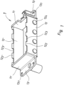
- the Fig. 1 shows a base frame 1.
- This base frame 1 is essentially rectangular in cross-section, i.e. it has two parallel, opposite end faces 11, 11' and, at right angles to this, two parallel, opposite side parts 12, 12', the two end faces 11, 11' being shorter than the two side parts 12, 12'.
- Both the end faces 11, 11' and the side parts 12, 12' have an essentially rectangular shape, with a flange 13, 13' projecting at right angles to the end faces 11, 11' being formed onto each of them, each of these two flanges 13, 13' having two screw holes 131, 131', so that the base frame 1 has a total of four screw holes 131, 131'.
- the two side parts 12, 12' each have a plurality of webs 122, 122' arranged symmetrically opposite one another on a first edge.
- the term "short" in this context means that the length of the webs 122, 122' extending upwards in the drawing is less than their width.
- the webs 122, 122' could also be significantly longer in a slightly different embodiment. For example, their length could correspond to or even exceed their width. Open recesses 123, 123' are thus formed between these webs 122, 122'.
- each side panel 2, 2' four such open recesses 123, 123' are provided on each side panel 2, 2', but a different number of recesses would of course also be conceivable, for example, three, five, six, seven, or eight.
- the number of open recesses 132, 132' in each side panel 12, 12' corresponds to the number of modules 3 that the corresponding support frame is capable of accommodating.
- each side part 12, 12' has several fastening pins 124, 124' for fastening the corresponding cheek part 2, 2'.
- the fastening pins 124, 124' have a circular cross-section; however, any other shape would also be conceivable; for example, the fastening pins 124, 124' could also be oval, rectangular, square, triangular, pentagonal, n-sided, or any other flat shape.
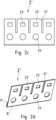
- two cheek parts 2, 2' are provided for the holding frame, namely a first cheek part 2 and a second cheek part 2'.
- Fig. 2 a and Fig. 2c show each of these cheek parts 2, 2' in a first perspective, in which the viewing direction is perpendicular to it.
- Fig. 2b and Fig. 2d show the respective cheek part 2, 2' from an oblique view.
- Each cheek part 2, 2' which in the present embodiment is preferably a stamped and bent part, has three slots 21, 21', through which four equally sized tabs 22, 22' are formed.
- the number of tabs 22, 22' of the respective cheek part 2, 2' corresponds to the number of open recesses 123, 123' on each of the two side parts 12, 12' of the base frame 1.
- a locking window 23, 23' is provided in each tab 22, 22' of each cheek part 2, 2'.
- the locking windows 23 of the first cheek part 2 are larger than the locking windows 23' of the second cheek part 2'.
- the two cheek parts 2, 2' thus differ from one another in the size of their locking windows 23, 23'.
- additional fastening recesses 24, 24' are provided in the cheek parts 2, 2', which in the present embodiment have a circular shape, but could of course also have any other shape, for example, oval, rectangular, square, triangular, pentagonal, n-sided or any other flat shape.
- the fastening pins 124, 124' of the base frame 1 fit snugly into the respective fastening recesses 24, 24' of the corresponding side panels 2, 2', so that the respective side panel 2, 2' can be plugged onto the corresponding side panel 12, 12'. Additionally, the respective side panel 2, 2' can be attached to the corresponding side panel 12, 12' on another side, for example by gluing, welding, soldering, riveting, and/or screwing.
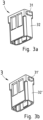
- Fig. 3 a and the Fig. 3b show a module 3 that can be inserted into the support frame in two different views.
- Fig. 3 a and the Fig. 3b show a module 3 that can be inserted into the support frame in two different views.
- other modules with a similar design can also be used.
- the module 3 has a first locking lug 31 on a first longitudinal side 32, which is designed to lock into a locking window 23 of the first cheek part 2.
- a second longitudinal side 32' opposite this first longitudinal side 32 the module 3 has a second locking lug 31', which is narrower than the first locking lug and is designed to lock into a locking window 23' of the second cheek part 2'.
- the module is very compact, which improves its heat resistance.
- the orientation of module 3 in the holding frame is determined by the shape of the locking lugs 31, 31' and the shape of the windows 23, 23'.
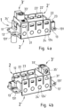
- the Fig. 4 shows a fully assembled support frame in which the two cheek parts 2, 2' are attached to the base frame.
- the fastening pins 124, 124' of the base frame engage in the fastening recesses 24, 24' of the corresponding cheek parts 2, 2'.
- this fastening is particularly stable because the lower edge K, K' of the respective sheet metal of the cheek part 2, 2' directly adjoins the corresponding side part 12, 12' of the base frame 1.
- the cheek parts 2, 2' can also be soldered, welded, screwed, riveted, or otherwise attached to the base frame 1.
- the cheek parts 2, 2' have a higher elasticity than the base frame 1, in particular in the area of their tabs 22, 22'.
- the base frame 1 therefore has greater rigidity than the cheek parts 2, 2'. Conversely, the cheek parts 2, 2' have greater elasticity than the base frame.
- the support frame is fixed at four corner points.
- it can be fixed by screwing to the four screw holes 131, 131' of its flanges 13, 13' in or to a metallic connector housing.
- this tab 22 is reversibly deflected, for example, by a distance of at least 0.2 mm, preferably of at least 0.4 mm, in particular of at least 0.8 mm, i.e., for example, by more than 1.6 mm.
- the base frame 1 is even deflected in this area in which its When stiffness is still at its lowest, the deflection is only by a distance of less than 0.2 mm, preferably less than 0.1 mm, in particular less than 0.05 mm, i.e., for example, less than 0.025 mm.
- the base frame 1 is stiffer than the cheek parts 2, 2'.
- the base frame 1 is to be regarded as stiff, and the cheek parts 2, 2' are each to be described as spring-elastic.
- the cheek part 2 is spring-elastic, and the elasticity of the cheek part 2 is selected, in particular according to the values specified above, so that the modules 3 can be inserted and removed manually.
- the base frame 1 is rigid, and, in particular, the rigidity of the base frame 1 is so high, in particular according to the values specified above, that the inserted modules 3 are held therein with sufficient strength to ensure the intended function of an associated connector.
- the modules 3, and thus also the contacts present in the modules 3, are positioned geometrically precisely and mechanically stable enough to reliably make electrical contact with corresponding mating contacts of a comparable mating connector.
- Such a connector and a corresponding mating connector can additionally have a preferably metallic housing into which a holding frame fully or partially equipped with modules 3 is inserted.
- FIG. 4 a and Fig. 4b A specially designed PE module 3' is held in the holding frame shown, which in its basic form is similar to Fig. 3a , b.
- the PE module 3' has an electrically conductive PE contact 33', which is electrically connected via the PE module 3' to an electrically conductive earthing clamp 34' that also belongs to the PE module 3'.
- the PE contact 33' can, for example, be a screw contact, i.e. the PE contact 33' has an earthing screw 35' that is suitable for conductively connecting an earthing cable to the PE contact 33' and mechanically fixing it thereto.
- This earthing cable is electrically connected to the base frame 1 by the PE module 3' via its earthing clamp 34', which is clamped to one of the end faces 11' of the holding frame.
- the holding frame can have such a PE contact, for example, a PE screw contact, on its base frame 1 itself.
- the PE contact can, for example, be molded onto the base frame 1. This can be done during the production of the base frame 1, for example, using an injection molding process.
- the holding frame serves to accommodate similar and/or different modules 3.
- the holding frame can be made of at least two different materials, at least one of which is electrically conductive.
- the holding frame has at least partially resilient properties.
- the holding frame can be made partly of a rigid material and partly of a resilient material.
- the support frame can be designed in multiple parts.
- the support frame can consist of at least two parts, of which a first part is made of a first material and a second part is made of a second material, wherein the elastic modulus of the first material is greater than the elastic modulus of the second material.
- the first part is designed as a base frame 1 and the second part is designed as two cheek parts 2, 2'.
- the base frame 1 can have a rectangular cross-section and two side parts 12, 12' arranged parallel to one another and two end faces 11, 11' arranged perpendicularly thereto and parallel to one another.
- the base frame 1 can be rigid.
- the base frame 1 can be constructed in one piece.
- the base frame 1 can be designed as a die-cast part.
- Each cheek part 2, 2' can be resilient.
- Each cheek part 2, 2' can be electrically conductive and can also be made of resilient sheet metal.
- Each cheek part 2, 2' can be attached to the base frame 1, for example by gluing, welding, soldering, riveting, locking, and/or screwing.
- Each cheek part 2, 2' has a plurality of slots 21, 21 through which tabs 22, 22' are formed in the respective cheek part 2, 2'.
- the width of the tabs 22, 22' can correspond to the width of the modules 3. In particular, all tabs 22, 22' can have the same width.
- Each tab 22, 22' has a locking means consisting of a locking window 23, 23' arranged in the respective tab 22, 22'.
- Each cheek part 2, 2' can, in particular, be a stamped and bent part.
- the holding frame can have a protective earthing contact (PE contact) or at least be equipped with one.
- the holding frame which is intended for a connector and is suitable for receiving similar and/or different modules 3, is formed from at least two different materials.
- At least a first part of the holding frame namely a base frame 1
- Each cheek part 2, 2' can be punched out of a spring-elastic sheet and in particular folded by 180° at at least one bending edge B, B'.
- Each cheek part 2, 2' can be attached to the base frame 1 in particular by gluing, welding, soldering, riveting, locking and/or screwing.
- the holding frame can hold a module 3 accommodated therein in one direction with its base frame and at the same time fix this module 3 perpendicularly thereto with tabs 13, 13', 23, 23' belonging to the respective cheek part 2, 2', in particular by locking the module 3 to its tabs 22, 22'.
Landscapes
- Engineering & Computer Science (AREA)
- Manufacturing & Machinery (AREA)
- Connector Housings Or Holding Contact Members (AREA)
- Casings For Electric Apparatus (AREA)
- Manufacturing Of Electrical Connectors (AREA)
- Absorbent Articles And Supports Therefor (AREA)
Description
- Die Erfindung betrifft einen Halterahmen gemäß dem Oberbegriff des unabhängigen Hauptanspruchs 1.
- Weiterhin betrifft die Erfindung ein Verfahren gemäß dem Oberbegriff des unabhängigen Nebenanspruchs 6 und ein Verfahren gemäß dem Oberbergriff des unabhängigen Nebenanspruchs 13.
- Derartige Halterahmen werden benötigt, um mehrere zueinander gleichartige und/oder auch unterschiedliche Module aufzunehmen. Bei diesen Modulen kann es sich beispielsweise um Isolierkörper handeln, die als Kontaktträger für elektronische und elektrische und möglicherweise auch für optische und/oder pneumatische Kontakte vorgesehen sind. Von besonderer Wichtigkeit ist es, dass der Halterahmen eine vorschriftsmäßigen Schutzerdung gemäß der Steckverbinder-Norm EN61984 beispielsweise zum Einfügen des mit Modulen bestückten Halterahmens in metallische Steckverbindergehäuse, ermöglicht.
-
DE 2736079 A1 bezieht sich auf die Befestigung von Reihenklemmen oder Anschlußmoduln aus starrem Isoliermaterial durch Einrasten und Befestigen an ihrem Platz auf einer metallischen Trägerschiene, die unsymmetrisch sein kann und die durch ein U-förmiges Profil mit zwei nach innen vorspringenden Vorsprüngen gebildet sein kann, die in ihrer Höhe gegeneinander und gegenüber dem mittleren Teil des U-förmigen Profils versetzt sein können. - Insbesondere offenbart
DE 2736079 A1 eine einrastbare Reihenklemme oder ein Verbindungsmodul für elektrische Leitungen, wobei die Reihenklemme an ihren beiden Endkanten, die parallel zur Längsrichtung einer Trägerschiene verlaufen, zum Zusammenbau derartiger Reihenklemmen mit Nuten versehen ist, die jeweils mit innen liegenden horizontalen Vorsprüngen zusammenwirken, die in der Nähe der freien Enden der beiden Schenkel eines metallischen U-förmigen Trägerprofils vorgesehen sind, wobei die Nuten in jeweils unterschiedlichen Abständen von dem Boden des Profils gegen die Wirkung von zumindest einer quer verlaufenden Blattfeder eingesetzt werden können, die zwei Teile aufweist, die in Richtung auf den Boden bzw. gegen den hinteren Schenkel des Profils zusammendrückbar sind und von der ein freies Ende sich in Querrichtung im Inneren einer Nut verschieben kann, die in der Stärke des Metalls des Profils parallel zu dem Boden am Verbindungspunkt dieses Bodens mit einem inneren Teil mit vergrößerter Stärke des vorderen Schenkels dieses Profils ausgebildet ist, daß die Tiefe dieser Nut bezüglich des Abstandes zwischen den inneren Vorsprüngen ausreicht, um die Zusammendrückung des gekrümmten mittleren Teils der querverlaufenden Blattfedern zu ermöglichen, die erforderlich ist, damit die nach innen vorspringenden Vorsprünge in das Innere der Nuten der Endflächen der Reihenklemmen eintreten können, und daß der untere Teil der vorderen Endkante der Reihenklemmen eine Abschrägung aufweist, die das Einrasten dieser Reihenklemmen erleichtert und das Einrasten durch einfache Druckausübung auf die Reihenklemmen in Richtung auf den Boden des Profils der Trägerschiene ermöglicht. -
DE 295 080 95 U1 betrifft einen Moduleinsetzrahmen zur Aufnahme von Kontaktmodulen zum Einsetzen in Steckerverbindergehäuse mit einem Rahmenkörper aus zwei Wangenteilen und zwei Kopfstücken, die sich jeweils parallel gegenüberliegen und eine Aufnahmeöffnung für die Kontaktmodule bilden, mit Haltemitteln an den Wangenteilen, von denen die Kontaktmodule fixiert und gehalten werden, mit Führungsmitteln an den Kopfstücken, die einerseits ein positiv/männliches Führungselement und andererseits ein negativ/weibliches Führungselment umfassen, und mit Schutzkontaktmitteln, die an den Kopfstücken ausgebildet sind, wobei die Schutzkontaktmittel durch eines der Führungselemente selber, das einstückig mit dem Rahmenkörper verbunden ist, und eine einzelne Schutzkontaktfeder, die am anderen der Führungselemente befestigt ist, gebildet werden. - Aus der Druckschrift
EP 0 860 906 B1 ist ein Halterahmen zur Halterung von Steckverbindermodulen und zum Einbau in Steckverbindergehäuse bzw. zum Anschrauben an Wandflächen bekannt, wobei die Steckverbindermodule in den Halterahmen eingesetzt sind und Halterungsmittel an den Steckverbindermodulen mit an gegenüberliegenden Wandteilen (Seitenteilen) des Halterahmens vorgesehenen Ausnehmungen zusammenwirken, wobei die Ausnehmungen als allseitig geschlossene Öffnungen in den Seitenteilen des Halterahmens ausgebildet sind, wobei der Halterahmen aus zwei gelenkig miteinander verbundenen Hälften besteht, wobei die Trennung des Halterahmens quer zu den Seitenteilen des Rahmens vorgesehen ist, und wobei Gelenke in den Befestigungsenden des Halterahmens derart angeordnet sind, dass beim Aufschrauben des Halterahmens auf eine Befestigungsfläche sich die Rahmenteile derart ausrichten, dass die Seitenteile des Halterahmens rechtwinklig zur Befestigungsfläche ausgerichtet sind und die Steckverbindermodule über die Halterungsmittel eine formschlüssige Verbindung mit dem Halterahmen aufweisen. In der Praxis sind solche Halterahmen üblicherweise in einem Druckgussverfahren, insbesondere in einem Zinkdruckgussverfahren gefertigt. - Die Druckschrift
EP 2 581 991 A1 offenbart einen Halterahmen für Steckverbindermodule, der zwei Rahmenhälften aufweist, die durch Linearverschieben der einen Rahmenhälfte relativ zur anderen Rahmenhälfte in eine Schieberichtung miteinander verrastbar sind, wobei an den Rahmenhälften jeweils zueinander korrespondierende Rastmittel vorgesehen sind, die beim Linearverschieben ein Verrasten der beiden Rahmenhälften miteinander in zwei verschiedene Raststellungen bewirken, in denen die Rahmenhälften in verschiedenem Abstand zueinander beabstandet sind. - Es hat sich in der Praxis jedoch gezeigt, dass solche Halterahmen bei der Montage eine aufwändige Bedienung erfordern. Beispielsweise müssen solche Halterahmen aus dem Steckverbinder herausgeschraubt und/oder entrastet werden, sobald auch nur ein einziges Modul ausgetauscht werden soll. Dabei fallen möglicherweise auch die anderen Module, deren Entnahme gar nicht erwünscht war, aus dem Halterahmen heraus und müssen dann vor dem Zusammenschrauben und/oder vor dem Verrasten der Rahmenhälften wieder eingefügt werden. Schließlich müssen sich bereits vor dem Zusammenfügen der Rahmenhälften alle Module gleichzeitig in der für sie vorgesehenen Position befinden, um beim Zusammenfügen der Rahmenhälften endgültig im Halterahmen fixiert zu werden, was die Montage erschwert.
- Die Druckschrift
EP 1 801 927 B1 offenbart einen Halterahmen, der aus einem einteiligen Kunststoffspritzteil besteht. Der Halterahmen ist als umlaufender Kragen ausgebildet und weist an seiner Steckseite mehrere durch Schlitze getrennte Wandsegmente auf. Jeweils zwei gegenüber liegende Wandsegmente bilden einen Einfügebereich für ein Steckermodul, wobei die Wandsegmente fensterartige Öffnungen aufweisen, die zur Aufnahme von an den Schmalseiten der Module angeformten Vorsprüngen dienen. Weiterhin ist in den Wandsegmenten jeweils eine Führungsnut vorgesehen. Die Führungsnut ist oberhalb der Öffnungen mittels eines nach außen versetzten Fenstersteges gebildet, der auf der Innenseite eine Einführungsschräge aufweist. Zusätzlich weisen die Steckmodule Rastarme auf, die an den Schmalseiten in Richtung der Kabelanschlüsse wirkend, angeformt sind, und unterhalb der seitlichen Kragenwand verrasten, so dass zwei unabhängige Rastmittel die Steckverbindermodule im Halterahmen fixieren. - Nachteilig bei diesem Stand der Technik ist zum einen, dass es sich um einen aus Kunststoff gebildeten Halterahmen handelt, der gattungsgemäß nicht zur Schutzerdung und damit nicht für den Einbau in metallische Steckverbindergehäuse geeignet ist. Die Verwendung metallischer Steckverbindergehäuse setzt eine solche Schutzerdung jedoch voraus und ist sowohl wegen ihrer mechanischen Robustheit, ihrer Temperaturbeständigkeit und wegen ihrer elektrisch schirmenden Eigenschaften in vielen Fällen notwendig und daher vom Kunden erwünscht. Weiterhin hat sich gezeigt, dass die Herstellung der vorgenannten Kunststoffhalterahmen im Spritzgussverfahren zumindest schwierig und nur mit hohem Aufwand zu realisieren ist. Letztlich ist auch die Hitzebeständigkeit eines solchen Kunststoffhalterahmens für spezielle Anwendungen, beispielsweise in der Nähe eines Hochofens, nicht immer ausreichend. Schließlich werden das Kunststoffmaterial und die Form, insbesondere die Stärke des Halterahmens, an den relevanten Stellen primär von den Anforderungen an die Biegsamkeit bestimmt und nicht von denen der Temperaturbeständigkeit.
- Die Aufgabe der Erfindung besteht darin, eine Bauform für einen Halterahmen anzugeben, die einerseits eine gute Hitzebeständigkeit und eine hohe mechanische Robustheit aufweist und die insbesondere auch beim Einbau in ein metallisches Steckverbindergehäuse eine entsprechende Schutzerdung, insbesondere eine PE ("Protection Earth"), ermöglicht und die andererseits auch eine komfortable Bedienbarkeit, insbesondere beim Auswechseln einzelner Module, gewährleistet.
- Diese Aufgabe wird in einem ersten Aspekt mit einem Halterahmen der eingangs erwähnten Art durch die Merkmale des kennzeichnenden Teils des unabhängigen Hauptanspruchs 1 gelöst.
- In weiteren Aspekten wird die Aufgabe mit einem Verfahren der eingangs erwähnten Art durch die Merkmale des kennzeichnenden Teils der unabhängigen Nebenansprüche 6 und 13 gelöst.
- Ein solcher Halterahmen ist im Bereich der schweren Industriesteckverbinder einsetzbar und kann zumindest teilweise aus einem elektrisch leitfähigen Material bestehen. Dadurch wird gegebenenfalls eine Schutzerdung ermöglicht, die beispielsweise dadurch realisiert sein kann, dass der Halterahmen einen PE-Kontakt aufweist oder zumindest mit einem solchen PE-Kontakt ausgestattet ist.
- Der Halterahmen weist einen Grundabschnitt und einen Verformungsabschnitt auf, die wenigstens teilweise aus unterschiedlichen Werkstoffen gebildet sind. Der Grundabschnitt dient zur Fixierung eines aufgenommenen Moduls in einer Ebene. Der Verformungsabschnitt kann einen Einführzustand und einen Haltezustand annehmen, wobei der Einführzustand ein Einführen wenigstens eines Moduls in einer Richtung quer zur Ebene in den Halterahmen erlaubt, wobei ein aufgenommenes Modul im Haltezustand fixiert ist.
- Der Halterahmen weist einen Grundrahmen als Grundabschnitt und zwei Wangenteile als Verformungsabschnitt auf. Der Grundrahmen kann dann aus einem anderen Werkstoff gebildet sein als die Wangenteile und somit vorteilhafterweise eine geringere Elastizität und damit eine größere Steifigkeit besitzen als die Wangenteile.
- Die Wangenteile können aus einem Material gebildet sein, das entsprechend seinem Spannungs/Dehnungs-Diagramm elastischer ist, also ein kleineres Elastizitätsmodul aufweist, als dasjenige Material, aus dem der Grundabschnitt, insbesondere der Grundrahmen, gebildet ist. Umgekehrt formuliert kann das Material des Grundabschnitts steifer sein als das Material, aus dem der Verformungsabschnitt gebildet ist. Beispielsweise kann das Material des Grundrahmens entsprechend seinem Spannungs/Dehnungs-Diagramm ein Elastizitätsmodul besitzen, welches größer ist als das Elastizitätsmodul desjenigen Materials, aus dem die Wangenteile gebildet sind.
- Der Betrag des Elastizitätsmoduls ist dabei umso größer, je mehr Widerstand ein Material seiner elastischen Verformung entgegensetzt.
- Weiterhin kann das Material, aus dem der Verformungsabschnitt gebildet ist, entsprechend seinem Spannungs/Dehnungs-Diagramm, einen größeren elastischen Bereich besitzen, als dasjenige Material, aus dem der Grundabschnitt gebildet ist.
- Insbesondere kann der Grundabschnitt, insbesondere der Grundrahmen, steif, insbesondere idealisiert betrachtet starr, ausgeführt sein.
- Weiterhin können die Wangenteile federelastisch ausgeführt sein und können vorteilhafterweise aus einem federelastischen Blech gefertigt sein.
- Unter einem federelastischen Blech ist dabei ein Blech zu verstehen, das federelastische Eigenschaften, wie beispielsweise eine reversible Verformbarkeit, insbesondere unter Aufbringung einer entsprechenden Rückstellkraft, aufweist, also beispielsweise ein Blech, das aus Federstahl oder einem vergleichbaren Material gefertigt ist.
- Vorteilhafte Ausgestaltungen der Erfindung sind in den Unteransprüchen angegeben.
- Ein Vorteil der Erfindung besteht somit darin, dass die Module einzeln und mit nur sehr geringem Aufwand in den Halterahmen eingefügt und wieder daraus entfernt werden können, was insbesondere die händische Bestückung erleichtert. Die federelastischen Eigenschaften der Wangenteile gestatten es nämlich, Module einzeln mit nur sehr geringem Aufwand einzufügen oder zu entnehmen. Gleichzeitig kann der Grundrahmen durch seine Steifigkeit für die notwendige mechanische Stabilität beim Halten der eingefügten Module sorgen.
- Vorteilhafterweise ist sowohl für den Grundabschnitt, insbesondere den Grundrahmen, als auch für den Verformungsabschnitt, insbesondere die Wangenteile, durch eine Verwendung eines oder mehrerer metallischer Werkstoffe eine, verglichen beispielsweise mit Kunststoff, hohe Temperaturbeständigkeit und weiterhin auch eine besonders große mechanische Robustheit des Halterahmens gewährleistet.
- Ein weiterer Vorteil des Einsatzes eines oder mehrerer metallischer Werkstoffe besteht darin, dass der Halterahmen zur elektrischen Sicherheit eine Schutzerdung, insbesondere eine PE-Schutzerdung eines metallischen Steckverbindergehäuses, in welches der Halterahmen eingefügt wird, ermöglicht. Dies gewährleistet weiterhin als zusätzlichen Vorteil auch eine Schirmung der durch den Steckverbinder übertragenen Signale. Bei dieser Schirmung kann es sich um einen Schutz gegen Störfelder von außen handeln. Es kann sich aber auch um eine Schirmung zur Vermeidung oder Verminderung einer Störaussendung, also zum Schutz der Umwelt gegen Störfelder des Steckverbinders handeln. Mit anderen Worten werden nicht nur die durch die Module übertragenen Signale vor äußeren Störfeldern geschützt, sondern es findet auch ein Schutz der Umgebung vor Störungen statt, welche durch einen Stromfluss, der durch die Module verläuft, entstehen.
- Ein besonders großer zusätzlicher Vorteil der Verwendung eines oder mehrerer metallischer Werkstoffe besteht weiterhin darin, dass der Halterahmen einerseits besonders hitzebeständig ist und andererseits trotzdem, beispielsweise durch die Verwendung von federelastischem Blech, an den dafür erforderlichen Stellen eine ausreichend hohe Elastizität aufweist, um die Module einzeln und mit geringem Aufwand in den Modulrahmen einzufügen und wieder zu entnehmen. Daher ist es von besonders großem Vorteil, wenn der Halterahmen an geeigneten Stellen federelastisches Blech aufweist, denn dadurch ist er bei mindestens ebenso großer Elastizität wesentlich hitzebeständiger als ein aus mechanischer Sicht sonst funktional vergleichbarer Kunststoffrahmen. Dazugehörige Module können in ihrer Bauform dementsprechend kompakt ausgeführt sein, so dass sie weiterhin aus Kunststoff gefertigt sein können und trotzdem verhältnismäßig hitzebeständig sind.
- Besonders vorteilhaft ist es, wenn der Halterahmen mehrere verschiedene Bereiche, beispielsweise einen ersten und einen zweiten Bereich, aufweist, welche zueinander eine unterschiedliche Elastizität besitzen, weil er dann im Bereich der höchsten Biegebeanspruchung gezielt ein höheres Widerstandsmoment aufbringen kann. Der erste Bereich kann dem Grundabschnitt entsprechen. Der zweite Bereich kann dem Verformungsabschnitt entsprechen.
- Diese verschiedenen Bereiche, insbesondere der Grundabschnitt und der Verformungsabschnitt, können beispielsweise aus verschiedenen Materialien gebildet sein und so bevorzugt verschiedene Materialeigenschaften, insbesondere verschiedene Elastizitätsmodule, aufweisen.
- Der zweite Bereich, insbesondere der Verformungsabschnitt, kann dadurch eine höhere Elastizität aufweisen, als der erste Bereich, der insbesondere dem Grundabschnitt entspricht. Der erste Bereich kann somit, umgekehrt formuliert, eine größere Steifigkeit besitzen als der zweite Bereich. Insbesondere kann der erste Bereich steif ausgebildet sein und der zweite Bereich kann federelastisch ausgebildet sein. Eine solche Elastizität bzw. Steifigkeit kann einerseits, wie bereits erwähnt, durch das jeweils verwendete Material erreicht werden und/oder es kann andererseits auch durch die geometrische Formgebung dieser Bereiche, insbesondere des Grundabschnitts und des Verformungsabschnitts, erreicht werden.
- Der erste Bereich, insbesondere der Grundabschnitt, kann dazu aus einem steifen Material gebildet sein, beispielswiese aus einer Zinklegierung oder aus einer Aluminiumlegierung oder aus einer Kupferlegierung. Der zweite Bereich, insbesondere der Verformungsabschnitt, kann aus einem federelastischen Material gebildet sein und somit beispielsweise aus einem federelastischen Stahlblech bestehen.
- Der erste Bereich, insbesondere der Grundabschnitt, kann in einem Gießverfahren, beispielsweise in einem Zinkdruckguss- oder Aluminiumdruckgussverfahren hergestellt werden oder auch durch Fräsen aus beispielsweise einer Kupferlegierung hergestellt werden. Beispielsweise kann es sich bei dem ersten Bereich, insbesondere dem Grundabschnitt, bevorzugt um den umlaufenden Grundrahmen handelt. Bei dem Grundrahmen kann somit insbesondere um ein Zinkdruckgussteil handeln. Der Grundrahmen kann im Querschnitt im Wesentlichen rechteckig ausgebildet sein, besitzt also zwei einander parallel gegenüber liegende Stirnflächen und rechtwinklig dazu zwei einander parallel gegenüber liegende Seitenteile, wobei die beiden Stirnflächen kürzer sind als die beiden Seitenteile. Sowohl die Stirnflächen als auch die Seitenteile können dabei eine im Wesentlichen rechteckige Form aufweisen.
- Weiterhin kann der zweite Bereich, insbesondere der Verformungsabschnitt mit den beiden, separaten Wangenteilen gebildet sein, von denen jedes Wangenteil bevorzugt aus jeweils einem federelastischen Blechteil besteht. Die beiden Wangenteile können gegebenenfalls aus demselben Material, insbesondere aus federelastischem Blech, bestehen und zudem die gleiche Stärke aufweisen. Beispielsweise können die bevorzugt beiden Wangenteile aus demselben Stanzblech ausgestanzt sein.
- Jedes Wangenteil kann im Wesentlichen flächig ausgebildet sein und bevorzugt eine rechteckige Grundform aufweisen. Somit besitzt es zwei einander gegenüber liegende, lange Kanten, nämlich eine erste und eine zweite Kante, und rechtwinklig dazu zwei einander gegenüberliegende kurze Kanten, nämlich eine dritte und eine vierte Kante. Das Wangenteil besitzt insbesondere in regelmäßigen Abständen an seiner ersten Kante beginnende und sich bevorzugt rechtwinklig dazu in Richtung der zweiten Kante in das Wangenteil hinein verlaufende, bevorzugt geradlinige, Schlitze, wodurch im Wangenteil frei stehende Laschen gebildet sind. Weiterhin ist in jeder dieser Laschen ein Rastfenster als Rastelement angeordnet. Diese Rastfenster sind dafür vorgesehen, Rastnasen eingefügter Module aufzunehmen, um die Module im Halterahmen zu verrasten. Weiterhin kann jedes Wangenteil mehrere Befestigungselemente, insbesondere Befestigungsausnehmungen in bevorzugt runder Form, zur Befestigung am Grundrahmen aufweisen.
- Jedes der beiden Wangenteile kann vorteilhafterweise an jeweils einer Außenseite eines der beiden Seitenteile am Grundrahmen befestigt sein, so dass sich jeweils zwei federelastische Laschen der beiden Wangenteile symmetrisch gegenüber stehen. Weiterhin können diese Laschen zu ihrem Ende hin leicht nach außen, d.h. vom Grundrahmen und somit voneinander weg, gebogen sein, um das Einfügen eines Moduls zu erleichtern.
- An dem entsprechenden Seitenteil, bevorzugt an beiden Seitenteilen, kann der Grundrahmen Befestigungsmittel, beispielsweise runde Befestigungszapfen, aufweisen. Diese Befestigungsmittel können in die Befestigungsausnehmungen des dazugehörigen Wangenteils eingreifen und die Wangenteile so, beispielsweise durch Verrasten und/oder durch eine form- und kraftschlüssige Verbindung am Grundrahmen halten. Zusätzlich oder alternativ dazu können die Wangenteile am Grundrahmen durch Verkleben, Schweißen, Löten, Nieten und/oder Verschrauben oder durch irgendeine andere Befestigungsart am Grundrahmen befestigt sein.
- Die dazu gehörenden Module können im Wesentlichen quaderförmig ausgebildet sein und können an zwei einander gegenüberliegenden Stirnflächen jeweils eine Breite aufweisen, die der Breite einer Lasche entspricht. Jedes Modul weist vorteilhafterweise an seinen beiden Stirnflächen jeweils eine Rastnase auf, die ebenfalls im Wesentlichen quaderförmig ausgeführt sein kann. Jede der federelastischen Laschen des Halterahmens besitzt vorteilhafterweise ein Rastfenster, welches im Wesentlichen rechteckig ausgebildet sein kann, und das zur bevorzugt formschlüssigen Aufnahme einer solchen Rastnase vorgesehen ist.
- Die beiden Rastnasen eines Moduls können sich, beispielsweise in ihrer Form und/oder ihrer Größe, insbesondere durch ihre Länge, voneinander unterscheiden und die Laschen an beiden Seiten des Halterahmens können dazu entsprechende Fenster aufweisen, die sich also ebenfalls voneinander unterscheiden und die in ihrer Größe und/oder ihrer Form zu jeweils einer der Rastnasen passen. Dies hat den Vorteil, dass dadurch die Orientierung jedes Moduls im Halterahmen festgelegt ist. Mit anderen Worten können die Rastfenster und die Rastnasen durch ihre Form und/ oder Größe als Kodiermittel, insbesondere als Polarisationsmittel, zur Orientierung der Module im Halterahmen verwendet werden.
- Vorteilhafterweise sind die Laschen des Halterahmens in einem frei stehenden Endbereich leicht vom Halterahmen weggebogen, was das Einführen der Module vereinfacht. Das Einführen eines Moduls in den Halterahmen gestaltet sich dann besonders bedienungsfreundlich. Dazu wird ein Modul nämlich zunächst zwischen zwei Laschen eines Halterahmens eingeführt und gleitet dann mit seinen beiden Stirnflächen und insbesondere mit den daran angeformten Rastnasen an den voneinander weggebogenen Endbereichen der Laschen entlang. Dadurch biegen sich die beiden Laschen kurzzeitig auseinander, bis die jeweiligen Rastnasen von dem dazugehörigen Rastfenster der jeweiligen Lasche aufgenommen werden und somit darin verrasten. Bei der Aufnahme der Rastnasen in das jeweilige Rastfenster federn die Laschen bevorzugt in ihre Ausgangsposition zurück. Auf diese Weise können die Module einzeln im Halterahmen verrasten.
- Gleichzeitig ist das Modul fest im bevorzugt steifen Grundrahmen gehalten. Um die Module wieder zu entrasten, müssen lediglich die beiden dazugehörigen Laschen wieder voneinander weggebogen werden. Daraufhin kann das jeweilige Modul einzeln aus dem Halterahmen entnommen werden, während die anderen Module weiterhin verrastet sind. Somit ist auf diese Weise ein fester Halt des Moduls im Halterahmen bei einer vergleichsweise geringen Betätigungskraft gewährleistet, was für die Bedienbarkeit besonders vorteilhaft ist.
- Von besonderem Vorteil ist es weiterhin, dass die Module bereits durch die vorgenannte Konstruktion mit ausreichender Haltekraft im Halterahmen gehalten sind und dementsprechend außer ihren Rastnasen keine weiteren Rastmittel, beispielswiese Rastarme, benötigen, denn dies vereinfacht ihre Bauform und damit ihren Herstellungsaufwand erheblich und sorgt gleichzeitig für eine kompakte Bauform und damit auch für eine hohe Hitzebeständigkeit der Module und damit des gesamten Steckverbinders.
- In einer Ausführungsform ist es besonders vorteilhaft, wenn diese beiden Wangenteile gleichartig sind, d.h. es müssen trotz der zweiteiligen Ausführung des Halterahmens nur Wangenteile einer Art hergestellt werden, was den Herstellungsaufwand weiterhin verringert.
- In einer anderen bevorzugten Ausgestaltung unterscheiden sich die beiden Wangenteile durch die Größe und/oder die Form ihrer Rastfenster. Dies hat den Vorteil, dass dadurch die Orientierung jedes Moduls, das dementsprechend auch zwei verschiedene Rastnasen aufweist, festgelegt ist. Mit anderen Worten können die Rastfenster und die Rastnasen somit durch ihre Form als Kodiermittel zur Orientierung der Module dienen.
- Zur Schutzerdung (PE) kann der Halterahmen mit einem entsprechenden PE-Modul bestückt sein, welches beispielsweise über eine elektrisch leitfähige Erdungsklammer einen elektrischen Kontakt zwischen einem daran angeschlossenen Erdungskabel und dem zumindest teilweise elektrisch leitfähigen, insbesondere metallischen, Halterahmen herstellt. Dadurch kann der Halterahmen mit einem PE-Kontakt bestückt werden.
- Alternativ dazu kann der Halterahmen selbst einen PE-Kontakt, beispielsweise einen Schraubkontakt, für das Erdungskabel besitzen. Beispielsweise kann ein solcher PE-Kontakt an den Grundrahmen angeformt sein.
- Ein Ausführungsbeispiel der Erfindung ist in der Zeichnung dargestellt und wird im Folgenden näher erläutert. Es zeigen:
- Fig. 1
- einen Grundrahmen;
- Fig. 2 a,b
- ein erstes Wangenteil aus zwei verschiedenen Perspektiven;
- Fig. 2 c,d
- ein zweites Wangenteil aus zwei verschiedenen Perspektiven;
- Fig. 3 a,b
- ein Modul aus zwei verschiedenen Perspektiven;
- Fig. 4 a,b
- einen Halterahmen mit einem eingefügten PE-Modul aus zwei verschiedenen Perspektiven.
- Die
Fig. 1 zeigt einen Grundrahmen 1. Dieser Grundrahmen 1 ist im Querschnitt im Wesentlichen rechteckig ausgebildet, besitzt also zwei einander parallel gegenüber liegende Stirnflächen 11, 11' und rechtwinklig dazu zwei einander parallel gegenüber liegende Seitenteile 12, 12', wobei die beiden Stirnflächen 11, 11' kürzer sind als die beiden Seitenteile 12, 12'. Sowohl die Stirnflächen 11, 11' als auch die Seitenteile 12, 12' weisen ihrerseits eine im Wesentlichen rechteckige Form auf, wobei an die Stirnflächen 11, 11' jeweils ein rechtwinklig dazu abstehender Flansch 13, 13' angeformt ist, wobei jeder dieser beiden Flansche 13,13'jeweils zwei Schraubbohrungen 131, 131' aufweist, so dass der Grundrahmen 1 insgesamt vier Schraubbohrungen 131, 131' besitzt. - Die beiden Seitenteile 12, 12' besitzen jeweils an einer ersten Kante mehrere, in der vorliegenden Ausführung relativ kurz ausgeführte einander symmetrisch gegenüberstehend angeordnete Stege 122, 122', wobei mit dem Begriff "kurz" in diesem Zusammenhang gemeint ist, dass die in der Zeichnung nach oben verlaufende Länge der Stege 122, 122' deren Breite unterschreitet. Die Stege 122, 122' könnten in einer etwas anderen Ausführung aber auch deutlich länger sein. Beispielsweise könnte ihre Länge ihrer Breite entsprechen oder diese gar noch überschreiten. Zwischen diesen Stegen 122, 122' sind somit offene Ausnehmungen 123, 123'gebildet.
- Im vorliegenden Beispiel sind an jedem Wangenteil 2, 2' vier solche offenen Ausnehmungen 123, 123' vorgesehen, aber es wäre selbstverständlich auch eine andere Zahl von Ausnehmungen denkbar, beispielsweise drei, fünf, sechs, sieben oder acht. Die Zahl der offenen Ausnehmungen 132, 132' in jedem Seitenteil 12, 12' entspricht der Anzahl von Modulen 3, die der entsprechende Halterahmen aufzunehmen in der Lage ist.
- Weiterhin weist jedes Seitenteil 12, 12' mehrere Befestigungszapfen 124, 124' zur Befestigung des dazugehörigen Wangenteils 2, 2' auf. Im vorliegenden Fall besitzen die Befestigungszapfen 124, 124' eine im Querschnitt kreisrunde Form; es wäre aber auch irgendeine andere Form denkbar; die Befestigungszapfen 124, 124' könnten also beispielsweise auch oval, rechteckig, quadratisch, dreieckig, fünfeckig, n-eckig oder in jeder anderen flächigen Form ausgebildet sein.
- Für den Halterahmen sind somit zwei Wangenteile 2, 2' vorgesehen, nämlich ein erstes Wangenteil 2 und ein zweites Wangenteil 2'.
- Die
Fig. 2 a undFig. 2c zeigen jeweils eines dieser Wangenteile 2, 2' in einer ersten Perspektive, bei der die Blickrichtung rechtwinklig dazu verläuft. DieFig. 2b undFig. 2d zeigen das jeweilige Wangenteil 2, 2' aus einer schrägen Ansicht. Jedes Wangenteil 2, 2', bei dem es sich im vorliegenden Ausführungsbeispiel bevorzugt um ein Stanzbiegeteil handelt, besitzt drei Schlitze 21, 21', durch welche vier gleichgroße Laschen 22, 22' gebildet sind. Die Zahl der Laschen 22, 22' des jeweiligen Wangenteils 2, 2' entspricht der Anzahl der offenen Ausnehmungen 123, 123' an jeweils einem der beiden Seitenteile 12, 12' des Grundrahmens 1. - In jeder Lasche 22, 22' jedes Wangenteils 2, 2' ist jeweils ein Rastfenster 23, 23' vorgesehen. Die Rastfenster 23 des ersten Wangenteils 2 sind größer als die Rastfenster 23' des zweiten Wangenteils 2'. Die beiden Wangenteile 2, 2' unterscheiden sich somit voneinander durch die Größe ihrer Rastfenster 23, 23'. Weiterhin sind in den Wangenteilen 2, 2' zusätzliche Befestigungsausnehmungen 24, 24' vorgesehen, die in dem vorliegenden Ausführungsbeispiel eine kreisrunde Form besitzen, aber selbstverständlich auch irgendeine andere Form besitzen könnten, also beispielsweise oval, rechteckig, quadratisch, dreieckig, fünfeckig, n-eckig oder in jeder anderen flächigen Form ausgebildet sein könnten.
- Die Befestigungszapfen 124, 124' des Grundrahmens 1 passen formschlüssig in die jeweiligen Befestigungsausnehmungen 24, 24' der dazugehörigen Wangenteile 2, 2', so dass das jeweilige Wangenteil 2, 2' auf das dazugehörige Seitenteil 12, 12' aufsteckbar ist. Zusätzlich kann das jeweilige Wangenteil 2, 2' noch anderseitig am entsprechenden Seitenteil 12, 12' befestigt werden, beispielsweise durch Verkleben, Schweißen, Löten, Nieten und/oder Verschrauben.
- In den
Fig. 2b und2d ist zu erkennen, dass das jeweilige Wangenteil 2, 2' im unteren Endbereich an einer Biegelinie B, B' um 180° gefaltet und damit in diesem Bereich verstärkt ist. Eine untere Kante K, K' des dazugehörigen Bleches kommt dabei zwischen den Befestigungsausnehmungen 24 und einer dazugehörigen Biegelinie B, B' zu liegen, so dass die Befestigungsausnehmungen 24, 24' unverdeckt sind und die Befestigungszapfen 124, 124' ungehindert darin eingeführt werden können. - Die
Fig. 3 a und dieFig. 3b zeigen ein in den Halterahmen einfügbares Modul 3 in einer möglichen Bauform aus zwei verschiedenen Ansichten. Selbstverständlich können auch andere Module in ähnlicher Bauform Verwendung finden. - Das Modul 3 besitzt an einer ersten Längsseite 32 eine erste Rastnase 31, die zum Verrasten in einem Rastfenster 23 des ersten Wangenteils 2 vorgesehen ist. An einer dieser ersten Längsseite 32 gegenüber liegenden zweiten Längsseite 32' besitzt das Modul 3 eine zweite Rastnase 31', die schmaler ist als die erste Rastnase, und die zum Verrasten in einem Rastfenster 23' des zweiten Wangenteils 2' vorgesehen ist. Weiterhin ist das Modul sehr kompakt ausgeführt, was seine Hitzebeständigkeit verbessert.
- Durch die Form der Rastnasen 31, 31' und die Form der Fenster 23, 23' ist die Orientierung des Moduls 3 im Halterahmen festgelegt.
- Die
Fig. 4 zeigt einen fertig montierten Halterahmen, bei dem also die beiden Wangenteile 2, 2' am Grundrahmen befestigt sind. Dabei greifen die Befestigungszapfen 124, 124' des Grundrahmens in die Befestigungsausnehmungen 24, 24' der entsprechenden Wangenteile 2, 2'. Zusätzlich dazu ist eine besondere Stabilität dieser Befestigung gegeben, indem die besagte untere Kante K, K' des jeweiligen Bleches des Wangenteils 2, 2' direkt mit dem entsprechenden Seitenteil 12, 12' des Grundrahmens 1 abschließt. Zusätzlich oder alternativ zur Befestigung durch die Befestigungszapfen 124, 124' und die Befestigungsausnehmungen 24, 24' können die Wangenteile 2, 2' auch mit dem Grundrahmen 1 verlötet, verschweißt, verschraubt, vernietet oder anderweitig daran befestigt sein. - Die Wangenteile 2, 2' besitzen insbesondere im Bereich ihrer Laschen 22, 22' eine höhere Elastizität als der Grundrahmen 1. Umgekehrt formuliert, besitzt der Grundrahmen 1, der in einem Druckgussverfahren, insbesondere einem Zinkdruckgussverfahren, hergestellt sein kann, eine größere Steifigkeit als die beiden federelastischen Wangenteile 2, 2', die beispielsweise aus federelastischem Stahlblech bestehen können.
- Dies bedeutet, dass eine bestimmte Kraft, von beispielsweise 10 N, die an einer beliebigen Lasche 22 eines Wangenteils 2 in Höhe dessen Rastfensters 23 rechtwinklig zur Fläche des Wangenteils 2, bezüglich des Halterahmens von innen nach außen gerichtet, angreift, eine, in Höhe ihres Rastfensters 23 zu messende Auslenkung der Lasche 22 bewirkt, welche größer ist, als diejenige Auslenkung, die der Grundrahmen 1 an einem beliebigen Punkt erfährt, wenn an diesem beliebigen Punkt eine ebenso große Kraft, von also beispielswiese ebenfalls 10 N, senkrecht zu seiner Stirnfläche 11, 11' oder zu seinem Seitenteil 12, 12', bezüglich des Grundrahmens von innen nach außen gerichtet, wirkt.
- Der Grundrahmen 1 besitzt also eine größere Steifigkeit als die Wangenteile 2, 2'. Umgekehrt formuliert besitzen die Wangenteile 2, 2' eine höhere Elastizität als der Grundrahmen.
- Bei den folgenden Angaben wird zugrunde gelegt, dass der Halterahmen an vier Eckpunkten fixiert ist. Beispielsweise kann er an den vier Schraubbohrungen 131, 131' seiner Flansche 13, 13' in oder an einem metallischen Steckverbindergehäuse, durch Verschrauben fixiert sein.
- Greift dann beispielsweise eine Kraft von 10 N an der Lasche 22 eines Wangenteils 2 in Höhe dessen Rastfensters 23 rechtwinklig zur Fläche des Wangenteils 2 an, so wird diese Lasche 22 beispielsweise um eine Weglänge von mindestens 0,2 mm, bevorzugt von mindestens 0,4 mm, insbesondere von mindestens 0,8 mm, also beispielsweise von mehr als 1,6 mm reversibel ausgelenkt. Greift eine ebenso große Kraft von 10 N beispielsweise in der Mitte seines Seitenteils 12 senkrecht zur Fläche des Seitenteils 12, bezüglich des Grundrahmens 1 von innen nach außen wirkend, an, so wird der Grundrahmen 1 sogar in diesem Bereich, in dem seine Steifigkeit noch am geringsten ist, nur um eine Weglänge von weniger als 0,2 mm, bevorzugt weniger als 0,1 mm, insbesondere weniger als 0,05 mm, also beispielswiese weniger als 0,025 mm ausgelenkt. Somit ist der Grundrahmen 1 steifer als die Wangenteile 2, 2'. Insbesondere ist der Grundrahmen 1 als steif anzusehen und die Wangenteile 2, 2' sind jeweils als federelastisch zu bezeichnen.
- Dadurch ist ein Halten und insbesondere ein Verrasten der Module mit hoher Haltekraft bei gleichzeitig geringen Betätigungskräften gegeben, was die Bedienung, insbesondere das Einfügen und Entnehmen von einzelnen Modulen 3 erheblich erleichtert. Schließlich ist das Wangenteil 2 federelastisch und die Elastizität des Wangenteils 2 ist insbesondere gemäß der vorstehend angegebenen Werte so gewählt, dass die Module 3 händisch einfügbar und händisch entnehmbar sind. Gleichzeitig ist der Grundrahmen 1 steif und insbesondere ist die Steifigkeit des Grundrahmens 1 insbesondere gemäß der vorstehend angegebenen Werte so hoch, dass die eingefügten Module 3 mit ausreichender Festigkeit darin gehalten sind, um die bestimmungsgemäße Funktion eines dazugehörigen Steckverbinders zu gewährleisten. Dadurch sind die Module 3 und damit auch in den Modulen 3 vorhandene Kontakte nämlich geometrisch exakt und mechanisch stabil genug positioniert, um mit entsprechenden Gegenkontakten eines vergleichbaren Gegensteckers zuverlässig elektrisch zu kontaktieren.
- Ein solcher Steckverbinder und ein entsprechender Gegenstecker, die nicht in der Zeichnung dargestellt sind, können zusätzlich ein bevorzugt metallisches Gehäuse besitzen, in welches jeweils ein ganz oder teilweise mit Modulen 3 bestückter Halterahmen eingefügt ist.
- In dem in der
Fig. 4 a undFig. 4b dargestellten Halterahmen ein speziell ausgeführtes PE-Modul 3' gehalten, das in seiner Grundform dem inFig. 3a , b dargestellten Modul 3 entspricht. Zusätzlich besitzt das PE-Modul 3' einen elektrisch leitfähigen PE- Kontakt 33', der über das PE-Modul 3' elektrisch leitend mit einer ebenfalls zum PE-Modul 3' gehörenden elektrisch leitfähigen Erdungsklammer 34' verbunden ist. Bei dem PE-Kontakt 33' kann es sich beispielswiese um einen Schraubkontakt handeln, d.h. der PE-Kontakt 33' besitzt eine Erdungsschraube 35', die dazu geeignet ist, ein Erdungskabel leitend mit dem PE-Kontakt 33' zu verbinden und mechanisch daran zu fixieren. Dieses Erdungskabel wird durch das PE-Modul 3' über dessen Erdungsklammer 34', die an eine der Stirnflächen 11' des Halterahmens geklemmt ist, elektrisch leitend mit dem Grundrahmen 1 verbunden. - Alternativ dazu kann der Halterahmen beispielsweise an seinem Grundrahmen 1 selbst einen solchen PE-Kontakt, beispielsweise einen PE-Schraubkontakt, aufweisen. Der PE-Kontakt kann beispielsweise an den Grundrahmen 1 angeformt werden. Dies kann bereits bei der Herstellung des Grundrahmens 1 beispielsweise im Spritzgussverfahren geschehen.
- Die Erfindung ist jedoch keineswegs auf diese Ausführung beschränkt. Es ist vielmehr eine Vielzahl weiterer Ausführungen insbesondere durch die folgenden Kennzeichen sowie auch durch deren sinnvolle Kombination offenbart:
Der Halterahmen dient zur Aufnahme gleichartiger und/oder unterschiedlicher Module 3, wobei der Halterahmen aus mindestens zwei verschiedenen Werkstoffen gebildet sein kann, von denen zumindest ein Werkstoff elektrisch leitfähig ist. Vorteilhafterweise besitzt der Halterahmen zumindest teilweise federelastische Eigenschaften. Insbesondere kann der Halterahmen teilweise aus einem steifen und teilweise aus einem federelastischen Material bestehen. - Beispielsweise kann der Halterahmen mehrteilig ausgeführt sein. Der Halterahmen kann aus mindestens zwei Teilen bestehen, von denen ein erstes Teil aus einem ersten Werkstoff gebildet ist und ein zweites Teil aus einem zweiten Werkstoff gebildet ist, wobei das Elastizitätsmodul des ersten Werkstoffs größer ist als das Elastizitätsmodul des zweiten Werkstoffs.
- Der erste Teil ist als Grundrahmen 1 und das zweite Teil ist als zwei Wangenteile 2, 2' ausgebildet. Der Grundrahmen 1 kann eine im Querschnitt rechteckige Form besitzen und zwei einander parallel gegenüber stehende Seitenteile 12, 12' sowie zwei dazu senkrecht angeordnete und einander parallel gegenüberstehende Stirnflächen 11, 11' aufweisen. Insbesondere kann der Grundrahmen 1 steif ausgebildet sein. Der Grundrahmen 1 kann einstückig ausgeführt sein. Der Grundrahmen 1 kann als Druckgussteil ausgeführt sein. Jedes Wangenteil kann 2, 2' federelastisch sein. Jedes Wangenteil 2, 2' kann elektrisch leitfähig sein und kann weiterhin aus federelastischem Blech bestehen.
- Jedes Wangenteil 2, 2' kann an dem Grundrahmen 1 befestigt sein, beispielsweise durch Verkleben, Schweißen, Löten, Nieten, Verrasten und/oder Verschrauben. Jedes Wangenteil 2, 2' weist mehrere Schlitze 21, 21 auf, durch die im jeweiligen Wangenteil 2, 2' Laschen 22, 22' gebildet sind. Dabei kann die Breite der Laschen 22, 22' der Breite der Module 3 entsprechen. Insbesondere können sämtliche Laschen 22, 22' die gleiche Breite aufweisen. Jede Lasche 22, 22' weist ein Rastmittel auf, das in einem Rastfenster 23, 23' besteht, welches in der jeweiligen Lasche 22, 22' angeordnet ist. Bei jedem Wangenteil 2, 2' kann es sich insbesondere um ein Stanzbiegeteil handeln. Der Halterahmen kann einen Schutzerdungs-Kontakt (PE-Kontakt) aufweisen oder zumindest mit einem solchen bestückt sein.
- Bei seiner Herstellung kann der Halterahmen, der für einen Steckverbinder vorgesehen und zur Aufnahme gleichartiger und/oder unterschiedlicher Module 3 geeignet ist, aus mindestens zwei verschiedenen Werkstoffen gebildet werden.
- Zumindest ein erster Teil des Halterahmens, nämlich ein Grundrahmen 1, kann dabei in einem Druckgussverfahren, insbesondere in einem Zinkdruckgussverfahren hergestellt werden.
- Jedes Wangenteil 2, 2' kann aus einem federelastischen Blech ausgestanzt und insbesondere an zumindest einer Biegekante B, B' um 180° gefaltet werden.
- Jedes Wangenteil 2, 2' kann an dem Grundrahmen 1 insbesondere durch Verkleben, Schweißen, Löten, Nieten, Verrasten und/oder Verschrauben befestigt werden.
- Der Halterahmen kann mit seinem Grundrahmen ein darin aufgenommenes Modul 3 in einer Richtung halten und dieses Modul 3 gleichzeitig mit zum jeweiligen Wangenteil 2, 2' gehörenden Laschen 13, 13', 23, 23' senkrecht dazu fixieren, insbesondere indem das Modul 3 an dessen Laschen 22, 22' verrastet.
-
- 1
- Grundrahmen
- 11, 11'
- Stirnflächen
- 12, 12'
- Seitenteile
- 122, 122'
- Stege
- 123, 123'
- offene Ausnehmungen
- 124, 124'
- Befestigungszapfen
- 13, 13'
- Flansche
- 131, 131'
- Schraubbohrungen
- 2, 2'
- Wangenteile
- 21, 21'
- Schlitze
- 22, 22'
- Laschen
- 23, 23'
- Rastfenster
- 24,24'
- Befestigungsausnehmungen
- B, B'
- Biegelinie
- K, K'
- untere Kante
- 3
- Modul
- 3'
- PE-Modul
- 31, 31'
- Rastnasen
- 32, 32'
- Frontflächen
- 33'
- PE-Kontakt
- 34'
- Erdungsklammer
- 35'
- Erdungsschraube
Claims (13)
- Halterahmen für einen Steckverbinder zur Aufnahme gleichartiger und/oder unterschiedlicher Module (3, 3'), mit einem Grundabschnitt (1) zur Fixierung eines aufgenommenen Moduls (3, 3') in einer Ebene und einem Verformungsabschnitt, der einen Einführzustand und einen Haltezustand annehmen kann, wobei der Einführzustand ein Einführen wenigstens eines Moduls (3, 3') in einer Richtung quer zur Ebene in den Halterahmen erlaubt und ein aufgenommenes Modul (3, 3') im Haltezustand fixiert ist,wobei der Grundabschnitt (1) und der Verformungsabschnitt wenigstens teilweise aus unterschiedlichen Werkstoffen gebildet sind,wobei der Grundabschnitt (1) als Grundrahmen (1) ausgeführt ist,dadurch gekennzeichnet, dassder Verformungsabschnitt als zwei einander gegenüberliegende Wangenteile (2, 2') am Grundrahmen (1) ausgeführt ist,wobei die Wangenteile (2, 2') federelastische, freistehende Laschen (22, 22') aufweisen, die durch Schlitze im jeweiligen Wangenteil (2, 2') gebildet sind und in denen jeweils ein Rastfenster (23, 23') als Rastelement zur Aufnahme einer Rastnase (31, 31') eines Moduls (3, 3') angeordnet ist, wobei sich die Laschen (22, 22') der einander gegenüberliegenden Wangenteile (2, 2') jeweils gegenüberliegen,wobei sich die federelastischen Laschen in der Richtung quer zur Ebene über einen umlaufenden Abschnitt des Grundrahmens (1) hinaus erstrecken, indem sie mit einem freien Ende, in dem das Rastfenster (23, 23') vorgesehen ist, über eine erste Kante eines Seitenteils (12, 12') des Grundrahmens (1) hinausragen, so dass sie von einem einzuführenden Modul (3, 3') ausgelenkt werden können,wobei der Grundabschnitt (1) einen Teil (K, K') des Verformungsabschnitts wenigstens teilweise umschließt und ein Teil des Verformungsabschnitts außen am Grundabschnitt (1) angeordnet ist.
- Halterahmen gemäß Anspruch 1, dadurch gekennzeichnet, dass der Halterahmen mehrteilig ausgeführt und der Grundabschnitt (1) und der Verformungsabschnitt formschlüssig, kraftschlüssig und/oder stoffschlüssig miteinander verbunden sind.
- Halterahmen gemäß Anspruch 2, dadurch gekennzeichnet, dass der Grundabschnitt (1) und der Verformungsabschnitt verklebt, verschweißt, verlötet, vernietet, verrastet und/oder verschraubt sind.
- Halterahmen gemäß Anspruch 1, dadurch gekennzeichnet, dass der Verformungsabschnitt federelastisches Blech aufweist oder daraus besteht.
- Halterahmen gemäß einem der Ansprüche 1 bis 4, gekennzeichnet durch einen Schutzerdungskontakt (33').
- Verfahren zur Herstellung eines Halterahmens für einen Steckverbinder zur Aufnahme gleichartiger und/oder unterschiedlicher Module (3, 3'), mit einem Grundabschnitt (1) zur Fixierung eines aufgenommenen Moduls (3, 3') in einer Ebene und einem Verformungsabschnitt, der einen Einführzustand und einen Haltezustand annehmen kann, wobei der Einführzustand ein Einführen wenigstens eines Moduls (3, 3') in einer Richtung quer zur Ebene in den Halterahmen erlaubt und ein aufgenommenes Modul (3, 3') im Haltezustand fixiert ist,dadurch gekennzeichnet, dass der Grundabschnitt (1) und der Verformungsabschnitt wenigstens teilweise aus unterschiedlichen Werkstoffen gebildet werden,wobei der Grundabschnitt (1) als Grundrahmen (1) und der Verformungsabschnitt als zwei einander gegenüberliegende Wangenteile (2, 2') am Grundrahmen (1) ausgeführt sind,wobei die Wangenteile (2, 2') federelastische, freistehende Laschen (22, 22') aufweisen, die durch Schlitze im jeweiligen Wangenteil (2, 2') gebildet sind und in denen jeweils ein Rastfenster (23, 23') als Rastelement zur Aufnahme einer Rastnase (31, 31') eines Moduls (3, 3') angeordnet ist, wobei sich die Laschen (22, 22') der einander gegenüberliegenden Wangenteile (2, 2') jeweils gegenüberliegen,wobei sich die federelastischen Laschen in der Richtung quer zur Ebene über einen umlaufenden Abschnitt des Grundrahmens (1) hinaus erstrecken, indem sie mit einem freien Ende, in dem das Rastfenster (23, 23') vorgesehen ist, über eine erste Kante eines Seitenteils (12, 12')des Grundrahmens (1) hinausragen, so dass sie von einem einzuführenden Modul (3, 3') ausgelenkt werden können,wobei der Grundabschnitt (1) einen Teil (K, K') des Verformungsabschnitts wenigstens teilweise umschließt und ein Teil des Verformungsabschnitts außen am Grundabschnitt (1) angeordnet ist.
- Verfahren zur Herstellung eines Halterahmens gemäß Anspruch 6, dadurch gekennzeichnet, dass der Grundabschnitt (1) wenigstens teilweise im Druckguss hergestellt wird.
- Verfahren zur Herstellung eines Halterahmens gemäß Anspruch 7, dadurch gekennzeichnet, dass der Grundabschnitt (1) wenigstens teilweise aus einem Metall oder einer Metalllegierung hergestellt wird.
- Verfahren zur Herstellung eines Halterahmens gemäß Anspruch 8, dadurch gekennzeichnet, dass der Grundabschnitt (1) wenigstens teilweise aus Zink oder Aluminium hergestellt wird.
- Verfahren zur Herstellung eines Halterahmens gemäß einem der Ansprüche 6 bis 9, dadurch gekennzeichnet, dass der Verformungsabschnitt wenigstens teilweise mit einer Stanzbiegetechnik hergestellt wird.
- Verfahren gemäß Anspruch 10, dadurch gekennzeichnet, dass der Verformungsabschnitt mindestens ein Wangenteil aufweist, das an zumindest einer Biegekante (B, B') um 180° gefaltet wird.
- Verfahren gemäß Anspruch 11, dadurch gekennzeichnet, dass das mindestens eine Wangenteil (2, 2') an dem Grundabschnitt (1) durch Verkleben, Schweißen, Löten, Nieten, Verrasten und/oder Verschrauben befestigt wird.
- Verfahren zum Einführen eines Moduls (3, 3') in einen Halterahmen für einen Steckverbinder zur Aufnahme gleichartiger und/oder unterschiedlicher Module (3, 3'), mit einem Einführen des Moduls (3, 3') in einen Grundabschnitt (1) des Halterahmens zur Fixierung des Moduls (3, 3') in einer Ebene und einem Fixieren des Moduls (3, 3') im Grundabschnitt (1) durch Verformen eines Verformungsabschnitts des Halterahmens,dadurch gekennzeichnet, dass der Grundabschnitt (1) wenigstens teilweise aus einem ersten Werkstoff und der Verformungsabschnitt wenigstens teilweise aus einem zweiten, anderen Werkstoff gebildet sind, wobei das Verformen nur ein Verformen des zweiten Werkstoffs umfasst,wobei der Grundabschnitt (1) als Grundrahmen (1) und der Verformungsabschnitt als zwei einander gegenüberliegende Wangenteile (2, 2') am Grundrahmen (1) ausgeführt sind,wobei die Wangenteile (2, 2') federelastische, freistehende Laschen (22, 22') aufweisen, die durch Schlitze im jeweiligen Wangenteil (2, 2') gebildet sind, wobei sich die Laschen (22, 22') der einander gegenüberliegenden Wangenteile (2, 2') jeweils gegenüberliegen,wobei das Fixieren des Moduls (3, 3') durch ein jeweiliges Aufnehmen einer Rastnase (31, 31) des Moduls (3,3') in einem Rastfenster (23, 23') erfolgt, das als Rastelement in einer der Laschen (22, 22') angeordnet ist,wobei sich die federelastischen Laschen in der Richtung quer zur Ebene über einen umlaufenden Abschnitt des Grundrahmens (1) hinaus erstrecken, indem sie mit einem freien Ende, in dem das Rastfenster (23, 23') vorgesehen ist, über eine erste Kante eines Seitenteils (12, 12') des Grundrahmens (1) hinausragen, so dass sie von einem einzuführenden Modul (3, 3') ausgelenkt werden können,wobei der Grundabschnitt (1) einen Teil (K, K') des Verformungsabschnitts wenigstens teilweise umschließt und ein Teil des Verformungsabschnitts außen am Grundabschnitt (1) angeordnet ist.
Priority Applications (3)
| Application Number | Priority Date | Filing Date | Title |
|---|---|---|---|
| EP23172202.6A EP4280397B1 (de) | 2013-12-12 | 2014-12-11 | Halterahmen für einen steckverbinder |
| EP17163616.0A EP3217483B1 (de) | 2013-12-12 | 2014-12-11 | Halterahmen für einen steckverbinder |
| PL14830506T PL3080875T3 (pl) | 2013-12-12 | 2014-12-11 | Rama przytrzymująca dla złącza wtykowego |
Applications Claiming Priority (3)
| Application Number | Priority Date | Filing Date | Title |
|---|---|---|---|
| DE102013113975.2A DE102013113975C5 (de) | 2013-12-12 | 2013-12-12 | Halterahmen für einen Steckverbinder |
| DE102013113976.0A DE102013113976B4 (de) | 2013-12-12 | 2013-12-12 | Halterahmen für einen Steckverbinder |
| PCT/DE2014/100439 WO2015085995A1 (de) | 2013-12-12 | 2014-12-11 | Halterahmen für einen steckverbinder |
Related Child Applications (4)
| Application Number | Title | Priority Date | Filing Date |
|---|---|---|---|
| EP23172202.6A Division-Into EP4280397B1 (de) | 2013-12-12 | 2014-12-11 | Halterahmen für einen steckverbinder |
| EP23172202.6A Division EP4280397B1 (de) | 2013-12-12 | 2014-12-11 | Halterahmen für einen steckverbinder |
| EP17163616.0A Division EP3217483B1 (de) | 2013-12-12 | 2014-12-11 | Halterahmen für einen steckverbinder |
| EP17163616.0A Division-Into EP3217483B1 (de) | 2013-12-12 | 2014-12-11 | Halterahmen für einen steckverbinder |
Publications (3)
| Publication Number | Publication Date |
|---|---|
| EP3080875A1 EP3080875A1 (de) | 2016-10-19 |
| EP3080875B1 EP3080875B1 (de) | 2017-04-19 |
| EP3080875B2 true EP3080875B2 (de) | 2025-05-21 |
Family
ID=52396325
Family Applications (3)
| Application Number | Title | Priority Date | Filing Date |
|---|---|---|---|
| EP23172202.6A Active EP4280397B1 (de) | 2013-12-12 | 2014-12-11 | Halterahmen für einen steckverbinder |
| EP14830506.3A Active EP3080875B2 (de) | 2013-12-12 | 2014-12-11 | Halterahmen für einen steckverbinder |
| EP17163616.0A Active EP3217483B1 (de) | 2013-12-12 | 2014-12-11 | Halterahmen für einen steckverbinder |
Family Applications Before (1)
| Application Number | Title | Priority Date | Filing Date |
|---|---|---|---|
| EP23172202.6A Active EP4280397B1 (de) | 2013-12-12 | 2014-12-11 | Halterahmen für einen steckverbinder |
Family Applications After (1)
| Application Number | Title | Priority Date | Filing Date |
|---|---|---|---|
| EP17163616.0A Active EP3217483B1 (de) | 2013-12-12 | 2014-12-11 | Halterahmen für einen steckverbinder |
Country Status (12)
| Country | Link |
|---|---|
| US (3) | US10424892B2 (de) |
| EP (3) | EP4280397B1 (de) |
| JP (1) | JP6440714B2 (de) |
| KR (1) | KR101798349B1 (de) |
| CN (2) | CN108376869B (de) |
| CA (1) | CA2930052C (de) |
| DE (9) | DE202014011449U1 (de) |
| DK (1) | DK3080875T3 (de) |
| ES (1) | ES2630178T3 (de) |
| PL (1) | PL3080875T3 (de) |
| RU (1) | RU2650492C1 (de) |
| WO (1) | WO2015085995A1 (de) |
Families Citing this family (38)
| Publication number | Priority date | Publication date | Assignee | Title |
|---|---|---|---|---|
| RU2650492C1 (ru) | 2013-12-12 | 2018-04-16 | Хартинг Электрик Гмбх Унд Ко. Кг | Удерживающая рамка для штекерного разъема |
| PL2978075T3 (pl) * | 2014-07-22 | 2023-01-09 | Unger Kabel-Konfektionstechnik GmbH | Układ przyłączeniowy urządzenia ze zintegrowanym przyłączem przewodu ochronnego do urządzeń elektrycznych i urządzenie elektryczne |
| CN111585093B (zh) * | 2015-03-11 | 2021-10-26 | 菲尼克斯电气公司 | 用于容置模块式接触嵌件的托架 |
| DE102016100794B4 (de) * | 2016-01-19 | 2019-03-28 | Harting Electric Gmbh & Co. Kg | Halterahmen mit Führungselement für Steckverbindermodule und System bestehend aus zwei dieser Halterahmen |
| DE102016203483B4 (de) * | 2016-03-03 | 2019-02-07 | Harting Electric Gmbh & Co. Kg | Modulsystem für modulare Steckverbinder |
| CN109643866B (zh) | 2016-06-23 | 2020-08-28 | 哈廷电子有限公司及两合公司 | 用于插接连接器的保持框架及其装备方法 |
| CN205985533U (zh) * | 2016-07-12 | 2017-02-22 | 泰科电子(上海)有限公司 | 连接器 |
| DE102016213286A1 (de) | 2016-07-20 | 2018-01-25 | Harting Electric Gmbh & Co. Kg | Mehrteiliger Halterahmen, Konfektionier- und Bestückungsverfahren |
| DE102016213251A1 (de) | 2016-07-20 | 2018-01-25 | Harting Electric Gmbh & Co. Kg | Halterahmenanordnung mit Grundrahmen und Fixierelement und Bestückungsverfahren |
| DE102016116926A1 (de) | 2016-09-09 | 2018-03-15 | Harting Electric Gmbh & Co. Kg | Überspannungsschutzmodul für einen modularen Steckverbinder |
| USD856385S1 (en) * | 2016-10-19 | 2019-08-13 | Harting Electric Gmbh & Co. Kg | Hood connector |
| DE102016120304B4 (de) * | 2016-10-25 | 2020-10-08 | Lisa Dräxlmaier GmbH | Abgewinkelter steckverbinder und verfahren für dessen herstellung |
| DE102017106036B3 (de) * | 2017-03-21 | 2018-09-13 | Harting Electric Gmbh & Co. Kg | Halterahmen mit PE-Kontakt |
| DE102017003198B4 (de) * | 2017-04-03 | 2018-10-31 | Harting Electric Gmbh & Co. Kg | Steckverbindermodularsystem mit integriertem Datenbus |
| DE102017108432A1 (de) | 2017-04-20 | 2018-10-25 | Harting Electric Gmbh & Co. Kg | Halterahmen für einen Steckverbinder und Verfahren zur Bestückung |
| DE102017108430B4 (de) * | 2017-04-20 | 2021-09-30 | Harting Electric Gmbh & Co. Kg | Halterahmen für einen schweren Steckverbinder sowie System |
| DE102017108433B4 (de) | 2017-04-20 | 2021-09-30 | Harting Electric Gmbh & Co. Kg | Halterahmen für einen Steckverbinder und Verfahren zur Bestückung |
| BE1025553B1 (de) | 2017-08-16 | 2019-04-09 | Phoenix Contact Gmbh & Co. Kg | Baugruppe eines Steckverbinderteils mit einem Halterahmen und daran ansetzbare modulare Kontakteinsätze |
| BE1025564B1 (de) * | 2017-09-19 | 2019-04-19 | Phoenix Contact Gmbh & Co Kg | Modularer Anschlussblock mit einer Mehrzahl von Anschlussmodulen für ein Elektronikbauteil |
| DE102017124632A1 (de) * | 2017-10-23 | 2019-04-25 | Harting Electric Gmbh & Co. Kg | Halterahmen für einen Industriesteckverbinder |
| DE102018108968A1 (de) * | 2018-04-16 | 2019-10-17 | Harting Electric Gmbh & Co. Kg | Geschirmtes Steckverbindermodul für einen modularen Industriesteckverbinder |
| JP6965990B2 (ja) * | 2018-04-26 | 2021-11-10 | 住友電装株式会社 | コネクタ |
| DE102018124322A1 (de) * | 2018-10-02 | 2020-04-02 | Phoenix Contact Gmbh & Co. Kg | Baugruppe einer elektrischen Einrichtung und Verfahren zum Herstellen einer solchen Baugruppe |
| JP6936203B2 (ja) * | 2018-10-23 | 2021-09-15 | 矢崎総業株式会社 | 端子台、三連端子台、及び車載機器 |
| USD938906S1 (en) * | 2018-12-26 | 2021-12-21 | Lg Chem, Ltd. | Front cover for battery module |
| JP7313185B2 (ja) * | 2019-04-30 | 2023-07-24 | タイコエレクトロニクスジャパン合同会社 | コネクタハウジング |
| DE102019112612B3 (de) * | 2019-05-14 | 2020-10-01 | Phoenix Contact Gmbh & Co. Kg | Halterahmen und Steckverbinder mit einem derartigen Halterahmen |
| US12088038B2 (en) | 2019-10-16 | 2024-09-10 | Harting Electric Stiftung & Co. Kg | Holding frame for connector |
| JP7288072B2 (ja) * | 2019-10-18 | 2023-06-06 | タイコエレクトロニクスジャパン合同会社 | コネクタハウジング |
| DE102019131804A1 (de) * | 2019-11-25 | 2021-05-27 | Phoenix Contact Gmbh & Co. Kg | Halterahmen, Steckverbinder sowie elektronisches Gerät |
| CN114731011B (zh) * | 2019-11-25 | 2024-12-17 | 菲尼克斯电气公司 | 保持框架、插式连接器以及电子设备 |
| DE102019131806A1 (de) * | 2019-11-25 | 2021-05-27 | Phoenix Contact Gmbh & Co. Kg | Halterahmen, Steckverbinder sowie elektronisches Gerät |
| DE102020101812A1 (de) * | 2020-01-27 | 2021-07-29 | Harting Electric Gmbh & Co. Kg | Anbaugehäuse |
| DE102020103845A1 (de) * | 2020-02-14 | 2021-08-19 | Phoenix Contact Gmbh & Co. Kg | Baugruppe eines Steckverbinderteils, Steckverbinderteil und elektronisches Gerät |
| TWI813989B (zh) * | 2021-05-05 | 2023-09-01 | 精英電腦股份有限公司 | 活動式鎖耳及包含其的電子裝置 |
| DE102023101556A1 (de) | 2023-01-23 | 2024-07-25 | Harting Electric Stiftung & Co. Kg | Hochstromsteckverbindersystem mit einstellbarer Trennkraft |
| EP4555591A1 (de) | 2023-02-20 | 2025-05-21 | HARTING Electric Stiftung & Co. KG | Verbinder-lösewiderstandsmechanismus |
| DE112024001036T5 (de) * | 2023-02-27 | 2026-01-08 | KYOCERA AVX Components Corporation | Mehrkomponenten-steckverbinder |
Citations (5)
| Publication number | Priority date | Publication date | Assignee | Title |
|---|---|---|---|---|
| US4032209A (en) † | 1976-01-15 | 1977-06-28 | Appleton Electric Company | Multiple socket assembly for electrical components |
| US5352133A (en) † | 1993-07-19 | 1994-10-04 | Molex Incorporated | Connector assembly having anti-overstress latch means |
| DE3851961T2 (de) † | 1987-04-24 | 1995-06-08 | Whitaker Corp | Verriegelungssystem. |
| DE29812500U1 (de) † | 1998-07-14 | 1998-09-10 | Industria Lombarda Materiale Elettrico I.L.M.E. S.P.A., Mailand/Milano | Modularer Steckverbinder |
| CN203277786U (zh) † | 2013-01-29 | 2013-11-06 | 厦门唯恩电气有限公司 | 模块固定框架结构 |
Family Cites Families (47)
| Publication number | Priority date | Publication date | Assignee | Title |
|---|---|---|---|---|
| DE1816371U (de) | 1957-10-24 | 1960-08-11 | Busch Jaeger Duerener Metall | Rastvorrichtung elektrischer unterputzapparate. |
| US3544951A (en) | 1968-06-28 | 1970-12-01 | Deutsch Co Elec Comp | Coupling with deflectable arms |
| US3576520A (en) | 1969-04-11 | 1971-04-27 | Amp Inc | Mounting means for terminal junction modules |
| US4090764A (en) | 1973-12-19 | 1978-05-23 | The Deutsch Company Electronic Components Division | Modular electrical connector |
| DE2736079C3 (de) * | 1977-08-10 | 1980-03-06 | Air-Lb Gmbh, 6710 Frankenthal | Trägerschiene für einrastbare Reihenklemmen sowie Reihenklemme hierfür |
| FR2489609A1 (fr) | 1980-08-26 | 1982-03-05 | Lb Air | Module de raccordement de conducteurs electriques a connecteurs amovibles |
| FR2572857B1 (fr) | 1984-11-05 | 1986-12-26 | Sogie | Element de connecteur multicontacts et dispositif pour immobiliser un bloc isolant dans le boitier d'un tel element de connecteur |
| US4621885A (en) | 1985-09-20 | 1986-11-11 | Amp Incorporated | Ribbon cable connector with improved cover latch |
| US4952172A (en) | 1989-07-14 | 1990-08-28 | Amp Incorporated | Electrical connector stiffener device |
| FR2657469A1 (fr) | 1990-01-22 | 1991-07-26 | Aerospatiale | Barrette de raccordement electrique. |
| US5090920A (en) | 1990-04-17 | 1992-02-25 | Amp Incorporated | Module retention/ejection system |
| US5380216A (en) | 1992-05-11 | 1995-01-10 | The Whitaker Corporation | Cable backpanel interconnection |
| US5562493A (en) * | 1994-12-16 | 1996-10-08 | The Whitaker | Network interface assembly and mounting frame |
| DE29508095U1 (de) | 1995-05-17 | 1995-07-20 | HTS-Elektrotechnik GmbH, 53819 Neunkirchen-Seelscheid | Modulares Steckverbindersystem |
| DE69620179T2 (de) | 1996-10-12 | 2002-11-07 | Molex Inc., Lisle | Elektrische Erdungshülle |
| EP0836246B1 (de) | 1996-10-12 | 2002-07-17 | Molex Incorporated | Verschlüsselungssystem für elektrische Verbinder |
| DE19707120C1 (de) * | 1997-02-22 | 1998-06-25 | Harting Kgaa | Halterahmen |
| JP3932151B2 (ja) | 1998-02-27 | 2007-06-20 | タイコエレクトロニクスアンプ株式会社 | 電気コネクタ組立体及びそれを用いた零挿入力接続組立体 |
| US6074238A (en) | 1998-05-15 | 2000-06-13 | Molex Incorporated | Electrical tap connector with spreader means |
| US6196869B1 (en) | 1998-10-30 | 2001-03-06 | Lucent Technologies Inc. | Mounting bracket and power bus for a connector block |
| US6371788B1 (en) | 2000-05-19 | 2002-04-16 | Molex Incorporated | Wafer connection latching assembly |
| US6556411B1 (en) | 2002-04-02 | 2003-04-29 | Marconi Communications, Inc. | Purge protection cartridge with three-way attachment clip |
| US7044802B2 (en) | 2003-09-11 | 2006-05-16 | Super Talent Electronics, Inc. | USB flash-memory card with perimeter frame and covers that allow mounting of chips on both sides of a PCB |
| US7488202B2 (en) | 2004-07-28 | 2009-02-10 | American Power Conversion Corporation | Multiport cabling system and method |
| CN100399637C (zh) | 2005-05-16 | 2008-07-02 | 富士康(昆山)电脑接插件有限公司 | 电连接器 |
| US7303446B2 (en) | 2005-05-18 | 2007-12-04 | 3M Innovative Proprties Company | Frame assembly |
| DE202005020026U1 (de) * | 2005-12-22 | 2006-03-16 | Harting Electric Gmbh & Co. Kg | Halterahmen für Steckermodule |
| JP4829060B2 (ja) | 2006-09-27 | 2011-11-30 | 矢崎総業株式会社 | 合体解除治具 |
| DE102008009357A1 (de) | 2008-02-14 | 2009-08-27 | Phoenix Contact Gmbh & Co. Kg | Elektrische Anschlusseinrichtung |
| US7597587B1 (en) | 2008-04-22 | 2009-10-06 | Tyco Electronics Corporation | Mountable connector assemblies and frames |
| JP5272636B2 (ja) | 2008-10-10 | 2013-08-28 | ミツミ電機株式会社 | モジュールコネクタ |
| US7811129B2 (en) * | 2008-12-05 | 2010-10-12 | Tyco Electronics Corporation | Electrical connector system |
| CN101807755B (zh) * | 2009-02-16 | 2012-06-20 | 富士康(昆山)电脑接插件有限公司 | 电连接器组件 |
| CN101932209A (zh) * | 2009-06-19 | 2010-12-29 | 鸿富锦精密工业(深圳)有限公司 | 壳体 |
| JP5615378B2 (ja) | 2009-12-09 | 2014-10-29 | ハルティング エレクトリック ゲゼルシャフト ミット ベシュレンクテル ハフツング ウント コンパニー コマンディートゲゼルシャフトHARTING Electric GmbH & Co. KG | システムプラグコネクタ |
| RU92746U1 (ru) * | 2009-12-18 | 2010-03-27 | Федеральное государственное унитарное предприятие "Производственное объединение "Уральский оптико-механический завод" имени Э.С. Яламова" | Соединитель для печатных плат |
| KR100988974B1 (ko) | 2010-03-12 | 2010-10-20 | 엘에스전선 주식회사 | 탄성 접촉편 및 이를 구비한 차폐 커넥터 |
| JP5388922B2 (ja) * | 2010-03-26 | 2014-01-15 | ホシデン株式会社 | コネクタ及び電子機器 |
| JP5559589B2 (ja) | 2010-04-21 | 2014-07-23 | 株式会社エスケイ工機 | ネットワーク装置の交換方法およびそれに用いる治具 |
| PL2581991T3 (pl) | 2011-10-13 | 2017-06-30 | Weidmüller Interface GmbH & Co. KG | Rama nośna dla łączników wtykowych |
| CN202333292U (zh) | 2011-10-14 | 2012-07-11 | 庆盟工业股份有限公司 | 连接接口模块结构 |
| CN202474421U (zh) * | 2012-02-17 | 2012-10-03 | 连展科技电子(昆山)有限公司 | 连接器结构 |
| RU125779U1 (ru) * | 2012-10-01 | 2013-03-10 | Открытое акционерное общество "Государственный Рязанский приборный завод" | Радиочастотный коаксиальный соединитель |
| DE102013106279A1 (de) | 2013-06-17 | 2014-12-18 | Harting Electric Gmbh & Co. Kg | Halterahmen für Steckverbindermodule |
| DE202013103611U1 (de) * | 2013-08-12 | 2013-09-19 | Harting Electric Gmbh & Co. Kg | Halterahmen für Steckverbinder |
| RU2650492C1 (ru) | 2013-12-12 | 2018-04-16 | Хартинг Электрик Гмбх Унд Ко. Кг | Удерживающая рамка для штекерного разъема |
| DE102013113976B4 (de) | 2013-12-12 | 2016-10-20 | Harting Electric Gmbh & Co. Kg | Halterahmen für einen Steckverbinder |
-
2014
- 2014-12-11 RU RU2016125448A patent/RU2650492C1/ru active
- 2014-12-11 ES ES14830506.3T patent/ES2630178T3/es active Active
- 2014-12-11 WO PCT/DE2014/100439 patent/WO2015085995A1/de not_active Ceased
- 2014-12-11 DE DE202014011449.8U patent/DE202014011449U1/de not_active Withdrawn - After Issue
- 2014-12-11 DE DE202014011219.3U patent/DE202014011219U1/de not_active Expired - Lifetime
- 2014-12-11 DE DE202014011628.8U patent/DE202014011628U1/de not_active Expired - Lifetime
- 2014-12-11 CN CN201810455849.6A patent/CN108376869B/zh active Active
- 2014-12-11 KR KR1020167018665A patent/KR101798349B1/ko active Active
- 2014-12-11 DE DE202014011214.2U patent/DE202014011214U1/de not_active Expired - Lifetime
- 2014-12-11 DE DE202014011217.7U patent/DE202014011217U1/de not_active Expired - Lifetime
- 2014-12-11 EP EP23172202.6A patent/EP4280397B1/de active Active
- 2014-12-11 CA CA2930052A patent/CA2930052C/en active Active
- 2014-12-11 CN CN201480067749.6A patent/CN105814748B/zh active Active
- 2014-12-11 DE DE202014011218.5U patent/DE202014011218U1/de not_active Expired - Lifetime
- 2014-12-11 DK DK14830506.3T patent/DK3080875T3/en active
- 2014-12-11 PL PL14830506T patent/PL3080875T3/pl unknown
- 2014-12-11 EP EP14830506.3A patent/EP3080875B2/de active Active
- 2014-12-11 EP EP17163616.0A patent/EP3217483B1/de active Active
- 2014-12-11 US US15/030,858 patent/US10424892B2/en active Active
- 2014-12-11 DE DE202014011610.5U patent/DE202014011610U1/de not_active Expired - Lifetime
- 2014-12-11 JP JP2016538506A patent/JP6440714B2/ja active Active
- 2014-12-11 DE DE202014011216.9U patent/DE202014011216U1/de not_active Expired - Lifetime
- 2014-12-11 DE DE202014011215.0U patent/DE202014011215U1/de not_active Expired - Lifetime
-
2016
- 2016-09-20 US US15/271,128 patent/US10554007B2/en active Active
-
2018
- 2018-05-03 US US15/970,590 patent/US10418773B2/en active Active
Patent Citations (5)
| Publication number | Priority date | Publication date | Assignee | Title |
|---|---|---|---|---|
| US4032209A (en) † | 1976-01-15 | 1977-06-28 | Appleton Electric Company | Multiple socket assembly for electrical components |
| DE3851961T2 (de) † | 1987-04-24 | 1995-06-08 | Whitaker Corp | Verriegelungssystem. |
| US5352133A (en) † | 1993-07-19 | 1994-10-04 | Molex Incorporated | Connector assembly having anti-overstress latch means |
| DE29812500U1 (de) † | 1998-07-14 | 1998-09-10 | Industria Lombarda Materiale Elettrico I.L.M.E. S.P.A., Mailand/Milano | Modularer Steckverbinder |
| CN203277786U (zh) † | 2013-01-29 | 2013-11-06 | 厦门唯恩电气有限公司 | 模块固定框架结构 |
Also Published As
Similar Documents
| Publication | Publication Date | Title |
|---|---|---|
| EP3080875B2 (de) | Halterahmen für einen steckverbinder | |
| DE102013113976B4 (de) | Halterahmen für einen Steckverbinder | |
| DE102013113975C5 (de) | Halterahmen für einen Steckverbinder | |
| EP3080874B2 (de) | Halterahmen für einen steckverbinder | |
| EP3613107B1 (de) | Halterahmen für einen steckverbinder und verfahren zur bestückung | |
| EP3480898B1 (de) | Modularer halterahmen für steckverbinder | |
| EP3843221B1 (de) | Halterahmen für einen steckverbinder | |
| EP2823536B1 (de) | Steckverbinder umfassend eine schutzleiterbrücke | |
| EP3488498B1 (de) | Halterahmenanordnung mit grundrahmen und fixierelement und bestückungsverfahren | |
| WO2018015045A1 (de) | Mehrteiliger halterahmen, konfektionier- und bestückungsverfahren | |
| EP4500637A1 (de) | Erdungsmodul zur aufnahme in einen metallischen steckverbindermodularrahmen und zur erdung desselben | |
| DE102016107633A1 (de) | Halterahmen zum Aufnehmen von modularen Kontakteinsätzen | |
| DE102013113974A1 (de) | Halterahmen für einen Steckverbinder | |
| DE102013113973B4 (de) | Metallischer Halterahmen für einen Steckverbinder sowie Verfahren zur Herstellung | |
| DE102013022674B4 (de) | Halterahmen für einen Steckverbinder | |
| DE102015100912A1 (de) | Leiterplatten-Verbinderanordnung und Leiterplattenverbinder hierzu | |
| WO2024245492A1 (de) | Befestigungsvorrichtung für funktionseinheiten eines multifunktionalen steckverbindermoduls, multifunktionales steckverbindermodul und steckverbindermodularsystem | |
| DE102024114161A1 (de) | Flachkontaktbuchse | |
| DE102024114160A1 (de) | Flachkontaktbuchse mit federndem Kontaktelement | |
| DE102019135723A1 (de) | Halterahmen für einen Steckverbinder |
Legal Events
| Date | Code | Title | Description |
|---|---|---|---|
| REG | Reference to a national code |
Ref country code: DE Ref legal event code: R138 Ref document number: 202014011218 Country of ref document: DE Free format text: GERMAN DOCUMENT NUMBER IS 502014003513 |
|
| PUAI | Public reference made under article 153(3) epc to a published international application that has entered the european phase |
Free format text: ORIGINAL CODE: 0009012 |
|
| 17P | Request for examination filed |
Effective date: 20160609 |
|
| AK | Designated contracting states |
Kind code of ref document: A1 Designated state(s): AL AT BE BG CH CY CZ DE DK EE ES FI FR GB GR HR HU IE IS IT LI LT LU LV MC MK MT NL NO PL PT RO RS SE SI SK SM TR |
|
| AX | Request for extension of the european patent |
Extension state: BA ME |
|
| REG | Reference to a national code |
Ref country code: DE Ref legal event code: R079 Ref document number: 502014003513 Country of ref document: DE Free format text: PREVIOUS MAIN CLASS: H01R0013514000 Ipc: H01R0013518000 |
|
| GRAP | Despatch of communication of intention to grant a patent |
Free format text: ORIGINAL CODE: EPIDOSNIGR1 |
|
| STAA | Information on the status of an ep patent application or granted ep patent |
Free format text: STATUS: GRANT OF PATENT IS INTENDED |
|
| RIC1 | Information provided on ipc code assigned before grant |
Ipc: H01R 13/652 20060101ALI20170117BHEP Ipc: H01R 13/514 20060101ALI20170117BHEP Ipc: H01R 43/20 20060101ALI20170117BHEP Ipc: H01R 13/506 20060101ALI20170117BHEP Ipc: H01R 13/518 20060101AFI20170117BHEP Ipc: H01R 43/18 20060101ALI20170117BHEP |
|
| DAX | Request for extension of the european patent (deleted) | ||
| GRAS | Grant fee paid |
Free format text: ORIGINAL CODE: EPIDOSNIGR3 |
|
| INTG | Intention to grant announced |
Effective date: 20170216 |
|
| GRAA | (expected) grant |
Free format text: ORIGINAL CODE: 0009210 |
|
| STAA | Information on the status of an ep patent application or granted ep patent |
Free format text: STATUS: THE PATENT HAS BEEN GRANTED |
|
| AK | Designated contracting states |
Kind code of ref document: B1 Designated state(s): AL AT BE BG CH CY CZ DE DK EE ES FI FR GB GR HR HU IE IS IT LI LT LU LV MC MK MT NL NO PL PT RO RS SE SI SK SM TR |
|
| REG | Reference to a national code |
Ref country code: GB Ref legal event code: FG4D Free format text: NOT ENGLISH |
|
| REG | Reference to a national code |
Ref country code: CH Ref legal event code: EP |
|
| REG | Reference to a national code |
Ref country code: AT Ref legal event code: REF Ref document number: 886768 Country of ref document: AT Kind code of ref document: T Effective date: 20170515 |
|
| REG | Reference to a national code |
Ref country code: IE Ref legal event code: FG4D Free format text: LANGUAGE OF EP DOCUMENT: GERMAN |
|
| REG | Reference to a national code |
Ref country code: DE Ref legal event code: R096 Ref document number: 502014003513 Country of ref document: DE |
|
| REG | Reference to a national code |
Ref country code: DK Ref legal event code: T3 Effective date: 20170705 |
|
| REG | Reference to a national code |
Ref country code: SE Ref legal event code: TRGR Ref country code: RO Ref legal event code: EPE |
|
| REG | Reference to a national code |
Ref country code: NL Ref legal event code: FP |
|
| REG | Reference to a national code |
Ref country code: ES Ref legal event code: FG2A Ref document number: 2630178 Country of ref document: ES Kind code of ref document: T3 Effective date: 20170818 |
|
| REG | Reference to a national code |
Ref country code: NO Ref legal event code: T2 Effective date: 20170419 |
|
| REG | Reference to a national code |
Ref country code: LT Ref legal event code: MG4D |
|
| PG25 | Lapsed in a contracting state [announced via postgrant information from national office to epo] |
Ref country code: LT Free format text: LAPSE BECAUSE OF FAILURE TO SUBMIT A TRANSLATION OF THE DESCRIPTION OR TO PAY THE FEE WITHIN THE PRESCRIBED TIME-LIMIT Effective date: 20170419 Ref country code: GR Free format text: LAPSE BECAUSE OF FAILURE TO SUBMIT A TRANSLATION OF THE DESCRIPTION OR TO PAY THE FEE WITHIN THE PRESCRIBED TIME-LIMIT Effective date: 20170720 Ref country code: HR Free format text: LAPSE BECAUSE OF FAILURE TO SUBMIT A TRANSLATION OF THE DESCRIPTION OR TO PAY THE FEE WITHIN THE PRESCRIBED TIME-LIMIT Effective date: 20170419 |
|
| PG25 | Lapsed in a contracting state [announced via postgrant information from national office to epo] |
Ref country code: RS Free format text: LAPSE BECAUSE OF FAILURE TO SUBMIT A TRANSLATION OF THE DESCRIPTION OR TO PAY THE FEE WITHIN THE PRESCRIBED TIME-LIMIT Effective date: 20170419 Ref country code: LV Free format text: LAPSE BECAUSE OF FAILURE TO SUBMIT A TRANSLATION OF THE DESCRIPTION OR TO PAY THE FEE WITHIN THE PRESCRIBED TIME-LIMIT Effective date: 20170419 Ref country code: BG Free format text: LAPSE BECAUSE OF FAILURE TO SUBMIT A TRANSLATION OF THE DESCRIPTION OR TO PAY THE FEE WITHIN THE PRESCRIBED TIME-LIMIT Effective date: 20170719 Ref country code: IS Free format text: LAPSE BECAUSE OF FAILURE TO SUBMIT A TRANSLATION OF THE DESCRIPTION OR TO PAY THE FEE WITHIN THE PRESCRIBED TIME-LIMIT Effective date: 20170819 |
|
| REG | Reference to a national code |
Ref country code: FR Ref legal event code: PLFP Year of fee payment: 4 |
|
| REG | Reference to a national code |
Ref country code: DE Ref legal event code: R026 Ref document number: 502014003513 Country of ref document: DE |
|
| PLBI | Opposition filed |
Free format text: ORIGINAL CODE: 0009260 |
|
| REG | Reference to a national code |
Ref country code: HU Ref legal event code: AG4A Ref document number: E034019 Country of ref document: HU |
|
| PG25 | Lapsed in a contracting state [announced via postgrant information from national office to epo] |
Ref country code: EE Free format text: LAPSE BECAUSE OF FAILURE TO SUBMIT A TRANSLATION OF THE DESCRIPTION OR TO PAY THE FEE WITHIN THE PRESCRIBED TIME-LIMIT Effective date: 20170419 Ref country code: SK Free format text: LAPSE BECAUSE OF FAILURE TO SUBMIT A TRANSLATION OF THE DESCRIPTION OR TO PAY THE FEE WITHIN THE PRESCRIBED TIME-LIMIT Effective date: 20170419 |
|
| PLAX | Notice of opposition and request to file observation + time limit sent |
Free format text: ORIGINAL CODE: EPIDOSNOBS2 |
|
| 26 | Opposition filed |
Opponent name: PHOENIX CONTACT GMBH & CO. KG Effective date: 20180119 |
|
| PG25 | Lapsed in a contracting state [announced via postgrant information from national office to epo] |
Ref country code: SM Free format text: LAPSE BECAUSE OF FAILURE TO SUBMIT A TRANSLATION OF THE DESCRIPTION OR TO PAY THE FEE WITHIN THE PRESCRIBED TIME-LIMIT Effective date: 20170419 |
|
| PLBB | Reply of patent proprietor to notice(s) of opposition received |
Free format text: ORIGINAL CODE: EPIDOSNOBS3 |
|
| REG | Reference to a national code |
Ref country code: IE Ref legal event code: MM4A |
|
| PG25 | Lapsed in a contracting state [announced via postgrant information from national office to epo] |
Ref country code: MT Free format text: LAPSE BECAUSE OF FAILURE TO SUBMIT A TRANSLATION OF THE DESCRIPTION OR TO PAY THE FEE WITHIN THE PRESCRIBED TIME-LIMIT Effective date: 20170419 Ref country code: LU Free format text: LAPSE BECAUSE OF NON-PAYMENT OF DUE FEES Effective date: 20171211 |
|
| PG25 | Lapsed in a contracting state [announced via postgrant information from national office to epo] |
Ref country code: IE Free format text: LAPSE BECAUSE OF NON-PAYMENT OF DUE FEES Effective date: 20171211 |
|
| PG25 | Lapsed in a contracting state [announced via postgrant information from national office to epo] |
Ref country code: MC Free format text: LAPSE BECAUSE OF FAILURE TO SUBMIT A TRANSLATION OF THE DESCRIPTION OR TO PAY THE FEE WITHIN THE PRESCRIBED TIME-LIMIT Effective date: 20170419 |
|
| PG25 | Lapsed in a contracting state [announced via postgrant information from national office to epo] |
Ref country code: SI Free format text: LAPSE BECAUSE OF FAILURE TO SUBMIT A TRANSLATION OF THE DESCRIPTION OR TO PAY THE FEE WITHIN THE PRESCRIBED TIME-LIMIT Effective date: 20170419 |
|
| PG25 | Lapsed in a contracting state [announced via postgrant information from national office to epo] |
Ref country code: CY Free format text: LAPSE BECAUSE OF FAILURE TO SUBMIT A TRANSLATION OF THE DESCRIPTION OR TO PAY THE FEE WITHIN THE PRESCRIBED TIME-LIMIT Effective date: 20170419 |
|
| PLAB | Opposition data, opponent's data or that of the opponent's representative modified |
Free format text: ORIGINAL CODE: 0009299OPPO |
|
| PG25 | Lapsed in a contracting state [announced via postgrant information from national office to epo] |
Ref country code: MK Free format text: LAPSE BECAUSE OF FAILURE TO SUBMIT A TRANSLATION OF THE DESCRIPTION OR TO PAY THE FEE WITHIN THE PRESCRIBED TIME-LIMIT Effective date: 20170419 |
|
| R26 | Opposition filed (corrected) |
Opponent name: PHOENIX CONTACT GMBH & CO. KG Effective date: 20180119 |
|
| PGFP | Annual fee paid to national office [announced via postgrant information from national office to epo] |
Ref country code: RO Payment date: 20191209 Year of fee payment: 6 Ref country code: HU Payment date: 20191214 Year of fee payment: 6 Ref country code: FI Payment date: 20191220 Year of fee payment: 6 Ref country code: CZ Payment date: 20191209 Year of fee payment: 6 Ref country code: NL Payment date: 20191223 Year of fee payment: 6 Ref country code: SE Payment date: 20191223 Year of fee payment: 6 |
|
| APBM | Appeal reference recorded |
Free format text: ORIGINAL CODE: EPIDOSNREFNO |
|
| APBP | Date of receipt of notice of appeal recorded |
Free format text: ORIGINAL CODE: EPIDOSNNOA2O |
|
| APAH | Appeal reference modified |
Free format text: ORIGINAL CODE: EPIDOSCREFNO |
|
| PGFP | Annual fee paid to national office [announced via postgrant information from national office to epo] |
Ref country code: BE Payment date: 20191223 Year of fee payment: 6 Ref country code: DK Payment date: 20191223 Year of fee payment: 6 |
|
| APAJ | Date of receipt of notice of appeal modified |
Free format text: ORIGINAL CODE: EPIDOSCNOA2O |
|
| APBM | Appeal reference recorded |
Free format text: ORIGINAL CODE: EPIDOSNREFNO |
|
| APBP | Date of receipt of notice of appeal recorded |
Free format text: ORIGINAL CODE: EPIDOSNNOA2O |
|
| PGFP | Annual fee paid to national office [announced via postgrant information from national office to epo] |
Ref country code: AT Payment date: 20191220 Year of fee payment: 6 Ref country code: TR Payment date: 20191209 Year of fee payment: 6 |
|
| PGFP | Annual fee paid to national office [announced via postgrant information from national office to epo] |
Ref country code: NO Payment date: 20191227 Year of fee payment: 6 Ref country code: ES Payment date: 20200123 Year of fee payment: 6 |
|
| PG25 | Lapsed in a contracting state [announced via postgrant information from national office to epo] |
Ref country code: PT Free format text: LAPSE BECAUSE OF FAILURE TO SUBMIT A TRANSLATION OF THE DESCRIPTION OR TO PAY THE FEE WITHIN THE PRESCRIBED TIME-LIMIT Effective date: 20170419 |
|
| PGFP | Annual fee paid to national office [announced via postgrant information from national office to epo] |
Ref country code: CH Payment date: 20200113 Year of fee payment: 6 |
|
| APBQ | Date of receipt of statement of grounds of appeal recorded |
Free format text: ORIGINAL CODE: EPIDOSNNOA3O |
|
| APBQ | Date of receipt of statement of grounds of appeal recorded |
Free format text: ORIGINAL CODE: EPIDOSNNOA3O |
|
| PG25 | Lapsed in a contracting state [announced via postgrant information from national office to epo] |
Ref country code: AL Free format text: LAPSE BECAUSE OF FAILURE TO SUBMIT A TRANSLATION OF THE DESCRIPTION OR TO PAY THE FEE WITHIN THE PRESCRIBED TIME-LIMIT Effective date: 20170419 |
|
| REG | Reference to a national code |
Ref country code: FI Ref legal event code: MAE |
|
| REG | Reference to a national code |
Ref country code: DK Ref legal event code: EBP Effective date: 20201231 |
|
| REG | Reference to a national code |
Ref country code: NO Ref legal event code: MMEP |
|
| PG25 | Lapsed in a contracting state [announced via postgrant information from national office to epo] |
Ref country code: RO Free format text: LAPSE BECAUSE OF NON-PAYMENT OF DUE FEES Effective date: 20201211 Ref country code: FI Free format text: LAPSE BECAUSE OF NON-PAYMENT OF DUE FEES Effective date: 20201211 Ref country code: CZ Free format text: LAPSE BECAUSE OF NON-PAYMENT OF DUE FEES Effective date: 20201211 |
|
| REG | Reference to a national code |
Ref country code: CH Ref legal event code: PL |
|
| REG | Reference to a national code |
Ref country code: SE Ref legal event code: EUG |
|
| REG | Reference to a national code |
Ref country code: NL Ref legal event code: MM Effective date: 20210101 |
|
| REG | Reference to a national code |
Ref country code: AT Ref legal event code: MM01 Ref document number: 886768 Country of ref document: AT Kind code of ref document: T Effective date: 20201211 |
|
| REG | Reference to a national code |
Ref country code: BE Ref legal event code: MM Effective date: 20201231 |
|
| PG25 | Lapsed in a contracting state [announced via postgrant information from national office to epo] |
Ref country code: NL Free format text: LAPSE BECAUSE OF NON-PAYMENT OF DUE FEES Effective date: 20210101 |
|
| PG25 | Lapsed in a contracting state [announced via postgrant information from national office to epo] |
Ref country code: AT Free format text: LAPSE BECAUSE OF NON-PAYMENT OF DUE FEES Effective date: 20201211 Ref country code: HU Free format text: LAPSE BECAUSE OF NON-PAYMENT OF DUE FEES Effective date: 20201212 |
|
| PG25 | Lapsed in a contracting state [announced via postgrant information from national office to epo] |
Ref country code: LI Free format text: LAPSE BECAUSE OF NON-PAYMENT OF DUE FEES Effective date: 20201231 Ref country code: SE Free format text: LAPSE BECAUSE OF NON-PAYMENT OF DUE FEES Effective date: 20201212 Ref country code: NO Free format text: LAPSE BECAUSE OF NON-PAYMENT OF DUE FEES Effective date: 20201231 Ref country code: CH Free format text: LAPSE BECAUSE OF NON-PAYMENT OF DUE FEES Effective date: 20201231 |
|
| PG25 | Lapsed in a contracting state [announced via postgrant information from national office to epo] |
Ref country code: DK Free format text: LAPSE BECAUSE OF NON-PAYMENT OF DUE FEES Effective date: 20201231 |
|
| REG | Reference to a national code |
Ref country code: ES Ref legal event code: FD2A Effective date: 20220210 |
|
| PG25 | Lapsed in a contracting state [announced via postgrant information from national office to epo] |
Ref country code: ES Free format text: LAPSE BECAUSE OF NON-PAYMENT OF DUE FEES Effective date: 20201212 |
|
| REG | Reference to a national code |
Ref country code: DE Ref legal event code: R081 Ref document number: 502014003513 Country of ref document: DE Owner name: HARTING ELECTRIC STIFTUNG & CO. KG, DE Free format text: FORMER OWNER: HARTING ELECTRIC GMBH & CO. KG, 32339 ESPELKAMP, DE |
|
| PG25 | Lapsed in a contracting state [announced via postgrant information from national office to epo] |
Ref country code: TR Free format text: LAPSE BECAUSE OF NON-PAYMENT OF DUE FEES Effective date: 20201211 |
|
| PG25 | Lapsed in a contracting state [announced via postgrant information from national office to epo] |
Ref country code: BE Free format text: LAPSE BECAUSE OF NON-PAYMENT OF DUE FEES Effective date: 20201231 |
|
| APBU | Appeal procedure closed |
Free format text: ORIGINAL CODE: EPIDOSNNOA9O |
|
| P01 | Opt-out of the competence of the unified patent court (upc) registered |
Effective date: 20230603 |
|
| PGFP | Annual fee paid to national office [announced via postgrant information from national office to epo] |
Ref country code: PL Payment date: 20241203 Year of fee payment: 11 |
|
| PGFP | Annual fee paid to national office [announced via postgrant information from national office to epo] |
Ref country code: DE Payment date: 20241227 Year of fee payment: 11 |
|
| PUAH | Patent maintained in amended form |
Free format text: ORIGINAL CODE: 0009272 |
|
| STAA | Information on the status of an ep patent application or granted ep patent |
Free format text: STATUS: PATENT MAINTAINED AS AMENDED |
|
| 27A | Patent maintained in amended form |
Effective date: 20250521 |
|
| AK | Designated contracting states |
Kind code of ref document: B2 Designated state(s): AL AT BE BG CH CY CZ DE DK EE ES FI FR GB GR HR HU IE IS IT LI LT LU LV MC MK MT NL NO PL PT RO RS SE SI SK SM TR |
|
| RAP4 | Party data changed (patent owner data changed or rights of a patent transferred) |
Owner name: HARTING ELECTRIC STIFTUNG & CO. KG |
|
| REG | Reference to a national code |
Ref country code: DE Ref legal event code: R102 Ref document number: 502014003513 Country of ref document: DE |
|
| PG25 | Lapsed in a contracting state [announced via postgrant information from national office to epo] |
Ref country code: IS Free format text: LAPSE BECAUSE OF NON-PAYMENT OF DUE FEES Effective date: 20170819 |
|
| PGFP | Annual fee paid to national office [announced via postgrant information from national office to epo] |
Ref country code: GB Payment date: 20251223 Year of fee payment: 12 |
|
| PGFP | Annual fee paid to national office [announced via postgrant information from national office to epo] |
Ref country code: IT Payment date: 20251218 Year of fee payment: 12 |
|
| PGFP | Annual fee paid to national office [announced via postgrant information from national office to epo] |
Ref country code: FR Payment date: 20251223 Year of fee payment: 12 |