EP3080192B1 - Verfahren zur polymerisation einer zusammensetzung enthaltend hydridosilane und anschliessenden verwendung der polymerisate zur herstellung von siliciumhaltigen schichten - Google Patents
Verfahren zur polymerisation einer zusammensetzung enthaltend hydridosilane und anschliessenden verwendung der polymerisate zur herstellung von siliciumhaltigen schichten Download PDFInfo
- Publication number
- EP3080192B1 EP3080192B1 EP14830938.8A EP14830938A EP3080192B1 EP 3080192 B1 EP3080192 B1 EP 3080192B1 EP 14830938 A EP14830938 A EP 14830938A EP 3080192 B1 EP3080192 B1 EP 3080192B1
- Authority
- EP
- European Patent Office
- Prior art keywords
- polymerization
- hydridosilanes
- hydridosilane
- substrate
- composition
- Prior art date
- Legal status (The legal status is an assumption and is not a legal conclusion. Google has not performed a legal analysis and makes no representation as to the accuracy of the status listed.)
- Active
Links
Images

Classifications
-
- C—CHEMISTRY; METALLURGY
- C09—DYES; PAINTS; POLISHES; NATURAL RESINS; ADHESIVES; COMPOSITIONS NOT OTHERWISE PROVIDED FOR; APPLICATIONS OF MATERIALS NOT OTHERWISE PROVIDED FOR
- C09D—COATING COMPOSITIONS, e.g. PAINTS, VARNISHES OR LACQUERS; FILLING PASTES; CHEMICAL PAINT OR INK REMOVERS; INKS; CORRECTING FLUIDS; WOODSTAINS; PASTES OR SOLIDS FOR COLOURING OR PRINTING; USE OF MATERIALS THEREFOR
- C09D183/00—Coating compositions based on macromolecular compounds obtained by reactions forming in the main chain of the macromolecule a linkage containing silicon, with or without sulfur, nitrogen, oxygen, or carbon only; Coating compositions based on derivatives of such polymers
- C09D183/16—Coating compositions based on macromolecular compounds obtained by reactions forming in the main chain of the macromolecule a linkage containing silicon, with or without sulfur, nitrogen, oxygen, or carbon only; Coating compositions based on derivatives of such polymers in which all the silicon atoms are connected by linkages other than oxygen atoms
-
- C—CHEMISTRY; METALLURGY
- C08—ORGANIC MACROMOLECULAR COMPOUNDS; THEIR PREPARATION OR CHEMICAL WORKING-UP; COMPOSITIONS BASED THEREON
- C08G—MACROMOLECULAR COMPOUNDS OBTAINED OTHERWISE THAN BY REACTIONS ONLY INVOLVING UNSATURATED CARBON-TO-CARBON BONDS
- C08G77/00—Macromolecular compounds obtained by reactions forming a linkage containing silicon with or without sulfur, nitrogen, oxygen or carbon in the main chain of the macromolecule
- C08G77/60—Macromolecular compounds obtained by reactions forming a linkage containing silicon with or without sulfur, nitrogen, oxygen or carbon in the main chain of the macromolecule in which all the silicon atoms are connected by linkages other than oxygen atoms
-
- C—CHEMISTRY; METALLURGY
- C08—ORGANIC MACROMOLECULAR COMPOUNDS; THEIR PREPARATION OR CHEMICAL WORKING-UP; COMPOSITIONS BASED THEREON
- C08G—MACROMOLECULAR COMPOUNDS OBTAINED OTHERWISE THAN BY REACTIONS ONLY INVOLVING UNSATURATED CARBON-TO-CARBON BONDS
- C08G77/00—Macromolecular compounds obtained by reactions forming a linkage containing silicon with or without sulfur, nitrogen, oxygen or carbon in the main chain of the macromolecule
- C08G77/04—Polysiloxanes
- C08G77/06—Preparatory processes
-
- C—CHEMISTRY; METALLURGY
- C23—COATING METALLIC MATERIAL; COATING MATERIAL WITH METALLIC MATERIAL; CHEMICAL SURFACE TREATMENT; DIFFUSION TREATMENT OF METALLIC MATERIAL; COATING BY VACUUM EVAPORATION, BY SPUTTERING, BY ION IMPLANTATION OR BY CHEMICAL VAPOUR DEPOSITION, IN GENERAL; INHIBITING CORROSION OF METALLIC MATERIAL OR INCRUSTATION IN GENERAL
- C23C—COATING METALLIC MATERIAL; COATING MATERIAL WITH METALLIC MATERIAL; SURFACE TREATMENT OF METALLIC MATERIAL BY DIFFUSION INTO THE SURFACE, BY CHEMICAL CONVERSION OR SUBSTITUTION; COATING BY VACUUM EVAPORATION, BY SPUTTERING, BY ION IMPLANTATION OR BY CHEMICAL VAPOUR DEPOSITION, IN GENERAL
- C23C18/00—Chemical coating by decomposition of either liquid compounds or solutions of the coating forming compounds, without leaving reaction products of surface material in the coating; Contact plating
- C23C18/02—Chemical coating by decomposition of either liquid compounds or solutions of the coating forming compounds, without leaving reaction products of surface material in the coating; Contact plating by thermal decomposition
- C23C18/12—Chemical coating by decomposition of either liquid compounds or solutions of the coating forming compounds, without leaving reaction products of surface material in the coating; Contact plating by thermal decomposition characterised by the deposition of inorganic material other than metallic material
- C23C18/1204—Chemical coating by decomposition of either liquid compounds or solutions of the coating forming compounds, without leaving reaction products of surface material in the coating; Contact plating by thermal decomposition characterised by the deposition of inorganic material other than metallic material inorganic material, e.g. non-oxide and non-metallic such as sulfides, nitrides based compounds
- C23C18/122—Inorganic polymers, e.g. silanes, polysilazanes, polysiloxanes
-
- H—ELECTRICITY
- H10—SEMICONDUCTOR DEVICES; ELECTRIC SOLID-STATE DEVICES NOT OTHERWISE PROVIDED FOR
- H10F—INORGANIC SEMICONDUCTOR DEVICES SENSITIVE TO INFRARED RADIATION, LIGHT, ELECTROMAGNETIC RADIATION OF SHORTER WAVELENGTH OR CORPUSCULAR RADIATION
- H10F71/00—Manufacture or treatment of devices covered by this subclass
- H10F71/121—The active layers comprising only Group IV materials
Definitions
- the invention relates to a process for polymerizing a composition containing hydridosilanes and then using the polymers to produce silicon-containing layers.
- the invention further relates to layers containing nanoparticles produced by the method and to their use for producing semiconducting or insulating thin layers with nanoparticles embedded therein,
- a pin junction can be created by depositing an amorphous layer sequence from a liquid phase, containing, among other things, higher silanes, on a suitable substrate, which acts as a solar cell with suitable front and back contact.
- the individual doping layers are doped as an n-silicon layer with, for example, a suitable phosphorus compound such as white phosphorus, and as a p-silicon layer with, for example, a suitable boron compound such as decaborane, with the suitable phosphorus or boron compounds are added to the liquid phases. These can be liquid themselves or dissolve in the liquid phase. In the case of producing an intrinsic (i-), ie undoped silicon layer, no additional dopants are added.
- a suitable phosphorus compound such as white phosphorus
- a suitable boron compound such as decaborane
- compositions containing, among other things, hydridosilanes are generally used. These compositions are first polymerized into higher hydridosilanes before they are applied to the respective substrate.
- a polymerization using electromagnetic radiation such as using ultraviolet (UV) light
- heat is referred to as a ring-opening polymerization if the starting material consists of cyclic monomers, for example cyclopentasilane (Si 5 H 10 ) or cyclohexasilane (Si 6 H 12 ). . These are broken down using the effect of light or heat and converted alone or through further binding of other hydridosilanes into linear and/or branched polymer chains made of silicon and hydrogen.
- the resulting Hydridosilanes are identified with the general formula -(SiH 2 ) n - and are also referred to as poly- or oligosilanes.
- Liquid hydridosilanes with a molar mass of less than approximately 302 g/mol (ie ⁇ 10 Si atoms) are called “lower hydridosilanes” and those with. larger molar masses are classified as “higher hydridosilanes”. Liquid hydridosilanes are also referred to as liquid silane.
- Silicon thin films based on liquid silane are usually applied to a substrate using spin coating. To do this, it is common practice to dilute the liquid silane in a solvent. This solution is then polymerized. In the case of cyclic starting materials, the solution can be irradiated with UV light to enable photopolymerization of the dissolved liquid silane. The photopolymerized solution is then filtered to remove insoluble hydridosilanes from the solution or to control the molar mass of the photopolymerized hydridosilanes. The filtered solution is then applied to the substrate using spin coating. Finally, the layer is heated to evaporate the solvent and convert the silicon into an amorphous form. The latter is called conversion.
- a carrier gas e.g. hydrogen
- a carrier gas e.g. hydrogen
- This gas mixture is finally decomposed using PECVD (Plasma Enhanced Chemical Vapor Deposition) or HWCVD (Hot Wire Chemical Vapor Deposition) and deposited onto the substrate.
- PECVD Pullasma Enhanced Chemical Vapor Deposition
- HWCVD Hot Wire Chemical Vapor Deposition
- the silicon layers obtained can have a mixture of microcrystalline, polycrystalline and amorphous structures, depending on the conditions under which the conversion takes place (e.g. process temperature, heating time, hydrogen partial pressure).
- the crystallinity of the layer which is usually in an amorphous state, can then be increased, for example, by means of laser irradiation [1] or thermal treatment (e.g. T higher than 600 ° C).
- WO 2012/084261 A1 another method of depositing silicon-containing layers onto a substrate is described, in which a focused beam of charged particles (ions or an electron beam) is used to dissociate a polysilane-based precursor directly onto a substrate.
- a focused beam of charged particles ions or an electron beam
- the process has disadvantages because expensive vacuum technology and a modified scanning electron microscope (SEM) have to be used.
- SEM scanning electron microscope
- Ga + ions can be used instead.
- the method has the disadvantage that the production of intrinsic silicon layers is made more difficult due to the doping properties of Ga.
- Hydridosilanes can also be polymerized using thermal processes [ DE 10 2010 041 842 A1 ].
- reaction mixtures of, among other things, neopentasilane Si(SiH 3 ) 4 are heated at 154 ° C and thermally treated for approximately 200 to 480 minutes.
- This method has the disadvantage that it is energy-intensive and that, due to the warm-up process or the residual thermal energy of the solution, the polymerization cannot be initiated immediately (due to the heating process) or stopped immediately (due to the cooling process) without additional work steps .
- coatings achieved using spin coating have a low quality with, for example, an inhomogeneous nanoparticle distribution and low reproducibility.
- Surfaces structured in this way are used in photovoltaics, for example for light trapping purposes and as plasmonic reflection grids to increase the efficiency of solar cells.
- the application and influence of ultrasonic waves and acoustic cavitation on chemical and physical processes are known from the prior art.
- the ultrasound is used to trigger acoustic cavitation, i.e. the formation, growth and implosion of microcavities in the liquids.
- the pressure and effective temperature prevailing in the microcavities are in the range of 1000 bar and 5000°C, respectively [4].
- the process temperature i.e. the temperature that prevails in the liquid or in the reaction vessel itself, can remain, for example, at temperatures below 0 ° C or at room temperature or in the range below 150 ° C, depending on the intended application or device is used.
- Ultrasonic waves can be used in the treatment of solutions and objects to enable purely physical effects, such as deagglomeration and dispersion of particles, emulsion formation or ultrasonic cleaning.
- the chemical effects are based on phenomena triggered in microcavities and their immediate vicinity, such as bond cleavage due to tensile forces or high transient temperatures and radical generation.
- the use of ultrasound represents an alternative to classic photo-, thermo- or catalytic chemistry.
- chemistry supported by acoustic cavitation is known as "sonochemistry" and has countless applications such as degradation of organic polymers, polymerization of organic compounds, production of Radicals, acceleration of chemical reactions, etc.
- the object of the invention is to provide a process for polymerizing a composition containing hydridosilanes and then using the polymers to produce silicon-containing layers, which is a process compared to the prior art allows for a simpler and faster process for producing silicon-containing layers than is currently possible with the state of the art.
- the object of the invention to provide silicon layers containing nanoparticles produced using this method.
- the invention further relates to the use of these silicon-containing layers for producing semiconducting or insulating thin films with nanoparticles embedded therein.
- Layers made with the present invention can have superior structural and electronic properties. With deposition using aerosol coating, comparable or lower surface roughness and waviness compared to previously known methods, as well as a more homogeneous coverage of the substrate, can be achieved.
- the amorphous film growing in the immediate vicinity of the substrate is completely or partially protected from the influence of the impurities usually present in the nitrogen atmosphere during the coating.
- the layers produced by the method according to the invention can be used, for example, in solar cells, photodiodes or thin-film transistors.
- the composition according to step b) can contain at least one "lower" hydridosilane with ⁇ 10 Si atoms with a molar mass between 90 and 305 g/mol.
- it can contain at least one hydridosilane from the group trisilane, tetrasilane, pentasilan, hexasilane, heptasilan, cyclopentasilane, cyclohexasilane or neopentasilane.
- the composition according to step b) can also contain at least mono- and/or disilane and/or a boron-containing dopant and/or phosphorus-containing dopant and/or noble gas from the group Ar, He and/or nanoparticles and/or a polymerization initiator and/or a catalyst and/or surface tension modifying agents are added.
- the polymerized hydridosilane solution or the polymerized pure liquid hydridosilane can preferably contain hydridosilanes with a molar mass between approximately 92 and 1 ⁇ 10 6 g/mol.
- At least one organic and/or inorganic solvent is used.
- This can include, for example, cyclooctane, ethanol, toluene or water. But all other organic and/or inorganic solvents known according to the prior art can also be used.
- the concentration of the hydridosilanes in the solvent can be between 0 and ⁇ 100% by weight.
- the adjusted concentration of hydridosilanes depends on which polymerization speed, which content of hydridosilanes in the aerosol or which growth rate of the silicon layer is desired.
- the composition according to step b) can be a hydridosilane solution comprising at least one linear or branched hydridosilane of the general formula Si n H 2n + 2 with n ⁇ 3 and/or a cyclic hydridosilane of the general formula Si n H 2n with n ⁇ 3, that is dissolved in at least one solvent, to which nanoparticles are added.
- nanoparticles are added in concentrations of ⁇ 0.1% by weight.
- an additional silicon-containing solution can be used to coat the substrate or the required silicon can be applied to the substrate in another way.
- reaction products from step c) can be converted into aerosols using acoustic cavitation and/or capillary waves and these can be brought into contact with the surface of the substrate for coating according to step d).
- the acoustic cavitation for polymerization or capillary wave formation for aerosol formation can be generated using a magnetostrictive or piezoelectric ultrasound source and/or a liquid-operated or gas-operated sound transducer.
- Examples include sonotrodes or piezoceramics as ultrasound sources.
- the ultrasound source and/or the sound transducer can be brought into direct contact with the composition from step b) for polymerization, according to step c) or for aerosol formation, or brought into contact with the composition from step b) via an intermediate liquid (intermedium).
- an intermedium for example, a small volume of liquid of the composition to be polymerized in a smaller reaction container can be immersed in a larger container with the intermedium, so that the ultrasonic waves from the piezoceramic or sonotrode are transmitted via the intermedium to the liquid in the smaller reaction container.
- the intermediate medium can serve as a filling volume and/or coolant, which is required for the transmission of the ultrasonic waves or for heat dissipation.
- the liquid volume of the composition to be polymerized can thereby be reduced, which is particularly advantageous when using expensive starting materials.
- the intermedium should generally be a liquid.
- the ultrasonic waves from the piezoceramic can be focused on a focal point in the reaction container via the intermedium.
- the tip of the sonotrode or the piezoceramic should preferably be arranged below the liquid surface of the composition from step b) or the intermediate medium.
- the sonotrode can be introduced into the composition or the intermediate medium either from below or from above.
- polymerization is intended to mean synthesis reactions that convert similar or different monomers into oligomers or polymers. Although in some cases the chain formation processes tend to take place in an oligomerization, polymerization is more likely to take place with longer treatment times and/or when using starting materials with low molecular weights. Consequently, in connection with the process according to the invention, the combination of different starting materials is referred to as a polymerization.
- Polymerization should be understood to mean addition polymerizations (as a chain and/or step reaction), condensation polymerizations, ring-opening polymerizations, copolymerizations and depolymerizations.
- the term “aerosol” or “aerosol droplets” is understood to mean liquid aerosol particles with dissolved lower and higher hydridosilanes or nanoparticles or colloids of lower and higher hydridosilanes or nanoparticles suspended in N 2 .
- the reaction rate of polymerization and aerosol formation can be specifically controlled, for example, by the concentration of the nanoparticles added and/or the concentration of the hydridosilanes in the solvent. In general, it can be assumed that with increasing concentration of the nanoparticles or with increasing concentration of hydridosilanes, the speed of the polymerization reactions also increases.
- the temperature of the composition as well as the polymerization and aerosol formation rate can be determined or varied both via the operating mode (eg continuous or pulsed mode) of the ultrasound source and via a cooling device. Particularly It is advantageous that the polymerization can be stopped/continued directly by switching off/on the ultrasound source.
- the operating mode eg continuous or pulsed mode
- the polymerization according to step c) of the composition and the conversion of the reaction products from step c) into aerosols can preferably be carried out from the freezing point of the respective solvent used and/or the hydridosilanes up to the respective limit from which a pure thermal conversion of the educts or in the case of Using an open reaction vessel, the composition is evaporated.
- the present process is based neither on photolytic nor thermal treatment, but is based on the aforementioned chemical and physical effects of acoustic cavitation.
- the polymerization and/or aerosol formation can be carried out at temperatures between -70°C and 155°C.
- work can be carried out in the temperature range from approximately -55°C to 150°C, with aerosol formation preferably being carried out at room temperature up to approximately 30°C.
- the ultrasound source or the sound transducer for generating acoustic cavitation can be used in pulsed operation or in continuous operation with flow cooling of the reaction containers. This allows the temperature of the liquid in the reaction container to be adjusted via the respective working cycle of the ultrasound source/sound transducer, also referred to as a pulsed working cycle, or via flow cooling, so that the hydridosilane solution or the pure liquid hydridosilane or the solution containing gaseous Silane is added, is not overheated by the energy supply of acoustic cavitation and ultrasonic waves and in the case of a sonotrode and / or piezoceramic by heat generation at the ultrasound source / liquid interface. This can prevent components of the solution from changing into a gaseous state. At a temperature of around 111 °C, for example, the solvent toluene would evaporate, making processing the solution more difficult. However, typical process temperatures are below 75°C.
- the polymerization can be carried out with an acoustic treatment time (also referred to synonymously as sonication time) between 1 microsecond and 15 hours. Sonication times between 0.05 and 12 hours are preferred. However, for example, a sonication duration of a few microseconds to milliseconds may be sufficient. The smallest possible sonication duration can also be used as the smallest possible sonication duration with the ultrasound source/sound transducer used.
- acoustic treatment time also referred to synonymously as sonication time
- Sonication times between 0.05 and 12 hours are preferred. However, for example, a sonication duration of a few microseconds to milliseconds may be sufficient. The smallest possible sonication duration can also be used as the smallest possible sonication duration with the ultrasound source/sound transducer used.
- the product formation of the polymerization can be monitored using NMR (Nuclear Magnetic Resonance), mass spectrometric and/or chromatographic methods and as a result the temperature of the liquid in the reactor can be reduced with the aid of flow cooling or by changing the duty cycle of the acoustic cavitation energy introduced, for example as soon as by the mass spectrometric method can determine an increased concentration of reaction products such as pentasilane (Si 5 H 12 ).
- the process can be carried out in one or two reaction vessels.
- the reaction products of the polymerization can then be transferred from the first reaction container to the second reaction container for aerosol formation. This can be carried out, for example, through a connecting line between the two reaction containers or by removing the polymerized composition from the first reaction container and adding it to the second reaction container.
- both the polymerization by means of acoustic cavitation according to step c) and a subsequent aerosol formation by means of acoustic cavitation and/or capillary waves are carried out in an even more advantageous manner.
- This process represents considerable advantages over the prior art, since according to the invention both the polymerization and the aerosol formation of a composition containing hydridosilanes are now made possible in-situ.
- the polymerization rate (increase in molar mass (g/mol) per time) and aerosol formation rate (volume of aerosols produced per time), the polymerization yield (percentage of monomeric hydridosilanes that are polymerized to higher hydridosilanes), and the aerosol flow towards the substrate (volume of aerosols generated per time per area) can be determined by the concentration of the added nanoparticles, the residual concentration of the educts (monomeric hydridosilanes), the operating mode (ie continuous or pulsed), the amplitude and frequency of the ultrasound source/sound transducer that generates the acoustic cavitation and/or capillary waves, as well as via cooling devices.
- the nanoparticles that can be added are in a size range of ⁇ 100 nm, preferably in the range ⁇ 50 nm.
- the nanoparticles can, for example, be produced separately and added to the composition.
- the method according to the invention enables in-situ treatment of nanoparticles so that their dispersion, deagglomeration, functionalization and embedding can take place in the device according to the invention, which can be used simultaneously both as a polymerization cell and as an aerosolization cell.
- This has the considerable advantage that, for example, unstable nanoparticle dispersions can be successively treated in situ, embedded in polymerized/unpolymerized hydridosilane, aerosolized and applied to a substrate.
- the substrate can be located both inside and outside the device according to the invention.
- Nanoparticles from the group CuO, Cu 2 O, Cu 2 S, CuS, Fe 2 O 3 , FeS, FeS 2 , FeSi 2 , SnS, ZrS can be mentioned here by way of example but not by way of limitation.
- Substrates with a smooth or structured surface can be used.
- glass, quartz, metal or crystalline silicon substrates are suitable.
- the substrate can also be curved or flexible.
- the substrates can also be present with a suitable coating, such as ZnO-coated glass with or without structuring.
- the substrate can be coated with the aerosols produced containing hydridosilanes, nanoparticles and/or nanoparticles embedded in hydridosilanes.
- the substrate can be coated with gaseous silanes and/or solid hydridosilanes with a molar mass between 32 g/mol and 1 ⁇ 10 6 g/mol and when using a hydridosilane solution, the substrate can be coated both with gaseous silanes and/or liquid hydridosilanes and/or solid hydridosilanes as well as with these gaseous silanes and/or liquid hydridosilanes and/or solid hydridosilanes, which are diluted in a solvent and present in the form of solvent-hydridosilane aerosol droplets.
- a hydridosilane solution for example, a 1-30% by weight hydridosilane solution is used (the rest is solvent).
- the concentration of hydridosilanes in the liquid film still to be converted and/or dried on the surface of the substrate can be specifically controlled.
- a growing silicon film can be produced by a continuous flow of aerosol onto the substrate, in which the deeper silicon layers advantageously have no direct contact with the atmosphere of the reaction space, since the growing outer layers protect them from possible oxidation by residual oxygen in the N 2 atmosphere for example, be protected in a glovebox.
- the concentration of H 2 O and O 2 is typically ⁇ 1 ppm.
- the temperature at which the conversion of the layer of higher hydridosilanes takes place, the layer growth rate, as well as the temperature and evaporation rate of the solvent, can advantageously be precisely and specifically adjusted and controlled by the present method. This has significant advantages regarding the conversion mechanism of the higher hydridosilanes into a solid, amorphous, thin film. Since both the generation rate and composition of the aerosol can be set precisely and the aerosol formation can be started or stopped immediately and can also be directed precisely onto the substrate, the polymerization and coating process according to the invention has considerable advantages over the prior art.
- Both droplets and volatile hydridosilanes can be deposited onto the substrate.
- Lower hydridosilanes such as trisilane (Si 3 H 8 ) are highly volatile and are applied in the gas phase to the substrate to be coated.
- Soluble and not too heavy hydridosilanes (up to a molar mass of approx. 1 ⁇ 10 4 g/mol) are transported to the substrate as aerosol droplets or particles.
- Hydridosilanes with a high molar mass eg > 1 ⁇ 10 4 g/mol
- the latter can be further sonicated in the reaction container until they reach the appropriate molar mass, if necessary by means of depolymerization.
- the aerosol generated has a typical mean droplet diameter (MMD) between 0.1 - 10 ⁇ m and is delivered to the substrate with an aerosol flow between 100 nl/min to 100 ml/min.
- the aerosol flow can also be adjusted by using a carrier gas such as Ar or N 2 to transport the aerosols faster or slower towards the substrate.
- the average droplet size of the aerosol generated by an ultrasound source/transducer is proportional to f- 2/3 and to S 1/3 where f is the excitation frequency and S is the surface tension of the solution.
- the droplet size can be determined or adjusted depending on the frequency of the ultrasonic waves to be applied by selecting the solvent or by adjusting the surface tension of the solution.
- a calibration curve can be created for each composition, which shows at which frequency/amplitude or duration of sonication, which average particle size of the aerosol and/or which vapor-deposited silane species and/or higher hydridosilanes are formed, or which polymerization yield is present.
- the amount of nanoparticles or hydridosilanes that is applied to the substrate can be adjusted as desired depending on the desired process parameters, such as nanoparticle coverage, length of coating time or polymerization yield and/or final layer thickness.
- a correlation between the duration of sonication and the average molar mass of the polymers in the aerosol can be determined using GPC (Gel Permeation Chromatography) or NMR (Nuclear Magnetic Resonance). For example, for each composition used, it can be determined which sonication time must be set in order to produce hydridosilanes with the desired molar mass.
- the coating quality, the morphological and electronic properties and the elemental composition of the layers can be determined, for example, using light microscopy, AFM (atomic force microscopy), SEM (scanning electron microscopy), profilometry, Raman spectroscopy, FT-IR (Fourier transform infrared spectrometry), PDS (photothermal deflection spectroscopy ), SIMS (Secondary Ion Mass Spectroscopy) or hydrogen effusion measurements can be controlled and characterized and at the same time used to adjust the coating parameters.
- the coating can be carried out in a deposition step, excluding drying and conversion. The coating continues until the desired final layer thickness is achieved.
- a multi-stage coating is also possible, for example to apply layers of different composition.
- the molecular size of the hydridosilanes with which the substrate is coated can be adjusted by using a molecular filter, which is arranged, for example, at the outlet opening of the reaction container or on the aerosolization cell. This only allows molecules of the desired size to pass through, which then accumulate on the substrate.
- the particle size can also be adjusted using a heating element at the opening of the reaction container or the aerosolization cell. By controlling the temperature of the opening neck or by flowing the aerosol next to the heating element itself, partial evaporation of the solvent still present in the aerosol particles can be achieved, so that the particle size of the aerosol and thus the concentration of hydridosilanes or nanoparticles that are applied to the substrate can be regulated.
- the average size of the aerosol particles depends, among other things, on the nanoparticle and (monomeric and polymeric) hydridosilane concentration.
- the aerosol particles/aerosol droplets can be directed towards the substrate surface through a closable opening or through a closure in the reaction container or in the aerosolization cell.
- the substrate can also be in a moving or rotating state.
- the aerosol jet can also be used, for example, via nozzles or by the ink jet technology known from the prior art as in [ EP 1087428 A1 ] can be directed specifically at the substrate.
- the coating of the surface of the substrate can be carried out using the spin coating process and/or dip coating process and/or knife coating process and/or inkjet printing process known from the prior art .
- the reaction products according to step c) can be applied, for example, directly to the surface of the substrate by spin coating or by another method mentioned above.
- dopants can be applied to the substrate by mixing them into the composition according to step b) or after the polymerization according to step c).
- conversion can be carried out in a low-pressure and/or hydrogen-containing atmosphere after coating the substrate surface.
- Conversion in a hydrogen atmosphere is also potentially advantageous because in this way the hydrogen concentration gradient inside and outside the silicon-containing layer could be reduced. This can enable the hydrogen content of the layer to be regulated after conversion or reduce the defect density of the layer.
- UV irradiation can be carried out and/or thermal energy can be supplied during the polymerization according to step c), which will support an acceleration of the polymerization reactions, i.e. lead to a faster conversion of the starting materials into the products.
- a device which is suitable for polymerizing a composition containing hydridosilanes and subsequent use of the polymers for producing silicon-containing layers comprises at least one reaction vessel containing a composition containing at least one hydridosilane, which is either dissolved in at least one organic and/or inorganic solvent or at least a hydridosilane which is already in liquid form without a solvent, the hydridosilanes being at least one linear and/or branched hydridosilane of the general formula Si n H 2n + 2 with n ⁇ 3 and/or a cyclic hydridosilane of the general formula Si n H 2n with n ⁇ 3 include and/or containing the aforementioned hydridosilane solution or the pure liquid hydridosilane, which contain at least mono- and/or disilane and/or a boron-containing dopant and/or phosphorus-containing dopant and/or noble gas from the group Ar, He and/or nanoparticles and/or a polymerization initiator and
- the ultrasound source and/or the sound transducer for generating the acoustic cavitation can be a magnetostrictive or piezoelectric ultrasound source and/or a liquid-operated or gas-operated sound transducer. Sonotrodes can be used as examples and/or piezoceramics are called. This ultrasound source or the sound transducer can be located either in the reaction vessel or in the intermedium.
- the ultrasonic waves can be transmitted to the composition via the intermedium.
- the ultrasonic waves are focused onto a focal point in the reaction container, preferably by means of a piezoceramic.
- a suitable frequency range is, for example, 20 - 50 kHz.
- a suitable frequency range is, for example, 500 kHz - 10 MHz.
- the reaction container can be located partially or completely in a coolant container provided with a coolant inlet and outlet.
- the container should have at least one closable opening, in particular for the aerosol outlet.
- a small (approx. 10 mm 2 ) opening or several small openings (total area approx. 100 mm 2 ) enable the aerosol generated in the reaction container (in this case also referred to as an aerosolization cell) to be converted into a directed aerosol jet.
- a molecular filter it is possible to regulate the molar mass of the evaporated species or the species suspended in the aerosol particles or the hydridosilanes in solution.
- the average particle size of the aerosol depends on the monomeric and polymeric hydridosilane and nanoparticle concentration in the respective solution.
- both the polymerization process and the aerosol formation process are carried out within the device, it can be advantageous to first close the openings of the container in the first step for polymerization of the composition and after reaching the desired average molar mass of the polymers and in the second process step Aerosol formation from the reaction products of the composition to reopen the openings for coating the substrate surface with the aerosols.
- the opening neck of the reaction container or the aerosolization cell can be provided with a heating element, for example a heating coil, and a power source.
- a heating element for example a heating coil
- a power source By controlling the temperature of the opening neck or by flowing the aerosol next to the heating element itself, partial evaporation of the solvent still present in the aerosol particles can be achieved, so that the droplet size of the aerosol and thus the concentration of hydridosilanes or nanoparticles that are applied to the substrate can be regulated.
- the reaction container can have at least one further supply/discharge pipe, in particular a second supply/discharge pipe.
- additional supply/discharge pipes for example, a gaseous silane, a dopant (solid, liquid or gaseous) or a noble gas can be added to the reaction container.
- the inlet/outlet pipe should preferably be positioned so that the inlet opening of the pipe is at the same height as the composition, so that the respective additive can be introduced directly into the composition.
- the additional supply/discharge pipes can advantageously be used to transport the composition into or out of the reaction container or to transfer the composition between these or to other apparatus and devices, e.g. GPC device, molecular filter, or even to an aerosolization cell .
- the device can be characterized in that, in addition to a first reaction container, containing a composition containing at least one hydridosilane, which is either dissolved in at least one organic and / or inorganic solvent or at least one hydridosilane, which is already liquid without solvent is present, the hydridosilanes comprising at least one linear and/or branched hydridosilane of the general formula Si n H 2n + 2 with n ⁇ 3 and/or a cyclic hydridosilane of the general formula Si n H 2n with n ⁇ 3 or one of the aforementioned compositions , the mono- and/or disilane and/or a boron-containing dopant and/or a phosphorus-containing dopant and/or noble gas from the group Ar, He and/or nanoparticles and/or a polymerization initiator and/or a catalyst and/or surface tension modifying agents are added and which has an ultrasound source or a sound transducer for generating
- Example 1 Polymerization of a composition using piezoceramics
- a composition with a volume of 1 ml containing 7.7% by weight of cyclopentasilane in cyclooctane was placed in the reaction vessel (1) and at a process temperature of approximately 60 ° C for approximately 220 minutes with an ultrasound frequency of approximately 2 megahertz (MHz ) were sonicated and polymerized using acoustic cavitation until the solution became slightly cloudy.
- a piezoceramic and the device according to Figure 1 used.
- the opening (6) of the device was closed for polymerization.
- a composition with a volume of 0.8 ml containing 5.6% by weight of cyclopentasilane in cyclooctane was placed in the reaction vessel (1) and at a process temperature of below 65 ° C for approximately 50 minutes with an ultrasound frequency of approximately 25 kilohertz ( kHz) and polymerized using acoustic cavitation until a slight cloudiness was visible.
- kHz kilohertz
- a sonotrode and the device according to Figure 2 used.
- the opening (6) of the device was closed for polymerization.
- Example 3 Coating a substrate with polymers using spin coating
- Example 2 The reaction products from Example 1, containing higher hydridosilanes, were then removed from the device via the supply/discharge pipe (3) and applied using the spin coating known from the prior art at a rotation speed of 2000 revolutions per minute (rpm) for 45 seconds a glass substrate applied. After conversion on a hot plate at approx. 350 ° C, the layer was 25 nm thick.
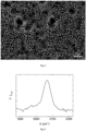
- Figure 3 A Raman spectrum of this silicon layer is shown, in which it can be seen that the layer has a completely amorphous character due to the transverse optical (TO) Raman scattering peak at approximately wave number 480 cm -1 .
- TO transverse optical
- the reaction products from Example 2 were also applied to a glass substrate by spin coating at 2000 rpm for 50 seconds and then converted at approximately 350 ° C.
- the thickness of the resulting amorphous layer was 38 nm.
- Example 4 Coating a substrate with nanoparticles using nanoparticle aerosol droplets
- a composition containing Fe 2 O 3 nanoparticles with a diameter of approximately 40 nm was dispersed in an organic/inorganic solvent mixture, added to the reaction container (1) and then converted into nanoparticle aerosol droplets using acoustic cavitation and/or capillary waves and applied to a structured substrate surface .
- a piezoceramic and the device according to Figure 1 used.
- the substrate surface was coated with the nanoparticle aerosol droplets at room temperature (approx. 23 ° C) and within a coating time of approximately 3 seconds.
- the acoustic cavitation and capillary wave formation triggered by the piezoceramic led to the formation of nanoparticle aerosol droplets that migrated through the opening (6) of the reaction container (1) and deposited on the substrate (8), which is arranged opposite the opening (6).
- the nanoparticles contained in the aerosol droplets are distributed evenly/homogeneously over the entire substrate surface, which is structured with etching craters.
- Example 5 Coating a substrate with a composition containing trisilane without the polymerization process according to the invention
- Approximately 20 ⁇ l are removed from a composition with a volume of 0.6 ml containing 11% by weight of trisilane in cyclooctane and applied to a glass substrate for 20 seconds using spin coating known from the prior art at a rotation speed of 2000 revolutions per minute (rpm). upset. After heating this glass substrate on a hot plate at 450 ° C for 5 minutes, no layer formation was observed.
- Example 6 Coating a substrate with a thermally treated composition containing trisilane without the polymerization process according to the invention
- a composition with a volume of 0.6 ml containing 11% by weight of trisilane in cyclooctane is heated on a hot plate in an open glass vessel for 625 minutes so that the composition reaches a temperature between 70 to 75 ° C.
- Fresh Trisilane is regularly added to compensate for evaporation losses.
- the composition remains transparent after this treatment.
- Approximately 20 ⁇ l are removed from this composition and applied to a glass substrate for 20 seconds using the spin coating known from the prior art at a rotation speed of 2000 revolutions per minute (rpm). After heating this glass substrate treated in this way on a hot plate at 450 ° C for 5 minutes, no layer formation was observed.
- Example 7 Coating a substrate with an acoustic cavitation treated composition containing trisilane
- a composition with a volume of 1 ml containing 18% by weight trisilane in cyclooctane is treated with a sonotrode for 145 minutes in an open glass vessel.
- the temperature of the composition remains stable at approximately 70°C.
- the composition shows a light brown color after 70 minutes of sonication with the sonotrode and a dark gray color after about 130 minutes.
- Approximately 20 ⁇ l are removed from the composition and applied to a glass substrate for 20 seconds using the spin coating known from the prior art at a rotation speed of 2000 revolutions per minute (rpm). After heating this glass substrate treated in this way on a hot plate at 450 ° C for 5 minutes, the formation of light brown, solid silicon residues can be observed on the surface.
- Example 8 Coating a substrate with a UV-treated composition containing trisilane
- a composition with a volume of 0.6 ml containing 11% by weight of trisilane in cyclooctane is irradiated for 700 minutes with UV light with a wavelength of 365 nm.
- the Composition remains transparent after this irradiation.
- 20 ⁇ l are removed from this composition treated in this way and applied to a glass substrate for 20 seconds using the spin coating known from the prior art at a rotation speed of 2000 revolutions per minute (rpm). After heating this glass substrate on a hot plate at 450 ° C for 5 minutes, no layer formation was observed.
- Example 9 Coating a substrate with a composition containing trisilane treated by acoustic cavitation and UV irradiation
- Example 7 0.2 ml is removed from the composition from Example 7, which was treated by means of acoustic cavitation as described in Example 7, and mixed with 50 ⁇ l of fresh Trisilane.
- This composition is now irradiated with UV light with a wavelength of 365 nm for 300 minutes. A lemon yellow coloring of the composition is observed.
- 20 ⁇ l are removed from this composition treated in this way and applied to a glass substrate for 20 seconds using the spin coating known from the prior art at a rotation speed of 2000 revolutions per minute (rpm). After heating this glass substrate on a hot plate at 450 ° C for 5 minutes, the formation of an approximately 20 nm thick, light orange silicon layer was observed.
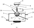
- a suitable device for carrying out the method according to the invention according to Figure 1 comprises a reaction vessel (1) with a composition (2) containing at least one hydridosilane, which is either dissolved in at least one organic and/or inorganic solvent or at least one hydridosilane which is dissolved without solvent is already present in liquid form, the hydridosilanes comprising and/or containing at least one linear and/or branched hydridosilane of the general formula Si n H 2n + 2 with n ⁇ 3 and/or a cyclic hydridosilane of the general formula Si n H 2n with n ⁇ 3 the aforementioned hydridosilane solution or the pure, already liquid hydridosilane, which contains at least mono- and/or disilane and/or a boron-containing dopant and/or phosphorus-containing dopant and/or noble gas from the group Ar, He and/or nanoparticles and/or a polymerization initiator and/or a catalyst and/or surface tension modifying agents are
- the device further comprises an ultrasound source or a sound transducer (4) for generating acoustic cavitation and/or capillary waves.
- the reaction container (1) is located (partially or completely) in a coolant container (5) provided with a coolant inlet (12) and outlet (13).
- a piezoceramic is used as the ultrasound source (4), which is not in direct contact with the composition, but rather receives the ultrasound waves (14) via an intermediate medium, in this case for example a cooling medium in a coolant container (5).
- the reaction container (1) which is surrounded by the coolant, transfers.
- the reaction container (1) has a closable opening (6), in particular for the aerosol (7).
- the composition polymerized according to the invention in a first process step can either be removed from the reaction container (1) via one of the openings (3, 6, 16) and used, for example, for subsequent spin coating, or it remains in the reaction container (1) and is converted into aerosol droplets/aerosols in a subsequent process step according to the invention.
- the substrate (8) to be coated can be arranged opposite the opening (6).
- the substrate (8) has a heating source (9) on the surface that faces away from the coating surface.
- the opening neck of the reaction container (1) can, in an advantageous embodiment of the device, be provided with a heating coil (10) and power source (11) in order to control the particle size of the aerosol ( 7) to regulate the amount of heat in which the solvent can evaporate.
- the ultrasonic waves (14) can be focused on a focal point (15) in the reaction container (1).
- the educts and products of the composition (2) can be conveyed into or out of the reaction container (1) by means of a supply/discharge pipe (16).
- gaseous silanes, dopants or other gases for example, can also be added through the supply/discharge pipe (16).
- the reaction container (1) can also have a second supply/discharge pipe (3).
- a sonotrode in which the ultrasound source also acts on the composition (2) via an intermediate medium, a sonotrode can also be used.
- the reaction container (1) can be located within a coolant container (5) provided with coolant, which can have both a coolant inlet (12) and a coolant outlet (13).
- the reaction container (1) can be designed in the form of a tube, with an expansion to accommodate a larger volume of composition, and can have two, optionally closable, openings. These openings protrude from the coolant container (5), so that from the outside of the coolant container (5) Educts and products of the process according to the invention can be supplied or removed through these openings.
- the sonotrode is arranged so that it protrudes into the coolant and is therefore only in direct contact with this coolant/intermediate.
- the transmission of the ultrasonic waves (14) to the composition (2) in the reaction container (1) for polymerization of the composition therefore also takes place here indirectly via the cooling medium, which therefore also fulfills the function of an intermediate medium.
- the sonotrode (4) can remain in the coolant container (5), sealed, for example via an O-ring.
- the composition polymerized according to the invention can either be removed from the reaction container (1) via one of the openings and used, for example, for subsequent spin coating, or it remains in the reaction container (1) and is converted into aerosol particles according to the invention in a subsequent process step.
- the substrate to be coated can optionally be arranged in front of one or both openings so that the aerosol particles formed can accumulate on this surface.
- the substrate (8) can have a heating source (9) on the surface that faces away from the coating surface.
- one or both of the openings of the reaction container (1) can be provided with a heating coil (10) and power source (11) in an advantageous embodiment of the device in order to adjust the particle size of the aerosol (7), in which the solvent can evaporate due to the heat supply.
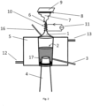
- Figure 2 shows a further device which is also suitable for carrying out the method according to the invention.
- This device according to Figure 2 also includes a reaction vessel (1) with a composition (2) containing at least one hydridosilane solution, comprising at least one linear or branched hydridosilane of the general formula Si n H 2n + 2 with n ⁇ 3 and/or a cyclic hydridosilane of the general formula Si n H 2n with n ⁇ 3, which are dissolved in at least one solvent, or a pure liquid silane solution, comprising one or more liquid hydridosilanes, which are already liquid without a solvent or a solution which optionally contains at least mono- and/or disilane and/or Boron-containing dopant and/or a phosphorus-containing dopant and/or noble gas from the group He, Ar and/or nanoparticles and/or a polymerization initiator and/or a catalyst and/or surface tension modifying agents is/are added.
- the device has an ultrasound source (4) for generating acoustic cavitation and/or capillary waves.
- a sonotrode was used.
- the reaction container (1) is located (partially or completely) in a coolant container (5) provided with a coolant inlet (12) and outlet (13).
- the reaction container (1) has an opening (6), in particular for the aerosol (7).
- the substrate (8) to be coated is opposite the opening (6) arranged.
- the substrate (8) has a heating source (9) on the surface facing away from the coating surface. If hydridosilanes are used which are dissolved in at least one solvent, the opening neck of the reaction container (1) is provided with a heating coil (10) and power source (11) in order to regulate the particle size of the aerosol (7).
- the composition (2) can be conveyed into or out of the reaction container (1) by means of a supply/discharge pipe (16).
- the reaction container (1) can also have a second supply/discharge pipe (3).
- the ultrasound source (4) for generating acoustic cavitation and/or capillary waves is a sonotrode which is arranged so that it protrudes into the reaction container (1) with the composition (2) and is thereby in direct contact with the composition (2).
- the ultrasound source (4) can remain in the reaction container (1), sealed, for example, by an O-ring (17).
- Figure 3 shows a Raman spectrum of a silicon-containing layer after conversion according to exemplary embodiment 2.
- the abscissa X indicates the wave number in [cm -1 ] and the ordinate Y indicates the Raman intensity I Raman in dimensionless units.
- the TO Raman scattering peak at approximately 480 cm -1 indicates amorphous silicon.
- Figure 4 shows a SEM (scanning electron microscope) image of a structured p-type CVD silicon layer covered in the aerosolization cell by means of aerosol coating with Fe 2 O 3 nanoparticles (white circular dots). The darker, circular areas correspond to the depressions of the etching craters.
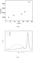
- Figure 5 shows a Fourier transform infrared spectroscopy (FTIR) spectrum of a trisilane precursor-based layer applied to a silicon wafer according to Example 9.
- the abscissa X indicates the wave number in cm -1 .
- the ordinate Y indicates the FTIR signal intensity I FTIR in relative units.
- the modes between the wave numbers 2000-2080 cm -1 are characteristic of Si-H or Si-H 2 stretching vibrations in a-Si:H.
- Figure 6 shows the growth of the molecular mass (Mw) of a composition polymerized by ultrasound treatment containing 10% by weight of cyclopentasilane (CPS) in cyclooctane.
- the abscissa X indicates the sonication time in minutes (min).
- the ordinate Y indicates the molecular mass Mw in grams per mole (g/mol).
- the M W was determined using gel permeation chromatography (GPC) using PS standards.
- the abscissa X indicates the elution time.
- the ordinate Y indicates the normalized intensity of the refractive index detector I RI .
- the sharp peak on the right in the chromatogram is generated by unreacted CPS.
- curve (A) i.e. the CPS solution treated according to the invention, an increased concentration of hydridosilanes can be determined to the left of the CPS peak, in contrast to curves (B) and (C).
Landscapes
- Chemical & Material Sciences (AREA)
- Organic Chemistry (AREA)
- Chemical Kinetics & Catalysis (AREA)
- Engineering & Computer Science (AREA)
- Materials Engineering (AREA)
- Health & Medical Sciences (AREA)
- Medicinal Chemistry (AREA)
- Polymers & Plastics (AREA)
- Mechanical Engineering (AREA)
- General Chemical & Material Sciences (AREA)
- Thermal Sciences (AREA)
- Physics & Mathematics (AREA)
- Inorganic Chemistry (AREA)
- Metallurgy (AREA)
- Life Sciences & Earth Sciences (AREA)
- Wood Science & Technology (AREA)
- Silicon Compounds (AREA)
- Silicon Polymers (AREA)
- Liquid Deposition Of Substances Of Which Semiconductor Devices Are Composed (AREA)
- Formation Of Insulating Films (AREA)
- Application Of Or Painting With Fluid Materials (AREA)
Applications Claiming Priority (2)
| Application Number | Priority Date | Filing Date | Title |
|---|---|---|---|
| DE102013020518.2A DE102013020518A1 (de) | 2013-12-11 | 2013-12-11 | Verfahren und Vorrichtung zur Polymerisation einer Zusammensetzung enthaltend Hydridosilane und anschließenden Verwendung der Polymerisate zur Herstellung von siliziumhaltigen Schichten |
| PCT/DE2014/000617 WO2015085980A1 (de) | 2013-12-11 | 2014-11-26 | Verfahren zur polymerisation einer zusammensetzung enthaltend hydridosilane und anschliessenden verwendung der polymerisate zur herstellung von siliciumhaltigen schichten |
Publications (2)
| Publication Number | Publication Date |
|---|---|
| EP3080192A1 EP3080192A1 (de) | 2016-10-19 |
| EP3080192B1 true EP3080192B1 (de) | 2023-09-20 |
Family
ID=52432606
Family Applications (1)
| Application Number | Title | Priority Date | Filing Date |
|---|---|---|---|
| EP14830938.8A Active EP3080192B1 (de) | 2013-12-11 | 2014-11-26 | Verfahren zur polymerisation einer zusammensetzung enthaltend hydridosilane und anschliessenden verwendung der polymerisate zur herstellung von siliciumhaltigen schichten |
Country Status (6)
| Country | Link |
|---|---|
| US (1) | US10053599B2 (enExample) |
| EP (1) | EP3080192B1 (enExample) |
| JP (1) | JP6586420B2 (enExample) |
| CN (1) | CN105793328B (enExample) |
| DE (1) | DE102013020518A1 (enExample) |
| WO (1) | WO2015085980A1 (enExample) |
Families Citing this family (11)
| Publication number | Priority date | Publication date | Assignee | Title |
|---|---|---|---|---|
| DE102015225289A1 (de) | 2015-12-15 | 2017-06-22 | Evonik Degussa Gmbh | Dotierte Zusammensetzungen, Verfahren zu ihrer Herstellung und ihre Verwendung |
| KR102097646B1 (ko) * | 2016-03-11 | 2020-04-06 | 가부시키가이샤 리코 | 비상 정지 압력 센서, 안전 장치 및 안전 시스템 |
| WO2017223323A1 (en) * | 2016-06-25 | 2017-12-28 | Applied Materials, Inc. | Flowable amorphous silicon films for gapfill applications |
| KR102271768B1 (ko) | 2017-04-07 | 2021-06-30 | 어플라이드 머티어리얼스, 인코포레이티드 | 반응성 어닐링을 사용하는 갭충전 |
| DE102017010263A1 (de) * | 2017-11-07 | 2019-05-09 | Forschungszentrum Jülich GmbH | Verfahren zur Herstellung von hydrogenierten amorphen siliziumhaltigen Komposit-Kolloiden und zur Verkapselung von Substanzen mit hydrogenierten amorphen siliziumhaltigen Komposit-Schichten, sowie hydrogenierte amorphe siliziumhaltige Komposit-Kolloide und mit siliziumhaltigen Komposit-Schichten verkapselte Substanzen und deren Verwendung |
| WO2019217985A1 (en) * | 2018-05-14 | 2019-11-21 | The University Of Melbourne | A method of generating radicals by ultrasound |
| US11401166B2 (en) | 2018-10-11 | 2022-08-02 | L'Air Liaquide, Société Anonyme pour l'Etude et l'Exploitation des Procédés Georges Claude | Process for producing isomer enriched higher silanes |
| US11097953B2 (en) | 2018-10-11 | 2021-08-24 | L'Air Liquide, Société Anonyme pour l'Etude et l'Exploitation des Procédés Georges Claude | Process for producing liquid polysilanes and isomer enriched higher silanes |
| US11230474B2 (en) | 2018-10-11 | 2022-01-25 | L'Air Liquide, Société Anonyme pour l'Etude et l'Exploitation des Procédés Georges Claude | Process for producing isomer enriched higher silanes |
| US10752507B2 (en) | 2018-10-11 | 2020-08-25 | L'Air Liquide, Société Anonyme pour l'Etude et l'Exploitation des Procédés Georges Claude | Process for producing liquid polysilanes and isomer enriched higher silanes |
| DE102023118799A1 (de) * | 2023-07-17 | 2025-01-23 | Forschungszentrum Jülich GmbH | Silizium Dünnschichten hergestellt durch CVD mittels Flüssigsilanen mit einstellbarem Kohlenstoffgehalt |
Family Cites Families (13)
| Publication number | Priority date | Publication date | Assignee | Title |
|---|---|---|---|---|
| JP3211255B2 (ja) * | 1990-07-10 | 2001-09-25 | 三井化学株式会社 | シラン誘導体、ポリシラン化合物、その製造方法および用途 |
| WO2000059014A1 (fr) | 1999-03-30 | 2000-10-05 | Seiko Epson Corporation | cROCEDE PRODUCTION D'UN FILM DE SILICIUM ET COMPOSITION D'ENCRE POUR IMPRIMANTE A JET D'ENCRE |
| JP2003313299A (ja) * | 2002-04-22 | 2003-11-06 | Seiko Epson Corp | 高次シラン組成物及び該組成物を用いたシリコン膜の形成方法 |
| JP2004165474A (ja) * | 2002-11-14 | 2004-06-10 | Matsushita Electric Ind Co Ltd | 光電変換素子及びその製造方法 |
| EP1599298A4 (en) * | 2003-02-20 | 2007-05-02 | Lam Res Corp | METHOD AND DEVICE FOR MEGASCULAR CLEANING OF PATTERNED SUBSTRATES |
| DE102005027757A1 (de) * | 2005-06-15 | 2006-12-28 | Gesellschaft zur Förderung von Medizin-, Bio- und Umwelttechnologien e.V. | Verfahren zur Herstellung von Polymeren |
| KR20090029494A (ko) * | 2007-09-18 | 2009-03-23 | 엘지전자 주식회사 | 비정질 실리콘 및 나노 결정질 실리콘의 복합 박막을이용한 태양전지 및 그 제조방법 |
| DE102009053806A1 (de) * | 2009-11-18 | 2011-05-19 | Evonik Degussa Gmbh | Verfahren zur Herstellung von Siliciumschichten |
| DE102010002405A1 (de) * | 2010-02-26 | 2011-09-01 | Evonik Degussa Gmbh | Verfahren zur Oligomerisierung von Hydridosilanen, die mit dem Verfahren herstellbaren Oligomerisate und ihre Verwendung |
| KR20130069611A (ko) * | 2010-04-06 | 2013-06-26 | 엔디에스유 리서치 파운데이션 | 액체 실란계 조성물 및 실리콘계 물질의 제조 방법 |
| DE102010041842A1 (de) | 2010-10-01 | 2012-04-05 | Evonik Degussa Gmbh | Verfahren zur Herstellung höherer Hydridosilanverbindungen |
| DE102010055564A1 (de) | 2010-12-23 | 2012-06-28 | Johann-Wolfgang-Goethe Universität Frankfurt am Main | Verfahren und Vorrichtung zur Abscheidung von Silizium auf einem Substrat |
| DE102013010099B4 (de) * | 2013-06-18 | 2015-07-09 | Evonik Industries Ag | Verfahren zur Herstellung strukturierter Beschichtungen, mit dem Verfahren hergestellte strukturierte Beschichtungen und ihre Verwendung |
-
2013
- 2013-12-11 DE DE102013020518.2A patent/DE102013020518A1/de not_active Ceased
-
2014
- 2014-11-26 EP EP14830938.8A patent/EP3080192B1/de active Active
- 2014-11-26 CN CN201480066856.7A patent/CN105793328B/zh not_active Expired - Fee Related
- 2014-11-26 US US15/100,831 patent/US10053599B2/en active Active
- 2014-11-26 WO PCT/DE2014/000617 patent/WO2015085980A1/de not_active Ceased
- 2014-11-26 JP JP2016538797A patent/JP6586420B2/ja not_active Expired - Fee Related
Also Published As
| Publication number | Publication date |
|---|---|
| JP6586420B2 (ja) | 2019-10-02 |
| WO2015085980A1 (de) | 2015-06-18 |
| CN105793328B (zh) | 2019-07-09 |
| DE102013020518A1 (de) | 2015-06-11 |
| JP2017509138A (ja) | 2017-03-30 |
| US20160297997A1 (en) | 2016-10-13 |
| EP3080192A1 (de) | 2016-10-19 |
| US10053599B2 (en) | 2018-08-21 |
| CN105793328A (zh) | 2016-07-20 |
Similar Documents
| Publication | Publication Date | Title |
|---|---|---|
| EP3080192B1 (de) | Verfahren zur polymerisation einer zusammensetzung enthaltend hydridosilane und anschliessenden verwendung der polymerisate zur herstellung von siliciumhaltigen schichten | |
| EP1208245B1 (de) | Plasma-cvd-verfahren und vorrichtung zur herstellung einer mikrokristallinen si:h-schicht | |
| DE69229809T2 (de) | Verfahren zur photochemischen Materialbehandlung unter Verwendung von einer zylindrischen Blitz-Lampe als Lichtquelle | |
| DE1914411A1 (de) | Beschichtungsverfahren | |
| EP4166271A1 (de) | Verfahren zum erzeugen von mindestens einer zumindest abschnittweise gewölbten oder gebogenen festkörperschicht | |
| DE102010062386B4 (de) | Verfahren zum Konvertieren von Halbleiterschichten, derartig hergestellte Halbleiterschichten sowie derartige Halbleiterschichten umfassende elektronische und optoelektronische Erzeugnisse | |
| EP2621856A2 (de) | Verfahren zur herstellung höherer hydridosilanverbindungen | |
| DE102010040231A1 (de) | p-Dotierte Siliciumschichten | |
| EP3707099B1 (de) | Verfahren zur herstellung von hydrogenierten amorphen siliciumhaltigen kolloiden und/oder komposit-kolloiden und zur verkapselung von substanzen mit hydrogenierten amorphen siliciumhaltigen komposit-kolloiden, sowie hydrogenierte amorphe siliciumhaltige kolloide und/oder komposit-kolloide und mit siliciumhaltigen komposit-schichten verkapselte substanzen und deren verwendung | |
| DE60124452T2 (de) | CVD Verfahren zum Herstellen von amorphem Silizium | |
| Lihui et al. | Studies on the formation of microcrystalline silicon with PECVD under low and high working pressure | |
| Fragouli et al. | Patterned structures of in situ size controlled CdS nanocrystals in a polymer matrix underUV irradiation | |
| WO2012072406A1 (de) | Verfahren zum konvertieren von halbleiterschichten | |
| JP2016537291A (ja) | 液体シランを使用したSiベースナノ材料の合成 | |
| WO2012130620A1 (de) | Verfahren zum herstellen von amorphen halbleiterschichten | |
| EP2588643B1 (de) | Modifizierung von siliciumschichten aus silan-haltigen formulierungen | |
| Carra et al. | Hierarchical carbon nanocone-silica metamaterials: Implications for white light photoluminescence | |
| Rai et al. | Rapid synthesis of ZnO nanostructures on woven carbon fiber using microwave treated chemical bath deposition and their characterization | |
| US20150151980A1 (en) | Nanocrystal synthesis | |
| Fadhil et al. | Preparation and characterization of zinc oxide nanoparticles by laser ablation of zinc in isopropanol | |
| Flemban | Synthesis of ZnO nanoparticles using varying pulsed laser ablation energies in liquid | |
| DE60125649T2 (de) | Verfahren zur Bildung dünner Schichten | |
| D’Amato et al. | Preparation of luminescent Si nanoparticles by tailoring the size, crystallinity and surface composition | |
| DE102018132244B4 (de) | Verfahren zur Herstellung von dotierten Halbleiterschichten | |
| Tveryanovich et al. | Production of nanodispersed materials and thin films by laser ablation techniques in liquid and in vacuum |
Legal Events
| Date | Code | Title | Description |
|---|---|---|---|
| PUAI | Public reference made under article 153(3) epc to a published international application that has entered the european phase |
Free format text: ORIGINAL CODE: 0009012 |
|
| 17P | Request for examination filed |
Effective date: 20160504 |
|
| AK | Designated contracting states |
Kind code of ref document: A1 Designated state(s): AL AT BE BG CH CY CZ DE DK EE ES FI FR GB GR HR HU IE IS IT LI LT LU LV MC MK MT NL NO PL PT RO RS SE SI SK SM TR |
|
| AX | Request for extension of the european patent |
Extension state: BA ME |
|
| DAX | Request for extension of the european patent (deleted) | ||
| RAP3 | Party data changed (applicant data changed or rights of an application transferred) |
Owner name: FORSCHUNGSZENTRUM JUELICH GMBH |
|
| STAA | Information on the status of an ep patent application or granted ep patent |
Free format text: STATUS: EXAMINATION IS IN PROGRESS |
|
| 17Q | First examination report despatched |
Effective date: 20211014 |
|
| GRAP | Despatch of communication of intention to grant a patent |
Free format text: ORIGINAL CODE: EPIDOSNIGR1 |
|
| STAA | Information on the status of an ep patent application or granted ep patent |
Free format text: STATUS: GRANT OF PATENT IS INTENDED |
|
| INTG | Intention to grant announced |
Effective date: 20230531 |
|
| GRAS | Grant fee paid |
Free format text: ORIGINAL CODE: EPIDOSNIGR3 |
|
| GRAA | (expected) grant |
Free format text: ORIGINAL CODE: 0009210 |
|
| STAA | Information on the status of an ep patent application or granted ep patent |
Free format text: STATUS: THE PATENT HAS BEEN GRANTED |
|
| AK | Designated contracting states |
Kind code of ref document: B1 Designated state(s): AL AT BE BG CH CY CZ DE DK EE ES FI FR GB GR HR HU IE IS IT LI LT LU LV MC MK MT NL NO PL PT RO RS SE SI SK SM TR |
|
| REG | Reference to a national code |
Ref country code: GB Ref legal event code: FG4D Free format text: NOT ENGLISH |
|
| RIN1 | Information on inventor provided before grant (corrected) |
Inventor name: CADIZ BEDINI, ANDREW PAOLO |
|
| REG | Reference to a national code |
Ref country code: CH Ref legal event code: EP |
|
| REG | Reference to a national code |
Ref country code: DE Ref legal event code: R096 Ref document number: 502014016685 Country of ref document: DE |
|
| REG | Reference to a national code |
Ref country code: IE Ref legal event code: FG4D Free format text: LANGUAGE OF EP DOCUMENT: GERMAN |
|
| REG | Reference to a national code |
Ref country code: LT Ref legal event code: MG9D |
|
| PG25 | Lapsed in a contracting state [announced via postgrant information from national office to epo] |
Ref country code: GR Free format text: LAPSE BECAUSE OF FAILURE TO SUBMIT A TRANSLATION OF THE DESCRIPTION OR TO PAY THE FEE WITHIN THE PRESCRIBED TIME-LIMIT Effective date: 20231221 |
|
| REG | Reference to a national code |
Ref country code: NL Ref legal event code: MP Effective date: 20230920 |
|
| PG25 | Lapsed in a contracting state [announced via postgrant information from national office to epo] |
Ref country code: SE Free format text: LAPSE BECAUSE OF FAILURE TO SUBMIT A TRANSLATION OF THE DESCRIPTION OR TO PAY THE FEE WITHIN THE PRESCRIBED TIME-LIMIT Effective date: 20230920 Ref country code: RS Free format text: LAPSE BECAUSE OF FAILURE TO SUBMIT A TRANSLATION OF THE DESCRIPTION OR TO PAY THE FEE WITHIN THE PRESCRIBED TIME-LIMIT Effective date: 20230920 Ref country code: NO Free format text: LAPSE BECAUSE OF FAILURE TO SUBMIT A TRANSLATION OF THE DESCRIPTION OR TO PAY THE FEE WITHIN THE PRESCRIBED TIME-LIMIT Effective date: 20231220 Ref country code: LV Free format text: LAPSE BECAUSE OF FAILURE TO SUBMIT A TRANSLATION OF THE DESCRIPTION OR TO PAY THE FEE WITHIN THE PRESCRIBED TIME-LIMIT Effective date: 20230920 Ref country code: LT Free format text: LAPSE BECAUSE OF FAILURE TO SUBMIT A TRANSLATION OF THE DESCRIPTION OR TO PAY THE FEE WITHIN THE PRESCRIBED TIME-LIMIT Effective date: 20230920 Ref country code: HR Free format text: LAPSE BECAUSE OF FAILURE TO SUBMIT A TRANSLATION OF THE DESCRIPTION OR TO PAY THE FEE WITHIN THE PRESCRIBED TIME-LIMIT Effective date: 20230920 Ref country code: GR Free format text: LAPSE BECAUSE OF FAILURE TO SUBMIT A TRANSLATION OF THE DESCRIPTION OR TO PAY THE FEE WITHIN THE PRESCRIBED TIME-LIMIT Effective date: 20231221 Ref country code: FI Free format text: LAPSE BECAUSE OF FAILURE TO SUBMIT A TRANSLATION OF THE DESCRIPTION OR TO PAY THE FEE WITHIN THE PRESCRIBED TIME-LIMIT Effective date: 20230920 |
|
| PGFP | Annual fee paid to national office [announced via postgrant information from national office to epo] |
Ref country code: DE Payment date: 20231120 Year of fee payment: 10 |
|
| PG25 | Lapsed in a contracting state [announced via postgrant information from national office to epo] |
Ref country code: NL Free format text: LAPSE BECAUSE OF FAILURE TO SUBMIT A TRANSLATION OF THE DESCRIPTION OR TO PAY THE FEE WITHIN THE PRESCRIBED TIME-LIMIT Effective date: 20230920 |
|
| PG25 | Lapsed in a contracting state [announced via postgrant information from national office to epo] |
Ref country code: IS Free format text: LAPSE BECAUSE OF FAILURE TO SUBMIT A TRANSLATION OF THE DESCRIPTION OR TO PAY THE FEE WITHIN THE PRESCRIBED TIME-LIMIT Effective date: 20240120 |
|
| PG25 | Lapsed in a contracting state [announced via postgrant information from national office to epo] |
Ref country code: ES Free format text: LAPSE BECAUSE OF FAILURE TO SUBMIT A TRANSLATION OF THE DESCRIPTION OR TO PAY THE FEE WITHIN THE PRESCRIBED TIME-LIMIT Effective date: 20230920 |
|
| PG25 | Lapsed in a contracting state [announced via postgrant information from national office to epo] |
Ref country code: SM Free format text: LAPSE BECAUSE OF FAILURE TO SUBMIT A TRANSLATION OF THE DESCRIPTION OR TO PAY THE FEE WITHIN THE PRESCRIBED TIME-LIMIT Effective date: 20230920 Ref country code: RO Free format text: LAPSE BECAUSE OF FAILURE TO SUBMIT A TRANSLATION OF THE DESCRIPTION OR TO PAY THE FEE WITHIN THE PRESCRIBED TIME-LIMIT Effective date: 20230920 Ref country code: IS Free format text: LAPSE BECAUSE OF FAILURE TO SUBMIT A TRANSLATION OF THE DESCRIPTION OR TO PAY THE FEE WITHIN THE PRESCRIBED TIME-LIMIT Effective date: 20240120 Ref country code: ES Free format text: LAPSE BECAUSE OF FAILURE TO SUBMIT A TRANSLATION OF THE DESCRIPTION OR TO PAY THE FEE WITHIN THE PRESCRIBED TIME-LIMIT Effective date: 20230920 Ref country code: EE Free format text: LAPSE BECAUSE OF FAILURE TO SUBMIT A TRANSLATION OF THE DESCRIPTION OR TO PAY THE FEE WITHIN THE PRESCRIBED TIME-LIMIT Effective date: 20230920 Ref country code: CZ Free format text: LAPSE BECAUSE OF FAILURE TO SUBMIT A TRANSLATION OF THE DESCRIPTION OR TO PAY THE FEE WITHIN THE PRESCRIBED TIME-LIMIT Effective date: 20230920 Ref country code: SK Free format text: LAPSE BECAUSE OF FAILURE TO SUBMIT A TRANSLATION OF THE DESCRIPTION OR TO PAY THE FEE WITHIN THE PRESCRIBED TIME-LIMIT Effective date: 20230920 Ref country code: PT Free format text: LAPSE BECAUSE OF FAILURE TO SUBMIT A TRANSLATION OF THE DESCRIPTION OR TO PAY THE FEE WITHIN THE PRESCRIBED TIME-LIMIT Effective date: 20240122 |
|
| PG25 | Lapsed in a contracting state [announced via postgrant information from national office to epo] |
Ref country code: PL Free format text: LAPSE BECAUSE OF FAILURE TO SUBMIT A TRANSLATION OF THE DESCRIPTION OR TO PAY THE FEE WITHIN THE PRESCRIBED TIME-LIMIT Effective date: 20230920 Ref country code: IT Free format text: LAPSE BECAUSE OF FAILURE TO SUBMIT A TRANSLATION OF THE DESCRIPTION OR TO PAY THE FEE WITHIN THE PRESCRIBED TIME-LIMIT Effective date: 20230920 |
|
| REG | Reference to a national code |
Ref country code: DE Ref legal event code: R097 Ref document number: 502014016685 Country of ref document: DE |
|
| REG | Reference to a national code |
Ref country code: CH Ref legal event code: PL |
|
| PG25 | Lapsed in a contracting state [announced via postgrant information from national office to epo] |
Ref country code: MC Free format text: LAPSE BECAUSE OF FAILURE TO SUBMIT A TRANSLATION OF THE DESCRIPTION OR TO PAY THE FEE WITHIN THE PRESCRIBED TIME-LIMIT Effective date: 20230920 |
|
| PG25 | Lapsed in a contracting state [announced via postgrant information from national office to epo] |
Ref country code: DK Free format text: LAPSE BECAUSE OF FAILURE TO SUBMIT A TRANSLATION OF THE DESCRIPTION OR TO PAY THE FEE WITHIN THE PRESCRIBED TIME-LIMIT Effective date: 20230920 |
|
| PG25 | Lapsed in a contracting state [announced via postgrant information from national office to epo] |
Ref country code: LU Free format text: LAPSE BECAUSE OF NON-PAYMENT OF DUE FEES Effective date: 20231126 |
|
| PG25 | Lapsed in a contracting state [announced via postgrant information from national office to epo] |
Ref country code: CH Free format text: LAPSE BECAUSE OF NON-PAYMENT OF DUE FEES Effective date: 20231130 |
|
| PLBE | No opposition filed within time limit |
Free format text: ORIGINAL CODE: 0009261 |
|
| STAA | Information on the status of an ep patent application or granted ep patent |
Free format text: STATUS: NO OPPOSITION FILED WITHIN TIME LIMIT |
|
| PG25 | Lapsed in a contracting state [announced via postgrant information from national office to epo] |
Ref country code: MC Free format text: LAPSE BECAUSE OF FAILURE TO SUBMIT A TRANSLATION OF THE DESCRIPTION OR TO PAY THE FEE WITHIN THE PRESCRIBED TIME-LIMIT Effective date: 20230920 Ref country code: LU Free format text: LAPSE BECAUSE OF NON-PAYMENT OF DUE FEES Effective date: 20231126 Ref country code: DK Free format text: LAPSE BECAUSE OF FAILURE TO SUBMIT A TRANSLATION OF THE DESCRIPTION OR TO PAY THE FEE WITHIN THE PRESCRIBED TIME-LIMIT Effective date: 20230920 Ref country code: CH Free format text: LAPSE BECAUSE OF NON-PAYMENT OF DUE FEES Effective date: 20231130 |
|
| REG | Reference to a national code |
Ref country code: BE Ref legal event code: MM Effective date: 20231130 |
|
| 26N | No opposition filed |
Effective date: 20240621 |
|
| GBPC | Gb: european patent ceased through non-payment of renewal fee |
Effective date: 20231220 |
|
| REG | Reference to a national code |
Ref country code: IE Ref legal event code: MM4A |
|
| PG25 | Lapsed in a contracting state [announced via postgrant information from national office to epo] |
Ref country code: IE Free format text: LAPSE BECAUSE OF NON-PAYMENT OF DUE FEES Effective date: 20231126 |
|
| PG25 | Lapsed in a contracting state [announced via postgrant information from national office to epo] |
Ref country code: GB Free format text: LAPSE BECAUSE OF NON-PAYMENT OF DUE FEES Effective date: 20231220 |
|
| PG25 | Lapsed in a contracting state [announced via postgrant information from national office to epo] |
Ref country code: BE Free format text: LAPSE BECAUSE OF NON-PAYMENT OF DUE FEES Effective date: 20231130 |
|
| PG25 | Lapsed in a contracting state [announced via postgrant information from national office to epo] |
Ref country code: FR Free format text: LAPSE BECAUSE OF NON-PAYMENT OF DUE FEES Effective date: 20231130 |
|
| PG25 | Lapsed in a contracting state [announced via postgrant information from national office to epo] |
Ref country code: SI Free format text: LAPSE BECAUSE OF FAILURE TO SUBMIT A TRANSLATION OF THE DESCRIPTION OR TO PAY THE FEE WITHIN THE PRESCRIBED TIME-LIMIT Effective date: 20230920 |
|
| PG25 | Lapsed in a contracting state [announced via postgrant information from national office to epo] |
Ref country code: SI Free format text: LAPSE BECAUSE OF FAILURE TO SUBMIT A TRANSLATION OF THE DESCRIPTION OR TO PAY THE FEE WITHIN THE PRESCRIBED TIME-LIMIT Effective date: 20230920 Ref country code: IE Free format text: LAPSE BECAUSE OF NON-PAYMENT OF DUE FEES Effective date: 20231126 Ref country code: GB Free format text: LAPSE BECAUSE OF NON-PAYMENT OF DUE FEES Effective date: 20231220 Ref country code: FR Free format text: LAPSE BECAUSE OF NON-PAYMENT OF DUE FEES Effective date: 20231130 Ref country code: BE Free format text: LAPSE BECAUSE OF NON-PAYMENT OF DUE FEES Effective date: 20231130 |
|
| PG25 | Lapsed in a contracting state [announced via postgrant information from national office to epo] |
Ref country code: BG Free format text: LAPSE BECAUSE OF FAILURE TO SUBMIT A TRANSLATION OF THE DESCRIPTION OR TO PAY THE FEE WITHIN THE PRESCRIBED TIME-LIMIT Effective date: 20230920 |
|
| PG25 | Lapsed in a contracting state [announced via postgrant information from national office to epo] |
Ref country code: BG Free format text: LAPSE BECAUSE OF FAILURE TO SUBMIT A TRANSLATION OF THE DESCRIPTION OR TO PAY THE FEE WITHIN THE PRESCRIBED TIME-LIMIT Effective date: 20230920 |
|
| REG | Reference to a national code |
Ref country code: AT Ref legal event code: MM01 Ref document number: 1613388 Country of ref document: AT Kind code of ref document: T Effective date: 20231126 |
|
| PG25 | Lapsed in a contracting state [announced via postgrant information from national office to epo] |
Ref country code: AT Free format text: LAPSE BECAUSE OF NON-PAYMENT OF DUE FEES Effective date: 20231126 |
|
| PG25 | Lapsed in a contracting state [announced via postgrant information from national office to epo] |
Ref country code: AT Free format text: LAPSE BECAUSE OF NON-PAYMENT OF DUE FEES Effective date: 20231126 |
|
| REG | Reference to a national code |
Ref country code: DE Ref legal event code: R119 Ref document number: 502014016685 Country of ref document: DE |
|
| PG25 | Lapsed in a contracting state [announced via postgrant information from national office to epo] |
Ref country code: CY Free format text: LAPSE BECAUSE OF FAILURE TO SUBMIT A TRANSLATION OF THE DESCRIPTION OR TO PAY THE FEE WITHIN THE PRESCRIBED TIME-LIMIT; INVALID AB INITIO Effective date: 20141126 |
|
| PG25 | Lapsed in a contracting state [announced via postgrant information from national office to epo] |
Ref country code: HU Free format text: LAPSE BECAUSE OF FAILURE TO SUBMIT A TRANSLATION OF THE DESCRIPTION OR TO PAY THE FEE WITHIN THE PRESCRIBED TIME-LIMIT; INVALID AB INITIO Effective date: 20141126 |
|
| PG25 | Lapsed in a contracting state [announced via postgrant information from national office to epo] |
Ref country code: DE Free format text: LAPSE BECAUSE OF NON-PAYMENT OF DUE FEES Effective date: 20250603 |