EP3076776A1 - Datenaktualisierungsverfahren für schaltsubstratarbeitssystem und schaltsubstratarbeitssystem - Google Patents
Datenaktualisierungsverfahren für schaltsubstratarbeitssystem und schaltsubstratarbeitssystem Download PDFInfo
- Publication number
- EP3076776A1 EP3076776A1 EP13898426.5A EP13898426A EP3076776A1 EP 3076776 A1 EP3076776 A1 EP 3076776A1 EP 13898426 A EP13898426 A EP 13898426A EP 3076776 A1 EP3076776 A1 EP 3076776A1
- Authority
- EP
- European Patent Office
- Prior art keywords
- data
- circuit board
- host computer
- data relating
- work
- Prior art date
- Legal status (The legal status is an assumption and is not a legal conclusion. Google has not performed a legal analysis and makes no representation as to the accuracy of the status listed.)
- Granted
Links
- 238000000034 method Methods 0.000 title claims abstract description 48
- 239000000758 substrate Substances 0.000 title 2
- 230000008859 change Effects 0.000 claims abstract description 42
- 230000008569 process Effects 0.000 abstract description 30
- 238000012546 transfer Methods 0.000 abstract description 11
- 230000009467 reduction Effects 0.000 abstract description 4
- 238000004519 manufacturing process Methods 0.000 description 19
- 238000011960 computer-aided design Methods 0.000 description 11
- 230000000694 effects Effects 0.000 description 8
- 239000000853 adhesive Substances 0.000 description 7
- 230000001070 adhesive effect Effects 0.000 description 7
- 238000012545 processing Methods 0.000 description 7
- 238000010586 diagram Methods 0.000 description 6
- 101100537098 Mus musculus Alyref gene Proteins 0.000 description 5
- 101150095908 apex1 gene Proteins 0.000 description 5
- 238000003860 storage Methods 0.000 description 4
- 101100272621 Drosophila melanogaster BomS2 gene Proteins 0.000 description 3
- 238000005516 engineering process Methods 0.000 description 3
- 101100269674 Mus musculus Alyref2 gene Proteins 0.000 description 2
- 239000012530 fluid Substances 0.000 description 2
- 229910000679 solder Inorganic materials 0.000 description 2
- 101100272622 Drosophila melanogaster BomS3 gene Proteins 0.000 description 1
- 238000013475 authorization Methods 0.000 description 1
- 238000004891 communication Methods 0.000 description 1
- 239000000470 constituent Substances 0.000 description 1
- 238000012937 correction Methods 0.000 description 1
- 230000001934 delay Effects 0.000 description 1
- 238000013461 design Methods 0.000 description 1
- 238000001514 detection method Methods 0.000 description 1
- 239000000446 fuel Substances 0.000 description 1
- 230000006870 function Effects 0.000 description 1
- 238000007689 inspection Methods 0.000 description 1
- 230000010354 integration Effects 0.000 description 1
- 239000000463 material Substances 0.000 description 1
- 239000000155 melt Substances 0.000 description 1
- 238000012986 modification Methods 0.000 description 1
- 230000004048 modification Effects 0.000 description 1
- 238000004904 shortening Methods 0.000 description 1
- 230000001360 synchronised effect Effects 0.000 description 1
Images


Classifications
-
- G—PHYSICS
- G05—CONTROLLING; REGULATING
- G05B—CONTROL OR REGULATING SYSTEMS IN GENERAL; FUNCTIONAL ELEMENTS OF SUCH SYSTEMS; MONITORING OR TESTING ARRANGEMENTS FOR SUCH SYSTEMS OR ELEMENTS
- G05B19/00—Programme-control systems
- G05B19/02—Programme-control systems electric
- G05B19/18—Numerical control [NC], i.e. automatically operating machines, in particular machine tools, e.g. in a manufacturing environment, so as to execute positioning, movement or co-ordinated operations by means of programme data in numerical form
- G05B19/4155—Numerical control [NC], i.e. automatically operating machines, in particular machine tools, e.g. in a manufacturing environment, so as to execute positioning, movement or co-ordinated operations by means of programme data in numerical form characterised by programme execution, i.e. part programme or machine function execution, e.g. selection of a programme
-
- G—PHYSICS
- G05—CONTROLLING; REGULATING
- G05B—CONTROL OR REGULATING SYSTEMS IN GENERAL; FUNCTIONAL ELEMENTS OF SUCH SYSTEMS; MONITORING OR TESTING ARRANGEMENTS FOR SUCH SYSTEMS OR ELEMENTS
- G05B19/00—Programme-control systems
- G05B19/02—Programme-control systems electric
- G05B19/418—Total factory control, i.e. centrally controlling a plurality of machines, e.g. direct or distributed numerical control [DNC], flexible manufacturing systems [FMS], integrated manufacturing systems [IMS], computer integrated manufacturing [CIM]
- G05B19/4185—Total factory control, i.e. centrally controlling a plurality of machines, e.g. direct or distributed numerical control [DNC], flexible manufacturing systems [FMS], integrated manufacturing systems [IMS], computer integrated manufacturing [CIM] characterised by the network communication
-
- H—ELECTRICITY
- H05—ELECTRIC TECHNIQUES NOT OTHERWISE PROVIDED FOR
- H05K—PRINTED CIRCUITS; CASINGS OR CONSTRUCTIONAL DETAILS OF ELECTRIC APPARATUS; MANUFACTURE OF ASSEMBLAGES OF ELECTRICAL COMPONENTS
- H05K13/00—Apparatus or processes specially adapted for manufacturing or adjusting assemblages of electric components
- H05K13/08—Monitoring manufacture of assemblages
- H05K13/0882—Control systems for mounting machines or assembly lines, e.g. centralized control, remote links, programming of apparatus and processes as such
-
- G—PHYSICS
- G05—CONTROLLING; REGULATING
- G05B—CONTROL OR REGULATING SYSTEMS IN GENERAL; FUNCTIONAL ELEMENTS OF SUCH SYSTEMS; MONITORING OR TESTING ARRANGEMENTS FOR SUCH SYSTEMS OR ELEMENTS
- G05B2219/00—Program-control systems
- G05B2219/30—Nc systems
- G05B2219/31—From computer integrated manufacturing till monitoring
- G05B2219/31399—Station corrects nc program, sends back modified program to program generator
-
- G—PHYSICS
- G05—CONTROLLING; REGULATING
- G05B—CONTROL OR REGULATING SYSTEMS IN GENERAL; FUNCTIONAL ELEMENTS OF SUCH SYSTEMS; MONITORING OR TESTING ARRANGEMENTS FOR SUCH SYSTEMS OR ELEMENTS
- G05B2219/00—Program-control systems
- G05B2219/30—Nc systems
- G05B2219/31—From computer integrated manufacturing till monitoring
- G05B2219/31422—Upload, download programs, parameters from, to station to, from server
-
- G—PHYSICS
- G05—CONTROLLING; REGULATING
- G05B—CONTROL OR REGULATING SYSTEMS IN GENERAL; FUNCTIONAL ELEMENTS OF SUCH SYSTEMS; MONITORING OR TESTING ARRANGEMENTS FOR SUCH SYSTEMS OR ELEMENTS
- G05B2219/00—Program-control systems
- G05B2219/30—Nc systems
- G05B2219/31—From computer integrated manufacturing till monitoring
- G05B2219/31484—Operator confirms data if verified data is correct, otherwise amends data
-
- G—PHYSICS
- G05—CONTROLLING; REGULATING
- G05B—CONTROL OR REGULATING SYSTEMS IN GENERAL; FUNCTIONAL ELEMENTS OF SUCH SYSTEMS; MONITORING OR TESTING ARRANGEMENTS FOR SUCH SYSTEMS OR ELEMENTS
- G05B2219/00—Program-control systems
- G05B2219/30—Nc systems
- G05B2219/32—Operator till task planning
- G05B2219/32148—Enter correction data at a station, also transmitted to all downstream stations
-
- G—PHYSICS
- G05—CONTROLLING; REGULATING
- G05B—CONTROL OR REGULATING SYSTEMS IN GENERAL; FUNCTIONAL ELEMENTS OF SUCH SYSTEMS; MONITORING OR TESTING ARRANGEMENTS FOR SUCH SYSTEMS OR ELEMENTS
- G05B2219/00—Program-control systems
- G05B2219/30—Nc systems
- G05B2219/34—Director, elements to supervisory
- G05B2219/34038—Web, http, ftp, internet, intranet server
-
- G—PHYSICS
- G05—CONTROLLING; REGULATING
- G05B—CONTROL OR REGULATING SYSTEMS IN GENERAL; FUNCTIONAL ELEMENTS OF SUCH SYSTEMS; MONITORING OR TESTING ARRANGEMENTS FOR SUCH SYSTEMS OR ELEMENTS
- G05B2219/00—Program-control systems
- G05B2219/30—Nc systems
- G05B2219/45—Nc applications
- G05B2219/45029—Mount and solder parts on board
-
- G—PHYSICS
- G05—CONTROLLING; REGULATING
- G05B—CONTROL OR REGULATING SYSTEMS IN GENERAL; FUNCTIONAL ELEMENTS OF SUCH SYSTEMS; MONITORING OR TESTING ARRANGEMENTS FOR SUCH SYSTEMS OR ELEMENTS
- G05B2219/00—Program-control systems
- G05B2219/30—Nc systems
- G05B2219/45—Nc applications
- G05B2219/45035—Printed circuit boards, also holes to be drilled in a plate
-
- Y—GENERAL TAGGING OF NEW TECHNOLOGICAL DEVELOPMENTS; GENERAL TAGGING OF CROSS-SECTIONAL TECHNOLOGIES SPANNING OVER SEVERAL SECTIONS OF THE IPC; TECHNICAL SUBJECTS COVERED BY FORMER USPC CROSS-REFERENCE ART COLLECTIONS [XRACs] AND DIGESTS
- Y02—TECHNOLOGIES OR APPLICATIONS FOR MITIGATION OR ADAPTATION AGAINST CLIMATE CHANGE
- Y02P—CLIMATE CHANGE MITIGATION TECHNOLOGIES IN THE PRODUCTION OR PROCESSING OF GOODS
- Y02P90/00—Enabling technologies with a potential contribution to greenhouse gas [GHG] emissions mitigation
- Y02P90/02—Total factory control, e.g. smart factories, flexible manufacturing systems [FMS] or integrated manufacturing systems [IMS]
Definitions
- the present invention relates to an updating method of data relating to a circuit board work system in which electronic components are mounted onto a circuit board such as a printed wiring board, and relates to the circuit board work system.
- circuit board work system which uses a database server in the control of the circuit board work system in which a printed circuit board or the like is produced by mounting electronic components onto the printed circuit board (PTL 1 or the like).
- the circuit board work system disclosed in PTL 1 is a system in which a circuit board working machine such as a screen printer, an adhesive application machine, an electronic component mounting machine, or a reflow furnace is controlled by a host computer.
- a control computer of each circuit board working machine directly accesses a database server, and collects data relating to a work target circuit board, for example, data such as the type of electronic components which are supplied from component feeders with which the electronic component mounting machine is provided, the shapes of the components, and the mounting positions.
- setting data in PTL 1, a control program or a recipe
- the control computer of each circuit board working machine executes the mounting operation or the like based on the setting data which is created by the host computer.
- the control computer performs a process in which the changed content of the data is reported to the host computer.
- the host computer executes a process in which a recipe which is newly created based on the updated data is transferred to the control computer.
- the control computer receives the updated information from the host computer, all of the newly created setting data is received and used to replace the setting data being executed, and thus, the changed content is reflected in the created setting data.
- the setting data includes data of the component type and the mounting position of the component for each of a plurality of electronic components to be mounted onto one circuit board, the data amount increases in accordance with an increase in the number of electronic components to be mounted, that is, an increase in the integration density.
- the present invention was made in light of the problems described above, and an object thereof is to provide a data updating method of a circuit board work system and the circuit board work system which are capable of obtaining a reduction in transfer time while reliably transferring changed content of data relating to a work target circuit board between a database server and a circuit board working machine.
- a data updating method of a circuit board work system includes a plurality of circuit board working machines each of which is provided with a control computer and which performs work on a circuit board, a host computer which is provided to be shared by the plurality of circuit board working machines and which manages each of the control computers, and a database server in which data relating to a work target circuit board is stored, the method including a step of reporting a change in data relating to the work target circuit board to the host computer, a step of updating the data which is stored in the database server based on the change in the data relating to the work target circuit board for which the report is received, and a step of acquiring partial data relating to the update among the data items which are stored in the database server by the control computer.
- a circuit board work system which is made in light of the problems described above includes a plurality of circuit board working machines each of which is provided with a control computer and which performs work on a circuit board, a host computer which is provided to be shared by the plurality of circuit board working machines and which manages each of the control computers, a database server in which data relating to a work target circuit board is stored, a change reporting section which reports a change in data relating to the work target circuit board to the host computer, a database updating section which updates the data which is stored in the database server based on the change in the data relating to the work target circuit board for which the report is received, and a data acquisition section which is provided in the control computer and acquires partial data relating to the update by the database updating section.
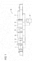
- Fig. 1 schematically illustrates an electronic component mounting system 10 which is an embodiment of the present invention.
- the electronic component mounting system 10 is provided with a screen printer 11, an adhesive application machine 12, electronic component mounting machines (hereinafter shortened to "component mounting machines") 14 and 16, and a reflow furnace 18 which are arranged lined up in a row, and a system control device 20 which unifies and controls these elements.
- the screen printer 11 moves a squeegee along a mask using a squeegee moving device and prints solder paste onto a circuit board 13 (refer to Fig. 2 ) such as a printed wiring board which is conveyed in the production line via through-holes in the mask, for example.
- the adhesive application machine 12 is a high viscosity fluid application machine which applies, as a temporary adhesive, a high viscosity fluid to a plurality of locations on the circuit board 13 which is conveyed in the production line, for example.
- the component mounting machines 14 and 16 mount components onto a plurality of locations on the circuit board 13 at which the temporary adhesive is applied, and the component mounting operation in relation to the one circuit board 13 is performed by work division, for example, the component mounting machine 14 mounts comparatively small electronic components, and the component mounting machine 16 mounts comparatively large or abnormally shaped electronic components.
- the reflow furnace 18 melts solder and electrically connects the electronic components onto the circuit board 13.
- the main constituent of the system control device 20 is a host computer (in the description of the present embodiment, a computer includes not only a data processing device but also an external input device and a display) which carries out intensive management of the production line which is formed of the plurality of circuit board working machines from the screen printer 11 to the reflow furnace 18.
- Board handling devices 22 and 24 which subject the circuit board 13 to conveying, waiting, vertical inversion, and the like are provided between the adhesive application machine 12 and the component mounting machine 14, and between the component mounting machines 14 and 16, respectively.
- the board handling devices 22 and 24 may include a pair of belt conveyors which extend in the conveyance direction and a drive motor which is the drive source, and supply the circuit board 13 each time it is possible to receive the circuit board 13 in the downstream side circuit board working machine.
- Each of the circuit board working machines described above is provided with a control computer. Since the configurations of the control computers are substantially the same, description will be given representatively of the component mounting machine 16.
- a plurality (two in the example illustrated in Fig. 1 ) of the component mounting machines 16 are provided lined up in the conveyance direction of the circuit board 13 of the production line.
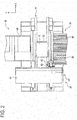
- the component mounting machine 16 is an XY robot type mounting machine in which a mounting head 45 is moved to an arbitrary position on an XY coordinate plane.
- the component mounting machine 16 is provided with a board conveyor 31, and a board holding device 32 is provided on a portion of the board conveyor 31.
- a component supply device 34 is installed along the board conveyor 31 in the component mounting machine 16.
- a plurality of component feeders 36 are mounted lined up in the component supply device 34. Each of the plurality of component feeders 36 stores multiple components, and sequentially positions the components at a component supply section which is determined in advance.
- a mounting device 38 performs mounting operation of receiving the component from the component supply section and mounting the component onto the circuit board 13 which is held in the board holding device 32.
- the mounting device 38 is provided with a head moving device 43, which is configured by an XY robot provided with an X-axis slide 41 and a Y-axis slide 42, and the mounting head 45 which is moved by the head moving device 43.
- the mounting head 45 holds a suction nozzle in a detachable manner using a nozzle holding section (omitted from the drawings).
- the mounting head 45 receives the component from the component feeder 36 using the suction nozzle at a component reception position, and mounts the component onto a predetermined position of the circuit board 13 which is held by the board holding device 32 at a component mounting position.
- the suction nozzle rotates the held component by being rotated by a nozzle rotating device, as necessary.
- the component supply device 46 is a tray-type component supply device, stores multiple components in a component tray, and supplies the components onto the mounting head 45.
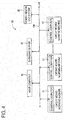
- Fig. 3 is a block diagram illustrating the configuration of the component mounting machine 16.
- a control computer 51 is provided with a processing unit (PU) 53, a read only memory (ROM) 54, a random access memory (RAM) 55, an input-output interface 57, and a bus which connects these elements.
- An X-axis slide drive motor 63, a Y-axis slide drive motor 64, a lifting and lowering motor 65, and a rotation motor 66 are connected to the input-output interface 57 via drive circuits 61.
- the X-axis slide drive motor 63 and the Y-axis slide drive motor 64 are motors which drive the X-axis slide 41 and the Y-axis slide 42 illustrated in Fig. 2 .
- the lifting and lowering motor 65 and the rotation motor 66 are a motor which drives the nozzle lifting and lowering device to lift and lower the suction nozzle and a motor which drives the nozzle rotating device to rotate the suction nozzle.
- Two cameras, a fiducial mark camera 68 which images fiducial marks on the circuit board 13, and a component camera 69 which images the component that is held by the suction nozzle of the mounting head 45 are connected to the input-output interface 57 via control circuits 71.
- the control computer 51 controls each of the motors 63 to 66 and each of the cameras 68 and 69 in cooperation with the drive circuits 61 and the control circuits 71.
- the control computer 51 is connected to a database server 81, a host computer 82, and the like via the input-output interface 57.
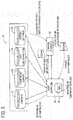
- Fig. 4 illustrates the network configuration of the electronic component mounting system 10.
- the control computer 51 of the plurality of circuit board working machines (the component mounting machines 16 and the like) described above is connected to the database server (hereinafter referred to as a "DB server") 81, the host computer 82, and a board design Computer-Aided Design (CAD) system 83 using a local network (hereinafter referred to as a "LAN”) 100.
- the DB server 81, the host computer 82, and the CAD system 83 form the system control device 20 described above.
- the host computer 82 creates a recipe which is setting data instructing work content to be performed by each of the plurality of circuit board working machines, specifically, setting data for the control computer 51 which is necessary in the control of each of the circuit board working machines, and transfers the setting data to each of the circuit board working machines.
- the host computer 82 creates a recipe instructing work content such as "which electronic component is to be mounted at which mounting coordinates of the printed circuit board which is conveyed" in relation to each of the component mounting machines 14 and 16 before board production based on the data (refer to Figs. 5 and 6 ) which is stored in the DB server 81.
- sequence data 110 (refer to Fig.
- the host computer 82 refers to the CAD data which is stored in the CAD system 83.
- the DB server 81 and the CAD system 83 are shared by a plurality of the electronic component mounting systems 10 (production lines), and a configuration may be adopted in which the host computer 82 of another production line accesses the DB server 81 and the CAD system 83 via the LAN 100.
- the network via the LAN 100 illustrated in Fig. 4 may be configured such that a device other than the depicted devices is capable of connecting, for example, and may be a configured such that a portable terminal on which software capable of changing the data which is stored in the DB server 81 is installed is capable of connecting using wireless communication.
- Fig. 5 schematically illustrates data transfer between the database server 81, the host computer 82, and the control computer 51.
- the JOB data 91 stores information of the circuit board 13 (refer to Fig. 2 ), information indicating which components are to be mounted onto which positions on the circuit board 13, and the like.
- Fig. 6 illustrates a portion of the JOB data 91, for example, the data groups of the configuration illustrated in Fig. 6 are set in the JOB data 91, and a recipe including a portion or the entirety of the data groups is created.
- sequence data 110 is data relating to the coordinate positions at which to mount the electronic components onto the circuit board 13.
- Mounting coordinates of the electronic components (X-axis coordinate (X1, X2, X3, ...), Y-axis coordinate (Y1, Y2, Y3, ...), a rotational angle (for example, an angle ( ⁇ 1, ⁇ 2, ⁇ 3, ... ) in a rotation direction in a plane which is level with the XY coordinate plane), and a circuit symbol (Ref1, Ref2, Ref3, ...)) are set in the sequence data 110.
- Plural items of data indicating the mounting coordinates and the circuit symbols are, for example, related to one record in which each item of data such as X1 - Y1 - ⁇ 1 - Ref1 is a field.
- the BOM data 112 is data relating to a BOM (Bills of Materials: component table) which is set for each type of printed circuit board. Data relating to a plurality of BOMs (BOM1, BOM2, ...) is set in the BOM data 112. For example, in BOM1, the circuit symbols (Ref1, Ref2, Ref3, ...) are related to the component types (a, b, c, ...) of the electronic components. The circuit symbols and the component types are related as, for example, Ref1 - a. In the other BOMs from BOM2 onward, the circuit symbols are related to the component types in the same manner as in BOM1.
- Data relating to the shapes and supply modes of the electronic components is set in the part data 113.
- the component type of the electronic components (a, b, c, d, ...), the shape of each electronic component (X-axis length (x1, x2, x3 , x4 , ...), Y-axis length (y1, y2, y3, y4, ...), and lead type (r1, r2, r3, r4, ...)), and supply mode data of each electronic component (for example, if a tape feeder is used, data indicating how many millimeters the tape is, at how many millimeters interval the storage positions of the components are provided, and the like for the component tape) are set in the part data 113.
- Plural items of data indicating the shape and supply mode of the electronic component are, for example, related in a manner such as a - x1 - y1 - r1 - (data indicating 8 mm tape, 4 mm feed).
- the part data 113 is data which is used in common by a plurality of board types. Data in which the board type (Key1, Key2, Key3, ...) is related to the BOM (BOM1, BOM2, BOM3, ...) is set in the board type correlation data 114.
- DB server 81 is set such that, in a case in which there is a change to one of the databases of the two databases (the JOB data 91 and the component library 92), for example, the change is not reflected in the other database until the host computer 82 approves the changed content under the instruction of a supervisor of the production line or the like.
- settings may be adopted in which, in a case in which there is a change in the data in one of the two databases (the JOB data 91 and the component library 92), the data is automatically synchronized with the other database.
- the line configurations 94 illustrated in Fig. 5 is information relating to the configurations of all of the production lines which are managed by the host computer 82, and, for example, includes information indicating the order of the plurality of circuit board working machines which are lined up in a row to be connected in each production line.
- Data relating to management information of the database itself such as the storage position of each item of data, and data relating to the configuration of each circuit board working machine (for example, the types of suction nozzle which may be mounted, and the like) is stored in the system settings 95.
- the host computer 82 accesses the DB server 81 in which the four databases described above are stored and executes processes such as acquisition and updating of data.
- the configuration of the data which is stored in the DB server 81 illustrated in Fig. 5 is an example, and is changed, as appropriate, by carrying out importing of a database, addition of records, and the like as necessary according to changes in the production line or the like.
- step S1 (hereinafter shortened to S1, and the same also applies to the other steps) illustrated in Fig. 7 , the sequence data 110 (refer to Fig. 6 ) is created by the host computer 82.
- CAD data relating to the component type of the electronic components and the mounting coordinates is stored in the CAD system 83.
- a worker or the like creates the sequence data 110 relating to the board type (for example, Key1) of the printed circuit board which is the production target by operating the host computer 82.
- the host computer 82 refers to the CAD data of the CAD system 83 corresponding to an operation of the worker or the like and generates the sequence data 110.
- the electronic component mounting system 10 may be configured such that the production target board type is input automatically.
- the electronic component mounting system 10 may be configured to read the identification code which is displayed on the printed circuit board using the fiducial mark camera 68 which is provided on the component mounting machine 14, and the production target board type may be automatically input to the host computer 82 based on the read identification code.
- the host computer 82 refers to the board type correlation data 114 of the JOB data 91 and selects the BOM (for example BOM1) corresponding to the board type Key1.
- the host computer 82 refers to the circuit symbol (Ref1, ...) of each item of data of the sequence data 110 and the BOM data 112 (BOM1) and relates the two items of data. Accordingly, which component type (a, b, c, ...) is mounted at which mounting coordinates (the X-axis coordinate, the Y-axis coordinate, and the rotational coordinate) of the production target printed circuit board.
- the host computer 82 refers to the component type (a, b, c, ...) of each item of data of the BOM data 112 (BOM1) and the part data 113 and relates the two items of data. Accordingly, data indicating which electronic component is mounted at which mounting coordinates of the production target printed circuit board is created. The host computer 82 sets the other necessary data (the number of the circuit boards 13 (refer to Fig. 2 ) to be produced or the like) in the data and creates a recipe.
- this recipe is transferred to the necessary control computer 51 via the LAN 100 after the host computer 82 determines which electronic components to mount onto the circuit board 13 using which of the component mounting machines 14 and 16 (S3, refer to Fig. 5 ).
- the transferring of the recipe may be carried out automatically by the host computer 82 from the DB server 81 toward each of the control computers 51; however, the transferring of the recipe may also be carried according to operation of the host computer 82 or the control computer 51.
- Each of the circuit board working machines of the electronic component mounting system 10 executes staged mounting operation according to the allocated recipe.
- Each of the control computers 51 controls each of the circuit board working machines based on the transferred recipe; however, whether or not there is some kind of problem in the recipe is monitored by a worker (a worker in charge, a supervisor, an inspector of the produced electronic circuit, or the like) of the circuit board working machine.
- a worker a worker in charge, a supervisor, an inspector of the produced electronic circuit, or the like
- the worker in charge of the circuit board working machine performs an input process or the like which changes the problematic data by operating the circuit board working machine (the control computer 51). More specifically, for example, the component mounting machine 16 detects the error of the holding position based on the image data in which the electronic component in a state of being held by the suction nozzle of the mounting head 45 is captured by the component camera 69. There is a case in which an error arises in the processing results in relation to the image data due to the device-specific characteristics (differences in the brightness and the like) such as the lighting with which the mounting head 45 is provided.
- the worker amends the data relating to the shapes of the components in the recipe.
- the worker amends the data relating to the mounting positions contained in the recipe.
- the control computer 51 which receives the changes of the data in S6 reports the changed content of the recipe data to the host computer 82 without reflecting the changes in the recipe being executed (S7, refer to Fig. 5 ). For example, this is because it is necessary to link the recipes provided in both the control computer 51 side and the host computer 82 side after confirming, verifying, and the like the changed content using the host computer 82.
- control computer 51 receives data changes, for example, a person performing input operates an external input device while viewing the display of a display and inputs the necessary data (there is no problem even if plural items of data are included), and if input determining that the data will be changed is performed at the time at which the input is completed, a process in which the changed content is reported to the host computer 82 is performed.
- the host computer 82 temporarily accumulates the recipe of each of the control computers 51 as work data in a memory device 85 (refer to Fig. 5 ) such as a hard disk. Before updating the data of the DB server 81, the host computer 82 updates the work data which is stored in the memory device 85 based on the recipe changes for which reports are received (S8, refer to Fig. 5 ). The host computer 82 holds the content of the recipe changes for which reports are received in the memory device 85 until the worker performs an approving process using an external input device or the like (S9: NO). Note that, the destination in which to temporarily save the recipes as work data is not limited to the memory device 85 with which the host computer 82 is provided, and may be another device capable of storage (the DB server 81 or the like).
- the host computer 82 when the host computer 82 receives recipe changes based on input data obtained by a worker operating an external input device, for example, (S5), the host computer 82 changes the recipe data of the memory device 85 and does not update the data of the DB server 81 until the final acceptance is performed by the worker (S9: NO).
- the host computer 82 updates the data of the DB server 81 based on the change in the data of the memory device 85 according to the acceptance (S9: YES) by the worker (S10). Note that, depending on the determination of the worker, in a case in which there is a mistake in the content of the data for which a report is received from the control computer 51, amendment of the changed content and notification of an error to the control computer 51 are performed by the host computer 82.
- the host computer 82 is provided with a device (a card reader for reading an identification card or the like) for identifying the worker performing the operation, and that the host computer 82 is configured to determine whether or not the worker which accepts the data changes has operating authorization.
- a device a card reader for reading an identification card or the like
- the host computer 82 executes control in which, of the data which is stored in the DB server 81, only the changed portion is transferred to the control computer 51.
- the host computer 82 transmits an instruction indicating that only the partial data relating to the updates among the data which is stored in the DB server 81 is to be acquired to the control computer 51 which receives the recipe changes (S11).
- the host computer 82 transmits an instruction indicating that data is to be acquired to the control computer 51 which includes the data of the DB server 81 which is updated in S10, that is, which uses the data relating to the changes in the control (S11).
- the control computer 51 executes a process in which only the partial data relating to the updates is transferred from the DB server 81 according to the instruction from the host computer 82 (S12, refer to Fig. 5 ).
- the host computer 82 may be set to transmit instructions permitting the reflection of the recipe with the changed content which is received by the control computer 51 as it is to the control computer 51 as a "updated data acquisition instruction".
- control computer 51 may be set to temporarily store the changed content which is received in the memory or the like until there is an instruction from the host computer 82, and to perform a process in which the content which is stored in the memory is reflected in the recipe when an instruction is received.
- control computer 51 executes a process in which the partial data relating to the updates which are transferred from the DB server 81 is reflected in the recipe with which the control computer 51 is provided (S13). At this time, the control computer 51 executes the changes of only the data which is necessary among the data contained in the recipe, for example.
- the control computer 51 determines whether or not the control computer 51 is in a state in which it is possible to change the recipe of the control computer 51. For example, in a case in which the control computer 51 of the component mounting machine 14 or 16 is executing the mounting operation of a component onto the circuit board 13 based on the created recipe, it is not desirable for the data of the mounting position of the component to be changed.
- the control computer 51 reflects the changes of the data in the recipe while performing a determination of whether or not there are presently items of data which are possible to change among the items of data to be changed. Note that, a configuration may be adopted in which, for the transferring of the data relating to the update, the process is started using a query from the control computer 51 toward the host computer 82 as a starting point.
- the host computer 82 executes a process in which a recipe which is newly created based on the updated data of the DB server 81 is transferred to the necessary control computers 51.
- the control computer 51 receives an instruction from the host computer 82, all of the newly created recipe data is received and used to replace the recipe data being executed, and thus, the changed content is reflected in the created recipe. Therefore, the control computer 51 must perform a process in which the entirety of the recipe is received anew every time there is an operation in which the data of the created recipe is changed, and there is a concern that the data transfer time between the control computer 51 and the DB server 81 will become longer and that delays or the like will arise in the post-change work.
- the host computer 82 executes control in which, of the data which is stored in the DB server 81, only the changed portion is transferred to the control computer 51. Accordingly, it is possible to achieve a reduction in the data amount to be transferred when the electronic component mounting system 10 transfers data relating to a change in a recipe between the DB server 81 and each of the control computers 51 (the circuit board working machines). The processing time until the control computer 51 receives the data, in which the data amount is reduced, to be received from the DB server 81 is shortened.
- the electronic component mounting system 10 since the transferred data amount is limited to only the necessary portion, the error occurrence rate in the data transfer is reduced and error detection, correction, processing in a case in which an error occurs becomes easy. As a result, it is possible to configure the electronic component mounting system 10 in which a shortening in the transfer time can be obtained while reliably transferring the changed content of the recipe data between the DB server 81 and each of the circuit board working machines.
- the electronic component mounting system 10 is an example of a circuit board work system.
- the recipe (the setting data), and each of the databases of the DB server 81 (the JOB data 91, the component library 92, the line configurations 94, and the system settings 95) is an example of the data relating to the work target circuit board.
- a portion of the control computer 51 of the circuit board working machine which receives the change in the recipe which reports the changed content to the host computer 82 is an example of a change reporting section.
- a portion which updates the data which is stored in the DB server 81 based on the changed content of the host computer 82 which receives the report of the recipe changes is an example of a database updating section.
- a portion of the control computer 51 which receives the recipe changes which acquires only the partial data which is updated by the host computer 82 among the data which is stored in the DB server 81 is an example of a data acquisition section.
- the present invention is not limited to the embodiment described above, and it goes without saying that various improvements and modifications are possible within a scope that does not depart from the gist of the present invention.
- the host computer 82 is capable of accessing the DB server 81; however, the control computer 51 of each of the circuit board working machines may also be configured to be capable of directly accessing the DB server 81 without going through the host computer 82.
- a configuration may also be adopted in which the DB server 81 periodically confirms whether or not there are recipe changes from the control computer 51 to the host computer 82, and regardless of the control of the host computer 82, the DB server 81 refers to the changed content which is reported to the host computer 82 and updates the database itself.
- control computer 51 reports the changed content of the recipe which is received to the host computer 82; however, another device (the DB server 81 or a portable terminal) which is connected to the LAN 100 may confirm the changed content of the recipe which is received by the control computer 51 and report the changed content to the host computer 82, or the host computer 82 may periodically confirm the changed content of the control computer 51.
- another device the DB server 81 or a portable terminal
- the host computer 82 may periodically confirm the changed content of the control computer 51.
- the device which temporarily saves the recipes as work data is not limited to the memory device 85 with which the host computer 82 is provided, and may be another device capable of storage (the DB server 81 or the like).
- the DB server 81 may execute a process in which the work data is accumulated, the work data is updated based on the changed content, and the change in the work data are reflected in the database according to the approval of the host computer 82 (the worker).
- the process content illustrated in Figs. 7 and 8 are examples and may be changed as appropriate.
- the host computer 82 is configured to execute a process in which, before updating the data of the DB server 81, the host computer 82 updates the work data which is saved in the memory device 85 and waits until the approval of the worker; however, a configuration may be adopted in which the host computer automatically verifies the validity and the like of the data of the changed content for which a report is received and reflects the data of the changed content in the DB server 81 after approval is performed. In this case, it is possible to omit the memory device 85 which stores the work data and the process of S8 illustrated in Fig. 8 .
- the control computer 51 may be configured to include a function of creating a recipe (setting data) based on the data which is stored in the DB server 81.
- the electronic component mounting system 10 may be configured such that the updating of the recipe may not be carried out using the host computer 82, but may be carried out only by the control computer 51. In this case, it is possible to omit the processes of S4 and S5 of Fig. 7 .
- the present application is not limited thereto, and may be applied to which shares data which is common to the database server in other various production lines.
- the present application may be applied to the data updating of setting data for a control computer which controls each work robot in a production line using work robots which carry out assembly work of secondary cells (solar cells, fuel cells, or the like) or the like.
Applications Claiming Priority (1)
| Application Number | Priority Date | Filing Date | Title |
|---|---|---|---|
| PCT/JP2013/082180 WO2015079560A1 (ja) | 2013-11-29 | 2013-11-29 | 対回路基板作業システムのデータ更新方法及び対回路基板作業システム |
Publications (3)
| Publication Number | Publication Date |
|---|---|
| EP3076776A1 true EP3076776A1 (de) | 2016-10-05 |
| EP3076776A4 EP3076776A4 (de) | 2017-02-15 |
| EP3076776B1 EP3076776B1 (de) | 2019-10-23 |
Family
ID=53198547
Family Applications (1)
| Application Number | Title | Priority Date | Filing Date |
|---|---|---|---|
| EP13898426.5A Active EP3076776B1 (de) | 2013-11-29 | 2013-11-29 | Datenaktualisierungsverfahren für schaltsubstratarbeitssystem und schaltsubstratarbeitssystem |
Country Status (5)
| Country | Link |
|---|---|
| US (1) | US10209704B2 (de) |
| EP (1) | EP3076776B1 (de) |
| JP (1) | JP6297591B2 (de) |
| CN (1) | CN105766076B (de) |
| WO (1) | WO2015079560A1 (de) |
Cited By (3)
| Publication number | Priority date | Publication date | Assignee | Title |
|---|---|---|---|---|
| EP3606313A4 (de) * | 2017-03-31 | 2020-04-01 | Fuji Corporation | Substratbezogene arbeitsmaschine |
| CN112237059A (zh) * | 2018-06-12 | 2021-01-15 | 株式会社富士 | 元件安装机及元件安装系统 |
| TWI832503B (zh) * | 2022-10-20 | 2024-02-11 | 英業達股份有限公司 | 生產線零件進料時序資料誤差追認修正系統 |
Families Citing this family (15)
| Publication number | Priority date | Publication date | Assignee | Title |
|---|---|---|---|---|
| JP6261985B2 (ja) * | 2014-01-06 | 2018-01-17 | 富士機械製造株式会社 | 実装装置 |
| JP2016086007A (ja) * | 2014-10-23 | 2016-05-19 | パナソニックIpマネジメント株式会社 | 部品実装システムにおける基板の生産管理方法 |
| JP6557106B2 (ja) * | 2015-09-28 | 2019-08-07 | 株式会社Fuji | グローバル部品データ承認依頼システム |
| DE112017004549T5 (de) * | 2016-09-09 | 2019-05-23 | Fanuc America Corporation | Änderungsanalyse für programme und veränderliche grössen |
| CN110023860B (zh) * | 2016-12-08 | 2022-03-08 | 株式会社富士 | 服务系统及服务器 |
| EP3554017B1 (de) * | 2016-12-12 | 2021-01-20 | Fuji Corporation | Substratarbeitssystem |
| US10925201B2 (en) * | 2017-02-09 | 2021-02-16 | Fuji Corporation | Optimization device for production line |
| WO2018216076A1 (ja) * | 2017-05-22 | 2018-11-29 | 株式会社Fuji | 対基板作業機 |
| EP3654746B1 (de) * | 2017-07-10 | 2022-09-07 | Fuji Corporation | Basisplatinenfertigungslinie |
| US11930599B2 (en) * | 2018-03-22 | 2024-03-12 | Fuji Corporation | Constitutive device quality determination server, inspection system, inspection system terminal device, and inspection device |
| JPWO2019207738A1 (ja) * | 2018-04-26 | 2020-12-03 | 株式会社Fuji | 部品実装機 |
| JP7158890B2 (ja) * | 2018-05-17 | 2022-10-24 | ヤマハ発動機株式会社 | 部品実装システムの生産装置、部品実装装置および部品実装システムの検査方法 |
| CN111328257B (zh) * | 2020-03-11 | 2022-03-22 | 广东省电信规划设计院有限公司 | 一种上下位机的数据同步方法及装置 |
| JP7261935B2 (ja) * | 2020-03-18 | 2023-04-20 | 株式会社Fuji | データ管理装置およびデータ管理方法 |
| KR102224914B1 (ko) * | 2021-02-04 | 2021-03-05 | 김기범 | 컴퓨터 자동 조립 시스템 |
Family Cites Families (16)
| Publication number | Priority date | Publication date | Assignee | Title |
|---|---|---|---|---|
| JP3241366B2 (ja) * | 1990-08-30 | 2001-12-25 | ソニー株式会社 | 実装プログラム作成システム |
| JPH06121061A (ja) | 1992-10-01 | 1994-04-28 | Ricoh Co Ltd | 通信会議装置 |
| JP3578886B2 (ja) * | 1997-05-02 | 2004-10-20 | 東京エレクトロン株式会社 | プロセス制御システムとそのプロセスデータ転送制御方法 |
| JP3921865B2 (ja) * | 1999-03-11 | 2007-05-30 | カシオ計算機株式会社 | データ処理システムおよびそのプログラム記録媒体 |
| JP2000330779A (ja) * | 1999-05-18 | 2000-11-30 | Nec Corp | ファームウエアプログラム遠隔更新システム及び方法 |
| US6832122B1 (en) * | 2000-07-06 | 2004-12-14 | Siemens Electronics Assembly Systems, Inc. | System and method for comparing electronics manufacturing data |
| WO2002056662A1 (fr) * | 2001-01-10 | 2002-07-18 | Matsushita Electric Industrial Co., Ltd. | Dispositif de montage de composants, fournisseur de services et procede de prestation de services |
| JP4291586B2 (ja) * | 2003-01-29 | 2009-07-08 | 富士機械製造株式会社 | 対回路基板作業システムおよびその制御方法 |
| JP3827092B2 (ja) * | 2003-10-22 | 2006-09-27 | オムロン株式会社 | 制御システム設定装置および制御システム設定方法ならびに設定プログラム |
| JP2006279685A (ja) | 2005-03-30 | 2006-10-12 | Mitsubishi Electric Corp | 遠隔監視システム及び遠隔監視装置 |
| JP2009239126A (ja) * | 2008-03-27 | 2009-10-15 | Hitachi High-Tech Instruments Co Ltd | 基板組立実装ラインの管理方法 |
| JP5077284B2 (ja) * | 2009-04-24 | 2012-11-21 | パナソニック株式会社 | 電子部品実装装置およびデータダウンロード方法 |
| JP5529670B2 (ja) * | 2010-07-30 | 2014-06-25 | 株式会社日立ハイテクインスツルメンツ | 電子部品実装ラインの管理システム |
| JP5665616B2 (ja) * | 2011-03-17 | 2015-02-04 | 富士機械製造株式会社 | 電気回路製造システム用製造数管理装置 |
| JP5835993B2 (ja) * | 2011-08-05 | 2015-12-24 | Juki株式会社 | 生産管理装置および部品実装システム |
| JP5877313B2 (ja) * | 2012-04-13 | 2016-03-08 | パナソニックIpマネジメント株式会社 | 電子部品実装装置および電子部品実装装置における設定情報の変更方法 |
-
2013
- 2013-11-29 JP JP2015550290A patent/JP6297591B2/ja active Active
- 2013-11-29 WO PCT/JP2013/082180 patent/WO2015079560A1/ja active Application Filing
- 2013-11-29 US US15/039,663 patent/US10209704B2/en active Active
- 2013-11-29 CN CN201380080844.5A patent/CN105766076B/zh active Active
- 2013-11-29 EP EP13898426.5A patent/EP3076776B1/de active Active
Cited By (5)
| Publication number | Priority date | Publication date | Assignee | Title |
|---|---|---|---|---|
| EP3606313A4 (de) * | 2017-03-31 | 2020-04-01 | Fuji Corporation | Substratbezogene arbeitsmaschine |
| US11330751B2 (en) | 2017-03-31 | 2022-05-10 | Fuji Corporation | Board work machine |
| CN112237059A (zh) * | 2018-06-12 | 2021-01-15 | 株式会社富士 | 元件安装机及元件安装系统 |
| CN112237059B (zh) * | 2018-06-12 | 2022-03-04 | 株式会社富士 | 元件安装机及元件安装系统 |
| TWI832503B (zh) * | 2022-10-20 | 2024-02-11 | 英業達股份有限公司 | 生產線零件進料時序資料誤差追認修正系統 |
Also Published As
| Publication number | Publication date |
|---|---|
| JP6297591B2 (ja) | 2018-03-20 |
| US10209704B2 (en) | 2019-02-19 |
| US20170023931A1 (en) | 2017-01-26 |
| EP3076776B1 (de) | 2019-10-23 |
| WO2015079560A1 (ja) | 2015-06-04 |
| JPWO2015079560A1 (ja) | 2017-03-16 |
| CN105766076A (zh) | 2016-07-13 |
| EP3076776A4 (de) | 2017-02-15 |
| CN105766076B (zh) | 2019-05-10 |
Similar Documents
| Publication | Publication Date | Title |
|---|---|---|
| EP3076776B1 (de) | Datenaktualisierungsverfahren für schaltsubstratarbeitssystem und schaltsubstratarbeitssystem | |
| US10993361B2 (en) | Setup support device | |
| US10893641B2 (en) | Group determination method and group determination apparatus | |
| US8060233B2 (en) | Control system for a plurality of chip mounters and operating method thereof | |
| JP2003124699A (ja) | 対基板作業結果検査装置、対基板作業結果検査方法、電気回路製造システムおよび電気回路製造方法 | |
| JP2006339388A (ja) | 実装作業の管理方法、実装ラインおよび実装機 | |
| CN110168458B (zh) | 管理装置、安装关联装置及安装系统 | |
| US10058020B2 (en) | Electronic component mounting system | |
| JP2004172509A (ja) | 作業プログラム適否判定装置を含む対基板作業システムおよび作業プログラム適否判定プログラム | |
| US11048242B2 (en) | Production schedule creating method and production schedule creating apparatus | |
| US20190302747A1 (en) | Preparation schedule creating method and preparation schedule creating apparatus | |
| US11714404B2 (en) | Board production management device and board production management method | |
| JP2007234790A (ja) | 実装方法および表面実装機 | |
| US11048241B2 (en) | Production schedule creating method and production schedule creating apparatus | |
| EP3484255B1 (de) | Produktionsplanerstellungssystem und produktionsplanerstellungsverfahren | |
| JP2004095978A (ja) | 対基板作業システムおよび対基板作業方法 | |
| EP3780926A1 (de) | Vorrichtung zur verwaltung einer substratverarbeitungsmaschine | |
| US11330751B2 (en) | Board work machine | |
| US10568243B2 (en) | Electronic component supply system | |
| US20210325858A1 (en) | Substrate manufacturing machine and substrate manufacturing line | |
| EP3829285A1 (de) | Arbeitsunterstützungsvorrichtung und substratbearbeitungsmaschine | |
| JP2023118458A (ja) | 供給棚、生産システム、及び、供給方法 |
Legal Events
| Date | Code | Title | Description |
|---|---|---|---|
| PUAI | Public reference made under article 153(3) epc to a published international application that has entered the european phase |
Free format text: ORIGINAL CODE: 0009012 |
|
| 17P | Request for examination filed |
Effective date: 20160520 |
|
| AK | Designated contracting states |
Kind code of ref document: A1 Designated state(s): AL AT BE BG CH CY CZ DE DK EE ES FI FR GB GR HR HU IE IS IT LI LT LU LV MC MK MT NL NO PL PT RO RS SE SI SK SM TR |
|
| AX | Request for extension of the european patent |
Extension state: BA ME |
|
| A4 | Supplementary search report drawn up and despatched |
Effective date: 20170117 |
|
| RIC1 | Information provided on ipc code assigned before grant |
Ipc: G05B 19/418 20060101AFI20170110BHEP Ipc: H05K 13/00 20060101ALI20170110BHEP Ipc: H05K 13/08 20060101ALI20170110BHEP |
|
| DAX | Request for extension of the european patent (deleted) | ||
| RAP1 | Party data changed (applicant data changed or rights of an application transferred) |
Owner name: FUJI CORPORATION |
|
| RIN1 | Information on inventor provided before grant (corrected) |
Inventor name: SANJI, MITSURU |
|
| REG | Reference to a national code |
Ref country code: DE Ref legal event code: R079 Ref document number: 602013062157 Country of ref document: DE Free format text: PREVIOUS MAIN CLASS: H05K0013000000 Ipc: G05B0019418000 |
|
| RIC1 | Information provided on ipc code assigned before grant |
Ipc: G05B 19/4155 20060101ALI20190411BHEP Ipc: H05K 13/08 20060101ALI20190411BHEP Ipc: G05B 19/418 20060101AFI20190411BHEP |
|
| GRAP | Despatch of communication of intention to grant a patent |
Free format text: ORIGINAL CODE: EPIDOSNIGR1 |
|
| STAA | Information on the status of an ep patent application or granted ep patent |
Free format text: STATUS: GRANT OF PATENT IS INTENDED |
|
| INTG | Intention to grant announced |
Effective date: 20190520 |
|
| GRAS | Grant fee paid |
Free format text: ORIGINAL CODE: EPIDOSNIGR3 |
|
| GRAA | (expected) grant |
Free format text: ORIGINAL CODE: 0009210 |
|
| STAA | Information on the status of an ep patent application or granted ep patent |
Free format text: STATUS: THE PATENT HAS BEEN GRANTED |
|
| AK | Designated contracting states |
Kind code of ref document: B1 Designated state(s): AL AT BE BG CH CY CZ DE DK EE ES FI FR GB GR HR HU IE IS IT LI LT LU LV MC MK MT NL NO PL PT RO RS SE SI SK SM TR |
|
| REG | Reference to a national code |
Ref country code: GB Ref legal event code: FG4D |
|
| REG | Reference to a national code |
Ref country code: CH Ref legal event code: EP |
|
| REG | Reference to a national code |
Ref country code: IE Ref legal event code: FG4D |
|
| REG | Reference to a national code |
Ref country code: DE Ref legal event code: R096 Ref document number: 602013062157 Country of ref document: DE |
|
| REG | Reference to a national code |
Ref country code: AT Ref legal event code: REF Ref document number: 1194367 Country of ref document: AT Kind code of ref document: T Effective date: 20191115 |
|
| REG | Reference to a national code |
Ref country code: NL Ref legal event code: MP Effective date: 20191023 |
|
| REG | Reference to a national code |
Ref country code: LT Ref legal event code: MG4D |
|
| PG25 | Lapsed in a contracting state [announced via postgrant information from national office to epo] |
Ref country code: GR Free format text: LAPSE BECAUSE OF FAILURE TO SUBMIT A TRANSLATION OF THE DESCRIPTION OR TO PAY THE FEE WITHIN THE PRESCRIBED TIME-LIMIT Effective date: 20200124 Ref country code: LT Free format text: LAPSE BECAUSE OF FAILURE TO SUBMIT A TRANSLATION OF THE DESCRIPTION OR TO PAY THE FEE WITHIN THE PRESCRIBED TIME-LIMIT Effective date: 20191023 Ref country code: PL Free format text: LAPSE BECAUSE OF FAILURE TO SUBMIT A TRANSLATION OF THE DESCRIPTION OR TO PAY THE FEE WITHIN THE PRESCRIBED TIME-LIMIT Effective date: 20191023 Ref country code: NO Free format text: LAPSE BECAUSE OF FAILURE TO SUBMIT A TRANSLATION OF THE DESCRIPTION OR TO PAY THE FEE WITHIN THE PRESCRIBED TIME-LIMIT Effective date: 20200123 Ref country code: FI Free format text: LAPSE BECAUSE OF FAILURE TO SUBMIT A TRANSLATION OF THE DESCRIPTION OR TO PAY THE FEE WITHIN THE PRESCRIBED TIME-LIMIT Effective date: 20191023 Ref country code: BG Free format text: LAPSE BECAUSE OF FAILURE TO SUBMIT A TRANSLATION OF THE DESCRIPTION OR TO PAY THE FEE WITHIN THE PRESCRIBED TIME-LIMIT Effective date: 20200123 Ref country code: NL Free format text: LAPSE BECAUSE OF FAILURE TO SUBMIT A TRANSLATION OF THE DESCRIPTION OR TO PAY THE FEE WITHIN THE PRESCRIBED TIME-LIMIT Effective date: 20191023 Ref country code: LV Free format text: LAPSE BECAUSE OF FAILURE TO SUBMIT A TRANSLATION OF THE DESCRIPTION OR TO PAY THE FEE WITHIN THE PRESCRIBED TIME-LIMIT Effective date: 20191023 Ref country code: SE Free format text: LAPSE BECAUSE OF FAILURE TO SUBMIT A TRANSLATION OF THE DESCRIPTION OR TO PAY THE FEE WITHIN THE PRESCRIBED TIME-LIMIT Effective date: 20191023 Ref country code: PT Free format text: LAPSE BECAUSE OF FAILURE TO SUBMIT A TRANSLATION OF THE DESCRIPTION OR TO PAY THE FEE WITHIN THE PRESCRIBED TIME-LIMIT Effective date: 20200224 |
|
| PG25 | Lapsed in a contracting state [announced via postgrant information from national office to epo] |
Ref country code: HR Free format text: LAPSE BECAUSE OF FAILURE TO SUBMIT A TRANSLATION OF THE DESCRIPTION OR TO PAY THE FEE WITHIN THE PRESCRIBED TIME-LIMIT Effective date: 20191023 Ref country code: RS Free format text: LAPSE BECAUSE OF FAILURE TO SUBMIT A TRANSLATION OF THE DESCRIPTION OR TO PAY THE FEE WITHIN THE PRESCRIBED TIME-LIMIT Effective date: 20191023 Ref country code: IS Free format text: LAPSE BECAUSE OF FAILURE TO SUBMIT A TRANSLATION OF THE DESCRIPTION OR TO PAY THE FEE WITHIN THE PRESCRIBED TIME-LIMIT Effective date: 20200224 |
|
| PG25 | Lapsed in a contracting state [announced via postgrant information from national office to epo] |
Ref country code: AL Free format text: LAPSE BECAUSE OF FAILURE TO SUBMIT A TRANSLATION OF THE DESCRIPTION OR TO PAY THE FEE WITHIN THE PRESCRIBED TIME-LIMIT Effective date: 20191023 |
|
| REG | Reference to a national code |
Ref country code: CH Ref legal event code: PL |
|
| REG | Reference to a national code |
Ref country code: DE Ref legal event code: R097 Ref document number: 602013062157 Country of ref document: DE |
|
| PG2D | Information on lapse in contracting state deleted |
Ref country code: IS |
|
| PG25 | Lapsed in a contracting state [announced via postgrant information from national office to epo] |
Ref country code: LI Free format text: LAPSE BECAUSE OF NON-PAYMENT OF DUE FEES Effective date: 20191130 Ref country code: ES Free format text: LAPSE BECAUSE OF FAILURE TO SUBMIT A TRANSLATION OF THE DESCRIPTION OR TO PAY THE FEE WITHIN THE PRESCRIBED TIME-LIMIT Effective date: 20191023 Ref country code: MC Free format text: LAPSE BECAUSE OF FAILURE TO SUBMIT A TRANSLATION OF THE DESCRIPTION OR TO PAY THE FEE WITHIN THE PRESCRIBED TIME-LIMIT Effective date: 20191023 Ref country code: CZ Free format text: LAPSE BECAUSE OF FAILURE TO SUBMIT A TRANSLATION OF THE DESCRIPTION OR TO PAY THE FEE WITHIN THE PRESCRIBED TIME-LIMIT Effective date: 20191023 Ref country code: LU Free format text: LAPSE BECAUSE OF NON-PAYMENT OF DUE FEES Effective date: 20191129 Ref country code: CH Free format text: LAPSE BECAUSE OF NON-PAYMENT OF DUE FEES Effective date: 20191130 Ref country code: RO Free format text: LAPSE BECAUSE OF FAILURE TO SUBMIT A TRANSLATION OF THE DESCRIPTION OR TO PAY THE FEE WITHIN THE PRESCRIBED TIME-LIMIT Effective date: 20191023 Ref country code: DK Free format text: LAPSE BECAUSE OF FAILURE TO SUBMIT A TRANSLATION OF THE DESCRIPTION OR TO PAY THE FEE WITHIN THE PRESCRIBED TIME-LIMIT Effective date: 20191023 Ref country code: EE Free format text: LAPSE BECAUSE OF FAILURE TO SUBMIT A TRANSLATION OF THE DESCRIPTION OR TO PAY THE FEE WITHIN THE PRESCRIBED TIME-LIMIT Effective date: 20191023 Ref country code: IS Free format text: LAPSE BECAUSE OF FAILURE TO SUBMIT A TRANSLATION OF THE DESCRIPTION OR TO PAY THE FEE WITHIN THE PRESCRIBED TIME-LIMIT Effective date: 20200223 |
|
| REG | Reference to a national code |
Ref country code: AT Ref legal event code: MK05 Ref document number: 1194367 Country of ref document: AT Kind code of ref document: T Effective date: 20191023 |
|
| REG | Reference to a national code |
Ref country code: BE Ref legal event code: MM Effective date: 20191130 |
|
| PLBE | No opposition filed within time limit |
Free format text: ORIGINAL CODE: 0009261 |
|
| STAA | Information on the status of an ep patent application or granted ep patent |
Free format text: STATUS: NO OPPOSITION FILED WITHIN TIME LIMIT |
|
| PG25 | Lapsed in a contracting state [announced via postgrant information from national office to epo] |
Ref country code: SK Free format text: LAPSE BECAUSE OF FAILURE TO SUBMIT A TRANSLATION OF THE DESCRIPTION OR TO PAY THE FEE WITHIN THE PRESCRIBED TIME-LIMIT Effective date: 20191023 Ref country code: IT Free format text: LAPSE BECAUSE OF FAILURE TO SUBMIT A TRANSLATION OF THE DESCRIPTION OR TO PAY THE FEE WITHIN THE PRESCRIBED TIME-LIMIT Effective date: 20191023 Ref country code: SM Free format text: LAPSE BECAUSE OF FAILURE TO SUBMIT A TRANSLATION OF THE DESCRIPTION OR TO PAY THE FEE WITHIN THE PRESCRIBED TIME-LIMIT Effective date: 20191023 |
|
| GBPC | Gb: european patent ceased through non-payment of renewal fee |
Effective date: 20200123 |
|
| 26N | No opposition filed |
Effective date: 20200724 |
|
| PG25 | Lapsed in a contracting state [announced via postgrant information from national office to epo] |
Ref country code: FR Free format text: LAPSE BECAUSE OF NON-PAYMENT OF DUE FEES Effective date: 20191223 Ref country code: IE Free format text: LAPSE BECAUSE OF NON-PAYMENT OF DUE FEES Effective date: 20191129 Ref country code: GB Free format text: LAPSE BECAUSE OF NON-PAYMENT OF DUE FEES Effective date: 20200123 |
|
| PG25 | Lapsed in a contracting state [announced via postgrant information from national office to epo] |
Ref country code: AT Free format text: LAPSE BECAUSE OF FAILURE TO SUBMIT A TRANSLATION OF THE DESCRIPTION OR TO PAY THE FEE WITHIN THE PRESCRIBED TIME-LIMIT Effective date: 20191023 Ref country code: SI Free format text: LAPSE BECAUSE OF FAILURE TO SUBMIT A TRANSLATION OF THE DESCRIPTION OR TO PAY THE FEE WITHIN THE PRESCRIBED TIME-LIMIT Effective date: 20191023 Ref country code: BE Free format text: LAPSE BECAUSE OF NON-PAYMENT OF DUE FEES Effective date: 20191130 |
|
| PG25 | Lapsed in a contracting state [announced via postgrant information from national office to epo] |
Ref country code: CY Free format text: LAPSE BECAUSE OF FAILURE TO SUBMIT A TRANSLATION OF THE DESCRIPTION OR TO PAY THE FEE WITHIN THE PRESCRIBED TIME-LIMIT Effective date: 20191023 |
|
| PG25 | Lapsed in a contracting state [announced via postgrant information from national office to epo] |
Ref country code: MT Free format text: LAPSE BECAUSE OF FAILURE TO SUBMIT A TRANSLATION OF THE DESCRIPTION OR TO PAY THE FEE WITHIN THE PRESCRIBED TIME-LIMIT Effective date: 20191023 Ref country code: HU Free format text: LAPSE BECAUSE OF FAILURE TO SUBMIT A TRANSLATION OF THE DESCRIPTION OR TO PAY THE FEE WITHIN THE PRESCRIBED TIME-LIMIT; INVALID AB INITIO Effective date: 20131129 |
|
| PG25 | Lapsed in a contracting state [announced via postgrant information from national office to epo] |
Ref country code: TR Free format text: LAPSE BECAUSE OF FAILURE TO SUBMIT A TRANSLATION OF THE DESCRIPTION OR TO PAY THE FEE WITHIN THE PRESCRIBED TIME-LIMIT Effective date: 20191023 |
|
| PG25 | Lapsed in a contracting state [announced via postgrant information from national office to epo] |
Ref country code: MK Free format text: LAPSE BECAUSE OF FAILURE TO SUBMIT A TRANSLATION OF THE DESCRIPTION OR TO PAY THE FEE WITHIN THE PRESCRIBED TIME-LIMIT Effective date: 20191023 |
|
| P01 | Opt-out of the competence of the unified patent court (upc) registered |
Effective date: 20230328 |
|
| PGFP | Annual fee paid to national office [announced via postgrant information from national office to epo] |
Ref country code: DE Payment date: 20231003 Year of fee payment: 11 |