EP3075452B1 - Handhabungsvorrichtung zur wartung von rührwerkskugelmühlen und verfahren zum warten einer rührwerkskugelmühle - Google Patents
Handhabungsvorrichtung zur wartung von rührwerkskugelmühlen und verfahren zum warten einer rührwerkskugelmühle Download PDFInfo
- Publication number
- EP3075452B1 EP3075452B1 EP16000346.3A EP16000346A EP3075452B1 EP 3075452 B1 EP3075452 B1 EP 3075452B1 EP 16000346 A EP16000346 A EP 16000346A EP 3075452 B1 EP3075452 B1 EP 3075452B1
- Authority
- EP
- European Patent Office
- Prior art keywords
- receiving
- handling device
- transport means
- ball mill
- receiving unit
- Prior art date
- Legal status (The legal status is an assumption and is not a legal conclusion. Google has not performed a legal analysis and makes no representation as to the accuracy of the status listed.)
- Active
Links
- 238000000034 method Methods 0.000 title claims description 14
- 238000012423 maintenance Methods 0.000 title claims description 13
- 239000011324 bead Substances 0.000 title 2
- 238000000227 grinding Methods 0.000 claims description 81
- 238000003860 storage Methods 0.000 description 23
- 230000007246 mechanism Effects 0.000 description 9
- 238000003756 stirring Methods 0.000 description 5
- 238000012432 intermediate storage Methods 0.000 description 3
- 230000008569 process Effects 0.000 description 3
- 238000005096 rolling process Methods 0.000 description 2
- 230000008859 change Effects 0.000 description 1
- 238000007599 discharging Methods 0.000 description 1
- 238000003801 milling Methods 0.000 description 1
- 238000012986 modification Methods 0.000 description 1
- 230000004048 modification Effects 0.000 description 1
- 230000008439 repair process Effects 0.000 description 1
- XLYOFNOQVPJJNP-UHFFFAOYSA-N water Substances O XLYOFNOQVPJJNP-UHFFFAOYSA-N 0.000 description 1
Images


Classifications
-
- B—PERFORMING OPERATIONS; TRANSPORTING
- B62—LAND VEHICLES FOR TRAVELLING OTHERWISE THAN ON RAILS
- B62B—HAND-PROPELLED VEHICLES, e.g. HAND CARTS OR PERAMBULATORS; SLEDGES
- B62B3/00—Hand carts having more than one axis carrying transport wheels; Steering devices therefor; Equipment therefor
- B62B3/10—Hand carts having more than one axis carrying transport wheels; Steering devices therefor; Equipment therefor characterised by supports specially adapted to objects of definite shape
-
- B—PERFORMING OPERATIONS; TRANSPORTING
- B02—CRUSHING, PULVERISING, OR DISINTEGRATING; PREPARATORY TREATMENT OF GRAIN FOR MILLING
- B02C—CRUSHING, PULVERISING, OR DISINTEGRATING IN GENERAL; MILLING GRAIN
- B02C17/00—Disintegrating by tumbling mills, i.e. mills having a container charged with the material to be disintegrated with or without special disintegrating members such as pebbles or balls
- B02C17/10—Disintegrating by tumbling mills, i.e. mills having a container charged with the material to be disintegrated with or without special disintegrating members such as pebbles or balls with one or a few disintegrating members arranged in the container
-
- B—PERFORMING OPERATIONS; TRANSPORTING
- B02—CRUSHING, PULVERISING, OR DISINTEGRATING; PREPARATORY TREATMENT OF GRAIN FOR MILLING
- B02C—CRUSHING, PULVERISING, OR DISINTEGRATING IN GENERAL; MILLING GRAIN
- B02C17/00—Disintegrating by tumbling mills, i.e. mills having a container charged with the material to be disintegrated with or without special disintegrating members such as pebbles or balls
- B02C17/16—Mills in which a fixed container houses stirring means tumbling the charge
-
- B—PERFORMING OPERATIONS; TRANSPORTING
- B02—CRUSHING, PULVERISING, OR DISINTEGRATING; PREPARATORY TREATMENT OF GRAIN FOR MILLING
- B02C—CRUSHING, PULVERISING, OR DISINTEGRATING IN GENERAL; MILLING GRAIN
- B02C17/00—Disintegrating by tumbling mills, i.e. mills having a container charged with the material to be disintegrated with or without special disintegrating members such as pebbles or balls
- B02C17/18—Details
-
- B—PERFORMING OPERATIONS; TRANSPORTING
- B66—HOISTING; LIFTING; HAULING
- B66F—HOISTING, LIFTING, HAULING OR PUSHING, NOT OTHERWISE PROVIDED FOR, e.g. DEVICES WHICH APPLY A LIFTING OR PUSHING FORCE DIRECTLY TO THE SURFACE OF A LOAD
- B66F9/00—Devices for lifting or lowering bulky or heavy goods for loading or unloading purposes
- B66F9/06—Devices for lifting or lowering bulky or heavy goods for loading or unloading purposes movable, with their loads, on wheels or the like, e.g. fork-lift trucks
- B66F9/065—Devices for lifting or lowering bulky or heavy goods for loading or unloading purposes movable, with their loads, on wheels or the like, e.g. fork-lift trucks non-masted
Definitions
- the present invention relates to a handling apparatus for the maintenance of agitator ball mills and a method for servicing a stirred ball mill according to the features of the preambles of claims 1 and 13.
- the invention relates to the easier maintenance of stirred ball mills with a horizontally arranged grinding container.
- an exchange of grinding media is required because the size of the grinding media is tuned to the respective product to be ground. Furthermore, it may be necessary to loosen the bottom of the grinding container and then have to remove the grinding container completely from the stirring shaft in order to carry out, for example, maintenance work on this. As a rule, it is only possible for the user to dissolve the bottom of the grinding container and to remove the bottom of the grinding container and the grinding container only for small laboratory mills. For larger mills in particular the weight of grinding container bottom and grinding containers are problematic.
- auxiliary racks for transporting parts of the stirred ball mill, which are movable in particular via wheels.
- the user first loosens the grinding container bottom, places it on a first movable auxiliary frame and moves it to a storage location. Subsequently, the user uses a second auxiliary frame to transport the dismantled grinding container to a storage location. Or the user places the bottom of the grinding container at the storage location and uses the first auxiliary frame to remove the grinding container of the agitator ball mill and to store it externally.
- the object of the invention is to provide a handling device for facilitating the maintenance of agitator ball mills.
- the invention relates to a handling device for the maintenance of agitator ball mills with a horizontally arranged grinding container.
- the grinding container has a cylindrical or conical shape.
- the handling device is particularly intended to facilitate the disassembly and assembly of the agitator ball mill and, where appropriate, the intermediate storage of machine parts of the agitator ball mill.
- the handling device comprises a means of transport in order to be able to easily position the handling device at suitable work and / or storage locations. Furthermore, the handling device comprises at least one receiving unit for machine parts of the stirred ball mill. The transport is detachably connected to the receiving unit, so that the receiving unit and the means of transport can be used individually as needed.
- the receiving unit in a first operating state of the handling device an operative connection between the receiving unit and the transport means is formed.
- the receiving unit is arranged on the transport such that the receiving unit and the transport are movable together.
- the handling device can assume a second working state in which the operative connection between the receiving unit and the transporting means is released, so that the transporting means can be moved independently of the receiving unit.
- the receiving unit comprises at least one receiving device for at least one machine part of the agitator ball mill.
- this may be a first receiving device for the grinding container lid or grinding container bottom of the stirred ball mill.
- the handling device is positioned on the agitator ball mill in such a way that the grinding container lid or grinding container bottom is held by the first receiving device of the handling device.
- a second receiving device for the grinding container of the agitator ball mill is provided.
- the second receiving device is designed as a support, on which the grinding container rests and prevents rolling of the grinding container.
- a third receiving device is designed in particular as a box or receptacle open at the top, for the grinding bodies.
- the first and / or the second receiving device are arranged in and / or on the receptacle.
- the first and / or the second receiving device are arranged loosely or detachably, so that the position of the first and / or second receiving device to the respective agitator ball mill, in particular to the size of the grinding container of the agitator ball mill, can be adjusted.
- it may also be provided to provide different recording devices for different sized grinding containers.
- the receptacle as an extendable tub, so that the size of a horizontal surface of the third receptacle can also be adapted to the size of the grinding container.
- the means of transport of the handling device is height adjustable.
- the transport means comprises a horizontal plane, wherein the height or vertical position of the horizontal plane can be variably adjusted. Stepless adjustment is possible, for example, via a scissor lift mechanism.
- the transport means is designed as a scissor lift with transport rollers.
- the means of transport taken by itself can serve for receiving and / or transporting and / or temporarily storing at least one further machine part of the agitator ball mill.
- the means of transport taken by itself can serve for receiving and / or transporting and / or temporarily storing at least one further machine part of the agitator ball mill.
- at least one receiving device for the agitator shaft of the stirred ball mill can be arranged.
- the receiving unit is seated in the first working state at least partially on the horizontal plane of the means of transport.
- the receptacle sits on the horizontal plane of the transport.
- the operative connection between the receiving unit and the transport means is produced.
- the height of the receiving unit in the first working state can also be adapted to the required working height for mounting or dismounting of machine parts of the stirred ball mill.
- the height of the horizontal support surface of the transport means is set such that a distance between the horizontal plane of the transport means and the receiving unit is formed.
- the receiving unit is immovable. That is, in the second operating state, the receiving unit of the handling device is arranged stationary at the respective position.
- the means of transport can be moved independently of the receiving unit in the second working state. In particular, it is possible to move the means of transport by means of the transport rollers to different positions on the agitator ball mill or to remove it from the agitator ball mill.
- the invention further relates to a method for servicing an agitator ball mill using a previously described handling device. According to one embodiment of the invention, it is provided to arrange at least one machine part of the agitator ball mill on the receiving unit and to position it at a storage position and then to arrange at least one further machine part on the transport means released by the receiving unit.
- the procedure is as follows:
- the handling device is positioned on the stirred ball mill so that the third receiving device, in particular the receiving pan for the grinding bodies, is arranged below the grinding container.
- a coarse inlet is opened on the grinding container and the grinding media located inside the grinding container are drained off.
- the handling device is pushed to the agitator ball mill in such a way that the ground of the grinding container is held by the first receiving device.
- the height of the receiving unit is adjusted accordingly via the height adjustment mechanism of the transport.
- the first receiving device may comprise suitable receptacles in which parts of the milling container bottom engage or the like.
- the Fasteners for fixing the Mahl seergebers on the grinding container are released by the user. Subsequently, the handling device is at least as far away from the agitator ball mill away, that the Mahl electerteil is removed from the grinding container.
- a second receiving device for positioning and / or fixing the grinding container can be positioned below the grinding container, that the first receiving device can be lifted from below to the grinding container, so that it rests on it. Now the fastening means for fixing the grinding container are released.
- the handling device By driving away the handling device now the grinding container is removed from the agitator ball mill.
- the handling device can now be positioned by the user at a suitable intermediate storage space.
- the horizontal support surface of the transport means is brought to a suitable height and, for example, a suitable fourth receiving device can be arranged on the horizontal bearing surface of the transport means.
- the fourth receiving device is designed in such a way that the stirring shaft is at least partially fixed on the horizontal supporting surface, in particular the fourth receiving device prevents the stirring shaft from rolling on the horizontal supporting surface.
- the method may comprise, as an alternative or in addition to the described features, one or more features and / or properties of the device described above.
- the device may alternatively or additionally comprise one or more features and / or properties of the described method.
- the handling device particularly facilitates the handling of machine parts of a stirred ball mill and / or with the grinding bodies used in a stirred ball mill.
- the handling device allows the user to facilitate disassembly of a plurality of heavy machine components of the agitator ball mill with a single auxiliary device.
- FIGS. 1 to 7 show the use of a handling device 10 according to the invention in the maintenance of a stirred ball mill 1, in particular during the at least partial dismantling of an agitator ball mill 1, for example as part of a repair or the like.
- the agitator ball mill 1 comprises a machine housing 2, in which the drive of the agitator ball mill 1 (not shown), the machine control and other machine components are arranged.
- a control panel 6 is provided on the machine housing 2, via which the agitator ball mill 1 can be controlled.
- the agitator ball mill 1 further comprises a grinding container 3, in which the grinding process takes place.
- the grinding container 3 is cylindrical and arranged horizontally, wherein one end of the grinding container 3 can be fixed in different positions or orientations on the machine housing 2.
- the opposite free end of the grinding container 3, which is usually the product outlet, is closed with a container bottom 4.
- the container bottom 4 and then the grinding container 3 must be released from the machine housing 2 of the agitator ball mill 1 and removed.
- a handling device 10 is provided. This consists essentially of two functional units, in particular a transport means 12 and a receiving and storage unit 20, which in the FIGS. 1 . 4 . 7 and 8 are shown individually.
- the FIGS. 2, 3 . 5, 6 and 9 to 11 on the other hand show the handling device 10, wherein the receiving and supporting unit 20 is detachably arranged on the transport means 12.
- the transport means 12 is, for example, a kind of scissor lift truck 13 with wheels 14 and with an upper horizontal support surface 15. Furthermore, at least one adjustment means 16 for actuating and adjusting the scissor lift mechanism 17 is provided. By means of the adjusting means 16, an arbitrary vertical level of the horizontal supporting surface 15 can be adjusted by means of the scissor lifting mechanism 17, that is to say the horizontal supporting surface 15 can be positioned at different heights.
- the receiving and supporting unit 20 comprises an upper receiving tray 21, in particular for receiving grinding bodies discharged from the agitator ball mill 1, furthermore the receiving and storing unit 20 comprises in the illustrated Embodiment, a first receiving means 22 for the container bottom 4 of the agitator ball mill 1 and a second receiving means 23 for the grinding container 3 of the agitator ball mill 1.
- Two parallel lateral boundaries 25 of the receptacle 21 protrude down beyond the bottom 26 of the receptacle 21, so that below the receptacle 21 a cavity 27 (see FIG. 8 ) is trained.
- An arranged between the parallel lateral boundaries third transverse boundary of the receptacle 21 may also be formed projecting down over the bottom 26 of the receptacle 21.
- a fourth transverse boundary of the receptacle 21 at least partially closes down with the bottom 26 of the receptacle 21 from.
- both the third and the fourth transverse boundary 28, 28 * (see FIGS. 8 and 11 ) At least partially downwards with the bottom 26 of the receptacle 21 from. Due to the extended lateral boundaries 25 in combination with at least one shortened transverse boundary 28, 28 * (see FIGS. 8 and 11 ), a cavity 27 is formed below the receptacle 21, which has at least one, preferably two opposite, lateral openings.
- the two parallel side boundaries and optionally the third transverse boundary each protrude equally downward beyond the ground and thus form a stand means.
- the use of feet at the intersections between the parallel side boundaries and the third lateral boundary or the region of the fourth lateral boundary may be advantageous.
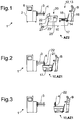
- FIG. 1 shows the handling device 10 in a second working state AZ2.
- the second working state AZ2 there is no operative connection between the receiving and storage unit 20 and the transport means 12, so that the transport means 12 can be arranged and moved independently of the receiving unit 20.
- the transport 12 is inserted from the fourth side under the receptacle 21.
- the transport means 12 is at least partially inserted into the cavity 27 formed below the receptacle 21.
- the height of the horizontal supporting surface 15 of the transport means 12 is adjusted by means of an adjusting means 16 such that the receiving tray 21 at least partially rests on the horizontal bearing surface 15 and thus a Active connection between the transport means 12 and the receiving and bearing unit 20 consists.
- the horizontal support surface 15 is raised even further, so that the receiving and storage unit 20 is additionally raised and no longer stands up on the floor.
- the receiving and storage unit 20 can now be easily moved together with the transport 12.
- FIG. 2 shows the arrangement of a handling device 10 on a stirred ball mill 1.
- the handling device 10 is positioned such that the container bottom 4 is held by the receiving means 22.
- the user B can now solve the fixation of the container bottom 4 and remove it by driving away the handling device 10 from the grinding container 3 of the agitator ball mill 1 (see FIG. 3 ).
- the case emerging from the grinding container 3 grinding media are collected in the receptacle 21.
- the grinding container 3 or the container bottom 4 has an outlet opening (not shown) for discharging the grinding bodies, which are opened before the removal of the container bottom 4 and the grinding media controlled from the grinding container 3 are discharged.
- both the two parallel downwardly extended side boundaries 25 connect connecting transverse boundaries 28, 28 * (see FIGS. 8 and 11 ) each at least partially downwards with the bottom 26 of the receptacle 21 from.
- the opposite openings of the cavity 27 are formed and the transport means 12 can be inserted both from the side of the third transverse boundary 28 ago as well as from the side of the fourth transverse boundary 28 * forth in the cavity 27 below the receptacle 21 of the receiving and storage unit 20 ,
- the downwardly extended side boundaries 25 are arranged obliquely to each other and / or have a curved shape or the like, that is, the side boundaries 25 need not necessarily be arranged parallel to each other.
- the user B shifts the handling device 10 with the container bottom 4 arranged thereon into a work area at which sufficient space is available for the handling device 10 to be able to rotate. Subsequently, it lowers the horizontal support surface 15 of the transport means 12 by means of the scissor lift mechanism 17 and moves the transport means 12 under the receptacle 21 of the receiving and bearing unit 20 out. Now the user B moves the transport means 12 from the opposite side under the receptacle 21 of the receiving and storage unit 20 and provides according FIG. 5 via the scissor lift mechanism 17, the operative connection between the receiving and bearing unit 20 and the transport means 12 by restoring the receptacle 21 on the horizontal support surface 15 ago, so that the handling device 10 now occupies an alternative first working state AZ1 *.
- receiving means 23 are provided for the grinding container 3.
- receiving means 23 are arranged for the grinding container 3 for this step by the user in the receptacle 21.
- the handling device 10 is according to FIG. 5 now positioned by the user B on the agitator ball mill 1 that the grinding container 3 is held by the receiving means 23 in the receptacle 21. Subsequently, the user B can solve the fixations of the grinding container 3 on the agitator ball mill 1 and this according to FIG. 6 by removing the handling device 10, so that the stirring shaft 5 is exposed.
- the user B moves the handling device 10 to a suitable storage position and releases the operative connection between the transporting means 12 and the receiving and storage unit 20.
- the receiving and storage unit 20 remains at the storage position.
- the user now positions accordingly FIG. 7 To take the agitator shaft 5 and safely positioned by the receiving means 24 on the horizontal support surface 15 of the transport means 12, this is - as in FIG. 7 shown - brought about the scissor lift mechanism 17 in a suitable height.
- FIG. 8 shows a perspective view of a handling device 10 according to the invention in a second working state AZ2, in which the physical operative connection between the receiving and storage unit 20 and the transport means 12 is repealed (see FIGS. 1 and 4 ).
- the receiving and storage unit 20 comprises a receiving tray 21 with a receiving means 22 for a container bottom (not shown) of a stirred ball mill 1 (cf. FIGS. 1 to 7 ).
- the receiving means 22 is inserted or placed only in the receptacle 21 (see also FIGS. 10 and 11 ).
- the position of the receiving means 22 can be adapted to the respectively to be serviced agitator ball mill or the receiving means 22 can be replaced accordingly against another suitable receiving means 22 *.
- receiving means 23 for the grinding container are shown. These are also preferably used only in the receptacle 21 and placed and thus positionally variable. Furthermore, the receiving means 23 can be easily removed when it is not needed (see also FIGS. 10 and 11 ). Furthermore, it is shown that two parallel lateral boundaries 25 of the receiving trough 21 are extended below a bottom surface 26 of the receiving trough 21, while connecting transverse surfaces 28 each terminate substantially with the bottom surface 26. This results below the bottom surface 26, a cavity 27 and below the transverse surfaces 28 results in each case an opening through which the transport means 12 can be at least partially inserted into the cavity 27 under the receptacle 21 of the receiving and storage unit 20.
- the receiving means 22, 22 *, 23 can be fixed in each case by suitable securing means, for example by a screw or the like in or on the receptacle 21, thus slipping during transport of container bottom 4 and / or grinding container 3 prevent.
- Stand 29 are still provided on the receiving and storage unit 20. These can each be adjustable in height. Thus, for example, a secure state of the receiving and storage unit 20 can be made possible on an uneven surface.
- the receptacle 21 comparable to a table on four legs, so that the transport means 12 can be inserted between the legs of the receiving and bearing unit 20.
- the transport means 12 is a scissor lift truck 13 with wheels 14 and with an upper horizontal support surface 15.
- the scissor lift mechanism not visible in the illustration can be adjusted via an adjustment means 16.
- the horizontal support surface 15 can be positioned at different heights.
- fixing means 18 are arranged on the wheels.
- the transport means 12 or the handling device 10 can be secured in the first working state AZ1 at a desired location from an undesired process.
- FIGS. 9 to 11 show various perspective views of a handling device 10 according to the invention in a first working state AZ1. It is based on the description of FIGS. 1 to 8 Referenced.
- the receiving means 22, 23 away from the receptacle 21, for example, to clean the receiving means 22, 23 and / or the receptacle 21 can.
- the receptacle 22 does not form a flat surface, but has formed a receiving channel 30.
- the receiving channel is inclined along its longitudinal axis L30 in the direction of a drain 31.
- the process is closed by a closure means 32, for example by means of a screw cap.
- the closure means is arranged on a transverse boundary 28 *, which connects the two lateral boundaries 25 with each other.
- the outlet 31 is opened and the grinding media can be rinsed out, for example with water or another suitable means, and collected in a suitable collecting vessel.
Landscapes
- Engineering & Computer Science (AREA)
- Food Science & Technology (AREA)
- Transportation (AREA)
- Structural Engineering (AREA)
- Mechanical Engineering (AREA)
- Civil Engineering (AREA)
- Life Sciences & Earth Sciences (AREA)
- Geology (AREA)
- Chemical & Material Sciences (AREA)
- Combustion & Propulsion (AREA)
- Crushing And Grinding (AREA)
Description
- Die vorliegende Erfindung betrifft eine Handhabungsvorrichtung zur Wartung von Rührwerkskugelmühlen und ein Verfahren zum Warten einer Rührwerkskugelmühle gemäß den Merkmalen der Oberbegriffe der Ansprüche 1 und 13.
- Die Erfindung betrifft die erleichterte Wartung von Rührwerkskugelmühlen mit einem liegend angeordneten Mahlbehälter.
- Eine derartige Vorrichtung ist aus der
US3542300 bekannt. - Im Rahmen eines Produktwechsels ist beispielsweise ein Austausch der Mahlkörper erforderlich, da die Größe der Mahlkörper auf das jeweils zu vermahlende Produkt abgestimmt ist. Weiterhin kann es notwendig sein, den Boden des Mahlbehälters zu lösen und anschließend den Mahlbehälter komplett von der Rührwelle abnehmen zu müssen, um an dieser beispielsweise Wartungsarbeiten durchzuführen. In der Regel ist es nur bei kleinen Labormühlen für den Benutzer einfach möglich, den Mahlbehälterboden zu lösen und den Mahlbehälterboden und den Mahlbehälter abzunehmen. Bei größeren Mühlen sind insbesondere das Gewicht von Mahlbehälterboden und Mahlbehälter problematisch.
- Aus dem Stand der Technik ist daher die Verwendung von Hilfs- Gestellen zum Transport von Teilen der Rührwerkskugelmühle bekannt, die insbesondere über Räder beweglich sind. Der Benutzer löst zuerst den Mahlbehälterboden, legt diesen auf einem ersten beweglichen Hilfs- Gestell ab und fährt dieses zu einem Lagerplatz. Anschließend verwendet der Benutzer ein zweites Hilfs- Gestell, um den demontierten Mahlbehälter an einen Lagerplatz zu transportieren. Oder aber der Benutzer legt den Mahlbehälterboden am Lagerplatz ab und verwendet das erste Hilfs- Gestell, um nunmehr den Mahlbehälter der Rührwerkskugelmühle abzunehmen und extern zu lagern.
- Zum Auffangen der Mahlkörper, die beispielsweise über den Produktauslass des Mahlbehälters abgelassen werden, sind aus dem Stand der Technik Mahlkörperrutschen und Mahlkörperauffangwannen bekannt.
- Die Aufgabe der Erfindung besteht darin, eine Handhabungsvorrichtung zur Erleichterung der Wartung von Rührwerkskugelmühlen bereitzustellen.
- Die obige Aufgabe wird durch eine Handhabungsvorrichtung und ein Verfahren zum Warten einer Rührwerkskugelmühle gelöst, die die Merkmale in den Patentansprüchen 1 und 12 umfassen. Weitere vorteilhafte Ausgestaltungen werden durch die Unteransprüche beschrieben.
- Die Erfindung betrifft eine Handhabungsvorrichtung zur Wartung von Rührwerkskugelmühlen mit einem liegend angeordneten Mahlbehälter. Insbesondere weist der Mahlbehälter eine zylindrische oder konische Form auf. Die Handhabungsvorrichtung ist insbesondere dafür vorgesehen, dem Benutzer die Demontage und Montage der Rührwerkskugelmühle und gegebenenfalls die Zwischenlagerung von Maschinenteilen der Rührwerkskugelmühle zu erleichtern.
- Zu diesem Zweck umfasst die Handhabungsvorrichtung ein Transportmittel, um die Handhabungsvorrichtung einfach an geeigneten Arbeits- und / oder Lagerplätzen positionieren zu können. Weiterhin umfasst die Handhabungsvorrichtung mindestens eine Aufnahmeeinheit für Maschinenteile der Rührwerkskugelmühle. Das Transportmittel ist lösbar mit der Aufnahmeeinheit verbunden, so dass die Aufnahmeeinheit und das Transportmittel nach Bedarf auch einzeln genutzt werden können.
- Gemäß einer besonders bevorzugten Ausführungsform der Erfindung ist vorgesehen, dass in einem ersten Arbeitszustand der Handhabungsvorrichtung eine Wirkverbindung zwischen der Aufnahmeeinheit und dem Transportmittel ausgebildet ist. Insbesondere ist dabei die Aufnahmeeinheit derart am Transportmittel angeordnet, dass die Aufnahmeeinheit und das Transportmittel gemeinsam beweglich sind.
- Weiterhin kann die Handhabungsvorrichtung einen zweiten Arbeitszustand einnehmen, in dem die Wirkverbindung zwischen der Aufnahmeeinheit und dem Transportmittel gelöst ist, so dass das Transportmittel unabhängig von der Aufnahmeeinheit bewegt werden kann.
- Gemäß der Erfindung ist vorgesehen, dass die Aufnahmeeinheit mindestens eine Aufnahmevorrichtung für mindestens ein Maschinenteil der Rührwerkskugelmühle umfasst. Beispielsweise kann es sich hierbei um eine erste Aufnahmevorrichtung für den Mahlbehälterdeckel beziehungsweise Mahlbehälterboden der Rührwerkskugelmühle handeln.
- Insbesondere kann vorgesehen sein, dass die Handhabungsvorrichtung derart an der Rührwerkskugelmühle positioniert wird, dass der Mahlbehälterdeckel beziehungsweise Mahlbehälterboden durch die erste Aufnahmevorrichtung der Handhabungsvorrichtung gehalten wird. Nach Lösen von Befestigungsmitteln kann der Mahlbehälterdeckel beziehungsweise Mahlbehälterboden leicht vom Mahlbehälter abgenommen werden, indem die Handhabungsvorrichtung mit dem gelösten Mahlbehälterdeckel beziehungsweise Mahlbehälterboden von der Rührwerkskugelmühle entfernt und in eine neue Position verfahren wird.
- Ferner ist eine zweite Aufnahmevorrichtung für den Mahlbehälter der Rührwerkskugelmühle vorgesehen. Die zweite Aufnahmevorrichtung ist als Auflage ausgebildet, auf die der Mahlbehälter aufliegt und die ein Wegrollen des Mahlbehälters verhindert.
- Ferner ist eine dritte Aufnahmevorrichtung insbesondere als oben offener Kasten, beziehungsweise Aufnahmewanne, für die Mahlkörper ausgebildet. Bei der Wartung einer Rührwerkskugelmühle, beispielsweise bei der Wartung der Rührwelle, müssen der Mahlbehälterboden und der Mahlbehälter entfernt werden. Die im Mahlbehälter befindlichen Mahlkörper müssen im Zuge der Demontage aus dem Mahlbehälter abgelassen und gesammelt werden, wofür die Aufnahmewanne vorgesehen ist.
- Gemäß der Erfindung sind die erste und / oder die zweite Aufnahmevorrichtung in und / oder auf der Aufnahmewanne angeordnet. Besonders bevorzugt sind die erste und / oder die zweite Aufnahmevorrichtung lose oder lösbar angeordnet, so dass die Position der ersten und / oder zweiten Aufnahmevorrichtung an die jeweilige Rührwerkskugelmühle, insbesondere an die Größe des Mahlbehälters der Rührwerkskugelmühle, angepasst werden kann. Gegebenenfalls kann es auch vorgesehen sein, für unterschiedlich große Mahlbehälter auch unterschiedliche Aufnahmevorrichtungen vorzusehen.
- In diesem Zusammenhang ist es denkbar, die Aufnahmewanne als ausziehbare Wanne zu gestalten, so dass die Größe einer Horizontalfläche der dritten Aufnahmevorrichtung ebenfalls an die Größe des Mahlbehälters angepasst werden kann.
- Gemäß einer Ausführungsform der Erfindung ist vorgesehen, dass das Transportmittel der Handhabungsvorrichtung höhenverstellbar ist. Insbesondere umfasst das Transportmittel eine Horizontalebene, wobei die Höhe beziehungsweise Vertikalposition der Horizontalebene variabel eingestellt werden kann. Eine stufenlose Einstellung ist beispielsweise über einen Scherenhubmechanismus möglich. Gemäß einer bevorzugten Ausführungsform ist das Transportmittel als Scherenhubtisch mit Transportrollen ausgebildet.
- Gemäß einer Ausführungsform der Erfindung ist vorgesehen, dass das Transportmittel für sich genommen, das heißt ohne Wirkverbindung mit der Aufnahmeeinheit, für die Aufnahme und / oder den Transport und / oder der Zwischenlagerung von mindestens einem weiteren Maschinenteil der Rührwerkskugelmühle dienen kann. Beispielsweise kann nach Bedarf auf der Horizontalebene des Transportmittels mindestens eine Aufnahmevorrichtung für die Rührwelle der Rührwerkskugelmühle angeordnet werden.
- Gemäß einer Ausführungsform der Erfindung sitzt die Aufnahmeeinheit in dem ersten Arbeitszustand zumindest teilweise auf der Horizontalebene des Transportmittels auf. Vorzugsweise sitzt die Aufnahmewanne auf der Horizontalebene des Transportmittels auf. Dadurch wird insbesondere die Wirkverbindung zwischen Aufnahmeeinheit und Transportmittel hergestellt. Durch eine Höhenverstellung des Transportmittels kann zudem die Höhe der Aufnahmeeinheit im ersten Arbeitszustand an die benötigte Arbeitshöhe zur Montage oder Demontage von Maschinenteilen der Rührwerkskugelmühle angepasst werden.
- In einem zweiten Arbeitszustand ist die Höhe der horizontalen Auflagefläche des Transportmittels dagegen derart eingestellt, dass ein Abstand zwischen der Horizontalebene des Transportmittels und der Aufnahmeeinheit ausgebildet ist. In dem zweiten Arbeitszustand ist die Aufnahmeeinheit unbeweglich ausgebildet. Das heißt, in dem zweiten Arbeitszustand ist die Aufnahmeeinheit der Handhabungsvorrichtung ortsfest an der jeweiligen Position angeordnet. Dagegen kann das Transportmittel in dem zweiten Arbeitszustand unabhängig von der Aufnahmeeinheit verfahren werden. Insbesondere ist es möglich, das Transportmittel mittels der Transportrollen an unterschiedliche Positionen an der Rührwerkskugelmühle zu verfahren oder von der Rührwerkskugelmühle zu entfernen.
- Die Erfindung betrifft weiterhin ein Verfahren zum Warten einer Rührwerkskugelmühle unter Verwendung einer vorbeschriebenen Handhabungsvorrichtung. Gemäß einer Ausführungsform der Erfindung ist vorgesehen, mindestens ein Maschinenteil der Rührwerkskugelmühle an der Aufnahmeeinheit anzuordnen und an einer Lagerposition zu positionieren und anschließend mindestens ein weiteres Maschinenteil an dem von der Aufnahmeeinheit gelösten Transportmittel anzuordnen.
- Beispielsweise wird bei der Demontage einer Rührwerkskugelmühle im Rahmen von Wartungsarbeiten mit Hilfe der Handhabungsvorrichtung folgendermaßen vorgegangen: Die Handhabungsvorrichtung wird an der Rührwerkskugelmühle positioniert, so dass die dritte Aufnahmevorrichtung, insbesondere die Aufnahmewanne für die Mahlkörper unterhalb des Mahlbehälters angeordnet ist. Nun wird beispielsweise ein Grobauslass am Mahlbehälter geöffnet und die innerhalb des Mahlbehälters befindlichen Mahlkörper werden abgelassen.
- Anschließend wird die Handhabungsvorrichtung derart an die Rührwerkskugelmühle herangeschoben, dass der Mahlbehälterboden durch die erste Aufnahmevorrichtung gehalten wird. Gegebenenfalls wird über den Höhenverstellmechanismus des Transportmittels auch die Höhe der Aufnahmeeinheit entsprechend angepasst.
- Beispielsweise kann die erste Aufnahmevorrichtung geeignete Aufnahmen umfassen, in die Teile des Mahlbehälterbodens eingreifen oder ähnliches. Die Befestigungsmittel zur Fixierung des Mahlbehälterbodens am Mahlbehälter werden vom Benutzer gelöst. Anschließend wird die Handhabungsvorrichtung zumindest so weit von der Rührwerkskugelmühle weg verfahren, dass der Mahlbehälterboden vom Mahlbehälter abgenommen ist.
- Nunmehr kann auf oder in der dritten Aufnahmevorrichtung eine zweite Aufnahmevorrichtung zur Positionierung und / oder Fixierung des Mahlbehälters angeordnet und die Handhabungsvorrichtung wiederum so unterhalb des Mahlbehälters positioniert werden, dass die erste Aufnahmevorrichtung von unten an den Mahlbehälter gehoben werden kann, so dass dieser darauf aufliegt. Nun werden die Befestigungsmittel zur Fixierung des Mahlbehälters gelöst. Durch Wegfahren der Handhabungsvorrichtung wird nunmehr der Mahlbehälter von der Rührwerkskugelmühle abgenommen. Die Handhabungsvorrichtung kann nun durch den Benutzer an einem geeigneten Zwischenlagerplatz positioniert werden.
- Durch Absenken der horizontalen Auflagefläche des Transportmittels wird die Wirkverbindung zwischen dem Transportmittel und der Aufnahmeeinheit gelöst. Während die Aufnahmeeinheit nunmehr ortsfest an dem Zwischenlagerplatz angeordnet ist, kann das Transportmittel erneut an der Rührwerkskugelmühle positioniert werden.
- Um die Rührwelle abzunehmen, wird die horizontale Auflagefläche des Transportmittels auf eine geeignete Höhe gebracht und es kann beispielsweise eine geeignete vierte Aufnahmevorrichtung auf der horizontalen Auflagefläche des Transportmittels angeordnet werden. Die vierte Aufnahmevorrichtung ist dergestalt ausgebildet, dass die Rührwelle auf der horizontalen Auflagefläche zumindest teilweise fixiert ist, insbesondere verhindert die vierte Aufnahmevorrichtung ein Wegrollen der Rührwelle auf der horizontalen Auflagefläche. Nach Lösen der Befestigungsmittel zur Fixierung der Rührwelle kann diese nun durch Verfahren des Transportmittels von der Rührwerkskugelmühle abgenommen werden.
- Das Verfahren kann alternativ oder zusätzlich zu den beschriebenen Merkmalen ein oder mehrere Merkmale und / oder Eigenschaften der zuvor beschriebenen Vorrichtung umfassen. Ebenfalls kann die Vorrichtung alternativ oder zusätzlich einzelne oder mehrere Merkmale und / oder Eigenschaften des beschriebenen Verfahrens aufweisen.
- Die erfindungsgemäße Handhabungsvorrichtung erleichtert insbesondere den Umgang mit Maschinenteilen einer Rührwerkskugelmühle und / oder mit den in einer Rührwerkskugelmühle verwendeten Mahlkörpern. Insbesondere erlaubt die Handhabungsvorrichtung dem Benutzer eine erleichterte Demontage einer Mehrzahl von schweren Maschinenbauteilen der Rührwerkskugelmühle mit einer einzigen Hilfseinrichtung.
- Im Folgenden sollen Ausführungsbeispiele die Erfindung und ihre Vorteile anhand der beigefügten Figuren näher erläutern. Die Größenverhältnisse der einzelnen Elemente zueinander in den Figuren entsprechen nicht immer den realen Größenverhältnissen, da einige Formen vereinfacht und andere Formen zur besseren Veranschaulichung vergrößert im Verhältnis zu anderen Elementen dargestellt sind.
-
Figuren 1 bis 7 zeigen die Verwendung einer erfindungsgemäßen Handhabungsvorrichtung bei der Wartung einer Rührwerkskugelmühle. -
Figur 8 zeigt eine perspektivische Darstellung einer erfindungsgemäßen Handhabungsvorrichtung in einem zweiten Arbeitszustand. -
Figuren 9 bis 11 zeigen verschiedene perspektivische Darstellungen einer erfindungsgemäßen Handhabungsvorrichtung in einem ersten Arbeitszustand. - Für gleiche oder gleich wirkende Elemente der Erfindung werden identische Bezugszeichen verwendet. Ferner werden der Übersicht halber nur Bezugszeichen in den einzelnen Figuren dargestellt, die für die Beschreibung der jeweiligen Figur erforderlich sind. Die dargestellten Ausführungsformen stellen lediglich Beispiele dar, wie die erfindungsgemäße Vorrichtung oder das erfindungsgemäße Verfahren ausgestaltet sein können und stellen keine abschließende Begrenzung dar.
-
Figuren 1 bis 7 zeigen die Verwendung einer erfindungsgemäßen Handhabungsvorrichtung 10 bei der Wartung einer Rührwerkskugelmühle 1, insbesondere bei der zumindest teilweisen Demontage einer Rührwerkskugelmühle 1, beispielsweise im Rahmen einer Reparatur oder ähnlichem. Die Rührwerkskugelmühle 1 umfasst ein Maschinengehäuse 2, in dem der Antrieb der Rührwerkskugelmühle 1 (nicht dargestellt), die Maschinensteuerung und weitere Maschinenkomponenten angeordnet sind. Beispielsweise ist am Maschinengehäuse 2 ein Bedienpult 6 vorgesehen, über das die Rührwerkskugelmühle 1 gesteuert werden kann. - Die Rührwerkskugelmühle 1 umfasst weiterhin einen Mahlbehälter 3, in dem der Mahlprozess stattfindet. Der Mahlbehälter 3 ist zylindrisch ausgebildet und liegend angeordnet, wobei ein Ende des Mahlbehälters 3 in verschiedenen Stellungen bzw. Ausrichtungen am Maschinengehäuse 2 befestigt werden kann. Das gegenüberliegende freie Ende des Mahlbehälters 3, an dem sich in der Regel der Produktauslass befindet, ist mit einem Behälterboden 4 verschlossen. Um beispielsweise Wartungsarbeiten an der Rührwelle 5 (vergleiche
Figuren 6 und7 ) der Rührwerkskugelmühle 1 durchzuführen, muss zuerst der Behälterboden 4 und anschließend der Mahlbehälter 3 von dem Maschinengehäuse 2 der Rührwerkskugelmühle 1 gelöst und abgenommen werden. - Um die Handhabung von Behälterboden 4, Mahlbehälter 3 und Rührwelle 5 für den Benutzer B zu erleichtern, ist eine Handhabungsvorrichtung 10 vorgesehen. Diese besteht im Wesentlichen aus zwei Funktionseinheiten, insbesondere einem Transportmittel 12 und einer Aufnahme- und Lagereinheit 20, die in den
Figuren 1 ,4 ,7 und 8 jeweils einzeln dargestellt sind. DieFiguren 2, 3 ,5, 6 und9 bis 11 zeigen dagegen die Handhabungsvorrichtung 10, wobei die Aufnahme- und Lagereinheit 20 lösbar an dem Transportmittel 12 angeordnet ist. - Das Transportmittel 12 ist beispielsweise eine Art Scherenhubwagen 13 mit Rädern 14 und mit einer oberen horizontalen Auflagefläche 15. Weiterhin ist mindestens ein Einstellmittel 16 zur Betätigung und Einstellung des Scherenhubmechanismus 17 vorgesehen. Über das Einstellmittel 16 kann vermittels des Scherenhubmechanismus 17 ein beliebiges Vertikalniveau der horizontalen Auflagefläche 15 eingestellt werden, das heißt die horizontale Auflagefläche 15 kann in unterschiedlichen Höhen positioniert werden.
- Die Aufnahme- und Lagereinheit 20 umfasst eine obere Aufnahmewanne 21, insbesondere zur Aufnahme von aus der Rührwerkskugelmühle 1 abgelassenen Mahlkörpern, weiterhin umfasst die Aufnahme- und Lagereinheit 20 im dargestellten Ausführungsbeispiel ein erstes Aufnahmemittel 22 für den Behälterboden 4 der Rührwerkskugelmühle 1 und ein zweites Aufnahmemittel 23 für den Mahlbehälter 3 der Rührwerkskugelmühle 1. Zwei parallele seitlichen Begrenzungen 25 der Aufnahmewanne 21 ragen nach unten über den Boden 26 der Aufnahmewanne 21 hinaus, so dass unterhalb der Aufnahmewanne 21 ein Hohlraum 27 (vergleiche
Figur 8 ) ausgebildet ist. Eine zwischen den parallelen seitlichen Begrenzungen angeordnete dritte Querbegrenzung der Aufnahmewanne 21 kann ebenfalls nach unten über den Boden 26 der Aufnahmewanne 21 hinausragend ausgebildet sein. Dagegen schließt einer vierte Querbegrenzung der Aufnahmewanne 21 zumindest bereichsweise nach unten mit dem Boden 26 der Aufnahmewanne 21 ab. Vorzugsweise schließen sowohl die dritte als auch die vierte Querbegrenzung 28, 28* (vergleicheFiguren 8 und11 ) zumindest bereichsweise nach unten mit dem Boden 26 der Aufnahmewanne 21 ab. Durch die verlängerten seitlichen Begrenzungen 25 in Kombination mit mindestens einer verkürzten Querbegrenzung 28, 28* (vergleicheFiguren 8 und11 ) wird unterhalb der Aufnahmewanne 21 ein Hohlraum 27 ausgebildet, der zumindest eine, vorzugsweise zwei einander gegenüberliegende, seitliche Öffnungen aufweist. - Vorzugsweise ragen die zwei parallelen Seitenbegrenzungen und gegebenenfalls die dritte Querbegrenzung jeweils gleich nach unten über den Boden hinaus und bilden somit Standmittel. Alternativ und / oder zusätzlich kann die Verwendung von Füßen an den Schnittpunkten zwischen den parallelen Seitenbegrenzungen und der dritten Querbegrenzung bzw. dem Bereich der vierten Seitenbegrenzung vorteilhaft sein.
-
Figur 1 zeigt die Handhabungsvorrichtung 10 in einem zweiten Arbeitszustand AZ2. In dem zweiten Arbeitszustand AZ2 besteht keine Wirkverbindung zwischen der Aufnahme- und Lagereinheit 20 und dem Transportmittel 12, so dass das Transportmittel 12 unabhängig von der Aufnahmeeinheit 20 angeordnet und bewegt werden kann. - Das Transportmittel 12 wird von der vierten Seite her unter die Aufnahmewanne 21 eingeschoben. Insbesondere wird das Transportmittel 12 zumindest teilweise in den unterhalb der Aufnahmewanne 21 ausgebildeten Hohlraum 27 eingeschoben. Anschließend wird die Höhe der horizontalen Auflagefläche 15 des Transportmittels 12 mit Hilfe eines Einstellmittels 16 derart eingestellt, dass die Aufnahmewanne 21 zumindest bereichsweise auf der horizontalen Auflagefläche 15 aufliegt und somit eine Wirkverbindung zwischen dem Transportmittel 12 und der Aufnahme- und Lagereinheit 20 besteht. Dies stellt den ersten Arbeitszustand AZ1 der Handhabungsvorrichtung 10 dar, wie es beispielsweise in den
Figuren 2 und 3 dargestellt ist. Vorzugsweise wird die horizontale Auflagefläche 15 noch weiter angehoben, so dass die Aufnahme- und Lagereinheit 20 zusätzlich angehoben wird und nicht mehr auf dem Boden aufsteht. Die Aufnahme- und Lagereinheit 20 kann nun zusammen mit dem Transportmittel 12 problemlos verschoben werden. -
Figur 2 zeigt die Anordnung einer Handhabungsvorrichtung 10 an einer Rührwerkskugelmühle 1. Die Handhabungsvorrichtung 10 wird derart positioniert, dass der Behälterboden 4 durch die Aufnahmemittel 22 gehalten wird. Hierzu kann es notwendig sein, die Aufnahme- und Lagereinheit 20 über einen Scherenhubmechanismus 17 des Transportmittels in einer geeigneten Höhe zu positionieren. Der Benutzer B kann nunmehr die Fixierung des Behälterbodens 4 lösen und diesen durch Wegfahren der Handhabungsvorrichtung 10 vom Mahlbehälter 3 der Rührwerkskugelmühle 1 abnehmen (vergleicheFigur 3 ). Die dabei aus dem Mahlbehälter 3 austretenden Mahlkörper werden in der Aufnahmewanne 21 aufgefangen. Alternativ kann vorgesehen sein, dass der Mahlbehälter 3 oder der Behälterboden 4 eine Auslassöffnung (nicht dargestellt) zum Auslassen der Mahlkörper aufweist, die vor dem Entfernen des Behälterbodens 4 geöffnet und die Mahlkörper kontrolliert aus dem Mahlbehälter 3 abgelassen werden. - Gemäß einer in den Figuren dargestellten Ausführungsform schließen beide, die zwei parallelen nach unten verlängerten Seitenbegrenzungen 25 verbindenden Querbegrenzungen 28, 28* (vergleiche
Figuren 8 und11 ) jeweils zumindest bereichsweise nach unten mit dem Boden 26 der Aufnahmewanne 21 ab. Dadurch werden die gegenüberliegenden Öffnungen des Hohlraums 27 gebildet und das Transportmittel 12 kann sowohl von der Seite der dritten Querbegrenzung 28 her als auch von der Seite der vierten Querbegrenzung 28* her in den Hohlraum 27 unterhalb der Aufnahmewanne 21 der Aufnahme- und Lagereinheit 20 eingeschoben werden. - Gemäß einer weiteren (nicht dargestellten Ausführungsform) sind die nach unten verlängerten Seitenbegrenzungen 25 schräg zueinander angeordnet und / oder weisen eine gebogene Form auf oder Ähnliches, das heißt die Seitenbegrenzungen 25 müssen nicht zwingend parallel zueinander angeordnet sein.
- Gemäß
Figur 4 verschiebt der Benutzer B die Handhabungsvorrichtung 10 mit dem darauf angeordneten Behälterboden 4 in einen Arbeitsbereich, an dem ausreichend Platz vorhanden ist, um die Handhabungsvorrichtung 10 drehen zu können. Anschließend senkt er die horizontale Auflagefläche 15 des Transportmittels 12 mit Hilfe des Scherenhubmechanismus 17 ab und fährt das Transportmittel 12 unter der Aufnahmewanne 21 der Aufnahme- und Lagereinheit 20 heraus. Nunmehr fährt der Benutzer B das Transportmittel 12 von der gegenüberliegenden Seite unter die Aufnahmewanne 21 der Aufnahme- und Lagereinheit 20 und stellt gemäßFigur 5 über den Scherenhubmechanismus 17 die Wirkverbindung zwischen der Aufnahme- und Lagereinheit 20 und dem Transportmittel 12 durch Auflage der Aufnahmewanne 21 auf die horizontalen Auflagefläche 15 wieder her, so dass die Handhabungsvorrichtung 10 nunmehr einen alternativen ersten Arbeitszustand AZ1* einnimmt. - Innerhalb der Aufnahmewanne 21 sind weitere Aufnahmemittel 23 (vergleiche
Figur 1 ) für den Mahlbehälter 3 vorgesehen. Alternativ kann vorgesehen sein, dass Aufnahmemittel 23 für den Mahlbehälter 3 für diesen Arbeitsschritt durch den Benutzer in der Aufnahmewanne 21 angeordnet werden. Die Handhabungsvorrichtung 10 wird gemäßFigur 5 nunmehr durch den Benutzer B derart an der Rührwerkskugelmühle 1 positioniert, dass der Mahlbehälter 3 durch die Aufnahmemittel 23 in der Aufnahmewanne 21 gehalten wird. Anschließend kann der Benutzer B die Fixierungen des Mahlbehälters 3 an der Rührwerkskugelmühle 1 lösen und diesen gemäßFigur 6 durch Verfahren der Handhabungsvorrichtung 10 abnehmen, so dass die Rührwelle 5 freiliegt. - Soll in einem weiteren Arbeitsschritt die Rührwelle 5 ebenfalls von der Rührwerkskugelmühle 1 entfernt werden, so verfährt der Benutzer B die Handhabungsvorrichtung 10 an eine geeignete Lagerposition und löst die Wirkverbindung zwischen dem Transportmittel 12 und der Aufnahme- und Lagereinheit 20. Die Aufnahme- und Lagereinheit 20 verbleibt an der Lagerposition. Der Benutzer positioniert nun gemäß
Figur 7 Aufnahmemittel 24 für die Rührwelle 5 auf der horizontalen Auflagefläche 15 des Transportmittels 12. Um die Rührwelle 5 abzunehmen und sicher durch die Aufnahmemitteln 24 auf der horizontalen Auflagefläche 15 des Transportmittels 12 zu positionieren, wird diese - wie inFigur 7 dargestellt - über den Scherenhubmechanismus 17 in eine geeignete Höhe gebracht. -
Figur 8 zeigt eine perspektivische Darstellung einer erfindungsgemäßen Handhabungsvorrichtung 10 in einem zweiten Arbeitszustand AZ2, bei dem die physikalische Wirkverbindung zwischen der Aufnahme- und Lagereinheit 20 und dem Transportmittel 12 aufgehoben ist (vergleicheFiguren 1 und4 ). - Insbesondere ist in der Darstellung erkennbar, dass die Aufnahme- und Lagereinheit 20 eine Aufnahmewanne 21 mit einem Aufnahmemittel 22 für einen Behälterboden (nicht dargestellt) einer Rührwerkskugelmühle 1 (vergleiche
Figuren 1 bis 7 ) umfasst. Beispielsweise ist das Aufnahmemittel 22 nur in die Aufnahmewanne 21 eingesetzt bzw. aufgesetzt (vergleiche auchFiguren 10 und 11 ). Somit kann die Position des Aufnahmemittels 22 an die jeweilig zu wartenden Rührwerkskugelmühle angepasst werden bzw. das Aufnahmemittel 22 kann entsprechend gegen ein anderes geeignetes Aufnahmemittel 22* ausgetauscht werden. - Weiterhin sind Aufnahmemittel 23 für den Mahlbehälter (nicht dargestellt) gezeigt. Diese sind vorzugsweise ebenfalls nur in die Aufnahmewanne 21 eingesetzt bzw. aufgesetzt und somit positionsvariabel. Weiterhin kann das Aufnahmemittel 23 einfach entfernt werden, wenn es nicht benötigt wird (vergleiche auch
Figuren 10 und 11 ). Weiterhin ist dargestellt, dass zwei parallele seitliche Begrenzungen 25 der Aufnahmewanne 21 unterhalb einer Bodenfläche 26 der Aufnahmewanne 21 verlängert sind, während verbindende Querflächen 28 jeweils weitgehend mit der Bodenfläche 26 abschließen. Dadurch ergibt sich unterhalb der Bodenfläche 26 ein Hohlraum 27 und unterhalb der Querflächen 28 ergibt sich jeweils eine Öffnung, über die das Transportmittel 12 zumindest teilweise in den Hohlraum 27 unter die Aufnahmewanne 21 der Aufnahme- und Lagereinheit 20 eingeschoben werden kann. - Alternativ kann vorgesehen sein, dass die Aufnahmemittel 22, 22*, 23 jeweils durch geeignete Sicherungsmittel, beispielsweise durch eine Verschraubung oder ähnlichem in oder an der Aufnahmewanne 21 fixiert werden können, um somit ein Verrutschen beim Transport von Behälterboden 4 und / oder Mahlbehälter 3 zu verhindern.
- Zur Erhöhung der Standfestigkeit der Aufnahme- und Lagereinheit 20 im zweiten Arbeitszustand (vergleiche
Figuren 1 ,4 und7 ) sind an der Aufnahme- und Lagereinheit 20 weiterhin Standfüße 29 vorgesehen. Diese können jeweils in ihrer Höhe justierbar sein. Damit kann beispielsweise ein sicherer Stand der Aufnahme- und Lagereinheit 20 auch auf einem unebenen Untergrund ermöglicht werden. - Alternativ kann vorgesehen sein, die Aufnahmewanne 21 vergleichbar mit einem Tisch auf vier Beinen anzuordnen, so dass das Transportmittel 12 zwischen den Beinen der Aufnahme- und Lagereinheit 20 eingeschoben werden kann.
- Das Transportmittel 12 ist ein Scherenhubwagen 13 mit Rädern 14 und mit einer oberen horizontalen Auflagefläche 15. Der in der Darstellung nicht sichtbare Scherenhubmechanismus kann über ein Einstellmittel 16 eingestellt werden. Insbesondere kann die horizontale Auflagefläche 15 in unterschiedlichen Höhen positioniert werden.
- Weiterhin sind Fixiermittel 18 an den Rädern angeordnet. Damit kann das Transportmittel 12 beziehungsweise die Handhabungsvorrichtung 10 im ersten Arbeitszustand AZ1 an einem gewünschten Standort vor einem ungewünschten Verfahren gesichert werden.
-
Figuren 9 bis 11 zeigen verschiedene perspektivische Darstellungen einer erfindungsgemäßen Handhabungsvorrichtung 10 in einem ersten Arbeitszustand AZ1. Es wird auf die Beschreibung derFiguren 1 bis 8 Bezug genommen. Insbesondere wurden in denFiguren 10 und 11 die Aufnahmemittel 22, 23 von der Aufnahmewanne 21 entfernt, beispielsweise um die Aufnahmemittel 22, 23 und / oder die Aufnahmewanne 21 reinigen zu können. - In den
Figuren 9 bis 11 kann man erkennen, dass die Aufnahmewanne 22 keine ebene Fläche ausbildet, sondern eine Aufnahmerinne 30 ausgebildet hat. Zudem ist die Aufnahmerinne entlang ihrer Längsachse L30 in Richtung eines Ablaufs 31 geneigt. Der Ablauf ist über ein Verschlussmittel 32, beispielsweise vermittels eines Schraubverschluss verschlossen. Vorzugsweise ist das Verschlussmittel an einer Querbegrenzung 28* angeordnet, die die beiden seitlichen Begrenzungen 25 miteinander verbindet. Um die aus dem Mahlbehälter der Rührwerkskugelmühle abgelassenen Mahlkörper aus den Aufnahmewanne 21 zu entfernen, wird der Ablauf 31 geöffnet und die Mahlkörper können beispielsweise mit Wasser oder einem anderen geeigneten Mittel herausgespült und in einem geeigneten Auffangbehälter gesammelt werden. - Die Erfindung wurde unter Bezugnahme auf eine bevorzugte Ausführungsform beschrieben. Es ist jedoch für einen Fachmann vorstellbar, dass Abwandlungen oder Änderungen der Erfindung gemacht werden können, ohne dabei den Schutzbereich der nachstehenden Ansprüche zu verlassen.
-
- 1
- Rührwerkskugelmühle
- 2
- Maschinengehäuse
- 3
- Mahlbehälter
- 4
- Behälterboden
- 5
- Rührwelle
- 6
- Bedienpult
- 10
- Handhabungsvorrichtung
- 12
- Transportmittel
- 13
- Scherenhubwagen
- 14
- Räder
- 15
- horizontale Auflagefläche
- 16
- Einstellmittel
- 17
- Scherenhubmechanismus
- 18
- Fixiermittel
- 20
- Aufnahme- und Lagereinheit
- 21
- Aufnahmewanne
- 22
- Aufnahmemittel für Behälterboden
- 23
- Aufnahmemittel für Mahlbehälter
- 24
- Aufnahmemittel für Rührwelle
- 25
- seitliche Begrenzungen
- 26
- Boden / Bodenfläche
- 27
- Hohlraum
- 28
- Querfläche / Querbegrenzung
- 29
- Standfuß
- 30
- Aufnahmerinne
- 31
- Ablauf
- 32
- Verschlussmittel
- 33
- Schraubverschluss
- AZ
- Arbeitszustand
- B
- Benutzer
Claims (13)
- Handhabungsvorrichtung (10) zur Wartung von Rührwerkskugelmühlen (1) mit einem liegend angeordneten Mahlbehälter (3), wobei die Handhabungsvorrichtung (10) ein Transportmittel (12) und mindestens eine Aufnahmeeinheit (20) für Maschinenteile einer Rührwerkskugelmühle (1) umfasst, wobei das Transportmittel (12) lösbar mit der Aufnahmeeinheit (20) verbunden ist, dadurch gekennzeichnet, dass die Aufnahmeeinheit (20) mindestens eine erste Aufnahmevorrichtung (22) für einen Mahlbehälterdeckel bzw. einen Mahlbehälterboden (4) der Rührwerkskugelmühle (1) und eine zweite Aufnahmevorrichtung (23) für den Mahlbehälter (3) der Rührwerkskugelmühle (1) und eine dritte Aufnahmevorrichtung für Mahlkörper der Rührwerkskugelmühle (1) umfasst, wobei die zweite Aufnahmevorrichtung als Auflage und die dritte Aufnahmevorrichtung durch eine Aufnahmewanne (21) gebildet ist, und wobei die erste Aufnahmevorrichtung (22) und die zweite Aufnahmevorrichtung (23) in und/oder auf der Aufnahmewanne (21) angeordnet sind.
- Handhabungsvorrichtung (10) nach Anspruch 1, in einem ersten Arbeitszustand (AZ1) eine Wirkverbindung zwischen der Aufnahmeeinheit (20) und dem Transportmittel (12) ausgebildet ist, insbesondere wobei in einem ersten Arbeitszustand (AZ1) die Aufnahmeeinheit (20) derart am Transportmittel (12) angeordnet ist, dass die Aufnahmeeinheit (20) und das Transportmittel (12) gemeinsam beweglich sind.
- Handhabungsvorrichtung (10) nach Anspruch 2, wobei in einem zweiten Arbeitszustand (AZ2) die Wirkverbindung zwischen der Aufnahmeeinheit (20) und dem Transportmittel (12) gelöst ist, so dass das Transportmittel (12) unabhängig von der Aufnahmeeinheit (20) beweglich ist.
- Handhabungsvorrichtung (10) nach einem der voranstehenden Ansprüche, wobei das Transportmittel (12) höhenverstellbar ist.
- Handhabungsvorrichtung (10) nach Anspruch 4, wobei das Transportmittel (12) eine Horizontalebene (15) umfasst, wobei die Höhe der Horizontalebene (15) des Transportmittels (12) einstellbar ist.
- Handhabungsvorrichtung (10) nach Anspruch 5, wobei auf der Horizontalebene (15) des Transportmittels (12) Aufnahme- und / oder Positioniermittel (24) für eine Rührwelle (5) der Rührwerkskugelmühle (1) anordenbar sind.
- Handhabungsvorrichtung (10) nach einem der Ansprüche 3 bis 6, wobei mindestens eine Größe der mindestens einen Aufnahmevorrichtung (21) für Mahlkörper der Rührwerkskugelmühle (1) durch eine ausziehbare Aufnahmewanne (21) einstellbar ist, insbesondere wobei die Größe einer Horizontalfläche der Aufnahmevorrichtung (21) einstellbar ist.
- Handhabungsvorrichtung (10) nach Anspruch 5 und 7, wobei die Aufnahmeeinheit (20) in dem ersten Arbeitszustand (AZ1) zumindest teilweise auf der Horizontalebene (15) des Transportmittels (12) aufsitzt.
- Handhabungsvorrichtung (10) nach Anspruch 5, wobei die Aufnahmeeinheit (20) in dem ersten Arbeitszustand (AZ1) durch das Transportmittel (12) in unterschiedlichen Höhen positionierbar ist.
- Handhabungsvorrichtung (10) nach Anspruch 5, wobei in dem zweiten Arbeitszustand (AZ2) ein Abstand zwischen der Horizontalebene (15) des Transportmittels (12) und der Aufnahmeeinheit (20) ausgebildet ist.
- Handhabungsvorrichtung (10) nach Anspruch 5, wobei die Aufnahmeeinheit (20) in dem zweiten Arbeitszustand (AZ2) ortsfest ausgebildet ist und wobei das Transportmittel (12) in dem zweiten Arbeitszustand (AZ2) allein beweglich ausgebildet ist.
- Verfahren zum Warten einer Rührwerkskugelmühle (1) unter Verwendung einer Handhabungsvorrichtung (10) nach einem der voranstehenden Ansprüche.
- Verfahren nach Anspruch 12, wobei mindestens ein Maschinenteil (3, 4) der Rührwerkskugelmühle (1) an der Aufnahmeeinheit (20) der Handhabungsvorrichtung (10) angeordnet wird und wobei mindestens ein weiteres Maschinenteil (5) der Rührwerkskugelmühle (1) an dem von der Aufnahmeeinheit (20) gelösten Transportmittel (12) angeordnet wird.
Priority Applications (1)
| Application Number | Priority Date | Filing Date | Title |
|---|---|---|---|
| PL16000346T PL3075452T3 (pl) | 2015-04-02 | 2016-02-11 | Urządzenie manipulacyjne do konserwacji mieszadłowych młynów perełkowych oraz sposób konserwacji mieszadłowego młyna perełkowego |
Applications Claiming Priority (1)
| Application Number | Priority Date | Filing Date | Title |
|---|---|---|---|
| DE102015105104.4A DE102015105104A1 (de) | 2015-04-02 | 2015-04-02 | Handhabungsvorrichtung zur Wartung von Rührwerkskugelmühlen und Verfahren zum Warten einer Rührwerkskugelmühle |
Publications (2)
| Publication Number | Publication Date |
|---|---|
| EP3075452A1 EP3075452A1 (de) | 2016-10-05 |
| EP3075452B1 true EP3075452B1 (de) | 2019-03-27 |
Family
ID=55361311
Family Applications (1)
| Application Number | Title | Priority Date | Filing Date |
|---|---|---|---|
| EP16000346.3A Active EP3075452B1 (de) | 2015-04-02 | 2016-02-11 | Handhabungsvorrichtung zur wartung von rührwerkskugelmühlen und verfahren zum warten einer rührwerkskugelmühle |
Country Status (7)
| Country | Link |
|---|---|
| US (1) | US10000224B2 (de) |
| EP (1) | EP3075452B1 (de) |
| CN (1) | CN106040373B (de) |
| BR (1) | BR102016006448B1 (de) |
| DE (1) | DE102015105104A1 (de) |
| ES (1) | ES2728731T3 (de) |
| PL (1) | PL3075452T3 (de) |
Families Citing this family (1)
| Publication number | Priority date | Publication date | Assignee | Title |
|---|---|---|---|---|
| DE102017119421A1 (de) * | 2017-08-24 | 2019-02-28 | Linde Material Handling Gmbh | Autonomes Flurförderzeug, insbesondere Kommissionier-Flurförderzeug |
Family Cites Families (16)
| Publication number | Priority date | Publication date | Assignee | Title |
|---|---|---|---|---|
| US3180581A (en) * | 1962-07-19 | 1965-04-27 | Reserve Mining Co | Ball mill discharge trommel |
| GB1216191A (en) * | 1967-01-05 | 1970-12-16 | Foster Wheeler Brown Boilers | Improvements in and relating to pulverising mills |
| US3545687A (en) * | 1968-06-27 | 1970-12-08 | Martin Marietta Corp | Media mill |
| MX143274A (es) * | 1975-05-01 | 1981-04-13 | Morehouse Ind Inc | Mejoras en aparato para moler particulas dentro de un liquido |
| US4809915A (en) * | 1988-03-07 | 1989-03-07 | Affald International Inc. | Waste disposal apparatus |
| US5454625A (en) * | 1994-04-18 | 1995-10-03 | Kloppenburg & Co. | Ice cart |
| DE4419509C2 (de) * | 1994-06-03 | 2003-04-30 | Hosokawa Alpine Ag & Co | Maschinengestell mit Hubeinrichtung |
| US5788251A (en) * | 1994-07-12 | 1998-08-04 | Johnson; Rudolph O. | Table lift and transporter |
| DE19913243A1 (de) * | 1999-03-24 | 2000-10-12 | Zoz Maschinenbau Gmbh | Mahlvorrichtung zur Hochenergie- und/oder Feinstmahlung von Feststoffen mit schwenkbarem Mahlbehälter |
| US6431319B1 (en) * | 2000-02-29 | 2002-08-13 | Ferno-Washington, Inc. | Height-adjustable equipment cart with detachable table |
| US7188843B2 (en) * | 2000-08-29 | 2007-03-13 | Annop Magness | Multiuse lifting and rolling platform |
| DE20202204U1 (de) * | 2002-02-14 | 2003-03-27 | Metallbau Waldemar Hoesl | Montagewagen |
| US6726416B2 (en) * | 2002-05-23 | 2004-04-27 | Griswold Machine & Engineering, Inc. | Die storage container |
| US7165776B2 (en) * | 2003-05-22 | 2007-01-23 | Crown Equipment Corporation | Pivotable tray for a pallet truck |
| CN201427544Y (zh) * | 2009-04-15 | 2010-03-24 | 济南重工股份有限公司 | 筒式湿式球磨机发运装置 |
| DE202009005644U1 (de) * | 2009-04-17 | 2009-09-10 | Bär, Ralf, Dipl.-Ing. | Fahrerloser Montagewagen für eine Montagelinie mit Arbeitsstationen |
-
2015
- 2015-04-02 DE DE102015105104.4A patent/DE102015105104A1/de not_active Ceased
- 2015-11-05 CN CN201510744959.0A patent/CN106040373B/zh active Active
-
2016
- 2016-02-11 ES ES16000346T patent/ES2728731T3/es active Active
- 2016-02-11 EP EP16000346.3A patent/EP3075452B1/de active Active
- 2016-02-11 PL PL16000346T patent/PL3075452T3/pl unknown
- 2016-02-23 US US15/051,141 patent/US10000224B2/en active Active
- 2016-03-23 BR BR102016006448-1A patent/BR102016006448B1/pt active IP Right Grant
Non-Patent Citations (1)
| Title |
|---|
| None * |
Also Published As
| Publication number | Publication date |
|---|---|
| DE102015105104A1 (de) | 2016-10-06 |
| PL3075452T3 (pl) | 2019-09-30 |
| ES2728731T3 (es) | 2019-10-28 |
| EP3075452A1 (de) | 2016-10-05 |
| CN106040373A (zh) | 2016-10-26 |
| BR102016006448A2 (pt) | 2016-10-25 |
| BR102016006448B1 (pt) | 2021-05-25 |
| CN106040373B (zh) | 2019-07-05 |
| US20160288810A1 (en) | 2016-10-06 |
| US10000224B2 (en) | 2018-06-19 |
Similar Documents
| Publication | Publication Date | Title |
|---|---|---|
| EP2881187B1 (de) | Walzenrichtmaschine sowie Verfahren zum Inspizieren, Warten und Instandhalten einer Walzenrichtmaschine | |
| DE102013213716B4 (de) | Vorrichtung und Verfahren zum Anheben einer Pfanne | |
| EP3293393A1 (de) | Vorrichtung und verfahren zum austausch von austauschbaren komponenten einer windenergieanlage | |
| EP3075452B1 (de) | Handhabungsvorrichtung zur wartung von rührwerkskugelmühlen und verfahren zum warten einer rührwerkskugelmühle | |
| EP2562477B1 (de) | Entschlacker zur Austragung von Verbrennungsrückständen einer Verbrennungsanlage | |
| DE102013213718B3 (de) | Vorrichtung zum Anheben und wieder Absetzen einer Pfanne, Anlage mit einer solchen Vorrichtung und Verfahren | |
| WO2013131640A2 (de) | Verfahren und vorrichtung zum aus- und/oder einbau eines feuerlöschbehälters in einem flugzeug | |
| DE102020133203A1 (de) | Richtmaschine und Verfahren zum Inspizieren, Warten oder Ersetzen von Stützrollen in einer Richtmaschine | |
| DE102008043815A1 (de) | Transportbehälter und dessen Verwendung | |
| EP3095518B1 (de) | Maschinenrahmen für einen walzenbrecher | |
| DE3442306A1 (de) | Hub- bzw. absetzvorrichtung fuer transportable grossbehaelter, z.b. kabinen, container oder dergleichen | |
| DE102019135604A1 (de) | Kippvorrichtung für behälter für flüssigkeiten zur behandlung derselben und dazugehöriges behandlungsverfahren | |
| DE1781034B1 (de) | Hebebuehne fuer kraftfahrzeuge | |
| WO2007009604A1 (de) | Regallager | |
| DE824131C (de) | Plansichter mit mehreren uebereinanderliegenden Siebkaesten mit Einlegerahmen | |
| DE197050C (de) | ||
| AT525792B1 (de) | Stütze für das Abstützen von Fußbodenteilen | |
| EP2735370B1 (de) | Schleißteilwechselvorrichtung | |
| DE202008003310U1 (de) | Schweißvorrichtung | |
| DE3525259A1 (de) | Hub- bzw. absetzvorrichtung fuer transportable kastenfoermige gegenstaende | |
| DE102021114945A1 (de) | Schlitzwandfräse | |
| DE484213C (de) | Plansichter mit aus Einzelrahmen bestehenden Siebkaesten | |
| DE4439021C2 (de) | Formmaschine | |
| DE19650262C2 (de) | Verfahren und Vorrichtung zur Herstellung von Brötchen | |
| EP0235313A1 (de) | Hub- bzw. Absetzvorrichtung für transportable Grossbehälter, z. B. Kabinen, Container oder dergleichen |
Legal Events
| Date | Code | Title | Description |
|---|---|---|---|
| PUAI | Public reference made under article 153(3) epc to a published international application that has entered the european phase |
Free format text: ORIGINAL CODE: 0009012 |
|
| AK | Designated contracting states |
Kind code of ref document: A1 Designated state(s): AL AT BE BG CH CY CZ DE DK EE ES FI FR GB GR HR HU IE IS IT LI LT LU LV MC MK MT NL NO PL PT RO RS SE SI SK SM TR |
|
| AX | Request for extension of the european patent |
Extension state: BA ME |
|
| STAA | Information on the status of an ep patent application or granted ep patent |
Free format text: STATUS: REQUEST FOR EXAMINATION WAS MADE |
|
| 17P | Request for examination filed |
Effective date: 20170405 |
|
| RBV | Designated contracting states (corrected) |
Designated state(s): AL AT BE BG CH CY CZ DE DK EE ES FI FR GB GR HR HU IE IS IT LI LT LU LV MC MK MT NL NO PL PT RO RS SE SI SK SM TR |
|
| GRAP | Despatch of communication of intention to grant a patent |
Free format text: ORIGINAL CODE: EPIDOSNIGR1 |
|
| STAA | Information on the status of an ep patent application or granted ep patent |
Free format text: STATUS: GRANT OF PATENT IS INTENDED |
|
| INTG | Intention to grant announced |
Effective date: 20190108 |
|
| RIC1 | Information provided on ipc code assigned before grant |
Ipc: B02C 17/10 20060101ALI20181214BHEP Ipc: B66F 7/06 20060101ALI20181214BHEP Ipc: B62B 3/10 20060101ALI20181214BHEP Ipc: B66F 9/065 20060101ALI20181214BHEP Ipc: B02C 17/18 20060101ALI20181214BHEP Ipc: B02C 17/16 20060101AFI20181214BHEP |
|
| GRAS | Grant fee paid |
Free format text: ORIGINAL CODE: EPIDOSNIGR3 |
|
| GRAA | (expected) grant |
Free format text: ORIGINAL CODE: 0009210 |
|
| STAA | Information on the status of an ep patent application or granted ep patent |
Free format text: STATUS: THE PATENT HAS BEEN GRANTED |
|
| AK | Designated contracting states |
Kind code of ref document: B1 Designated state(s): AL AT BE BG CH CY CZ DE DK EE ES FI FR GB GR HR HU IE IS IT LI LT LU LV MC MK MT NL NO PL PT RO RS SE SI SK SM TR |
|
| REG | Reference to a national code |
Ref country code: GB Ref legal event code: FG4D Free format text: NOT ENGLISH |
|
| REG | Reference to a national code |
Ref country code: CH Ref legal event code: EP |
|
| REG | Reference to a national code |
Ref country code: AT Ref legal event code: REF Ref document number: 1112420 Country of ref document: AT Kind code of ref document: T Effective date: 20190415 |
|
| REG | Reference to a national code |
Ref country code: IE Ref legal event code: FG4D Free format text: LANGUAGE OF EP DOCUMENT: GERMAN |
|
| REG | Reference to a national code |
Ref country code: DE Ref legal event code: R096 Ref document number: 502016003862 Country of ref document: DE |
|
| PG25 | Lapsed in a contracting state [announced via postgrant information from national office to epo] |
Ref country code: LT Free format text: LAPSE BECAUSE OF FAILURE TO SUBMIT A TRANSLATION OF THE DESCRIPTION OR TO PAY THE FEE WITHIN THE PRESCRIBED TIME-LIMIT Effective date: 20190327 Ref country code: FI Free format text: LAPSE BECAUSE OF FAILURE TO SUBMIT A TRANSLATION OF THE DESCRIPTION OR TO PAY THE FEE WITHIN THE PRESCRIBED TIME-LIMIT Effective date: 20190327 Ref country code: NO Free format text: LAPSE BECAUSE OF FAILURE TO SUBMIT A TRANSLATION OF THE DESCRIPTION OR TO PAY THE FEE WITHIN THE PRESCRIBED TIME-LIMIT Effective date: 20190627 Ref country code: SE Free format text: LAPSE BECAUSE OF FAILURE TO SUBMIT A TRANSLATION OF THE DESCRIPTION OR TO PAY THE FEE WITHIN THE PRESCRIBED TIME-LIMIT Effective date: 20190327 |
|
| REG | Reference to a national code |
Ref country code: NL Ref legal event code: MP Effective date: 20190327 |
|
| PG25 | Lapsed in a contracting state [announced via postgrant information from national office to epo] |
Ref country code: HR Free format text: LAPSE BECAUSE OF FAILURE TO SUBMIT A TRANSLATION OF THE DESCRIPTION OR TO PAY THE FEE WITHIN THE PRESCRIBED TIME-LIMIT Effective date: 20190327 Ref country code: BG Free format text: LAPSE BECAUSE OF FAILURE TO SUBMIT A TRANSLATION OF THE DESCRIPTION OR TO PAY THE FEE WITHIN THE PRESCRIBED TIME-LIMIT Effective date: 20190627 Ref country code: RS Free format text: LAPSE BECAUSE OF FAILURE TO SUBMIT A TRANSLATION OF THE DESCRIPTION OR TO PAY THE FEE WITHIN THE PRESCRIBED TIME-LIMIT Effective date: 20190327 Ref country code: LV Free format text: LAPSE BECAUSE OF FAILURE TO SUBMIT A TRANSLATION OF THE DESCRIPTION OR TO PAY THE FEE WITHIN THE PRESCRIBED TIME-LIMIT Effective date: 20190327 Ref country code: GR Free format text: LAPSE BECAUSE OF FAILURE TO SUBMIT A TRANSLATION OF THE DESCRIPTION OR TO PAY THE FEE WITHIN THE PRESCRIBED TIME-LIMIT Effective date: 20190628 Ref country code: NL Free format text: LAPSE BECAUSE OF FAILURE TO SUBMIT A TRANSLATION OF THE DESCRIPTION OR TO PAY THE FEE WITHIN THE PRESCRIBED TIME-LIMIT Effective date: 20190327 |
|
| REG | Reference to a national code |
Ref country code: ES Ref legal event code: FG2A Ref document number: 2728731 Country of ref document: ES Kind code of ref document: T3 Effective date: 20191028 |
|
| PG25 | Lapsed in a contracting state [announced via postgrant information from national office to epo] |
Ref country code: EE Free format text: LAPSE BECAUSE OF FAILURE TO SUBMIT A TRANSLATION OF THE DESCRIPTION OR TO PAY THE FEE WITHIN THE PRESCRIBED TIME-LIMIT Effective date: 20190327 Ref country code: SK Free format text: LAPSE BECAUSE OF FAILURE TO SUBMIT A TRANSLATION OF THE DESCRIPTION OR TO PAY THE FEE WITHIN THE PRESCRIBED TIME-LIMIT Effective date: 20190327 Ref country code: CZ Free format text: LAPSE BECAUSE OF FAILURE TO SUBMIT A TRANSLATION OF THE DESCRIPTION OR TO PAY THE FEE WITHIN THE PRESCRIBED TIME-LIMIT Effective date: 20190327 Ref country code: RO Free format text: LAPSE BECAUSE OF FAILURE TO SUBMIT A TRANSLATION OF THE DESCRIPTION OR TO PAY THE FEE WITHIN THE PRESCRIBED TIME-LIMIT Effective date: 20190327 Ref country code: PT Free format text: LAPSE BECAUSE OF FAILURE TO SUBMIT A TRANSLATION OF THE DESCRIPTION OR TO PAY THE FEE WITHIN THE PRESCRIBED TIME-LIMIT Effective date: 20190727 Ref country code: AL Free format text: LAPSE BECAUSE OF FAILURE TO SUBMIT A TRANSLATION OF THE DESCRIPTION OR TO PAY THE FEE WITHIN THE PRESCRIBED TIME-LIMIT Effective date: 20190327 |
|
| PG25 | Lapsed in a contracting state [announced via postgrant information from national office to epo] |
Ref country code: SM Free format text: LAPSE BECAUSE OF FAILURE TO SUBMIT A TRANSLATION OF THE DESCRIPTION OR TO PAY THE FEE WITHIN THE PRESCRIBED TIME-LIMIT Effective date: 20190327 |
|
| PG25 | Lapsed in a contracting state [announced via postgrant information from national office to epo] |
Ref country code: IS Free format text: LAPSE BECAUSE OF FAILURE TO SUBMIT A TRANSLATION OF THE DESCRIPTION OR TO PAY THE FEE WITHIN THE PRESCRIBED TIME-LIMIT Effective date: 20190727 |
|
| REG | Reference to a national code |
Ref country code: DE Ref legal event code: R097 Ref document number: 502016003862 Country of ref document: DE |
|
| PG25 | Lapsed in a contracting state [announced via postgrant information from national office to epo] |
Ref country code: DK Free format text: LAPSE BECAUSE OF FAILURE TO SUBMIT A TRANSLATION OF THE DESCRIPTION OR TO PAY THE FEE WITHIN THE PRESCRIBED TIME-LIMIT Effective date: 20190327 |
|
| PLBE | No opposition filed within time limit |
Free format text: ORIGINAL CODE: 0009261 |
|
| STAA | Information on the status of an ep patent application or granted ep patent |
Free format text: STATUS: NO OPPOSITION FILED WITHIN TIME LIMIT |
|
| PG25 | Lapsed in a contracting state [announced via postgrant information from national office to epo] |
Ref country code: SI Free format text: LAPSE BECAUSE OF FAILURE TO SUBMIT A TRANSLATION OF THE DESCRIPTION OR TO PAY THE FEE WITHIN THE PRESCRIBED TIME-LIMIT Effective date: 20190327 |
|
| 26N | No opposition filed |
Effective date: 20200103 |
|
| PG25 | Lapsed in a contracting state [announced via postgrant information from national office to epo] |
Ref country code: TR Free format text: LAPSE BECAUSE OF FAILURE TO SUBMIT A TRANSLATION OF THE DESCRIPTION OR TO PAY THE FEE WITHIN THE PRESCRIBED TIME-LIMIT Effective date: 20190327 |
|
| REG | Reference to a national code |
Ref country code: BE Ref legal event code: MM Effective date: 20200229 |
|
| PG25 | Lapsed in a contracting state [announced via postgrant information from national office to epo] |
Ref country code: MC Free format text: LAPSE BECAUSE OF FAILURE TO SUBMIT A TRANSLATION OF THE DESCRIPTION OR TO PAY THE FEE WITHIN THE PRESCRIBED TIME-LIMIT Effective date: 20190327 Ref country code: LU Free format text: LAPSE BECAUSE OF NON-PAYMENT OF DUE FEES Effective date: 20200211 |
|
| PG25 | Lapsed in a contracting state [announced via postgrant information from national office to epo] |
Ref country code: IE Free format text: LAPSE BECAUSE OF NON-PAYMENT OF DUE FEES Effective date: 20200211 |
|
| PG25 | Lapsed in a contracting state [announced via postgrant information from national office to epo] |
Ref country code: BE Free format text: LAPSE BECAUSE OF NON-PAYMENT OF DUE FEES Effective date: 20200229 |
|
| REG | Reference to a national code |
Ref country code: AT Ref legal event code: MM01 Ref document number: 1112420 Country of ref document: AT Kind code of ref document: T Effective date: 20210211 |
|
| PG25 | Lapsed in a contracting state [announced via postgrant information from national office to epo] |
Ref country code: AT Free format text: LAPSE BECAUSE OF NON-PAYMENT OF DUE FEES Effective date: 20210211 |
|
| PG25 | Lapsed in a contracting state [announced via postgrant information from national office to epo] |
Ref country code: MT Free format text: LAPSE BECAUSE OF FAILURE TO SUBMIT A TRANSLATION OF THE DESCRIPTION OR TO PAY THE FEE WITHIN THE PRESCRIBED TIME-LIMIT Effective date: 20190327 Ref country code: CY Free format text: LAPSE BECAUSE OF FAILURE TO SUBMIT A TRANSLATION OF THE DESCRIPTION OR TO PAY THE FEE WITHIN THE PRESCRIBED TIME-LIMIT Effective date: 20190327 |
|
| PG25 | Lapsed in a contracting state [announced via postgrant information from national office to epo] |
Ref country code: MK Free format text: LAPSE BECAUSE OF FAILURE TO SUBMIT A TRANSLATION OF THE DESCRIPTION OR TO PAY THE FEE WITHIN THE PRESCRIBED TIME-LIMIT Effective date: 20190327 |
|
| PGFP | Annual fee paid to national office [announced via postgrant information from national office to epo] |
Ref country code: FR Payment date: 20230222 Year of fee payment: 8 Ref country code: ES Payment date: 20230301 Year of fee payment: 8 Ref country code: CH Payment date: 20230307 Year of fee payment: 8 |
|
| PGFP | Annual fee paid to national office [announced via postgrant information from national office to epo] |
Ref country code: PL Payment date: 20230124 Year of fee payment: 8 Ref country code: IT Payment date: 20230228 Year of fee payment: 8 Ref country code: GB Payment date: 20230220 Year of fee payment: 8 Ref country code: DE Payment date: 20230223 Year of fee payment: 8 |
|
| PGFP | Annual fee paid to national office [announced via postgrant information from national office to epo] |
Ref country code: ES Payment date: 20240301 Year of fee payment: 9 |
|
| PGFP | Annual fee paid to national office [announced via postgrant information from national office to epo] |
Ref country code: DE Payment date: 20240228 Year of fee payment: 9 Ref country code: GB Payment date: 20240221 Year of fee payment: 9 Ref country code: CH Payment date: 20240301 Year of fee payment: 9 |